EP3546163A1 - Machine and method for conical machining, in particular for conical planing of a workpiece made of wood, plastic and similar - Google Patents
Machine and method for conical machining, in particular for conical planing of a workpiece made of wood, plastic and similar Download PDFInfo
- Publication number
- EP3546163A1 EP3546163A1 EP19000148.7A EP19000148A EP3546163A1 EP 3546163 A1 EP3546163 A1 EP 3546163A1 EP 19000148 A EP19000148 A EP 19000148A EP 3546163 A1 EP3546163 A1 EP 3546163A1
- Authority
- EP
- European Patent Office
- Prior art keywords
- workpiece
- workpieces
- machine
- transport direction
- tool
- Prior art date
- Legal status (The legal status is an assumption and is not a legal conclusion. Google has not performed a legal analysis and makes no representation as to the accuracy of the status listed.)
- Pending
Links
Images


Classifications
-
- B—PERFORMING OPERATIONS; TRANSPORTING
- B27—WORKING OR PRESERVING WOOD OR SIMILAR MATERIAL; NAILING OR STAPLING MACHINES IN GENERAL
- B27F—DOVETAILED WORK; TENONS; SLOTTING MACHINES FOR WOOD OR SIMILAR MATERIAL; NAILING OR STAPLING MACHINES
- B27F1/00—Dovetailed work; Tenons; Making tongues or grooves; Groove- and- tongue jointed work; Finger- joints
- B27F1/02—Making tongues or grooves, of indefinite length
- B27F1/06—Making tongues or grooves, of indefinite length simultaneously along opposite edges of a board
-
- B—PERFORMING OPERATIONS; TRANSPORTING
- B27—WORKING OR PRESERVING WOOD OR SIMILAR MATERIAL; NAILING OR STAPLING MACHINES IN GENERAL
- B27C—PLANING, DRILLING, MILLING, TURNING OR UNIVERSAL MACHINES FOR WOOD OR SIMILAR MATERIAL
- B27C5/00—Machines designed for producing special profiles or shaped work, e.g. by rotary cutters; Equipment therefor
- B27C5/02—Machines with table
- B27C5/06—Arrangements for clamping or feeding work
-
- B—PERFORMING OPERATIONS; TRANSPORTING
- B27—WORKING OR PRESERVING WOOD OR SIMILAR MATERIAL; NAILING OR STAPLING MACHINES IN GENERAL
- B27F—DOVETAILED WORK; TENONS; SLOTTING MACHINES FOR WOOD OR SIMILAR MATERIAL; NAILING OR STAPLING MACHINES
- B27F5/00—Slotted or mortised work
- B27F5/02—Slotting or mortising machines tools therefor
- B27F5/026—Slotting a workpiece before introducing into said slot a guide which belongs to a following working device, and which is parallel to the feed movement of this working device
-
- B—PERFORMING OPERATIONS; TRANSPORTING
- B27—WORKING OR PRESERVING WOOD OR SIMILAR MATERIAL; NAILING OR STAPLING MACHINES IN GENERAL
- B27B—SAWS FOR WOOD OR SIMILAR MATERIAL; COMPONENTS OR ACCESSORIES THEREFOR
- B27B5/00—Sawing machines working with circular or cylindrical saw blades; Components or equipment therefor
- B27B5/29—Details; Component parts; Accessories
-
- B—PERFORMING OPERATIONS; TRANSPORTING
- B27—WORKING OR PRESERVING WOOD OR SIMILAR MATERIAL; NAILING OR STAPLING MACHINES IN GENERAL
- B27B—SAWS FOR WOOD OR SIMILAR MATERIAL; COMPONENTS OR ACCESSORIES THEREFOR
- B27B7/00—Sawing machines working with circular saw blades, specially designed for length sawing of trunks
-
- B—PERFORMING OPERATIONS; TRANSPORTING
- B27—WORKING OR PRESERVING WOOD OR SIMILAR MATERIAL; NAILING OR STAPLING MACHINES IN GENERAL
- B27M—WORKING OF WOOD NOT PROVIDED FOR IN SUBCLASSES B27B - B27L; MANUFACTURE OF SPECIFIC WOODEN ARTICLES
- B27M3/00—Manufacture or reconditioning of specific semi-finished or finished articles
- B27M3/0013—Manufacture or reconditioning of specific semi-finished or finished articles of composite or compound articles
- B27M3/0026—Manufacture or reconditioning of specific semi-finished or finished articles of composite or compound articles characterised by oblong elements connected laterally
Definitions
- the invention relates to a machine for conical machining, in particular for conical planing of workpieces made of wood, plastic and the like according to the preamble of claim 1 and a method for processing such workpieces according to the preamble of claim 11.
- conical workpieces which are usually lamellar workpieces or boards with parallel upper and lower sides and conically straight tapered longitudinal sides, glued to each other with these cone sides contiguous.
- the plate-like elements thus obtained can be superimposed to form, for example, walls in this way. So that the conical workpieces can be put together cleanly, it is necessary to cleanly machine the corresponding sides of the starting workpieces, which may be sawed un-sawn or edged boards due to the natural growth form of the tree trunks. For this purpose, these workpiece sides are planed by tools, in particular rotating cutter heads. However, it is difficult to transport the workpieces through a machine so that the required high accuracy and / or surface quality can be easily achieved.
- the invention has the object of providing the generic machine and the generic method in such a way that the workpieces can be processed in a simple manner with high accuracy and / or quality.
- the machine according to the invention is characterized in that the workpieces are transported by the groove-web guide in the transport direction through the machine.
- the corresponding longitudinal sides of the workpiece can be processed with high accuracy and / or quality.
- a high glueable quality can be achieved, so that the workpieces are properly assembled after their processing to sheet-like elements by being pressed against each other with their glued longitudinal sides together.
- the groove-web guide has at least one web extending in the transport direction, which engages in a groove of the workpiece which is provided on the workpiece and also runs in the transport direction.
- the web thus forms a guide web, with which the workpieces are properly guided during transport through the machine.
- the corresponding two tools can be adjusted or adjusted during transport that the rectilinear conical machining with optimal chip removal takes place on these sides of the workpiece.
- the groove can be very easily attached to the workpiece and, in conjunction with the machine-side web ensures that the workpiece can be transported through the machine exactly aligned.
- the machine-side web is provided on the machine-side support for the workpieces.
- the support is formed by a machine table.
- the workpieces can be easily transported through the machine on top of them.
- the machine-side web extends at least up to the level of the tools with which the right and left side of the workpiece are processed in the transport direction.
- the web extends beyond the position of these tools, advantageously over the entire length of the support. Then it is reliably avoided that the workpiece during processing by the lateral tools performs unintentional movements that would affect the surface accuracy.
- This further tool is in an advantageous embodiment, a horizontally arranged, rotatably driven dressing tool.
- the groove is produced during transport of the workpiece by the machine in the bottom of the workpiece, for example milled.
- the dressing tool in such a way that with him in addition, the corresponding side of the workpiece can be trained.
- measuring elements which capture at least the one side of the workpiece lying in the direction of transport are connected to the CNC control.
- the measuring elements are formed by sensors that can detect the corresponding workpiece side and thus virtually a width profile of the starting workpiece contactless.
- the measuring elements it is also possible to use as measuring elements a camera, measuring wheels, measuring rollers or measuring skids, which rest against the corresponding sides of the workpiece during the transport of the workpiece through the machine and also pass their signals to the CNC control.
- the CNC control is advantageously designed so that it evaluates the signals received from the measuring elements and adjusts the tools transversely to the transport direction in accordance with the evaluation.
- the conical workpieces can be fed to the machine aligned so that, for example, the right side of the workpiece in the transport direction is parallel to the transport direction.
- the associated tool only has to be set to the position required for optimum chip removal on this side of the workpiece. During transport of the workpiece through the machine, this tool stops.
- both sides of the workpiece are at an angle to the transport direction, of course, both tools during transport through the machine depending on the feed path of the workpiece by the CNC control continuously adjusted transversely to the transport direction.
- measuring elements can be used, for example, in the form of running on the top of the workpieces measuring wheels.
- At least one further sensor can be provided to detect the start of the workpiece.
- the machine is designed in a preferred embodiment so that the support is preceded by at least one dressing table. It is provided with at least one in the transport direction extending stop on which the workpiece, before it is processed with the two tools, comes to rest.
- the measuring elements with which the right and left sides of the workpiece are detected in the transport direction are advantageously located in the region of this dressing table.
- the tool or tools can be adjusted in time to the required chip removal positions, measured in the transport direction of the workpieces distance between the measuring elements and the first tool, which engages with the workpiece, greater than the length of the workpieces.
- the workpieces are before or during their supply in terms of at least the taper to be machined measured.
- On the workpiece preferably after the measurement, at least one in the transport direction of the workpiece extending positive locking element is attached.
- the positive-locking element cooperates with at least one counter-form-locking element. It extends in the transport direction of the workpiece.
- the tool is adjusted transversely to the transport direction in dependence on the determined conicity of the workpiece.
- the position of the workpiece relative to the tool is detected.
- the tool can be optimally adjusted during the workpiece pass, so that a high quality and / or the desired conicity of the workpiece longitudinal side is achieved with minimal chip removal. If these conical workpieces are subsequently placed against one another to form plate-shaped elements and glued together, the high quality of the corresponding workpiece side ensures that the workpieces adjoining one another with these longitudinal sides and glued together can be properly firmly connected to one another.
- the width and / or the conicity of the workpiece is detected by measuring elements whose signals are fed to a controller for the tools.
- the workpieces are advantageously placed in pairs in pairs of planks by each rotating a workpiece through 180 ° about an axis perpendicular to its longitudinal axis.
- the pairs of boards thus formed have parallel longitudinal sides and approximately rectangular outline.
- the workpieces can be glued together on their adjacent longitudinal sides; however, this advantageously takes place only in a subsequent method step.
- the pairs of boards become a board carpet abutting and suitably connected together, preferably glued together.
- the pairs of boards thus achieved are advantageously placed against one another to form an endless board carpet and firmly joined together, preferably glued.
- the boards are loaded transversely to their longitudinal sides and pressed transversely to their top and bottom. Since the pairs of boards have parallel outer longitudinal sides, a straight board carpet is formed.
- the workpieces are divided into two workpiece parts after the conical machining.
- one of the two workpiece parts is rotated and forms with the other workpiece part, the pair of boards with parallel longitudinal sides and approximately rectangular outline.
- the division of the finished workpieces can be done in two ways.
- the workpieces are separated after the conical machining in half length to form the two workpiece parts.
- the workpieces are separated after the conical machining in an axis parallel to the symmetry or longitudinal axis of the workpiece to form the two workpiece parts, for example by means of a saw.
- the two workpiece parts have the same length as the workpiece.
- the conical machining of the two longitudinal sides takes place symmetrically with the same angle and the saw cut in an axis parallel to the axis of symmetry of the workpieces.
- the workpieces are separated halfway along the axis of symmetry.
- the workpieces 1 made of wood, plastic and the like are planed in a continuous process.
- the right and left longitudinal sides 3, 4 of the workpiece 1 are planed in the direction of passage 2 by the machine so that at least one longitudinal side is at an acute angle to the direction of passage 2.
- Fig. 3 shows, but the workpieces 1 can also be planed so that both longitudinal sides 3, 4 with the passage direction 2 each include an acute angle.
- the workpieces 1 are board-like fins, from which, for example, house walls are produced.
- the conical workpieces 1 with their longitudinal sides 3, 4 are fixedly connected to each other, for example by means of a corresponding adhesive layer.
- the conical workpieces 1 are here each rotated rotated by 180 °.
- the adjoining, glued together workpieces 1 are pressed transversely to their longitudinal sides 3, 4.
- the machine for producing the conical workpieces 1 is a continuous machine with a dressing table 5, on which the workpieces 1 are fed to the machine.
- the dressing table 5 is located on the inlet side of the machine.
- feed / transport rollers 6 are provided which are rotatably driven and rest on the workpieces 1.
- the dressing table 5 may be adjustable in the vertical direction to adjust the amount of chip removal on the underside of the workpiece 1.
- the workpiece 1 is located on the right side of the dressing table 5 in the feed direction on a in the direction 2 extending stop ruler 7 with its right in the direction of passage 2 longitudinal side 3 at.
- the right longitudinal side 3 of the workpiece 1 is provided with a curvature extending over its length, so that the workpiece 1 rests against the stop ruler 7 only in the region of its front and its rear end with the longitudinal side 3.
- a horizontal lower dressing spindle on which a schematically illustrated dressing tool 9 rotatably seated.
- the underside of the workpiece 1 is machined, preferably straight planed.
- the workpiece removal is determined by the height of the dressing table 5 relative to the dressing tool 9.
- the tool 10 is a planing head with straight blades, with which the longitudinal side 3 of the workpiece 1 is straight planed during the pass.
- the spindle 10 carrying the tool is adjustable transversely to the direction of passage 2.
- Fig. 1 is the adjustment direction denoted by 11, which is perpendicular to the direction of passage 2 and horizontal.
- the machine is provided with a vertical left spindle, on which a tool 12 rotatably seated.
- the spindle of this tool 12 is also transverse, preferably perpendicular to the passage 2 in the horizontal direction adjustable.
- the corresponding adjustment direction is indicated by 13.
- the workpiece 1 lies with its one broad side on the machine table 8, which forms a horizontal support and reference plane for the workpieces 1.
- the workpieces 1 are guided in the direction of passage 2 to the right tool 10 with a small distance to a stop 14 through the machine. It is parallel to the direction of passage 2 and is machine-fixed.
- the transport of the workpieces 1 on the machine table 8 is also carried out with the feed / transport rollers 6, which are arranged in the direction of passage 2 at a distance one behind the other and are rotatably driven.
- the feed / transport rollers 6 rest on the workpiece 1.
- the machine In the direction of passage 2 behind the left vertical spindle, the machine is provided with an upper horizontal spindle, rotatably on a tool 15 sits. With him the top of the workpiece 1 is machined as it passes through the machine.
- Fig. 1 further shows, the machine is provided at a distance behind the tool 15 with a lower horizontal spindle, rotatably on a tool 16 sits. With him, the bottom of the workpiece 1 can be processed during the pass.
- the machine In the direction of passage 2 at a distance behind the tool 16, the machine has a horizontal lower table roller 17 for better transport of the workpieces first
- the workpiece 1 to be machined is fed to the dressing table 5 of the machine.
- the dressing table 5 In the area of the dressing table 5 are two sensors 18 and 19, between which the workpiece 1 in the direction of the machine or the machine table 8 is transported.
- Fig. 4 shows, the right longitudinal side 3 of the workpiece 1 is curved over its length. In Fig. 4 this curvature is exaggerated for clarity. Due to the curved longitudinal side 3, the workpiece 1 rests against the stop ruler 7 only with its front and its rear end.
- the curvature occurs due to storage and drying, with ungedäumten workpieces 1 due to the natural growth of the tree trunks and due to released tensions in trimmed or teilbeklamten workpieces.
- the still unprocessed workpieces 1 are fed to the dressing table 5 in the correct position by an upstream mechanization.
- the workpieces 1 are scanned and advantageously supplied so that the workpieces rest against the stop ruler 7 of the dressing table 5 with the curved hollow longitudinal side 3.
- the two longitudinal sides 3, 4 of the workpiece 1 are advantageously scanned without contact.
- the sensors 18, 19 may be, for example, laser distance sensors with which the longitudinal sides 3, 4 can be scanned.
- the sensors 18, 19 are connected to a controller (not shown) to which the sensor signals are supplied. With these sensor signals, the control then ensures that the tools 10, 12 following in the direction of passage 2 are set radially so that the necessary workpiece removal takes place on the longitudinal sides 3, 4.
- the two sensors 18, 19 are arranged stationary. With them, the degree of curvature or taper of the tool 1 can be detected in a simple manner.
- the sensor 18 determines the chip removal on the right longitudinal side 3 of the workpiece 1. Accordingly, the right tool 10 is adjusted radially in the adjustment 11 so that the initially curved longitudinal side 3 is planed by the tool 10 via the controller. The tool 10 does not move during the planing process, but maintains its set by the controller position during the passage of the workpiece 1 at.
- the sensor 18 has in the direction of passage 2 a distance from the tool 10th which is greater than the maximum length of the workpiece to be machined 1. Then, the tool 10, before it comes into engagement with the supplied from the dressing table 5 workpiece 1, in its necessary radial position be adjusted in the adjustment 1, since the sensor 18 has previously detected the workpiece 1 over its length and has supplied the corresponding sensor signals to the controller.
- the sensor 19 lies opposite the longitudinal side 4 of the workpiece 1 at a distance and detects the course of this longitudinal side during the workpiece pass. With the aid of the sensor 19, the conicity of the workpiece 1 and the degree of chip removal on the longitudinal side 3 can be determined by the tool 12.
- the relative position of the longitudinal side 4 of the workpiece 1 with respect to the passage direction 2 can be easily detected.
- the sensor beam 20 emitted by the sensor 19 is reflected back to the sensor 19 on the longitudinal side 4 of the workpiece 1 and the distance of the workpiece from the sensor is determined therefrom. This virtually achieves a continuous width measurement of the workpiece in the pass.
- the two tools 10, 12 are advantageously CNC-controlled in their respective positions in the adjustment direction 11, 13 adjusted. Due to the oblique position of the longitudinal side 4, the tool 12 in contrast to the tool 10th adjusted accordingly during the passage of the workpiece 1 in the adjustment 13. According to the embodiment Fig. 1 the tool 12 is initially adjusted so far in the direction of the stop 14 that it can remove 1 material in the region of the longitudinal side 4 at the narrower end of the workpiece. Corresponding to the course of the longitudinal side 4, the tool 12 is moved back in the adjustment 13 CNC-controlled, so that the tool 12 has the largest distance from the stop 14 when the workpiece 1 has been transported past the tool 12. Subsequently, the tool 12 is driven back into a starting position via the controller, which is based on the width of the subsequent workpiece 1 at the front in the direction of passage 2 end.
- the machine 12 fixedly arranged during the passage of the workpiece 1 tool 12 is, before it comes into engagement with the workpiece 1, adjusted by means of the signals of the sensor 18 by the controller in the adjustment 11 so that on the long side 3 with minimal chip removal as much material from Workpiece 1 is removed, that it has a parallel to the direction of passage 2 extending and extending over its length completely clean planed straight longitudinal side 3, when it has been processed by the tool 10.
- Fig. 2 This is in Fig. 2 shown.
- the longitudinal side 3 of the workpiece 1 is machined by the tool 10 such that the longitudinal side 3 extends over the length of the workpiece 1 parallel to the passage direction 2.
- the opposite longitudinal side 4 of the workpiece 1 is processed by the tool 12 so that the longitudinal side 4 extends straight over the length of the workpiece 1. Due to the oblique position of the longitudinal side 4, the tool 12, as is apparent from Fig. 2 results in correspondingly continuously shifted in the adjustment 13 radially CNC-controlled.
- the workpiece 1 is, before it reaches the machine table 8, on its underside 21 (FIG. Fig. 1 and 4 ) with a running in the direction of passage 2 Groove 22 provided.
- the groove 22 is milled with the dressing tool 9 in the bottom 21.
- the machine table 8 which is arranged on a machine stand 23 ( Fig. 5 ), is provided with a projecting, in the direction of passage 2 extending guide web 24 which engages in the groove 22 of the workpiece 1.
- the width of the guide web 24 is matched to the width of the groove 22 so that the workpiece 1 is guided cleanly in the direction of passage 2.
- the top and the bottom of the workpiece 1 are smooth planed during the passage.
- the bottom 21 of the workpiece 1 can be shaved off so that the groove 22 is removed. It is only so deep that with the help of the guide bar 24 of the machine table 8, the workpiece 1 can be reliably performed. Therefore, only a small amount of material on the workpiece underside 21 has to be removed with the tool 16 in order to remove the groove 22. The loss of material is therefore very low.
- Fig. 5 shows, there is a small distance 25 between the right in the direction 2 longitudinal side 3 of the workpiece 1 and the stopper 14, so that it is ensured that the workpiece 1 is guided during passage through the machine only through the guide web 24 in the direction of passage 2.
- the workpieces 1 have a greater width transversely to the direction of passage 2, it may be advantageous, for example, to mill two spaced-apart grooves 22 in the underside 21 of the workpiece 1 in order to ensure reliable guidance of the workpieces 1, even with greater width.
- the dressing tool 9 is accordingly designed so that the grooves can be milled with it.
- both tools 10, 12 are adjusted during the passage of the workpiece 1 through the machine in the manner described radially in the direction of 11 or 13, corresponding to the slope of the longitudinal sides 3, 4.
- the adjustment of the tools 10, 12 during the workpiece pass again takes place via the controller, which evaluates the signals of the sensors 18, 19 and generates the adjustment of the tools 10, 12 during workpiece pass.
- the workpieces 1 are transported continuously through the machine.
- the distance between successive workpieces 1 can be kept low because the CNC control can adjust the tools 10, 12 in a short time positionally accurate.
- the machine has a high throughput per unit time.
- the workpieces 1 After the workpieces 1 have been conically planed in the manner described, they are assembled in a subsequent process to form larger elements.
- the workpieces 1 can each be alternately rotated by 180 ° with their longitudinal sides 3, 4 abutting and connected to each other by an adhesive bond.
- the adjacent workpieces In a press, the adjacent workpieces are pressed against each other so that there are stable plates. They can be used, for example, as individual plates for a wide variety of applications.
- the longitudinal sides 3, 4 can be produced with high surface quality and high straightness, so that the conical workpieces 1 can then be reliably glued to plates in the manner previously described.
- the contour of the longitudinal side 4 is determined and determined from the travel of the tool 12.
- the feed travel is determined by the feed rate at which the workpiece 1 is transported through the machine, and by the detection of the workpiece start in the machine
- a sensor 26 is provided ( Fig. 1 and 4 ), which is located in the area above the workpiece 1 and through the detection area, the workpiece is transported through.
- To determine the transport / feed path and measuring wheels can be used, which bear against the corresponding workpiece longitudinal side, advantageously the workpiece top.
- a sensor can be used, with which the beginning of the workpiece is detected.
- these can be adjusted by adjusting the adjustment speed of the tools 10 or 12 as a function of Feed path or the feed rate of the workpiece 1 are processed so that the respective longitudinal sides 3, 4 are inclined differently with respect to the passage direction 2.
- defined conicity classes can be achieved.
- the workpieces 1 are each transported with their narrower end, the so-called pigtail, forward through the machine.
- the workpieces 1 can also be arranged so that they are transported with their wider end forward through the machine.
- conical boards can be produced in a glueable quality and at a high raw wood yield.
- the high raw wood yield ie the maximum deck width, results from the measurement of the narrow sides of the workpieces and the processing derived from them with minimal chip removal, and also from the use of conical starting boards, which were produced in an upstream process according to the natural growth habit of the trees ,
- Fig. 6 shows a workpiece 1, the straight, parallel edged edges 3, 4, which extend over only a portion of the workpiece length.
- the edges 3, 4 extend over more than half the length of the workpiece 1, advantageously over about two thirds of the length of the Workpiece 1.
- This advantageous length of the just edged edges 3, 4 is advantageous in view of the stackability of the workpieces after sawing.
- the edges 3, 4 are sufficiently long in this case, so that the workpieces 1 with these edges 3, 4 can be transported adjacent to each other transversely to the longitudinal direction of the workpieces 1.
- the so-called forest edges 27, 28 have not yet been processed by the Beklamrea and the workpiece runs to its narrower end to. Even in the trimmed area, part of the edge of the forest may still be present, viewed over the workpiece thickness.
- the workpiece 1 is shown after processing.
- the workpiece 1 after processing over its length continuously straight longitudinal sides 3, 4, which converge in the direction of the narrower end of the workpiece 1.
- the workpiece 1 can in this case be processed so that it is mirror-symmetrical with respect to a symmetry line 29. Then, by way of example, there is the possibility of sawing the workpiece 1 into two workpieces along its line of symmetry 29 after being machined ( Fig. 10 ).
- Fig. 6 three workpiece cross-sections are shown. In the region of the straight edges 3, 4 at the workpiece beginning, in which the workpiece 1 is trimmed over its entire thickness (thickness), the workpiece 1 has a rectangular cross-section I.
- the unprocessed workpiece 1 has the cross-sectional shapes II and III, respectively.
- the forest edges 27, 28 extend from the bottom 30 of the workpiece 1 in the direction of the top 31 converging.
- the workpiece 1 When the workpiece 1 is finished, it has a rectangular cross-section throughout its length, with the width of the workpiece 1 decreasing continuously towards the narrower end.
- the unprocessed workpiece is detected from the top during its transport in the direction of the tools of the machine, preferably by means of scanners. They are arranged so that they cover the lower edge 32 and the upper edge 33 of the forest edges 27, 28.
- the tools 10, 12 can then be adjusted so that the desired contour of the workpiece 1 can be produced with minimal chip removal.
- the workpiece 1 may additionally be provided with respect to its length as well as the beginning and the end of the workpiece 1 by the sensors 18, 19, 26 (FIG. Fig. 4 ).
- the desired conicity (dashed lines) of the workpiece 1 can be adjusted so that the finished workpiece can be assigned to a specific conicity class.
- detection means which grasp the workpiece 1 from above, imaging systems such as cameras or also a cross-pass scanner, a longitudinal scroll scanner and the like can also be used.
- the workpieces 1 are arranged in the feed on the dressing table 5 and the machine table 8 so that the forest edges 27, 28 extend from the support side 30 upwards and obliquely inwards. Then, the detection means, which are arranged in the area above the workpiece 1, the two edges 32, 33 of the forest edges 27, 28 detect.
- the detection device is advantageously arranged in the feed region of the workpieces 1 to the machine.
- the respective workpiece identification in the machine can be ensured via the exact part tracking or by means of a marking, for example by means of a barcode, transponder and the like.
- the workpieces 1 may deviate from the training according to Fig. 6 be untrimmed. Depending on the growth habit and the course of the forest edge 27, 28, the unprocessed workpiece 1 can also be trimmed conically or, as in the illustrated embodiment, be trimmed in parallel over a partial length.
- Fig. 7 shows a machine which is basically the same design as the embodiment according to Fig. 3 , The difference is that the feed / transport rollers 6, seen in plan view, are approximately half the width of the workpiece 1.
- the feed / transport rollers 6 are advantageously adjustable transversely to the direction of passage 2 of the workpiece 1, so that the feed / transport rollers 6 can be optimally adjusted depending on the width of the workpiece 1.
- Fig. 8 shows the inlet area of the continuous machine according to Fig. 7 with the dressing table 5, on which the workpieces 1 are supplied.
- the feed / transport rollers 6 are provided at a distance one behind the other about half the width of the workpiece 1 are arranged.
- the feed / transport rollers 6 are adjustable to the width of the workpiece 1, so that they can be reliably transported through the machine.
- Fig. 8 shows the inlet of the workpiece 1 in the moulder, which is processed in the same manner as according to the embodiment according to Fig. 3 explains:
- the workpiece 1 according to Fig. 8 is conically formed on both sides and can be an unedged conical or a conically edged workpiece. But it can also be fully trimmed in parallel or at least over a partial length.
- the workpiece 1 is fed from a stack (not shown) transverse to its longitudinal direction.
- the workpiece 1 can be partially trimmed, trimmed or not trimmed and optionally have the forest edges 27, 28.
- the workpiece 1 is scanned from above by means of a cross-pass scanner 26 "(dotted lines in step 1 of FIG Fig. 9 ), whereby in the described manner, in particular in the region of the forest edges 27, 28 their lower edge 32 and their upper edge 33 can be detected.
- the beginning and the end of the workpiece 1 can be detected and the corresponding measured values can be fed to the controller.
- the advantageous later orientation for feeding into the processing area of the machine is also determined.
- the controller ensures that the tools are adjusted so that the required workpiece removal is performed on the longitudinal sides of the workpiece 1.
- the scanning process can be realized by a cross pass scanner 26 "or longitudinal scan scanner.
- edged workpieces to the Fügelineal 7, as based Fig. 1 described, created and then fed to the processing.
- edge of the forest is not completely edged, it is expedient that the right-hand tools 10, 10 'are nevertheless transversely adjusted during the continuous processing and that the workpiece 1 is processed conically.
- the orientation of the workpiece with respect to the direction of passage 2 is checked. If necessary, a correction of the intended machining is made via the CNC control, by taking this into account when adjusting the corresponding tool transversely to the direction of passage 2.
- the work to be performed on the workpiece 1 is in step 2 of Fig. 9 exemplified by lines 35, 36.
- lines 35, 36 it is indicated that the workpiece 1 is designed to be tapered conically over its entire length after being machined.
- the processing lines 35, 36 converge in the direction of passage 2.
- the groove 22 with the dressing tool 9 (FIG. Fig. 1 and 4 ) (step 3.1 in Fig. 9 ).
- the workpiece 1 is pre-planed / pre-planed on the right and left (3.2 in step 3 of FIG Fig. 9 ).
- the right 10, 10 'and left tools 12, 12' viewed in the direction of passage 2, are arranged directly opposite each other.
- the workpiece 1 is finished planed at its longitudinal sides running in the direction of passage 2 with the corresponding tools 10 ', 12' (3.3 at step 3 of FIG Fig. 9 ).
- the tools 10, 12; 10 ', 12' are continuously adjusted during the feed of the workpiece 1 transversely to the direction of passage 2 according to the desired Konizticianswinkel, as has been explained in detail in the first embodiment.
- Fig. 9a is this a workpiece 1 with "1.” and the second workpiece with “2.” designated.
- the two workpieces have the same conicity and are advantageously removed from an intermediate buffer (not shown).
- the workpiece "2.” is rotated about an axis transverse to its longitudinal axis so that the narrower end adjacent to the wider end of the workpiece "1.” and the wider end of the workpiece “2.” next to the narrower end of the workpiece "1.” lies.
- Fig. 9b In another procedure ( Fig. 9b ), the workpieces are first separated into two equally long workpiece parts 1.1 and 1.2. Then one of the two workpiece parts is rotated so that it lies with its narrower end next to the wider end of the other workpiece part.
- the board pair 37 thus formed in turn has parallel longitudinal sides, but is only half as long as the board pair 37 according to Fig. 9a ,
- Steps 1 and 2 in Fig. 10 essentially correspond to the steps 1 and 2 according to Fig. 9 , In step 2, however, the workpiece is aligned so that its axis of symmetry 29 extends in the direction of passage 2 and relative to a (not shown) dicing saw so that the workpiece 1 can be preferably divided over its length in half the width.
- step 3 the operations 3.1 to 3.3 are performed in the same way on the workpiece 1 as in the embodiment according to Fig. 9 , wherein the conical machining of the two longitudinal sides is also symmetrical, ie with the same angle.
- the longitudinal sawing of the workpiece takes place 1 during its transport in the direction of passage 2.
- the corresponding (not shown) cutting saw is advantageously in the area below the workpiece 1, but can also be arranged in the region above the workpiece 1 so that it separates the workpiece 1 in the longitudinal direction.
- the separating cut 38 produced by the cutting saw lies in an axis parallel to the axis of symmetry 29 of the workpiece 1.
- the separating cut 38 lies in the axis of symmetry 29, as a result of which the workpiece is separated by half the width.
- the workpiece 1 is planed on the top and bottom and thus brought to the desired board thickness.
- Fig. 10a shows the two workpiece parts 1.1, 1.2, which have been generated after the separation of the workpiece 1 in step 3. Both workpiece parts 1.1, 1.2 have due to the separating cut 38 parallel longitudinal sides 40, 41. To these long sides 40, 41 extend the outer longitudinal sides 3, 4 at an angle. As a result, the workpiece parts 1.1, 1.2 have a wider and a narrower end.
- the resulting workpiece parts 1.1, 1.2 can be further processed directly. There is no buffer required for the workpiece parts.
- workpieces 1 not only taking into account the Konizitästail, but also taking into account branch positions in the workpieces (workpiece beginning, workpiece center, workpiece end) in different buffers store.
- the workpieces 1 can then be removed from the buffers and collapsed into the board carpet so that little waste is produced in the later process step of cutting (removing) branches.
- the conical machining is performed by the corresponding tool is adjusted transversely to the direction of passage 2.
- the conical workpieces 1 thus produced are temporarily stored in buffers according to the conicity class. From this buffer then the workpieces in the process after Fig. 9a fed to form an endless board carpet, in each case from two workpieces, the pairs of boards 37 are formed, which are placed against each other to form the board carpet.
- the pairs of boards 37 are each made of workpieces 1 from the same class Konizticianst. One of these workpieces is rotated in the manner described in its plane about a transverse axis by 180 °. As a result, the two conical workpieces 1, 2 ( Fig. 9a ) the board pair 37 with parallel longitudinal sides or with approximately rectangular outline.
- the workpieces 1 are scanned to determine the conical processing position.
- the consideration of Konizticianst is not necessary in this procedure, since the workpiece parts 1.1, 1.2 are not stored in buffers, but continue to be processed immediately.
- the scanned workpiece 1 is fed to the molding machine and aligned according to the machining position.
- the orientation of the workpiece 1 during transport in the molding machine is checked. If necessary, a correction of the processing by a corresponding adjustment of the tool.
- the groove 22 On the underside of the workpiece 21, the groove 22 is mounted, in which the guide web 24 engages. By adjusting the tool transversely to the direction of passage 2, the conical machining of the workpiece 1.
- the workpiece 1 is divided by transverse separation in the two workpiece parts 1.1 and 1.2.
- One of these workpiece parts is then rotated by 180 ° in its plane.
- the workpiece parts 1.1, 1.2 are then brought together in the manner described for board pair 37. From the board pairs 37 thus formed, the endless carpet is produced, this carpet having a width which corresponds to half the length of the starting workpieces 1.
- the workpieces 1 are first scanned and this determines the conical machining position. In addition, the running in the direction of feed 2 center axis of the workpiece 1 is determined. Subsequently, the workpiece 1 is fed to the molding machine and aligned in accordance with the determined central axis 29. During the transport of the workpiece 1 in the molding machine, the workpiece alignment can optionally be checked. If necessary, a correction of the machining is made by the tool is adjusted accordingly. On the underside of the workpiece 21, the groove 22 is introduced for the guide web 24. Then the workpiece is machined by appropriate adjustment of the tool during its passage through the molding machine.
- the separation process takes place in the described manner, in which the workpiece 1 is separated in its longitudinal direction into the two workpiece parts 1.1 and 1.2. Since these workpiece parts 1.1, 1.2 are further processed immediately afterwards, a buffer is not necessary. This also eliminates the need for processing by Konizticianstn, because two workpiece parts to form the pairs of boards 37 are placed together, have the parallel outer longitudinal sides. These pairs of boards are joined together to form the endless board carpet.
- the side edges with the vertical tools 10, 10 ', 12, 12' processed so that the sides of the workpieces are perpendicular to the top and bottom of the workpieces. It is also possible to edit the longitudinal sides 3, 4 of the workpieces 1 with inclined tools or with profile tools. As a result, the longitudinal sides 3, 4 are formed obliquely to the top and bottom.
- the workpieces therefore have a trapezoidal cross-section. This can significantly increase the yield of wood.
- the one workpiece part 1.2 ( Fig. 10b ) in addition to the 180 ° rotation in the plane from the bottom to the top, before the workpieces or workpiece parts are connected to each other to form the board carpet.
- This rotation causes, as in Fig. 10b , represented the two workpiece parts 1.1, 1.2 with their oblique longitudinal sides 3, 4 abut each other.
- the longitudinal side 40 of the workpiece part 1.2 becomes an outer side of the board pair 37
- the longitudinal side 41 of the other workpiece part 1.1 forms the other outside of the board pair 37th
Abstract
Die Maschine dient zum Bearbeiten von konischen Werkstücken (1) während ihres Durchlaufes durch die Maschine. Zum Bearbeiten hat die Maschine wenigstens zwei drehbar angetriebene Werkzeuge (10, 12), mit denen die in Transportrichtung (2) der Werkstücke (1) rechte und/oder linke Längsseite der Werkstücke (1) bearbeitet werden. Wenigstens eines dieser Werkzeuge (10, 12) ist quer zur Transportrichtung (2) verstellbar. Zum Transport der Werkstücke (1) durch die Maschine ist wenigstens eine in Transportrichtung (2) wirksame Nut-Steg-Führung (22, 24) vorgesehen. Die entsprechenden Längsseiten (3, 4) des Werkstückes (1) können dadurch mit hoher Genauigkeit und/oder Qualität bearbeitet werden. Die Werkstücke (1) werden während ihrer Zuführung hinsichtlich zumindest der Konizität vermessen. Am Werkstück (1) wird zumindest ein Formschlusselement (22) angebracht, das mit wenigstens einem Gegenformschlusselement (24) beim Transport des Werkstückes (1) durch die Maschine zusammenwirkt. Das Werkstück (1) wird dadurch in Transportrichtung (2) geführt. Während des Werkstückdurchlaufes wird das Werkzeug (10, 12) in Abhängigkeit von der Konizität des Werkstückes (1) quer zur Transportrichtung (2) verstellt.The machine is used for machining conical workpieces (1) while they pass through the machine. For machining, the machine has at least two rotatably driven tools (10, 12), with which in the transport direction (2) of the workpieces (1) right and / or left longitudinal side of the workpieces (1) are processed. At least one of these tools (10, 12) is transversely adjustable to the transport direction (2). To transport the workpieces (1) through the machine at least one in the transport direction (2) effective groove-web guide (22, 24) is provided. The corresponding longitudinal sides (3, 4) of the workpiece (1) can thereby be processed with high accuracy and / or quality. The workpieces (1) are measured during their supply in terms of at least the conicity. On the workpiece (1) at least one positive locking element (22) is mounted, which cooperates with at least one counter-form-locking element (24) during transport of the workpiece (1) through the machine. The workpiece (1) is thereby guided in the transport direction (2). During the workpiece pass, the tool (10, 12) is adjusted transversely to the transport direction (2) as a function of the conicity of the workpiece (1).
Description
Die Erfindung betrifft eine Maschine zum konischen Bearbeiten, insbesondere zum konischen Hobeln, von Werkstücken aus Holz, Kunststoff und dergleichen nach dem Oberbegriff des Anspruches 1 sowie ein Verfahren zum Bearbeiten solcher Werkstücke nach dem Oberbegriff des Anspruches 11.The invention relates to a machine for conical machining, in particular for conical planing of workpieces made of wood, plastic and the like according to the preamble of
Zur Herstellung flächenförmiger Elemente werden konische Werkstücke, die in der Regel lamellenförmige Werkstücke bzw. Bretter mit parallelen Ober- und Unterseiten und konusförmig geradlinig zulaufenden Längsseiten sind, mit diesen Konusseiten aneinanderliegend miteinander verleimt. Die so erhaltenen plattenförmigen Elemente können aufeinandergelegt werden, um auf diese Weise beispielsweise Wände zu bilden. Damit die konischen Werkstücke sauber aneinandergesetzt werden können, ist es notwendig, die entsprechenden Seiten der Ausgangswerkstücke, welche auf Grund der natürlichen Wuchsform der Baumstämme sägefallende unbesäumte oder besäumte Bretter sein können, sauber zu bearbeiten. Hierzu werden diese Werkstückseiten durch Werkzeuge, insbesondere rotierende Messerköpfe, gehobelt. Es bereitet allerdings Schwierigkeiten, die Werkstücke so durch eine Maschine zu transportieren, dass die geforderte hohe Genauigkeit und/oder Oberflächenqualität einfach erreicht werden kann.To produce sheet-like elements conical workpieces, which are usually lamellar workpieces or boards with parallel upper and lower sides and conically straight tapered longitudinal sides, glued to each other with these cone sides contiguous. The plate-like elements thus obtained can be superimposed to form, for example, walls in this way. So that the conical workpieces can be put together cleanly, it is necessary to cleanly machine the corresponding sides of the starting workpieces, which may be sawed un-sawn or edged boards due to the natural growth form of the tree trunks. For this purpose, these workpiece sides are planed by tools, in particular rotating cutter heads. However, it is difficult to transport the workpieces through a machine so that the required high accuracy and / or surface quality can be easily achieved.
Daher werden in den meisten Fällen diese Einschichtplatten oder Mehrschichtplatten, auch Brettsperrholzelement genannt, aus im Querschnitt rechteckigen Brettern mit jeweils parallelen Breit- und Schmallängsseiten, d.h. über deren Länge gleichbleibendem Rechteckquerschnitt, hergestellt.Therefore, in most cases, these Einschichtplatten or multilayer boards, also called cross laminated timber element, made of rectangular in cross-section boards, each with parallel broad and narrow longitudinal sides, ie over the length of constant rectangular cross-section produced.
Der Erfindung liegt die Aufgabe zugrunde, die gattungsgemäße Maschine und das gattungsgemäße Verfahren so auszubilden, dass die Werkstücke in einfacher Weise mit hoher Genauigkeit und/oder Qualität bearbeitet werden können.The invention has the object of providing the generic machine and the generic method in such a way that the workpieces can be processed in a simple manner with high accuracy and / or quality.
Diese Aufgabe wird bei der gattungsgemäßen Maschine erfindungsgemäß mit den kennzeichnenden Merkmalen des Anspruches 1 und beim gattungsgemäßen Verfahren erfindungsgemäß mit den kennzeichnenden Merkmalen des Anspruches 11 gelöst.This object is achieved according to the invention in the generic machine with the characterizing features of
Die erfindungsgemäße Maschine zeichnet sich dadurch aus, dass die Werkstücke durch die Nut-Steg-Führung in Transportrichtung durch die Maschine transportiert werden. Dadurch können die entsprechenden Längsseiten des Werkstückes mit hoher Genauigkeit und/oder Qualität bearbeitet werden. Insbesondere lässt sich eine hohe verleimfähige Qualität erreichen, so dass die Werkstücke nach ihrer Bearbeitung zu flächenförmigen Elementen einwandfrei zusammengefügt werden, indem sie mit ihren beleimten Längsseiten aneinanderliegend verpresst werden.The machine according to the invention is characterized in that the workpieces are transported by the groove-web guide in the transport direction through the machine. As a result, the corresponding longitudinal sides of the workpiece can be processed with high accuracy and / or quality. In particular, a high glueable quality can be achieved, so that the workpieces are properly assembled after their processing to sheet-like elements by being pressed against each other with their glued longitudinal sides together.
Vorteilhaft weist die Nut-Steg-Führung wenigstens einen in Transportrichtung verlaufenden Steg auf, der in eine am Werkstück vorgesehene, ebenfalls in Transportrichtung verlaufende Nut des Werkstückes eingreift. Der Steg bildet damit einen Führungssteg, mit dem die Werkstücke einwandfrei beim Transport durch die Maschine geführt werden. Je nach Lage der in Transportrichtung rechten und linken Werkstückseite können dann die entsprechenden beiden Werkzeuge so eingestellt bzw. während des Transportes verstellt werden, dass die geradlinig konische Bearbeitung bei optimaler Spanabnahme an diesen Werkstückseiten erfolgt. Die Nut lässt sich sehr einfach am Werkstück anbringen und gewährleistet in Verbindung mit dem maschinenseitigen Steg, dass das Werkstück exakt ausgerichtet durch die Maschine transportiert werden kann.Advantageously, the groove-web guide has at least one web extending in the transport direction, which engages in a groove of the workpiece which is provided on the workpiece and also runs in the transport direction. The web thus forms a guide web, with which the workpieces are properly guided during transport through the machine. Depending on the position of the right and left side of the workpiece in the transport direction then the corresponding two tools can be adjusted or adjusted during transport that the rectilinear conical machining with optimal chip removal takes place on these sides of the workpiece. The groove can be very easily attached to the workpiece and, in conjunction with the machine-side web ensures that the workpiece can be transported through the machine exactly aligned.
Vorteilhaft ist der maschinenseitige Steg an der maschinenseitigen Auflage für die Werkstücke vorgesehen.Advantageously, the machine-side web is provided on the machine-side support for the workpieces.
Bei einer vorteilhaften Ausführungsform wird die Auflage durch einen Maschinentisch gebildet. Auf ihm lassen sich die Werkstücke aufliegend einwandfrei durch die Maschine transportieren.In an advantageous embodiment, the support is formed by a machine table. The workpieces can be easily transported through the machine on top of them.
Damit die Werkstücke während der Seitenbearbeitung zuverlässig geführt sind, erstreckt sich der maschinenseitige Steg zumindest bis in Höhe der Werkzeuge, mit denen die in Transportrichtung rechte und linke Werkstückseite bearbeitet werden.So that the workpieces are guided reliably during the side machining, the machine-side web extends at least up to the level of the tools with which the right and left side of the workpiece are processed in the transport direction.
Vorteilhaft erstreckt sich der Steg über die Position dieser Werkzeuge hinaus, vorteilhaft über die gesamte Länge der Auflage. Dann wird zuverlässig vermieden, dass das Werkstück während der Bearbeitung durch die seitlichen Werkzeuge unbeabsichtigte Bewegungen ausführt, die die Oberflächengenauigkeit beeinträchtigen würden.Advantageously, the web extends beyond the position of these tools, advantageously over the entire length of the support. Then it is reliably avoided that the workpiece during processing by the lateral tools performs unintentional movements that would affect the surface accuracy.
Zur Herstellung der Nut im Werkstück wird vorteilhaft ein weiteres Werkzeug eingesetzt, das zusätzlich zu den die in Transportrichtung rechten und linken Werkstückseiten bearbeitenden Werkzeugen vorgesehen ist.To produce the groove in the workpiece, another tool is advantageously used, which is provided in addition to the right and left workpiece sides in the transport direction tools.
Dieses weitere Werkzeug ist in vorteilhafter Ausbildung ein horizontal angeordnetes, drehbar angetriebenes Abrichtwerkzeug. Mit ihm wird die Nut beim Transport des Werkstückes durch die Maschine in der Unterseite des Werkstückes hergestellt, beispielsweise eingefräst. Außerdem ist es in vorteilhafter Weise möglich, das Abrichtwerkzeug so auszubilden, dass mit ihm zusätzlich auch die entsprechende Werkstückseite abgerichtet werden kann.This further tool is in an advantageous embodiment, a horizontally arranged, rotatably driven dressing tool. With him, the groove is produced during transport of the workpiece by the machine in the bottom of the workpiece, for example milled. Moreover, it is possible in an advantageous manner, the dressing tool in such a way that with him in addition, the corresponding side of the workpiece can be trained.
Damit die die beiden Werkstückseiten bearbeitenden Werkzeuge exakt in ihre notwendigen Positionen verstellt werden können, sind sie vorteilhaft an eine CNC-Steuerung angeschlossen.In order that the tools that process the two workpiece sides can be adjusted exactly to their required positions, they are advantageously connected to a CNC controller.
An die CNC-Steuerung sind bei einer vorteilhaften Ausführungsform Messelemente angeschlossen, die zumindest die eine in Transportrichtung liegende Werkstückseite erfassen.In an advantageous embodiment, measuring elements which capture at least the one side of the workpiece lying in the direction of transport are connected to the CNC control.
Bei einer vorteilhaften Ausbildung werden die Messelemente durch Sensoren gebildet, die die entsprechende Werkstückseite und damit quasi ein Breitenprofil des Ausgangswerkstückes berührungslos erfassen können. Grundsätzlich ist es aber auch möglich, als Messelemente eine Kamera, Messräder, Messrollen oder Messkufen einzusetzen, die an den entsprechenden Werkstückseiten während des Transportes des Werkstückes durch die Maschine anliegen und ihre Signale ebenfalls an die CNC-Steuerung übergeben.In an advantageous embodiment, the measuring elements are formed by sensors that can detect the corresponding workpiece side and thus virtually a width profile of the starting workpiece contactless. In principle, however, it is also possible to use as measuring elements a camera, measuring wheels, measuring rollers or measuring skids, which rest against the corresponding sides of the workpiece during the transport of the workpiece through the machine and also pass their signals to the CNC control.
Die CNC-Steuerung ist vorteilhaft so ausgebildet, dass sie die von den Messelementen erhaltenen Signale auswertet und entsprechend der Auswertung die Werkzeuge quer zur Transportrichtung einstellt.The CNC control is advantageously designed so that it evaluates the signals received from the measuring elements and adjusts the tools transversely to the transport direction in accordance with the evaluation.
Die konischen Werkstücke können der Maschine so ausgerichtet zugeführt werden, dass beispielsweise die in Transportrichtung rechte Werkstückseite parallel zur Transportrichtung liegt. In diesem Falle muss das zugehörige Werkzeug nur auf die Position eingestellt werden, die für eine optimale Spanabnahme an dieser Werkstückseite erforderlich ist. Während des Transportes des Werkstückes durch die Maschine bleibt dieses Werkzeug stehen.The conical workpieces can be fed to the machine aligned so that, for example, the right side of the workpiece in the transport direction is parallel to the transport direction. In this case, the associated tool only has to be set to the position required for optimum chip removal on this side of the workpiece. During transport of the workpiece through the machine, this tool stops.
In diesem Falle verläuft nur die gegenüberliegende, in Transportrichtung linke Werkstückselte, In Bezug zur Transportrichtung gesehen, konisch. Dann wird das zugehörige Werkzeug beim Transport durch die Maschine durch die CNC-Steuerung entsprechend dem Vorschubweg des Werkstückes verstellt.In this case, only the opposite, in the transport direction left workpiece selte, seen in relation to the transport direction, conical. Then the associated tool is adjusted during transport through the machine by the CNC control according to the feed path of the workpiece.
Auf diese Weise ist es sehr einfach möglich, unterschiedliche Neigungswinkel dieser entsprechenden Werkstückseite herzustellen.In this way, it is very easy to produce different angles of inclination of this corresponding workpiece side.
Wenn beide Werkstückseiten winklig zur Transportrichtung liegen, werden selbstverständlich beide Werkzeuge während des Transportes durch die Maschine in Abhängigkeit vom Vorschubweg des Werkstückes durch die CNC-Steuerung laufend quer zur Transportrichtung verstellt.If both sides of the workpiece are at an angle to the transport direction, of course, both tools during transport through the machine depending on the feed path of the workpiece by the CNC control continuously adjusted transversely to the transport direction.
Damit die Position und der Transportweg der Werkstücke in der Maschine genau ermittelt werden kann, können Messelemente beispielsweise in Form von auf der Oberseite der Werkstücke laufenden Messrädern eingesetzt werden.So that the position and the transport path of the workpieces in the machine can be determined precisely, measuring elements can be used, for example, in the form of running on the top of the workpieces measuring wheels.
In vorteilhafter Ausbildung kann zur Erfassung des Werkstückanfanges wenigstens ein weiterer Sensor vorgesehen sein.In an advantageous embodiment, at least one further sensor can be provided to detect the start of the workpiece.
Die Maschine ist bei einer bevorzugten Ausführungsform so gestaltet, dass der Auflage wenigstens ein Abrichttisch vorgeschaltet ist. Er ist mit wenigstens einem in Transportrichtung sich erstreckenden Anschlag versehen, an dem das Werkstück, bevor es mit den beiden Werkzeugen bearbeitet wird, zur Anlage kommt.The machine is designed in a preferred embodiment so that the support is preceded by at least one dressing table. It is provided with at least one in the transport direction extending stop on which the workpiece, before it is processed with the two tools, comes to rest.
Die Messelemente, mit denen die in Transportrichtung rechten und linken Werkstückseiten erfasst werden, befinden sich in vorteilhafter Weise im Bereich dieses Abrichttisches.The measuring elements with which the right and left sides of the workpiece are detected in the transport direction are advantageously located in the region of this dressing table.
Damit in Abhängigkeit von der Vermessung der Werkstückseiten durch die Messelemente das oder die Werkzeuge rechtzeitig in die erforderlichen Spanabnahme-Positionen verstellt werden können, ist der in Transportrichtung der Werkstücke gemessene Abstand zwischen den Messelementen und dem ersten Werkzeug, das mit dem Werkstück in Eingriff kommt, größer als die Länge der Werkstücke.Thus, in dependence on the measurement of the workpiece sides by the measuring elements, the tool or tools can be adjusted in time to the required chip removal positions, measured in the transport direction of the workpieces distance between the measuring elements and the first tool, which engages with the workpiece, greater than the length of the workpieces.
Beim erfindungsgemäßen Verfahren werden die Werkstücke vor oder auch während ihrer Zuführung hinsichtlich zumindest der zu bearbeitenden Konizität vermessen. Am Werkstück wird, vorzugsweise nach der Vermessung, zumindest ein in Transportrichtung des Werkstückes sich erstreckendes Formschlusselement angebracht. Während des Transportes des Werkstückes wirkt das Formschlusselement mit wenigstens einem Gegenformschlusselement zusammen. Es erstreckt sich in Transportrichtung des Werkstückes. Während des Durchlaufes des Werkstückes wird in Abhängigkeit von der ermittelten Konizität des Werkstückes das Werkzeug quer zur Transportrichtung verstellt.In the method according to the invention, the workpieces are before or during their supply in terms of at least the taper to be machined measured. On the workpiece, preferably after the measurement, at least one in the transport direction of the workpiece extending positive locking element is attached. During the transport of the workpiece, the positive-locking element cooperates with at least one counter-form-locking element. It extends in the transport direction of the workpiece. During the passage of the workpiece, the tool is adjusted transversely to the transport direction in dependence on the determined conicity of the workpiece.
Bei einer bevorzugten Ausführungsform wird die Position des Werkstückes in Bezug auf das Werkzeug erfasst. Dadurch kann das Werkzeug optimal während des Werkstückdurchlaufes so verstellt werden, dass bei minimaler Spanabnahme eine hohe Qualität und/oder die gewünschte Konizität der Werkstücklängsseite erreicht wird. Werden diese konischen Werkstücke anschließend zu plattenförmigen Elementen aneinandergesetzt und miteinander verleimt, stellt die hohe Qualität der entsprechenden Werkstückseite sicher, dass die mit diesen Längsseiten aneinanderliegenden und miteinander verklebten Werkstücke einwandfrei fest miteinander verbunden werden können.In a preferred embodiment, the position of the workpiece relative to the tool is detected. As a result, the tool can be optimally adjusted during the workpiece pass, so that a high quality and / or the desired conicity of the workpiece longitudinal side is achieved with minimal chip removal. If these conical workpieces are subsequently placed against one another to form plate-shaped elements and glued together, the high quality of the corresponding workpiece side ensures that the workpieces adjoining one another with these longitudinal sides and glued together can be properly firmly connected to one another.
Vorteilhaft wird die Breite und/oder die Konizität des Werkstückes durch Messelemente erfasst, deren Signale einer Steuerung für die Werkzeuge zugeführt werden.Advantageously, the width and / or the conicity of the workpiece is detected by measuring elements whose signals are fed to a controller for the tools.
Nach der konischen Bearbeitung werden in vorteilhafter Weise die Werkstücke paarweise zu Bretterpaaren gelegt, indem jeweils ein Werkstück um 180° um eine senkrecht zu seiner Längsrichtung liegende Achse gedreht wird. Bei gleicher Konizität der Werkstücke haben die so gebildeten Bretterpaare parallele Längsseiten und etwa rechteckigen Umriss. Bei Bedarf können die Werkstücke an ihren aneinanderliegenden Längsseiten miteinander verleimt werden; vorteilhaft erfolgt dies jedoch erst in einem nachfolgenden Verfahrensschritt. Hierbei werden die Bretterpaare zu einem Bretterteppich aneinandergelegt und in geeigneter Weise miteinander verbunden, vorzugsweise miteinander verklebt.After the conical machining, the workpieces are advantageously placed in pairs in pairs of planks by each rotating a workpiece through 180 ° about an axis perpendicular to its longitudinal axis. With the same conicity of the workpieces, the pairs of boards thus formed have parallel longitudinal sides and approximately rectangular outline. If necessary, the workpieces can be glued together on their adjacent longitudinal sides; however, this advantageously takes place only in a subsequent method step. Here, the pairs of boards become a board carpet abutting and suitably connected together, preferably glued together.
Die so erzielten Bretterpaare werden vorteilhaft zu einem endlosen Bretterteppich aneinandergesetzt und fest miteinander verbunden, vorzugsweise verleimt. Hierbei werden die Bretter quer zu ihren Längsseiten belastet und quer zu ihrer Ober- und Unterseite gepresst. Da die Bretterpaare parallele äußere Längsseiten haben, wird ein gerader Bretterteppich gebildet.The pairs of boards thus achieved are advantageously placed against one another to form an endless board carpet and firmly joined together, preferably glued. Here, the boards are loaded transversely to their longitudinal sides and pressed transversely to their top and bottom. Since the pairs of boards have parallel outer longitudinal sides, a straight board carpet is formed.
Bei einer vorteilhaften Verfahrensführung werden die Werkstücke nach der konischen Bearbeitung in zwei Werkstückteile aufgeteilt. Dabei wird eines der beiden Werkstückteile gedreht und bildet mit dem anderen Werkstückteil das Bretterpaar mit parallelen Längsseiten und in etwa rechteckigem Umriss.In an advantageous process control, the workpieces are divided into two workpiece parts after the conical machining. In this case, one of the two workpiece parts is rotated and forms with the other workpiece part, the pair of boards with parallel longitudinal sides and approximately rectangular outline.
Die Aufteilung der fertigen Werkstücke kann in zwei Arten erfolgen. Bei der einen Variante werden die Werkstücke nach der konischen Bearbeitung in halber Länge zur Bildung der beiden Werkstückteile aufgetrennt.The division of the finished workpieces can be done in two ways. In one variant, the workpieces are separated after the conical machining in half length to form the two workpiece parts.
Bei der anderen Variante werden die Werkstücke nach der konischen Bearbeitung in einer zur Symmetrie- bzw. Längsachse des Werkstückes parallelen Achse zur Bildung der beiden Werkstückteile aufgetrennt, beispielsweise mittels einer Säge. In diesem Falle haben die beiden Werkstückteile gleiche Länge wie das Werkstück. Um aus den beiden Werkstückteilen die Bretterpaare mit parallelen Längsseiten bilden zu können, erfolgt die konische Bearbeitung der beiden Längsseiten symmetrisch mit gleichem Winkel und der Sägeschnitt in einer zur Symmetrieachse der Werkstücke parallelen Achse. Vorzugsweise werden die Werkstücke in halber Breite entlang der Symmetrieachse aufgetrennt.In the other variant, the workpieces are separated after the conical machining in an axis parallel to the symmetry or longitudinal axis of the workpiece to form the two workpiece parts, for example by means of a saw. In this case, the two workpiece parts have the same length as the workpiece. To be able to form the pairs of boards with parallel longitudinal sides from the two workpiece parts, the conical machining of the two longitudinal sides takes place symmetrically with the same angle and the saw cut in an axis parallel to the axis of symmetry of the workpieces. Preferably, the workpieces are separated halfway along the axis of symmetry.
Der Anmeldungsgegenstand ergibt sich nicht nur aus dem Gegenstand der einzelnen Patentansprüche, sondern auch durch alle in den Zeichnungen und der Beschreibung offenbarten Angaben und Merkmale. Sie werden, auch wenn sie nicht Gegenstand der Ansprüche sind, als erfindungswesentlich beansprucht, soweit sie einzeln oder in Kombination gegenüber dem Stand der Technik neu sind.The subject of the application results not only from the subject matter of the individual claims, but also by all the information and features disclosed in the drawings and the description. You will be, even if they are not the subject of the claims, as claimed essential to the invention, as far as they are new individually or in combination over the prior art.
Weitere Merkmale der Erfindung ergeben sich aus den weiteren Ansprüchen, der Beschreibung und den Zeichnungen.Further features of the invention will become apparent from the other claims, the description and the drawings.
Die Erfindung wird anhand einiger in den Zeichnungen dargestellter Ausführungsbeispiele näher erläutert. Es zeigen
- Fig. 1
- in vereinfachter und perspektivischer Darstellung eine erfindungsgemäße Maschine zur Bearbeitung konischer Bretter,
- Fig. 2
- eine Draufsicht auf einen Teil der Maschine gemäß
Fig. 1 , - Fig. 3
- in einer Darstellung entsprechend
Fig. 2 die Maschine, durch die das zu bearbeitende konische Brett in einer anderen Lage transportiert wird, - Fig. 4
- in vergrößerter Darstellung und in Draufsicht einen Teil der erfindungsgemäßen Maschine mit einem Brett, dessen eine Längsseite eine Krümmung über die Länge des Brettes aufweist,
- Fig. 5
- in vergrößerter Darstellung und im Schnitt eine Stegführung der erfindungsgemäßen Maschine,
- Fig. 6
- in Draufsicht ein Werkstück mit Waldkante,
- Fig. 7
- in einer Darstellung entsprechend
Fig. 3 eine weitere Ausführungsform einer erfindungsgemäßen Maschine, - Fig. 8
- in Draufsicht eine weitere Ausführungsform einer erfindungsgemäßen Maschine,
- Fig. 9
- in schematischer Darstellung den Ablauf zweier Ausführungsformen eines erfindungsgemäßen Verfahrens,
- Fig. 10
- in schematischer Darstellung den Ablauf des erfindungsgemäßen Verfahrens in einer weiteren Ausführungsform.
- Fig. 1
- in a simplified and perspective view of a machine according to the invention for processing conical boards,
- Fig. 2
- a plan view of a part of the machine according to
Fig. 1 . - Fig. 3
- in a representation accordingly
Fig. 2 the machine that transports the conical board to be machined in a different position, - Fig. 4
- in an enlarged view and in plan view of a part of the machine according to the invention with a board whose one longitudinal side has a curvature over the length of the board,
- Fig. 5
- in an enlarged view and in section a web guide of the machine according to the invention,
- Fig. 6
- in plan view a workpiece with forest edge,
- Fig. 7
- in a representation accordingly
Fig. 3 a further embodiment of a machine according to the invention, - Fig. 8
- in plan view another embodiment of a machine according to the invention,
- Fig. 9
- a schematic representation of the sequence of two embodiments of a method according to the invention,
- Fig. 10
- in a schematic representation of the sequence of the method according to the invention in a further embodiment.
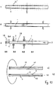
Mit der im Folgenden beschriebenen Maschine werden die Werkstücke 1 aus Holz, Kunststoff und dergleichen im Durchlaufverfahren konisch gehobelt. Hierbei werden die in Durchlaufrichtung 2 durch die Maschine rechten und linken Längsseiten 3, 4 des Werkstückes 1 so gehobelt, dass zumindest die eine Längsseite unter einem spitzen Winkel zur Durchlaufrichtung 2 liegt. Wie
Bei den Werkstücken 1 handelt es sich um brettartige Lamellen, aus denen beispielsweise Hauswände hergestellt werden. Hierfür werden die konischen Werkstücke 1 mit ihren Längsseiten 3, 4 aneinanderliegend fest verbunden, beispielsweise mittels einer entsprechenden Klebeschicht. Die konischen Werkstücke 1 werden hierbei jeweils um 180° gedreht aneinandergesetzt. Bei der Bildung beispielsweise einer Hauswand werden die aneinanderliegenden, miteinander verklebten Werkstücke 1 quer zu ihren Längsseiten 3, 4 verpresst.The
Die Maschine zur Herstellung der konischen Werkstücke 1 ist eine Durchlaufmaschine mit einem Abrichttisch 5, auf dem die Werkstücke 1 der Maschine zugeführt werden. Der Abrichttisch 5 befindet sich auf der Einlaufseite der Maschine. Zum Transport der Werkstücke 1 auf dem Abrichttisch 5 sind Vorschub/Transportwalzen 6 vorgesehen, die drehbar angetrieben werden und auf den Werkstücken 1 aufliegen.The machine for producing the
Der Abrichttisch 5 kann in Vertikalrichtung einstellbar sein, um das Maß der Spanabnahme an der Unterseite des Werkstückes 1 einzustellen. Das Werkstück 1 liegt an der in Einlaufrichtung rechten Seite des Abrichttisches 5 an einem in Durchlaufrichtung 2 sich erstreckenden Anschlaglineal 7 mit seiner in Durchlaufrichtung 2 rechten Längsseite 3 an.The dressing table 5 may be adjustable in the vertical direction to adjust the amount of chip removal on the underside of the
Bei dem in
Am Übergang vom Abrichttisch 5 zu einem Maschinentisch 8 befindet sich eine horizontale untere Abrichtspindel, auf der ein schematisch dargestelltes Abrichtwerkzeug 9 drehfest sitzt. Mit ihm wird beim Durchlauf des Werkstückes 1 dessen Unterseite spanabhebend bearbeitet, vorzugsweise gerade gehobelt. Der Werkstückabtrag wird durch die Höhe des Abrichttisches 5 relativ zum Abrichtwerkzeug 9 bestimmt.At the transition from the dressing table 5 to a machine table 8 is a horizontal lower dressing spindle, on which a schematically illustrated
In Durchlaufrichtung 2 hinter dem Abrichtwerkzeug 9 befindet sich eine vertikale rechte Spindel, auf der ein Werkzeug 10 drehfest sitzt. Mit ihm kann die in Transportrichtung rechte Längsseite 3 des Werkstückes 1 bearbeitet werden.In the direction of
Das Werkzeug 10 ist ein Hobelkopf mit geraden Messern, mit dem die Längsseite 3 des Werkstückes 1 während des Durchlaufes geradegehobelt wird. Die das Werkzeug 10 tragende Spindel ist quer zur Durchlaufrichtung 2 verstellbar. In
Während des Durchlaufes liegt das Werkstück 1 mit seiner einen Breitseite auf dem Maschinentisch 8 auf, der eine horizontale Auflage- und Bezugsebene für die Werkstücke 1 bildet.During the passage, the
Die Werkstücke 1 werden in Durchlaufrichtung 2 nach dem rechten Werkzeug 10 mit geringem Abstand zu einem Anschlag 14 durch die Maschine geführt. Er liegt parallel zur Durchlaufrichtung 2 und ist maschinenfest.The
Der Transport der Werkstücke 1 auf dem Maschinentisch 8 erfolgt ebenfalls mit den Vorschub/Transportwalzen 6, die in Durchlaufrichtung 2 mit Abstand hintereinander angeordnet und drehbar angetrieben sind. Die Vorschub/ Transportwalzen 6 liegen auf dem Werkstück 1 auf.The transport of the
In Durchlaufrichtung 2 hinter der linken vertikalen Spindel ist die Maschine mit einer oberen horizontalen Spindel versehen, auf der drehfest ein Werkzeug 15 sitzt. Mit ihm wird die Oberseite des Werkstückes 1 bei dessen Durchlauf durch die Maschine bearbeitet.In the direction of
Wie
In Durchlaufrichtung 2 mit Abstand hinter dem Werkzeug 16 hat die Maschine eine horizontale untere Tischwalze 17 zum besseren Transport der Werkstücke 1.In the direction of
Das zu bearbeitende Werkstück 1 wird auf dem Abrichttisch 5 der Maschine zugeführt. Im Bereich des Abrichttisches 5 befinden sich zwei Sensoren 18 und 19, zwischen denen das Werkstück 1 in Richtung auf die Maschine bzw. den Maschinentisch 8 transportiert wird. Wie aus
Die Krümmung tritt auf aufgrund der Lagerung und Trocknung, bei unbesäumten Werkstücken 1 aufgrund der natürlichen Wuchsform der Baumstämme und aufgrund freiwerdender Spannungen bei besäumten oder teilbesäumten Werkstücken.The curvature occurs due to storage and drying, with
Die noch unbearbeiteten Werkstücke 1 werden in der richtigen Lage durch eine vorgelagerte Mechanisierung dem Abrichttisch 5 zugeführt. Bei dieser vorgelagerten Mechanisierung werden die Werkstücke 1 gescannt und vorteilhaft so zugeführt, dass die Werkstücke mit der gekrümmten hohlen Längsseite 3 am Anschlaglineal 7 des Abrichttisches 5 anliegen.The still
Beim Durchlauf des Werkstückes 1 durch die beiden Sensoren 18, 19 werden die beiden Längsseiten 3, 4 des Werkstückes 1 vorteilhaft berührungsfrei abgetastet. Die Sensoren 18, 19 können beispielsweise Laserabstandssensoren sein, mit denen die Längsseiten 3, 4 abgetastet werden können.During the passage of the
Die Sensoren 18, 19 sind an eine (nicht dargestellte) Steuerung angeschlossen, der die Sensorsignale zugeführt werden. Mit diesen Sensorsignalen sorgt die Steuerung dann dafür, dass die in Durchlaufrichtung 2 nachfolgenden Werkzeuge 10, 12 radial so eingestellt werden, dass an den Längsseiten 3, 4 der notwendige Werkstückabtrag erfolgt.The
Die beiden Sensoren 18, 19 sind ortsfest angeordnet. Mit ihnen kann in einfacher Weise das Maß der Krümmung bzw. der Konizität des Werkzeuges 1 erfasst werden.The two
Der Sensor 18 bestimmt die Spanabnahme an der rechten Längsseite 3 des Werkstückes 1. Dementsprechend wird über die Steuerung das rechte Werkzeug 10 radial in Verstellrichtung 11 so eingestellt, dass die zunächst gekrümmte Längsseite 3 durch das Werkzeug 10 gerade gehobelt wird. Das Werkzeug 10 verfährt während des Hobelvorganges nicht, sondern behält seine durch die Steuerung eingestellte Lage während des Durchlaufes des Werkstückes 1 bei.The
Der Sensor 18 hat in Durchlaufrichtung 2 einen Abstand vom Werkzeug 10. der größer ist als die größte Länge des zu bearbeitenden Werkstückes 1. Dann kann das Werkzeug 10, bevor es mit dem vom Abrichttisch 5 zugeführten Werkstück 1 in Eingriff kommt, in seine notwendige Radiallage in Verstellrichtung 1 verstellt werden, da der Sensor 18 zuvor das Werkstück 1 über seine Länge erfasst und die entsprechenden Sensorsignale der Steuerung zugeführt hat.The
Der Sensor 19 liegt der Längsseite 4 des Werkstückes 1 mit Abstand gegenüber und erfasst den Verlauf dieser Längsseite während des Werkstückdurchlaufes. Mit Hilfe des Sensors 19 kann die Konizität des Werkstückes 1 und das Maß der Spanabnahme an der Längsseite 3 durch das Werkzeug 12 bestimmt werden.The
Mit dem Sensor 19 kann die Relativlage der Längsseite 4 des Werkstückes 1 in Bezug auf die Durchlaufrichtung 2 einfach erfasst werden. Wie in
Die beiden Werkzeuge 10, 12 werden vorteilhaft CNC-gesteuert in ihre jeweiligen Lagen in Verstellrichtung 11, 13 verstellt. Aufgrund der Schräglage der Längsseite 4 wird das Werkzeug 12 im Gegensatz zum Werkzeug 10 während des Durchlaufes des Werkstückes 1 in Verstellrichtung 13 entsprechend verstellt. Beim Ausführungsbeispiel nach
Das während des Durchlaufes des Werkstückes 1 maschinenfest angeordnete Werkzeug 12 ist, bevor es mit dem Werkstück 1 in Eingriff kommt, mittels der Signale des Sensors 18 durch die Steuerung so in Verstellrichtung 11 verstellt, dass an der Längsseite 3 bei minimaler Spanabnahme so viel Material vom Werkstück 1 abgetragen wird, dass es eine parallel zur Durchlaufrichtung 2 verlaufende und über seine Länge sich erstreckende vollständig sauber gehobelte gerade Längsseite 3 aufweist, wenn es durch das Werkzeug 10 bearbeitet worden ist.The
Dies ist in
Das Werkstück 1 wird, bevor es auf den Maschinentisch 8 gelangt, an seiner Unterseite 21 (
Der Maschinentisch 8, der auf einem Maschinenständer 23 angeordnet ist (
Mit den beiden Werkzeugen 15 und 16 werden die Oberseite sowie die Unterseite des Werkstückes 1 beim Durchlauf glatt gehobelt.With the two
Mit dem Werkzeug 16 kann die Unterseite 21 des Werkstückes 1 so abgehobelt werden, dass die Nut 22 entfernt ist. Sie ist nur so tief, dass mit Hilfe des Führungssteges 24 des Maschinentisches 8 das Werkstück 1 zuverlässig geführt werden kann. Darum muss mit dem Werkzeug 16 nur noch wenig Material an der Werkstückunterseite 21 abgetragen werden, um die Nut 22 zu entfernen. Der Materialverlust ist darum sehr gering.With the
Wie sich aus
Wenn die Werkstücke 1 quer zur Durchlaufrichtung 2 eine größere Breite haben, kann es vorteilhaft sein, In die Unterseite 21 des Werkstückes 1 beispielsweise zwei mit Abstand nebeneinanderliegende Nuten 22 einzufräsen, um eine sichere Führung der Werkstücke 1 auch bei größerer Breite sicherzustellen. Das Abrichtwerkzeug 9 ist dementsprechend so ausgebildet, dass mit ihm die Nuten gefräst werden können.If the
Da der Anschlag 14 nicht zur Führung des Werkstückes 1 durch die Maschine dient, können auch Werkstücke 1 einwandfrei konisch gehobelt werden, deren beide Längsseiten 3, 4 einen Winkel zur Durchlaufrichtung 2 aufweisen (
Auch bei solchen Werkstücken 1 mit schrägliegenden Längsseiten 3, 4 befindet sich an der Unterseite 21 wenigstens eine Nut 22, in die der Führungssteg 24 des Maschinentisches 8 eingreift. Wie bei der vorigen Ausführungsform ist die Nut 22 so vorgesehen, dass das Werkstück 1 nicht in Kontakt mit dem Anschlag 14 kommt.Even with
Die Werkstücke 1 werden kontinuierlich durch die Maschine transportiert. Hierbei kann der Abstand aufeinanderfolgender Werkstücke 1 gering gehalten werden, da die CNC-Steuerung die Werkzeuge 10, 12 in kurzer Zeit positionsgenau verstellen kann. Dadurch weist die Maschine einen hohen Durchsatz pro Zeiteinheit auf.The
Nachdem die Werkstücke 1 in der beschriebenen Weise konisch gehobelt worden sind, werden sie in einem nachfolgenden Verfahren zu größeren Elementen zusammengefügt. Beispielsweise können die Werkstücke 1 jeweils abwechselnd um 180° verdreht mit ihren Längsseiten 3, 4 aneinandergelegt und durch eine Klebeverbindung miteinander verbunden werden. In einer Presse werden die aneinanderliegenden Werkstücke so gegeneinander gepresst, dass sich stabile Platten ergeben. Sie können beispielsweise als Einzelplatten für die unterschiedlichsten Anwendungsfälle eingesetzt werden.After the
Es besteht die Möglichkeit, zwei oder mehr solcher Platten zu schichten und miteinander zu verkleben, um beispielsweise stabile Wandelemente aus wenigstens zwei Lagen zu fertigen. Für solche mehrlagigen Platten ist es nicht erforderlich, dass die Nut 22 an der Werkstückunterseite abgefräst wird. Die Platten können dann so aufeinandergelegt werden, dass sich die Nuten an den aneinanderliegenden Seitenflächen der Platten befinden. Die Nuten sind dann von außen nicht mehr zu sehen.It is possible to laminate two or more such plates and to glue together, for example, to produce stable wall elements from at least two layers. For such multi-layer plates, it is not necessary that the
Zur Herstellung solcher Wandelemente ist es auch möglich, die abwechselnd verdrehten Werkstücke 1 lose aneinander zu legen, um die erste Lage der Platte zu bilden. Auf sie wird eine weitere Lage aus den lose aneinander liegenden Werkstücken mit vorzugsweise rechtwinkliger Ausrichtung zu den Brettern der ersten Lage gelegt. Darauf kann eine weitere Plattenlage mit lose aneinandergelegten Werkstücken in gleicher Ausrichtung wie in der ersten Lage folgen. Die aufeinander liegenden Plattenlagen werden flächig miteinander verleimt und verpresst. Es werden so mehrschichtige Platten mit definierten Abmessungen gefertigt, abhängig von der Art der Presse.For the production of such wall elements, it is also possible to place the alternately
Mit den Werkzeugen 10, 12 können die Längsseiten 3, 4 mit hoher Oberflächengüte und hoher Geradheit hergestellt werden, so dass die konischen Werkstücke 1 anschließend in der zuvor geschilderten Weise zuverlässig zu Platten verleimt werden können.With the
Wenn die Werkstücke 1 mit der hohlen Seite 3 an das Anschlaglineal 7 angelegt werden, ist eine optimale Holzausnutzung möglich. Die Krümmung kann mit dem Sensor 18 in der beschriebenen Weise gemessen werden. Aus dieser Messung kann die Steuerung, der die Sensorsignale zugeführt werden, die notwendige, aber minimale Spanabnahme an der Längsseite 3 ermitteln. Die Werkstücke 1 werden unter Anlage am Anschlaglineal 7 dem Maschinentisch 8 zugeführt, wobei mit dem Abrichtwerkzeug 9 an der Werkstückunterseite 21 die Nut 22 gefräst wird. Das in Durchlaufrichtung 2 rechte Werkzeug 10 wird in der beschriebenen Weise durch die Steuerung quer zur Durchlaufrichtung 2 entsprechend der ermittelten Spanabnahme positioniert und bleibt dann während des Durchlaufes des Werkstückes 1 stehen. Dadurch ist eine sehr saubere Spanabnahme an der Längsseite 3 des Werkstückes 1 gewährleistet.When the
Mit dem Sensor 19, der sich an der in Durchlaufrichtung 2 linken Seite befindet, wird die Kontur der Längsseite 4 ermittelt und daraus der Verfahrweg des Werkzeuges 12 festgelegt. Dabei ist die Leitachse der Vorschubweg des Werkstückes 1 durch die Maschine. Der Vorschubweg wird durch die Vorschubgeschwindigkeit, mit der das Werkstück 1 durch die Maschine transportiert wird, sowie durch die Erfassung des Werkstückanfanges in der Maschine festgelegtWith the
Zur Erfassung des Werkstückanfanges ist ein Sensor 26 vorgesehen (
Es ist grundsätzlich möglich, hierfür auch die Sensoren 18, 19 heranzuziehen.In principle, it is also possible to use the
Zur Ermittlung des Transport/Vorschubweges können auch Messräder eingesetzt werden, die an der entsprechenden Werkstücklängsseite, vorteilhaft der Werkstückoberseite, anliegen. Vorteilhaft kann hierbei ebenfalls ein Sensor eingesetzt werden, mit dem der Anfang des Werkstückes erfasst wird.To determine the transport / feed path and measuring wheels can be used, which bear against the corresponding workpiece longitudinal side, advantageously the workpiece top. Advantageously, here also a sensor can be used, with which the beginning of the workpiece is detected.
Durch den den Werkstückanfang erfassenden Sensor 26 im Zusammenspiel mit der eingestellten Vorschubgeschwindigkeit und den Sensoren 18, 19 ist eine exakte und zuverlässige Verstellung der Werkzeuge 10, 12 gewährleistet.By detecting the
Je nach Konizität der rohen Werkstücke 1 können diese durch Anpassen der Verstellgeschwindigkeit der Werkzeuge 10 bzw. 12 in Abhängigkeit vom Vorschubweg bzw. der Vorschubgeschwindigkeit des Werkstückes 1 so bearbeitet werden, dass die jeweiligen Längsseiten 3, 4 unterschiedlich stark in Bezug auf die Durchlaufrichtung 2 geneigt sind. Auf diese Weise lassen sich definierte Konizitätsklassen erreichen. Dadurch ist beim späteren Zusammenfügen sichergestellt, dass aus den konischen Werkstücken 1 Tafeln bzw. Bretterlagen zusammengefügt werden können, die in etwa Rechteckform haben.Depending on the conicity of the
Beim beschriebenen und dargestellten Ausführungsbeispiel werden die Werkstücke 1 jeweils mit ihrem schmaleren Ende, dem sogenannten Zopf, nach vorn durch die Maschine transportiert. Grundsätzlich können die Werkstücke 1 aber auch so angeordnet werden, dass sie mit ihrem breiteren Ende nach vorn durch die Maschine transportiert werden.In the described and illustrated embodiment, the
Schließlich ist es auch möglich, die Bearbeitung der Werkstücke 1 während ihres Durchlaufes durch die Maschine so vorzunehmen, dass das linke Werkzeug 12 feststeht und das rechte Werkzeug 10 während des Durchlaufes des Werkstückes 1 verstellt wird, wie dies anhand des linken Werkzeuges 12 beschrieben worden ist.Finally, it is also possible to perform the machining of the
Mit der beschriebenen Maschine und dem Verfahren lassen sich konische Bretter in verleimfähiger Qualität und bei einer hohen Rohholzausbeute herstellen. Die hohe Rohholzausbeute, also die maximale Deckbreite, resultiert zum einen aus der Vermessung der Schmalseiten der Werkstücke und der daraus abgeleiteten Bearbeitung mit minimaler Spanabnahme, und zum anderen durch die Nutzung konischer Ausgangsbretter, die entsprechend der natürlichen Wuchsform der Bäume in einem vorgelagerten Prozess hergestellt wurden.With the described machine and the method, conical boards can be produced in a glueable quality and at a high raw wood yield. The high raw wood yield, ie the maximum deck width, results from the measurement of the narrow sides of the workpieces and the processing derived from them with minimal chip removal, and also from the use of conical starting boards, which were produced in an upstream process according to the natural growth habit of the trees ,
Im restlichen Teil des Werkstückes 1 wurden die so genannten Waldkanten 27, 28 durch den Besäumprozess noch nicht bearbeitet und das Werkstück läuft bis zu seinem schmaleren Ende hin zu. Auch im besäumten Bereich kann, über die Werkstückdicke betrachtet, noch ein Teil Waldkante vorhanden sein.In the remaining part of the
Mit gestrichelten Linien ist das Werkstück 1 nach der Bearbeitung dargestellt. In diesem Falle hat das Werkstück 1 nach der Bearbeitung über seine Länge durchgehend gerade Längsseiten 3, 4, die in Richtung auf das schmalere Ende des Werkstückes 1 konvergierend verlaufen.With dashed lines, the
Das Werkstück 1 kann hierbei so bearbeitet werden, dass es in Bezug auf eine Symmetrielinie 29 spiegelsymmetrisch ausgebildet ist. Dann besteht beispielhaft die Möglichkeit, das Werkstück 1 nach seiner Bearbeitung längs der Symmetrielinie 29 in zwei Werkstücke aufzusägen (
In
Im Bereich, in dem das Werkstück über seine Stärke bzw. die Waldkanten 27, 28 nicht vollständig oder gar nicht besäumt wurden, hat das unbearbeitete Werkstück 1 die Querschnittsformen II bzw. III. Die Waldkanten 27, 28 verlaufen von der Unterseite 30 des Werkstückes 1 aus in Richtung auf dessen Oberseite 31 konvergierend.In the area in which the workpiece was not completely or not at all trimmed over its thickness or the forest edges 27, 28, the
Wenn das Werkstück 1 fertig bearbeitet ist, hat es über seine Länge durchgehend rechteckigen Querschnitt, wobei die Breite des Werkstückes 1 kontinuierlich in Richtung auf das schmalere Ende abnimmt.When the
Werden die Werkstücke 1 für Innenlagen von Platten eingesetzt, sind kleine, in der Größe definierbare Waldkantenreste zu akzeptieren.If the
Da die Waldkanten 27, 28 geneigt verlaufen, wird das unbearbeitete Werkstück bei seinem Transport in Richtung auf die Werkzeuge der Maschine von der Oberseite aus erfasst, vorzugsweise mittels Scannern. Sie sind so angeordnet, dass sie den unteren Rand 32 und den oberen Rand 33 der Waldkanten 27, 28 erfassen. Die Werkzeuge 10, 12 können dann so eingestellt werden, dass die gewünschte Kontur des Werkstückes 1 bei minimalem Spanabtrag hergestellt werden kann.Since the forest edges 27, 28 are inclined, the unprocessed workpiece is detected from the top during its transport in the direction of the tools of the machine, preferably by means of scanners. They are arranged so that they cover the
Wie anhand der vorigen Ausführungsform beschrieben, kann das Werkstück 1 zusätzlich hinsichtlich seiner Länge sowie des Anfangs und des Endes des Werkstückes 1 durch die Sensoren 18, 19, 26 (
Die gewünschte Konizität (gestrichelte Linien) des Werkstückes 1 kann so eingestellt werden, dass das fertig bearbeitete Werkstück einer bestimmten Konizitätsklasse zugeordnet werden kann.The desired conicity (dashed lines) of the
Als Erfassungseinrichtungen, die das Werkstück 1 von oben erfassen, können auch bildgebende Systeme, wie Kameras, oder auch Querdurchlaufscanner, Längsdurchlaufscanner und dgl., eingesetzt werden. Die Werkstücke 1 sind bei der Zuführung auf dem Abrichttisch 5 bzw. dem Maschinentisch 8 so angeordnet, dass die Waldkanten 27, 28 von der Auflageseite 30 aus nach oben und schräg nach innen verlaufen. Dann können die Erfassungseinrichtungen, die im Bereich oberhalb des Werkstückes 1 angeordnet sind, die beiden Ränder 32, 33 der Waldkanten 27, 28 erfassen.As detection means which grasp the
Die Erfassungseinrichtung ist vorteilhaft im Zuführbereich der Werkstücke 1 zur Maschine angeordnet.The detection device is advantageously arranged in the feed region of the
Wie bei den vorigen Ausführungsformen kann die jeweilige Werkstückidentifizierung in der Maschine über die exakte Teileverfolgung oder mittels einer Kennzeichnung, beispielsweise mittels Barcode, Transponder und dergleichen, gewährleistet werden.As in the previous embodiments, the respective workpiece identification in the machine can be ensured via the exact part tracking or by means of a marking, for example by means of a barcode, transponder and the like.
Die Werkstücke 1 können abweichend von der Ausbildung gemäß
Die Vorschub/Transportwalzen 6 sind vorteilhaft quer zur Durchlaufrichtung 2 des Werkstückes 1 verstellbar, so dass die Vorschub/Transportwalzen 6 in Abhängigkeit von der Breite des Werkstückes 1 optimal eingestellt werden können.The feed /
Anhand von
Bei der Zuführung wird das Werkstück 1 mittels eines Querdurchlaufscanners 26" von oben gescannt (gepunktete Linien in Schritt 1 der
Je nach Zuführrichtung kann der Scanvorgang durch einen Querdurchlaufscanner 26" oder Längsdurchlaufscanner realisiert werden.Depending on the feed direction, the scanning process can be realized by a
Sobald das Werkstück 1 auf den Abrichttisch 5 gelangt (
Vorteilhaft werden besäumte Werkstücke an das Fügelineal 7, wie anhand
Auf dem Abrichttisch 5 wird die Lage des zu bearbeitenden Werkstückes 1 mittels eines weiteren Scanners 26' (
Die am Werkstück 1 vorzunehmende Bearbeitung ist im Schritt 2 der
An der Unterseite 21 des Werkstückes 1 wird die Nut 22 mit dem Abrichtwerkzeug 9 (
Anschließend wird das Werkstück 1 rechts und links vorgespant/vorgehobelt (3.2 in Schritt 3 der
Anschließend wird das Werkstück 1 an seinen in Durchlaufrichtung 2 verlaufenden Längsseiten mit den entsprechenden Werkzeugen 10', 12' fertig gehobelt (3.3 bei Schritt 3 der
Schließlich wird bei 3.4 das Werkstück an der Ober- und an der Unterseite mit den entsprechenden Werkzeugen 15, 16 (
Die Werkzeuge 10, 12; 10', 12' werden während des Vorschubes des Werkstückes 1 quer zur Durchlaufrichtung 2 entsprechend dem gewünschten Konizitätswinkel stetig verstellt, wie bei der ersten Ausführungsform im Einzelnen erläutert worden ist.The
Die gemäß den Schritten 1 bis 3 der
Bei der Verfahrensweise gemäß
In
Auf diese Weise werden Bretterpaare gebildet, wobei die entsprechenden Werkstücke vorteilhaft dem Zwischenpuffer entnommen werden.In this way, pairs of boards are formed, the corresponding workpieces are advantageously removed from the intermediate buffer.
Bei einer anderen Verfahrensweise (
Bei der Verfahrensweise gemäß
Die aus zwei aneinander liegenden Werkstücken gebildeten Bretterpaare 37 gemäß den
Anhand von
Im Schritt 3 werden die Operationen 3.1 bis 3.3 in gleicher Weise am Werkstück 1 vorgenommen wie beim Ausführungsbeispiel gemäß
An der Position 3.4 im Schritt 3 erfolgt das Längsaufsägen des Werkstückes 1 bei seinem Transport in Durchlaufrichtung 2. Die entsprechende (nicht dargestellte) Trennsäge befindet sich vorteilhaft im Bereich unterhalb des Werkstückes 1, kann aber auch im Bereich oberhalb des Werkstückes 1 so angeordnet sein, dass sie das Werkstück 1 in Längsrichtung auftrennt. Der durch die Trennsäge erzeugte Trennschnitt 38 liegt in einer zur Symmetrieachse 29 des Werkstückes 1 parallelen Achse. Vorzugsweise liegt der Trennschnitt 38 in der Symmetrieachse 29, wodurch das Werkstück in halber Breite aufgetrennt wird.At position 3.4 in
Schließlich wird bei 3.5 das Werkstück 1 an der Ober- und Unterseite gehobelt und somit auf die gewünschte Brettstärke gebracht.Finally, at 3.5, the
Aus den beiden Werkstückteilen 1.1, 1.2 werden jeweils Bretterpaare 37 gebildet, die wieder parallele äußere Längsseiten haben. Hierbei wird beispielhaft das Werkstückteil 1.2 um eine quer zu seiner Längsrichtung liegende Achse gedreht.From the two workpiece parts 1.1, 1.2 respectively pairs of
Aus den so gebildeten Bretterpaaren 37 wird wieder, wie anhand
Da die Werkstücke 1 im Schritt 3.5 in ihrer Länge aufgeteilt werden, können die so entstehenden Werkstückteile 1.1, 1.2 unmittelbar weiterverarbeitet werden. Es ist kein Puffer für die Werkstückteile erforderlich.Since the
Eine weitere Möglichkeit besteht darin, die Werkstücke 1 nicht nur unter Berücksichtigung der Konizitäsklasse, sondern auch unter Berücksichtigung von Astpositionen in den Werkstücken (Werkstückanfang, Werkstückmitte, Werkstückende) in verschiedenen Puffern abzulegen. Die Werkstücke 1 können dann den Puffern so entnommen und zu dem Bretterteppich zusammengelegt werden, dass bei dem späteren Verfahrensschritt des Auskappens (Entfernens) von Ästen wenig Abfall entsteht.Another possibility is the
Wie sich aus den beschriebenen Ausführungsbeispielen ergibt, können außer den über ihre gesamte Länge konischen besäumten Werkstücken 1 auch zumindest über eine Teillänge parallel besäumte oder nicht besäumte Werkstücke der beschriebenen Hobelbearbeitung zugeführt werden (
Die Vermessung des Werkstückes von der Seite mittels der Sensoren 18, 19, wie anhand von
Bei dem Verfahren nach
Beim Durchlauf des Werkstückes 1 durch die Kehlmaschine erfolgt die konische Bearbeitung, indem das entsprechende Werkzeug quer zur Durchlaufrichtung 2 verstellt wird. Die so hergestellten konischen Werkstücke 1 werden entsprechend der Konizitätsklasse in Puffern zwischengespeichert. Aus diesem Puffer werden dann die Werkstücke beim Verfahren nach
Bei der Verfahrensweise nach
Beim Verfahren gemäß
Während bei der Maschine gemäß den
Bei den beschriebenen Ausführungsbeispielen werden die Seitenränder mit den vertikalen Werkzeugen 10, 10', 12, 12' so bearbeitet, dass die Seiten der Werkstücke rechtwinklig zur Ober- und Unterseite der Werkstücke liegen. Es ist darüber hinaus möglich, die Längsseiten 3, 4 der Werkstücke 1 mit schräggestellten Werkzeugen bzw. mit Profilwerkzeugen zu bearbeiten. Dadurch sind die Längsseiten 3, 4 zur Ober- und Unterseite schräg verlaufend ausgebildet. Die Werkstücke haben daher einen trapezförmigen Querschnitt. Dadurch kann die Holzausbeute deutlich gesteigert werden.In the described embodiments, the side edges with the
Bei der Bearbeitung mit schräggestellten Werkzeugen 10, 10; 12, 12' sind die Spindeln, auf denen die Werkzeuge 10, 10; 12, 12' sitzen, so ausgebildet, dass sie sich um eine parallel zur Durchlaufrichtung 2 verlaufende Achse schwenken lassen. Der Schwenkwinkel wird entsprechend der Form und Lage der Waldkante ebenso wie die Konizität aus den Daten der gescannten Werkstücke 1 ermittelt. Über die Maschinensteuerung werden die Werkzeuge 10, 10; 12, 12' vorzugsweise über CNC-gesteuerte Antriebsachsen in die entsprechende Lage verschwenkt.When editing with slanted
Zur Bildung der Bretterpaare 37 wird das eine Werkstückteil 1.2 (
Claims (17)
dadurch gekennzeichnet, dass zum Transport der Werkstücke (1) durch die Maschine wenigstens eine in Transportrichtung (2) wirksame Nut-Steg-Führung (22, 24) vorgesehen ist.Machine for conical machining, in particular conical planing, of workpieces (1) made of wood, plastic and the like, which can be transported by the machine, with at least one support (8) for the workpieces (1) and with at least two rotatably driven tools (10 , 12), with which in the transport direction of the workpieces (1) right and / or left longitudinal side of the workpieces (1) to be processed and of which at least one tool (10, 12) transversely to the transport direction (2) is adjustable,
characterized in that for transporting the workpieces (1) through the machine at least one in the transport direction (2) effective groove-web guide (22, 24) is provided.
dadurch gekennzeichnet, dass die Nut-Steg-Führung (22, 24) wenigstens einen in Transportrichtung (2) verlaufenden Steg (24) aufweist, der an der Maschine, vorteilhaft an der vorzugsweise als Maschinentisch ausgebildeten Auflage (8) vorgesehen ist und in eine in Transportrichtung (2) verlaufende Nut (22) des Werkstückes (1) eingreift.Machine according to claim 1,
characterized in that the groove-web guide (22, 24) has at least one in the transport direction (2) extending web (24) which is provided on the machine, advantageously on the preferably designed as a machine table support (8) and in a in the transport direction (2) extending groove (22) of the workpiece (1) engages.
dadurch gekennzeichnet, dass der Steg (24) zumindest bis in Höhe der Werkzeuge (10, 10', 12, 12') erstreckt.Machine according to claim 1 or 2,
characterized in that the web (24) extends at least up to the level of the tools (10, 10 ', 12, 12').
dadurch gekennzeichnet, dass die Maschine wenigstens ein weiteres Werkzeug (9) aufweist, mit dem die Nut (22) im Werkstück (1) herstellbar ist und das vorzugsweise ein horizontales Abrichtwerkzeug ist, mit dem die Nut (22) in der Unterseite (21) des Werkstückes (1) herstellbar ist.Machine according to one of claims 1 to 3,
characterized in that the machine at least one further Tool (9), with which the groove (22) in the workpiece (1) can be produced and which is preferably a horizontal dressing tool with which the groove (22) in the bottom (21) of the workpiece (1) can be produced.
dadurch gekennzeichnet, dass die Werkzeuge (10, 10', 12, 12') an eine CNC-Steuerung angeschlossen sind, an die vorzugsweise Messelemente (18, 19, 26', 26") angeschlossen sind, die zumindest die eine in Transportrichtung verlaufende Werkstückseite (3, 4) erfassen.Machine according to one of claims 1 to 4,
characterized in that the tools (10, 10 ', 12, 12') are connected to a CNC control, to which preferably measuring elements (18, 19, 26 ', 26 ") are connected, at least one extending in the transport direction Grasp workpiece side (3, 4).
dadurch gekennzeichnet, dass die CNC-Steuerung die von den Messelementen (18, 19, 26', 26") erhaltenen Signale auswertet und entsprechend der Auswertung die Werkzeuge (10, 10', 12, 12') quer zur Transportrichtung (2) steuert.Machine according to one of claims 1 to 5,
characterized in that the CNC control evaluates the signals received from the measuring elements (18, 19, 26 ', 26 ") and, according to the evaluation, controls the tools (10, 10', 12, 12 ') transversely to the transport direction (2) ,
dadurch gekennzeichnet, dass zur Erfassung des Werkstückanfanges wenigstens ein Sensor (26) vorgesehen ist, der vorzugsweise an die CNC-Steuerung angeschlossen ist.Machine according to one of claims 1 to 6,
characterized in that for detecting the workpiece beginning at least one sensor (26) is provided, which is preferably connected to the CNC control.
dadurch gekennzeichnet, dass der Auflage (8) wenigstens ein Abrichttisch (3) vorgeschaltet ist, der mit wenigstens einem in Transportrichtung (2) sich erstreckenden Anschlag (7) versehen ist.Machine according to one of claims 1 to 7,
characterized in that the support (8) at least one dressing table (3) is connected upstream, which is provided with at least one in the transport direction (2) extending stop (7).
dadurch gekennzeichnet, dass das Werkstück (1) mit einer hohlen Werkstückseite (3) am Anschlag (7) des Abrichttisches (3) anliegt.Machine according to one of claims 1 to 8,
characterized in that the workpiece (1) rests with a hollow workpiece side (3) on the stop (7) of the dressing table (3).
dadurch gekennzeichnet, dass die Messelemente (18, 19, 26') im Bereich des Abrichttisches (3) angeordnet sind, und dass vorteilhaft der in Transportrichtung (2) gemessene Abstand zwischen den Messelementen (18, 19, 26') und dem ersten der beiden Werkzeuge (10, 10', 12, 12') größer ist als die Länge des Werkstückes (1).Machine according to one of claims 1 to 9,
characterized in that the measuring elements (18, 19, 26 ') in the area the dressing table (3) are arranged, and that advantageously the distance between the measuring elements (18, 19, 26 ') and the first of the two tools (10, 10', 12, 12 ') measured in the transporting direction (2) is greater than the length of the workpiece (1).
dadurch gekennzeichnet, dass die Werkstücke (1) vor oder während ihrer Zuführung hinsichtlich zumindest der zu bearbeitenden Konizität vermessen werden, dass am Werkstück (1) zumindest ein Formschlusselement (22) angebracht wird, das mit wenigstens einem Gegenformschlusselement (24) beim Transport des Werkstückes durch die Maschine so zusammenwirkt, dass das Werkstück (1) in Transportrichtung (2) geführt wird, und dass das Werkzeug (10, 10', 12, 12') während des Werkstückdurchlaufes in Abhängigkeit von der ermittelten Konizität des Werkstückes (1) quer zur Transportrichtung (2) verstellt wird.Method for conical machining, in particular conical planing, of workpieces made of wood, plastic and the like, in particular using a machine according to one of claims 1 to 10, in which the workpieces (1) on their in the transport direction (2) right and / or left Long side with at least one tool (10, 10 ', 12, 12') are processed,
characterized in that the workpieces (1) are measured prior to or during their supply with respect to at least the conicity to be machined, that at least one positive locking element (22) is attached to the workpiece (1), with at least one counter-form-locking element (24) during transport of the workpiece cooperates through the machine so that the workpiece (1) in the transport direction (2) is guided, and that the tool (10, 10 ', 12, 12') during the workpiece passage in dependence on the determined conicity of the workpiece (1) transversely is adjusted to the transport direction (2).
dadurch gekennzeichnet, dass die Position des Werkstückes (1) in Bezug auf das Werkzeug (10, 10', 12, 12') erfasst wird.Method according to claim 11,
characterized in that the position of the workpiece (1) with respect to the tool (10, 10 ', 12, 12') is detected.
dadurch gekennzeichnet, dass die Breite und/oder die Konizität des Werkstückes (1) durch Messelemente (18, 19, 26', 26") erfasst und deren Signale einer Steuerung für die Werkzeuge ('10, 10', 12, 12') zugeführt werden.Method according to claim 11 or 12,
characterized in that the width and / or the taper of the workpiece (1) by measuring elements (18, 19, 26 ', 26 ") detected and their signals a controller for the tools ('10, 10', 12, 12 ') be supplied.
dadurch gekennzeichnet, dass die Werkstücke (1) paarweise zu Bretterpaaren (37) mit etwa parallelen Längsseiten und etwa rechteckigem Umriss gelegt werden, und dass die Bretterpaare (37) vorzugsweise zu Bretterteppichen aneinandergesetzt werden.Method according to one of claims 11 to 13,
characterized in that the workpieces (1) in pairs to pairs of boards (37) are laid with approximately parallel longitudinal sides and approximately rectangular outline, and that the pairs of boards (37) are preferably placed against each other to board carpets.
dadurch gekennzeichnet, dass die Werkstücke (1) nach der konischen Bearbeitung in zwei Werkstückteile (1.1, 1.2) aufgeteilt werden, und dass das eine Werkstückteil (1.1, 1.2) gedreht und mit dem anderen Werkstückteil das Bretterpaar (37) bildet.Method according to one of claims 11 to 14,
characterized in that the workpieces (1) after the conical machining into two workpiece parts (1.1, 1.2) are divided, and that one workpiece part (1.1, 1.2) is rotated and forms with the other workpiece part, the board pair (37).
dadurch gekennzeichnet, dass die Werkstücke (1) nach der konischen Bearbeitung in halber Länge zur Bildung der beiden Werkstückteile (1.1, 1.2) aufgetrennt werden.Method according to one of claims 11 to 15,
characterized in that the workpieces (1) after the conical machining in half length to form the two workpiece parts (1.1, 1.2) are separated.
dadurch gekennzeichnet, dass die Werkstücke (1) nach der konischen Bearbeitung in einer zur Symmetrieachse (29) des Werkstückes (1) parallelen Achse zur Bildung der beiden Werkstückteile (1.1, 1.2) aufgetrennt werden.Method according to one of claims 11 to 16,
characterized in that the workpieces (1) after the conical machining in an axis of symmetry (29) of the workpiece (1) parallel axis for forming the two workpiece parts (1.1, 1.2) are separated.
Applications Claiming Priority (2)
| Application Number | Priority Date | Filing Date | Title |
|---|---|---|---|
| DE102018002704 | 2018-03-29 | ||
| DE102019001921.0A DE102019001921A1 (en) | 2018-03-29 | 2019-03-16 | Machine and method for conical machining, in particular for conical planing, of workpieces made of wood, plastic and the like |
Publications (1)
| Publication Number | Publication Date |
|---|---|
| EP3546163A1 true EP3546163A1 (en) | 2019-10-02 |
Family
ID=67910227
Family Applications (1)
| Application Number | Title | Priority Date | Filing Date |
|---|---|---|---|
| EP19000148.7A Pending EP3546163A1 (en) | 2018-03-29 | 2019-03-26 | Machine and method for conical machining, in particular for conical planing of a workpiece made of wood, plastic and similar |
Country Status (3)
| Country | Link |
|---|---|
| US (1) | US11345058B2 (en) |
| EP (1) | EP3546163A1 (en) |
| DE (1) | DE102019001921A1 (en) |
Cited By (2)
| Publication number | Priority date | Publication date | Assignee | Title |
|---|---|---|---|---|
| CN111452144A (en) * | 2020-06-04 | 2020-07-28 | 戚利明 | Wood processing device |
| WO2023213873A1 (en) * | 2022-05-05 | 2023-11-09 | Homag Gmbh | Machining device and method |
Families Citing this family (2)
| Publication number | Priority date | Publication date | Assignee | Title |
|---|---|---|---|---|
| BE1027083B1 (en) * | 2019-02-26 | 2020-09-24 | Flooring Ind Ltd Sarl | Sliding or pressure shoe for a continuous milling machine and method for manufacturing panels |
| CN114633319A (en) * | 2022-03-14 | 2022-06-17 | 广西华辉装饰集团有限公司 | Multifunctional slotting all-in-one machine |
Citations (3)
| Publication number | Priority date | Publication date | Assignee | Title |
|---|---|---|---|---|
| DE102004054973A1 (en) * | 2004-11-13 | 2006-07-13 | Homag Holzbearbeitungssysteme Ag | Double end tenoner with workpiece guide rail and method for the production of workpieces hereby |
| BE1016561A6 (en) * | 2005-03-31 | 2007-01-09 | Flooring Ind Ltd | Floor panel manufacturing method, involves providing panels at lower side with guiding groove and providing two opposite sides with profiled edge regions that comprise coupling parts |
| WO2015086332A1 (en) * | 2013-12-10 | 2015-06-18 | Hans-Peter Leitinger | Sawn timber panel made of side boards, and method for the production thereof |
Family Cites Families (13)
| Publication number | Priority date | Publication date | Assignee | Title |
|---|---|---|---|---|
| US769980A (en) | 1904-01-12 | 1904-09-13 | Charles W Borg | Tongue-shaping machine. |
| FR1394002A (en) | 1963-08-02 | 1965-04-02 | Constant Philips | Planing device for planing wood for multi-sided planing machines |
| SE314495B (en) | 1967-10-10 | 1969-09-08 | Stenbergs Maskinbyra Ab | |
| US3934630A (en) * | 1973-04-16 | 1976-01-27 | Cockle Roy R | Method and apparatus for producing rough cut lumber |
| US4230163A (en) * | 1978-02-27 | 1980-10-28 | Vermont Log Building, Inc. | Log-planing machine |
| CA2111893C (en) * | 1993-12-20 | 1996-08-06 | Rene Achard | Chipping canter |
| DE19616165A1 (en) | 1996-04-24 | 1997-10-30 | Hoffmann & Kuehnhenrich Gmbh | Metal working planing or profiling machine with multiple adjustable cutting tools |
| DE19756503B4 (en) | 1997-12-19 | 2007-09-27 | Michael Weinig Ag | moulder |
| US6062281A (en) * | 1999-05-13 | 2000-05-16 | U.S. Natural Resources | Vertical arbor saw for shape sawing a log |
| DE10328204A1 (en) | 2003-06-24 | 2005-02-03 | Homag Holzbearbeitungssysteme Ag | Machine for profiling elongate, plate-shaped workpieces along the longitudinal edges |
| US20110079324A1 (en) * | 2007-03-20 | 2011-04-07 | McDonough Manufacturing | Board edger with tandem saw boxes |
| CA2770635C (en) * | 2011-03-07 | 2019-02-19 | Earl Barker | Machine vision based sawmill audit system |
| CA2878611A1 (en) | 2014-01-15 | 2015-07-15 | Russell R. Kennedy | Servofetcher positioning device and method for edger systems |
-
2019
- 2019-03-16 DE DE102019001921.0A patent/DE102019001921A1/en active Pending
- 2019-03-26 EP EP19000148.7A patent/EP3546163A1/en active Pending
- 2019-03-29 US US16/368,904 patent/US11345058B2/en active Active
Patent Citations (3)
| Publication number | Priority date | Publication date | Assignee | Title |
|---|---|---|---|---|
| DE102004054973A1 (en) * | 2004-11-13 | 2006-07-13 | Homag Holzbearbeitungssysteme Ag | Double end tenoner with workpiece guide rail and method for the production of workpieces hereby |
| BE1016561A6 (en) * | 2005-03-31 | 2007-01-09 | Flooring Ind Ltd | Floor panel manufacturing method, involves providing panels at lower side with guiding groove and providing two opposite sides with profiled edge regions that comprise coupling parts |
| WO2015086332A1 (en) * | 2013-12-10 | 2015-06-18 | Hans-Peter Leitinger | Sawn timber panel made of side boards, and method for the production thereof |
Cited By (2)
| Publication number | Priority date | Publication date | Assignee | Title |
|---|---|---|---|---|
| CN111452144A (en) * | 2020-06-04 | 2020-07-28 | 戚利明 | Wood processing device |
| WO2023213873A1 (en) * | 2022-05-05 | 2023-11-09 | Homag Gmbh | Machining device and method |
Also Published As
| Publication number | Publication date |
|---|---|
| US20190299483A1 (en) | 2019-10-03 |
| DE102019001921A1 (en) | 2019-10-02 |
| US11345058B2 (en) | 2022-05-31 |
Similar Documents
| Publication | Publication Date | Title |
|---|---|---|
| EP3546163A1 (en) | Machine and method for conical machining, in particular for conical planing of a workpiece made of wood, plastic and similar | |
| EP3294510B1 (en) | Method for producing panels having recesses | |
| DE3343953A1 (en) | METHOD FOR PROCESSING CURVED STEM | |
| EP2308659B1 (en) | Device and method for aligning workpieces | |
| EP3453503B1 (en) | Machine for machining elongated work pieces consisting of wood, synthetic material or the like and method for measuring such elongated workpieces | |
| DD289967B5 (en) | Method and device for producing wooden lamellae from sawn timber | |
| EP3498423B1 (en) | Processing device for processing the narrow side of a workpiece and method | |
| DE19756280A1 (en) | Moulder | |
| EP2221134B1 (en) | Processing device | |
| DE2947993C3 (en) | Process for longitudinally cutting pieces of wood | |
| DE4212432A1 (en) | Device for the non-cutting cutting of wooden lamella from a square timber | |
| DE2920755A1 (en) | DEVICE AND METHOD FOR THE FRONT SIDE COMPOSITION OF WOODS BY MEANS OF FINGER JOINTS | |
| WO2017067889A1 (en) | Method for beveling veneers | |
| EP2665587B1 (en) | Moulder for machining rod-shaped workpieces consisting of wood, plastic and similar | |
| DE102017011825B4 (en) | Method for cutting elongated workpieces made of wood, plastic and the like into lamellas and processing machine for carrying out such a method | |
| EP3659765A1 (en) | Device for machining elongated workpieces made of wood, plastic and the like | |
| DE3514892C1 (en) | Method and device for cutting timber, in particular for dividing by chip removal tree trunks provided with construction edges | |
| DE19547193A1 (en) | Method and device for cutting a tree trunk | |
| EP1365899A2 (en) | Method and device for reducing round timber that is bent in one plane to wood products | |
| DE3607146A1 (en) | METHOD AND MACHINE FOR THE PROCESSING OF BARRELS | |
| DE102004051933A1 (en) | Device and method for profiling tree trunks | |
| DE102014016629A1 (en) | Plant for the production and / or treatment of glazing beads and methods using such a plant | |
| DE4138734C2 (en) | Method and device for processing both longitudinal sides of sawn timber conveyed in the longitudinal direction | |
| DE19509653C1 (en) | Parquet strip mfg. process | |
| DE102019002689A1 (en) | Method for producing a longitudinal groove with an undercut in a workpiece made of wood, plastic and the like, as well as a machine for carrying out such a method |
Legal Events
| Date | Code | Title | Description |
|---|---|---|---|
| PUAI | Public reference made under article 153(3) epc to a published international application that has entered the european phase |
Free format text: ORIGINAL CODE: 0009012 |
|
| STAA | Information on the status of an ep patent application or granted ep patent |
Free format text: STATUS: THE APPLICATION HAS BEEN PUBLISHED |
|
| AK | Designated contracting states |
Kind code of ref document: A1 Designated state(s): AL AT BE BG CH CY CZ DE DK EE ES FI FR GB GR HR HU IE IS IT LI LT LU LV MC MK MT NL NO PL PT RO RS SE SI SK SM TR |
|
| AX | Request for extension of the european patent |
Extension state: BA ME |
|
| STAA | Information on the status of an ep patent application or granted ep patent |
Free format text: STATUS: REQUEST FOR EXAMINATION WAS MADE |
|
| 17P | Request for examination filed |
Effective date: 20200402 |
|
| RBV | Designated contracting states (corrected) |
Designated state(s): AL AT BE BG CH CY CZ DE DK EE ES FI FR GB GR HR HU IE IS IT LI LT LU LV MC MK MT NL NO PL PT RO RS SE SI SK SM TR |
|
| STAA | Information on the status of an ep patent application or granted ep patent |
Free format text: STATUS: EXAMINATION IS IN PROGRESS |
|
| 17Q | First examination report despatched |
Effective date: 20210804 |