EP3545187B1 - Verbrennungsionisierungssensor für zündkerze - Google Patents
Verbrennungsionisierungssensor für zündkerze Download PDFInfo
- Publication number
- EP3545187B1 EP3545187B1 EP17873286.3A EP17873286A EP3545187B1 EP 3545187 B1 EP3545187 B1 EP 3545187B1 EP 17873286 A EP17873286 A EP 17873286A EP 3545187 B1 EP3545187 B1 EP 3545187B1
- Authority
- EP
- European Patent Office
- Prior art keywords
- spark plug
- electrode
- sensing electrode
- electrically
- sparking
- Prior art date
- Legal status (The legal status is an assumption and is not a legal conclusion. Google has not performed a legal analysis and makes no representation as to the accuracy of the status listed.)
- Active
Links
Images






Classifications
-
- H—ELECTRICITY
- H01—ELECTRIC ELEMENTS
- H01T—SPARK GAPS; OVERVOLTAGE ARRESTERS USING SPARK GAPS; SPARKING PLUGS; CORONA DEVICES; GENERATING IONS TO BE INTRODUCED INTO NON-ENCLOSED GASES
- H01T13/00—Sparking plugs
- H01T13/20—Sparking plugs characterised by features of the electrodes or insulation
- H01T13/22—Sparking plugs characterised by features of the electrodes or insulation having two or more electrodes embedded in insulation
-
- F—MECHANICAL ENGINEERING; LIGHTING; HEATING; WEAPONS; BLASTING
- F02—COMBUSTION ENGINES; HOT-GAS OR COMBUSTION-PRODUCT ENGINE PLANTS
- F02P—IGNITION, OTHER THAN COMPRESSION IGNITION, FOR INTERNAL-COMBUSTION ENGINES; TESTING OF IGNITION TIMING IN COMPRESSION-IGNITION ENGINES
- F02P13/00—Sparking plugs structurally combined with other parts of internal-combustion engines
-
- G—PHYSICS
- G01—MEASURING; TESTING
- G01N—INVESTIGATING OR ANALYSING MATERIALS BY DETERMINING THEIR CHEMICAL OR PHYSICAL PROPERTIES
- G01N27/00—Investigating or analysing materials by the use of electric, electrochemical, or magnetic means
- G01N27/62—Investigating or analysing materials by the use of electric, electrochemical, or magnetic means by investigating the ionisation of gases, e.g. aerosols; by investigating electric discharges, e.g. emission of cathode
- G01N27/68—Investigating or analysing materials by the use of electric, electrochemical, or magnetic means by investigating the ionisation of gases, e.g. aerosols; by investigating electric discharges, e.g. emission of cathode using electric discharge to ionise a gas
- G01N27/70—Investigating or analysing materials by the use of electric, electrochemical, or magnetic means by investigating the ionisation of gases, e.g. aerosols; by investigating electric discharges, e.g. emission of cathode using electric discharge to ionise a gas and measuring current or voltage
-
- H—ELECTRICITY
- H01—ELECTRIC ELEMENTS
- H01T—SPARK GAPS; OVERVOLTAGE ARRESTERS USING SPARK GAPS; SPARKING PLUGS; CORONA DEVICES; GENERATING IONS TO BE INTRODUCED INTO NON-ENCLOSED GASES
- H01T13/00—Sparking plugs
- H01T13/20—Sparking plugs characterised by features of the electrodes or insulation
- H01T13/32—Sparking plugs characterised by features of the electrodes or insulation characterised by features of the earthed electrode
-
- H—ELECTRICITY
- H01—ELECTRIC ELEMENTS
- H01T—SPARK GAPS; OVERVOLTAGE ARRESTERS USING SPARK GAPS; SPARKING PLUGS; CORONA DEVICES; GENERATING IONS TO BE INTRODUCED INTO NON-ENCLOSED GASES
- H01T13/00—Sparking plugs
- H01T13/20—Sparking plugs characterised by features of the electrodes or insulation
- H01T13/38—Selection of materials for insulation
-
- H—ELECTRICITY
- H01—ELECTRIC ELEMENTS
- H01T—SPARK GAPS; OVERVOLTAGE ARRESTERS USING SPARK GAPS; SPARKING PLUGS; CORONA DEVICES; GENERATING IONS TO BE INTRODUCED INTO NON-ENCLOSED GASES
- H01T13/00—Sparking plugs
- H01T13/40—Sparking plugs structurally combined with other devices
- H01T13/41—Sparking plugs structurally combined with other devices with interference suppressing or shielding means
-
- H—ELECTRICITY
- H01—ELECTRIC ELEMENTS
- H01T—SPARK GAPS; OVERVOLTAGE ARRESTERS USING SPARK GAPS; SPARKING PLUGS; CORONA DEVICES; GENERATING IONS TO BE INTRODUCED INTO NON-ENCLOSED GASES
- H01T13/00—Sparking plugs
- H01T13/46—Sparking plugs having two or more spark gaps
- H01T13/467—Sparking plugs having two or more spark gaps in parallel connection
-
- F—MECHANICAL ENGINEERING; LIGHTING; HEATING; WEAPONS; BLASTING
- F02—COMBUSTION ENGINES; HOT-GAS OR COMBUSTION-PRODUCT ENGINE PLANTS
- F02P—IGNITION, OTHER THAN COMPRESSION IGNITION, FOR INTERNAL-COMBUSTION ENGINES; TESTING OF IGNITION TIMING IN COMPRESSION-IGNITION ENGINES
- F02P17/00—Testing of ignition installations, e.g. in combination with adjusting; Testing of ignition timing in compression-ignition engines
- F02P17/12—Testing characteristics of the spark, ignition voltage or current
- F02P2017/125—Measuring ionisation of combustion gas, e.g. by using ignition circuits
-
- F—MECHANICAL ENGINEERING; LIGHTING; HEATING; WEAPONS; BLASTING
- F02—COMBUSTION ENGINES; HOT-GAS OR COMBUSTION-PRODUCT ENGINE PLANTS
- F02P—IGNITION, OTHER THAN COMPRESSION IGNITION, FOR INTERNAL-COMBUSTION ENGINES; TESTING OF IGNITION TIMING IN COMPRESSION-IGNITION ENGINES
- F02P5/00—Advancing or retarding ignition; Control therefor
- F02P5/04—Advancing or retarding ignition; Control therefor automatically, as a function of the working conditions of the engine or vehicle or of the atmospheric conditions
- F02P5/145—Advancing or retarding ignition; Control therefor automatically, as a function of the working conditions of the engine or vehicle or of the atmospheric conditions using electrical means
- F02P5/15—Digital data processing
- F02P5/1502—Digital data processing using one central computing unit
Definitions
- Exemplary embodiments in general relate to a spark plug combustion ionization sensor for in-cylinder combustion sensing in internal combustion engines.
- US 5734094 A discloses an example of a known ion current detector device for use in an internal combustion engine.
- DE 3828518A1 discloses a spark plug with integrated ion current sensor.
- EP0926338 A1 discloses a device for measuring the ionization current in a combustion chamber.
- DE4143480 C2 discloses a spark plug with an ionization current detector electrode.
- spark plug-based ionization sensors use the sparking electrode of standard spark plugs to detect ionization in combustion chambers. This is typically done by circuits that are connected to the spark plugs to isolate and measure the ion current that flows during combustion.
- Conventional sensors that use unmodified spark plugs typically result in masking or imperfect ion current signals generated during combustion. This occurs because of interference from the high voltage generated by the ignition coils that is applied to the sparking electrode to initiate combustion.
- conventional sensors use a circuit connected to the spark plug wire that operates simultaneously with the ignition system.
- the spark plug combustion ionization sensor includes one or more dedicated ion current sensing electrodes.
- the dedicated electrode or electrodes can also be shielded and grounded to substantially reduce or eliminate interference from the high voltage applied to the sparking electrode of a spark plug to initiate the combustion process.
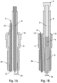
- the dedicated sensing electrode may typically extend from the upper portion of the spark plug, through the insulating body or a housing, such as a threaded metal housing, and into the combustion chamber.
- a sensing circuit can then be connected to the sensing electrode to monitor ion current in an engine's cylinder during combustion.
- the present invention provides a spark plug, comprising: a sparking electrode; an electrically insulating body having a first end and a second end, wherein the electrically insulating body surrounds at least a portion of the sparking electrode, and wherein the sparking electrode exposed at the first end of the electrically insulating body; a housing surrounding a portion of the electrically insulating body, wherein the housing is adapted for mounting the spark plug in an engine cylinder head; a ground electrode connected to the housing, wherein the ground electrode is positioned to create a spark gap between the sparking electrode and the ground electrode; a sensing electrode extending through either the housing or the electrically insulating body, wherein the sensing electrode is electrically isolated from the sparking electrode, wherein a portion of the sensing electrode is exposed near the ground electrode; an insulating material substantially surrounding the sparking electrode along its length; and an electrically conductive shield substantially surrounding the insulating material along its length, the electrically-conductive shield being electrically isolated from the sensing electrode and the sparking electrode,
- the electrically conductive shield is configured to be conductively coupled to ground.
- the top of electrode 6 can be configured to mate with a conventional automotive-type connector in order to allow wiring to a signal processing unit, such as signal processing unit 13 shown in FIG. 9 .
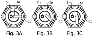
- sensing electrodes 6 are arranged in a land-type configuration.
- the sensing electrodes comprise conductive lands on the spark plug's insulating body with electrically conductive leads or other elements passing through or on body 9 to the top end of the spark plug, where they can be connected as described herein to sensing circuitry.
- the conductive lands that comprise sensing electrodes 6 may also be printed using an electrically conductive material or alloy on the outer surface of body 9.
- multiple sensing electrodes 6, rather than the single element shown in FIGS. 1 and 2 , can also be used.
- electrodes 6 pass through multiple holes in body 9. These holes and electrodes can be also used for multiple purposes, such as fuel injector nozzles or multiple sparking electrodes (as shown in FIG. 6B ). Further, in a configuration with multiple sparking electrodes, some or all of the sparking electrodes can also be used for ion current measurement. One such configuration is shown in FIG. 6B .
- one or more of the sparking electrodes can be used as dedicated ion sensing probes, so that the electrodes are no longer used for sparking, but as discussed above, can be used in conjunction with a signal processing unit such as signal processing unit 13 in FIG. 9 , to measure ion current.
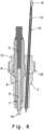
- spark plug bore of the cylinder head in order to allow for an unconventional spark plug, as shown in FIG. 8 .
- the spark plug shown in FIG. 8 can still include all the basic elements discussed above regarding FIG. 1B .
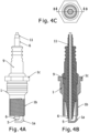
- FIG. 13 additional tubular elements can be added to an arrangement similar to FIG. 4 .
- the sparking electrode 5 is surrounded by insulator 11a, which in turn is surrounded by shield 12, which can be grounded.
- Another insulating layer 11b surrounds shield 12, which is further surrounded by sensing electrode 6, configured here as a tube as in FIGS. 4A-4C .
- shield 12 operates as a shield around the sparking electrode, so that even if multiple sensing electrodes are used, they will be shielded from electromagnetic noise.
- the sparking electrode is also surrounded by an insulator 11 and shield 12.
- a dedicated sensing electrode 6 can pass through the insulating body without the need for a shield immediately surrounding electrode 6, since the sparking electrode is shielded.
- the energy released by the sparking and flame propagation ionizes the fuel-air mixture in the combustion chamber, producing ions and free electrons during the combustion process.
- a DC or AC voltage can be supplied to the sensing electrode 6 to attract ions and electrons and complete the circuit between the insulated electrode and the engine block and/or in-cylinder multiengine components. Electrons and negative ions are attracted to the positively charged electrode tip while positive ions are attracted to the ground electrode or any ground path present in the cylinder. This movement of electrons and ions results in closing the ionization circuit, allowing ion current to flow through a resistor with a known value in the signal processing unit 13. Ion current can be calculated in unit 13 by dividing the measured voltage across the resistor by the resistor value, or by other known means.
- the ion current measured in this manner has a minimum of interference from the voltage generated to cause the ignition spark.
- the ion current path is not the same path caused by the sparking electrode 5, and may flow from the sensing electrode to ground in a different location than the ground electrode of the spark plug.
- the ionization current produced by the dedicated electrode provides a more accurate representation of combustion events within the cylinder, relatively unaffected by the sparking electrode.
- An ion signal can be detected from the very first generation of free ions and electrons inside the combustion chamber through the sensing electrode without the interference of the electromagnetic noise generated by the ignition process. In cases of multi-sparking events where multiple sparks take place within the same engine cycle, the ion current signal can still be captured from start to finish with little or no interference from the ignition event.
- the ion current signal is produced by ionizing the air-fuel mixture species depending on in-cylinder temperature, pressure, equivalence ratio and other operating parameters, it is possible to quantify the ionized species and obtain combustion and emission parameters using the measured ion current signal.
- An in-cylinder combustion ionization signal obtained from the sensor can be used as a feedback signal to provide cycle-by-cycle and cylinder-by-cylinder control over the combustion process in internal combustion engines.
- Such control can be used to help engines meet stringent emission standards and also to achieve improved fuel economy.
- advanced combustion techniques such as lean homogeneous operation or lean stratified operation can be used successfully on engines using combustion feedback derived from the ion current signal. Combustion abnormalities such as engine knocking, misfires or late firing can also be detected with such a signal.
- the claimed embodiments herein enable in-cylinder sensing such as the measurement of ion current signal through a dedicated electrically insulated probe introduced to the combustion chamber, without any interference from the ignition event caused by the high voltage generated by the ignition coils and applied to the sparking electrode to initiate combustion. Sparking operation can occur simultaneously with in-cylinder ion current sensing with minimum or no distortion to the shape of the ion current signal.
- the exemplary, dedicated ion current sensor also has the advantage of eliminating the need to use additional circuitry to separate or isolate the ion current signal from the spark generating voltage.
- the monitoring circuitry in signal processing unit 13 can be in operation continuously. For example, an AC or DC bias signal can be applied to one or more dedicated ion current sensing probes continuously, even when the spark command is present. Thus, as soon as conditions in the cylinder permit ion current flow, it can be measured by the sensing electrode and its associated circuitry in signal processing unit 13.
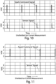
- FIGS. 10 and 11 show data recorded during experiments to test the effect of electromagnetic interference from the sparking event on the ion current signal.
- a time-based ignition command was fed to the ignition system 15 of the spark plug without running the engine.
- a shielded and also an unshielded ion current measurement electrode was used.
- FIG. 10 shows the results using an unshielded ion sensing electrode. A false signal corresponding to spark generation can be clearly seen.
- FIG. 11 shows the voltage measured at the shielded probe, which illustrates the effectiveness of the shield, because little or no voltage caused by unwanted electromagnetic interference is present.
- FIG. 12 illustrates a comparison of signals as they would be present in a running engine with respect to a conventional ionization measurement system and the various embodiments disclosed herein.
- the solid line shows the ion current signal from a shielded, dedicated sensor as discussed and illustrated herein.
- the dotted line illustrates an ionization signal from a conventional spark plug ionization system, where the sparking electrode is also used as an ion current electrode.
- the unwanted current signal is typically present in any circuit arrangement because the same electrode and the same wire is used to carry the sensed current to the detection circuitry. As can be further seen in FIG.
- the signal from the conventional ionization system has significant voltage present that is not due to only ionization within the cylinder, but also due to electromagnetic interference that may need to be accounted for in order to utilize the desired ion current signal.
- the actual ionization current signal is masked by electromagnetic interference present from the sparking voltage.
- FIG. 12 it may be difficult or impossible to determine exactly when combustion (as indicated by ionization current) begins, due to voltage present from other sources in the detection circuit.
Landscapes
- Chemical & Material Sciences (AREA)
- Engineering & Computer Science (AREA)
- Combustion & Propulsion (AREA)
- Mechanical Engineering (AREA)
- General Engineering & Computer Science (AREA)
- Chemical Kinetics & Catalysis (AREA)
- Electrochemistry (AREA)
- Physics & Mathematics (AREA)
- Health & Medical Sciences (AREA)
- Life Sciences & Earth Sciences (AREA)
- Analytical Chemistry (AREA)
- Biochemistry (AREA)
- General Health & Medical Sciences (AREA)
- General Physics & Mathematics (AREA)
- Immunology (AREA)
- Pathology (AREA)
- Ignition Installations For Internal Combustion Engines (AREA)
- Spark Plugs (AREA)
Claims (15)
- Zündkerze, die Folgendes umfasst:eine zündende Elektrode (5);einen elektrisch isolierenden Körper (9), der ein erstes Ende und ein zweites Ende aufweist, wobei der elektrisch isolierende Körper (9) mindestens einen Abschnitt der zündenden Elektrode (5) umgibt und wobei die zündende Elektrode (5) am ersten Ende des elektrisch isolierenden Körpers (9) freiliegt;ein Gehäuse (1), das einen Abschnitt des elektrisch isolierenden Körpers (9) umgibt, wobei das Gehäuse (1) zum Montieren der Zündkerze in einem Motorzylinderkopf angepasst ist;eine Masseelektrode (1a), die mit dem Gehäuse (1) verbunden ist, wobei die Masseelektrode (1a) positioniert ist, um zwischen der zündenden Elektrode (5) und der Masseelektrode (1a) einen Zündspalt zu erstellen;eine Erfassungselektrode (6), die sich entweder durch das Gehäuse (1) oder den elektrisch isolierenden Körper (9) erstreckt, wobei die Erfassungselektrode (6) gegenüber der zündenden Elektrode (5) elektrisch isoliert ist, wobei ein Abschnitt der Erfassungselektrode (6) nahe der Masseelektrode (1a) freiliegt;dadurch gekennzeichnet, dass die Zündkerze ferner Folgendes umfasst:ein Isoliermaterial, das die zündende Elektrode (5) entlang ihrer Länge im Wesentlichen umgibt; undeine elektrisch leitfähige Abschirmung (12), die das Isoliermaterial entlang seiner Länge im Wesentlichen umgibt, wobei die elektrisch leitfähige Abschirmung (12) gegenüber der Erfassungselektrode (6) und der zündenden Elektrode (5) elektrisch isoliert ist, wobei die elektrisch leitfähige Abschirmung (12) eine elektromagnetische Interferenz in der Erfassungselektrode (6) im Wesentlichen reduziert.
- Zündkerze nach Anspruch 1, wobei die Erfassungselektrode (6) gegenüber der Masseelektrode (1a) elektrisch isoliert ist.
- Zündkerze nach Anspruch 1, wobei die elektrisch leitfähige Abschirmung (12) dazu ausgelegt ist, leitend an Masse gekoppelt zu sein.
- Zündkerze nach Anspruch 1, wobei das Gehäuse (1) ein Metall umfasst und wobei die elektrisch leitfähige Abschirmung (12) leitend an das Metall gekoppelt ist.
- Zündkerze nach Anspruch 1, die ferner mindestens eine zweite Erfassungselektrode umfasst, wobei die zweite Erfassungselektrode gegenüber der zündenden Elektrode (5) elektrisch isoliert ist und wobei ein Abschnitt der zweiten Erfassungselektrode am ersten Ende des elektrisch isolierenden Körpers (9) freiliegt.
- Zündkerze nach Anspruch 1, wobei die Erfassungselektrode (6) im Wesentlichen rohrförmig ist und die zündende Elektrode (5) entlang ihrer Länge im Wesentlichen umgibt, die ferner Folgendes umfasst:
ein Isoliermaterial, das zwischen der zündenden Elektrode (5) und der Erfassungselektrode (6) entlang der Länge der zündenden Elektrode (5) angeordnet ist. - Zündkerze nach Anspruch 1, wobei das Gehäuse (1) ein Metall umfasst und wobei sich die Erfassungselektrode (6) durch das Gehäuse (1) erstreckt, die ferner Folgendes umfasst:
Isoliermaterial (11), das die Erfassungselektrode (6) entlang mindestens eines Teils ihrer Länge im Wesentlichen umgibt. - Zündkerze nach Anspruch 1, die ferner mindestens eine zweite Erfassungselektrode umfasst, wobei sich die zweite Erfassungselektrode durch das Metall erstreckt und ein leitfähiges Element umfasst, das am ersten Ende der Zündkerze freiliegt, die ferner Folgendes umfasst:
Isoliermaterial, das die zweite Erfassungselektrode entlang ihrer Länge im Wesentlichen umgibt. - Zündkerze nach Anspruch 1, wobei die Erfassungselektrode (6) ein einzelnes leitfähiges Element umfasst.
- Zündkerze nach Anspruch 1, wobei die Erfassungselektrode (6) eine Vielzahl von leitfähigen Elementen umfasst, vorzugsweise wobei die Vielzahl von leitfähigen Elementen eine leitfähige Stange und einen Widerstand beinhalten.
- Zündkerze nach Anspruch 1, wobei die Erfassungselektrode (6) einen leitfähigen Steg am elektrisch isolierenden Körper (9) umfasst.
- Zündkerze nach Anspruch 11, wobei die Erfassungselektrode (6) eine Vielzahl von Erfassungselektroden umfasst, die als leitfähige Stege ausgelegt sind, vorzugsweise wobei die Zündkerze ferner leitfähige Kabel umfasst, die an die leitfähigen Stege gekoppelt sind und sich durch den elektrisch isolierenden Körper (9) erstrecken.
- Zündkerze nach Anspruch 11, wobei die mindestens eine Erfassungselektrode (6) gegenüber der Masseelektrode (1a) elektrisch isoliert ist.
- Zündkerze nach Anspruch 11, wobei das Gehäuse (1) ein Gewinde (1b) aufweist und ein Metall umfasst.
- Zündkerze nach Anspruch 1, wobei die Zündkerze ferner eine Isolierschicht (11b) umfasst, die die elektrisch leitfähige Abschirmung (12) entlang ihrer Länge im Wesentlichen umgibt, wobei die Erfassungselektrode (6) im Wesentlichen rohrförmig und zwischen der Isolierschicht (11b) und dem elektrisch isolierenden Körper (9) angeordnet ist.
Applications Claiming Priority (2)
| Application Number | Priority Date | Filing Date | Title |
|---|---|---|---|
| US201662425127P | 2016-11-22 | 2016-11-22 | |
| PCT/US2017/063015 WO2018098278A1 (en) | 2016-11-22 | 2017-11-22 | Spark plug combustion ionization sensor |
Publications (3)
| Publication Number | Publication Date |
|---|---|
| EP3545187A1 EP3545187A1 (de) | 2019-10-02 |
| EP3545187A4 EP3545187A4 (de) | 2020-07-22 |
| EP3545187B1 true EP3545187B1 (de) | 2025-03-05 |
Family
ID=62144869
Family Applications (1)
| Application Number | Title | Priority Date | Filing Date |
|---|---|---|---|
| EP17873286.3A Active EP3545187B1 (de) | 2016-11-22 | 2017-11-22 | Verbrennungsionisierungssensor für zündkerze |
Country Status (5)
| Country | Link |
|---|---|
| US (2) | US20180142664A1 (de) |
| EP (1) | EP3545187B1 (de) |
| JP (1) | JP6999186B2 (de) |
| CN (1) | CN110226033A (de) |
| WO (1) | WO2018098278A1 (de) |
Families Citing this family (10)
| Publication number | Priority date | Publication date | Assignee | Title |
|---|---|---|---|---|
| EP3900129B1 (de) * | 2018-12-20 | 2025-04-30 | AI Alpine US Bidco Inc. | System und verfahren zur zündkerzenidentifizierung und motorüberwachung |
| KR102842806B1 (ko) * | 2020-06-17 | 2025-08-05 | 현대자동차 주식회사 | 듀얼 스파크 플러그 |
| US11545816B2 (en) | 2020-11-04 | 2023-01-03 | Federal-Mogul Ignition Gmbh | Spark plug with multiple spark gaps |
| KR102869048B1 (ko) * | 2020-12-11 | 2025-10-10 | 현대자동차 주식회사 | 듀얼 스파크 플러그 |
| KR20230027482A (ko) * | 2021-08-19 | 2023-02-28 | 현대자동차주식회사 | 스파크 플러그 |
| US11621544B1 (en) | 2022-01-14 | 2023-04-04 | Federal-Mogul Ignition Gmbh | Spark plug electrode and method of manufacturing the same |
| US11831130B2 (en) | 2022-03-29 | 2023-11-28 | Federal-Mogul Ignition Gmbh | Spark plug, spark plug electrode, and method of manufacturing the same |
| CN114856879B (zh) * | 2022-04-11 | 2023-04-07 | 哈尔滨工程大学 | 一种可用于燃烧状态在线监测的柴油机喷嘴装置及检测方法 |
| US11837852B1 (en) | 2022-07-27 | 2023-12-05 | Federal-Mogul Ignition Gmbh | Spark plug electrode with electrode tip directly thermally coupled to heat dissipating core and method of manufacturing the same |
| US12191637B1 (en) | 2024-06-14 | 2025-01-07 | Federal-Mogul Ignition Gmbh | Spark plug with cooling features and method of manufacturing the same |
Citations (1)
| Publication number | Priority date | Publication date | Assignee | Title |
|---|---|---|---|---|
| EP0926338B1 (de) * | 1997-12-19 | 2003-08-13 | Renault s.a.s. | Gerät zur Messung des Ionisationsstromes einer Brennkammer |
Family Cites Families (33)
| Publication number | Priority date | Publication date | Assignee | Title |
|---|---|---|---|---|
| US2571507A (en) * | 1950-06-06 | 1951-10-16 | Gen Motors Corp | Pressure indicator |
| US3235763A (en) * | 1960-09-15 | 1966-02-15 | Gen Motors Corp | Igniter plug with spark-sensing probe |
| US3394285A (en) * | 1966-05-20 | 1968-07-23 | Donald E. Lindsay | Two-gap spark plug with series resistor for each gap |
| US4361036A (en) * | 1981-01-08 | 1982-11-30 | Levenson Sol J | Engine analyzer |
| JPS57193777A (en) * | 1981-05-22 | 1982-11-29 | Nissan Motor Co Ltd | Spark ignition type internal combustion device |
| DE3203200A1 (de) * | 1982-01-30 | 1983-08-04 | Bosch Gmbh Robert | Zuendkerze mit sauerstoffsensor |
| DE3828518A1 (de) * | 1988-08-23 | 1990-03-01 | Pierburg Gmbh | Zuendkerze mit integriertem ionenstromsensor |
| KR950004615B1 (ko) * | 1990-09-27 | 1995-05-03 | 미쓰비시덴키 가부시키가이샤 | 내연기관용 점화플러그 |
| JPH04134182A (ja) * | 1990-09-27 | 1992-05-08 | Mitsubishi Electric Corp | 内燃機関用点火プラグ |
| DE4143480C2 (de) * | 1990-09-27 | 1996-06-13 | Mitsubishi Electric Corp | Zündkerze mit einer Ionisationsstrom-Detektorelektrode |
| US5376886A (en) * | 1992-02-06 | 1994-12-27 | Honda Giken Kogyo Kabushiki Kaisha | Ignition distributor cap with misfire detecting capacitor for internal combustion engine |
| US5734094A (en) * | 1993-05-31 | 1998-03-31 | Ngk Spark Plug Co., Ltd. | Ion current detector device for use in an internal combustion engine |
| JPH06338377A (ja) * | 1993-05-31 | 1994-12-06 | Ngk Spark Plug Co Ltd | 内燃機関のイオン電流検出装置 |
| DE4331269C2 (de) | 1993-09-15 | 1995-07-13 | Bosch Gmbh Robert | Verfahren zur Herstellung einer Zündkerze mit Gleitfunkenstrecke und nach den Verfahren hergestellte Zündkerzen |
| JPH08128380A (ja) * | 1994-11-01 | 1996-05-21 | Ngk Spark Plug Co Ltd | ガソリン機関の二次電圧検出器及びその製造方法 |
| US6094990A (en) * | 1998-06-30 | 2000-08-01 | Cooper Automotive Products, Inc. | Spark plug with concentric pressure sensor |
| JP2000068031A (ja) * | 1998-08-18 | 2000-03-03 | Ngk Spark Plug Co Ltd | スパークプラグ及びそのスパークプラグを用いたイオン電流検出機能を持つ点火システム |
| DE10047498A1 (de) | 2000-09-26 | 2002-04-18 | Bosch Gmbh Robert | Zündkerze kompakter Bauart und Herstellungsverfahren |
| JP2002124362A (ja) * | 2000-10-19 | 2002-04-26 | Ngk Spark Plug Co Ltd | 圧力センサ内蔵点火プラグ |
| US7098581B2 (en) * | 2003-09-15 | 2006-08-29 | Cleeves James M | Spark plug |
| US6994073B2 (en) * | 2003-10-31 | 2006-02-07 | Woodward Governor Company | Method and apparatus for detecting ionization signal in diesel and dual mode engines with plasma discharge system |
| US7093421B2 (en) * | 2004-02-10 | 2006-08-22 | General Electric Company | Spark igniter for gas turbine engine |
| US8922102B2 (en) * | 2006-05-12 | 2014-12-30 | Enerpulse, Inc. | Composite spark plug |
| DE102006033480A1 (de) * | 2006-07-19 | 2008-01-24 | Robert Bosch Gmbh | Zündkerze, insbesondere für hohe Brennraumdrücke |
| JP5525454B2 (ja) * | 2008-01-28 | 2014-06-18 | フラム・グループ・アイピー・エルエルシー | 高い位置のねじ山の接地シールド |
| JP5476123B2 (ja) | 2008-04-09 | 2014-04-23 | 日本特殊陶業株式会社 | 内燃機関用スパークプラグ |
| WO2010000709A1 (fr) * | 2008-07-02 | 2010-01-07 | Agc Flat Glass Europe Sa | Alimentation de brûleur à oxygène chaud |
| CH699078A1 (de) * | 2008-07-02 | 2010-01-15 | Kistler Holding Ag | Zündkerze im Grundaufbau mit Drucksensor. |
| JP4619443B2 (ja) | 2009-03-31 | 2011-01-26 | 日本特殊陶業株式会社 | スパークプラグ |
| US8244447B2 (en) | 2010-01-27 | 2012-08-14 | Robert Bosch Gmbh | Spark plug having a thermosensor |
| JP5393830B2 (ja) | 2012-03-28 | 2014-01-22 | 日本特殊陶業株式会社 | スパークプラグ |
| CA2818547C (en) | 2012-09-18 | 2014-08-12 | Ming Zheng | Multi-coil spark ignition system |
| JP5896890B2 (ja) * | 2012-12-10 | 2016-03-30 | 株式会社デンソー | 内燃機関用のスパークプラグ |
-
2017
- 2017-11-22 CN CN201780084048.7A patent/CN110226033A/zh active Pending
- 2017-11-22 WO PCT/US2017/063015 patent/WO2018098278A1/en not_active Ceased
- 2017-11-22 JP JP2019528453A patent/JP6999186B2/ja active Active
- 2017-11-22 EP EP17873286.3A patent/EP3545187B1/de active Active
- 2017-11-22 US US15/820,870 patent/US20180142664A1/en not_active Abandoned
-
2020
- 2020-04-29 US US16/861,578 patent/US10975829B2/en active Active
Patent Citations (1)
| Publication number | Priority date | Publication date | Assignee | Title |
|---|---|---|---|---|
| EP0926338B1 (de) * | 1997-12-19 | 2003-08-13 | Renault s.a.s. | Gerät zur Messung des Ionisationsstromes einer Brennkammer |
Also Published As
| Publication number | Publication date |
|---|---|
| CN110226033A (zh) | 2019-09-10 |
| US20200256308A1 (en) | 2020-08-13 |
| EP3545187A1 (de) | 2019-10-02 |
| JP2020506497A (ja) | 2020-02-27 |
| EP3545187A4 (de) | 2020-07-22 |
| US10975829B2 (en) | 2021-04-13 |
| JP6999186B2 (ja) | 2022-01-18 |
| US20180142664A1 (en) | 2018-05-24 |
| WO2018098278A1 (en) | 2018-05-31 |
Similar Documents
| Publication | Publication Date | Title |
|---|---|---|
| US10975829B2 (en) | Spark plug combustion ionization sensor | |
| KR950003272B1 (ko) | 내연기관의 점화플러그 전류검출장치 | |
| JPS6238652B2 (de) | ||
| EP2171813B1 (de) | Zündvorrichtung für einen verbrennungsmotor | |
| US20070261471A1 (en) | Soot sensor | |
| CN113054535B (zh) | 可用于高频点火系统的火花塞 | |
| JP3900053B2 (ja) | 内燃機関用点火装置 | |
| EP1036268B1 (de) | Verfahren zur messung von partikeleigenschaften in auspuffgasen einer brennkraftmaschine | |
| US6505500B1 (en) | Arrangement for detecting ionization in the combustion chamber of a diesel motor, including associated measurement and calibration devices | |
| JPS61272626A (ja) | 内燃機関の燃焼室内の圧力変動を検出する装置 | |
| US3343366A (en) | Spark discharge monitoring device | |
| US20070159047A1 (en) | Spark plug having excellent capabilities of detecting ion current and suppressing inside sparks | |
| JPS60184972A (ja) | 内燃機関用点火装置 | |
| JP3864871B2 (ja) | 内燃機関用点火装置の検査方法およびその検査装置 | |
| JP2017214917A (ja) | 内燃機関の制御装置及びノック解析方法 | |
| US6655367B2 (en) | Plug-hole-installed ignition coil unit for internal combustion engines | |
| CN104221234A (zh) | 高功率半表面间隙火花塞 | |
| JP2000034969A (ja) | スパークプラグを用いた燃焼状態検出装置 | |
| JP2000068031A (ja) | スパークプラグ及びそのスパークプラグを用いたイオン電流検出機能を持つ点火システム | |
| US2913659A (en) | Testing device for spark plugs | |
| JP2007303285A (ja) | イオン電流検出装置 | |
| JP3663806B2 (ja) | 燃焼装置 | |
| RU2620477C1 (ru) | Устройство измерения, контроля и диагностики процесса сгорания в камере двигателя внутреннего сгорания | |
| WO2021024172A1 (en) | Spark plug and electronic ignition system for an internal engine | |
| JP2022178364A (ja) | スパークプラグ |
Legal Events
| Date | Code | Title | Description |
|---|---|---|---|
| STAA | Information on the status of an ep patent application or granted ep patent |
Free format text: STATUS: THE INTERNATIONAL PUBLICATION HAS BEEN MADE |
|
| PUAI | Public reference made under article 153(3) epc to a published international application that has entered the european phase |
Free format text: ORIGINAL CODE: 0009012 |
|
| STAA | Information on the status of an ep patent application or granted ep patent |
Free format text: STATUS: REQUEST FOR EXAMINATION WAS MADE |
|
| 17P | Request for examination filed |
Effective date: 20190607 |
|
| AK | Designated contracting states |
Kind code of ref document: A1 Designated state(s): AL AT BE BG CH CY CZ DE DK EE ES FI FR GB GR HR HU IE IS IT LI LT LU LV MC MK MT NL NO PL PT RO RS SE SI SK SM TR |
|
| AX | Request for extension of the european patent |
Extension state: BA ME |
|
| DAV | Request for validation of the european patent (deleted) | ||
| DAX | Request for extension of the european patent (deleted) | ||
| A4 | Supplementary search report drawn up and despatched |
Effective date: 20200622 |
|
| RIC1 | Information provided on ipc code assigned before grant |
Ipc: F02P 17/12 20060101ALI20200616BHEP Ipc: H01T 13/06 20060101ALI20200616BHEP Ipc: H01T 13/22 20060101ALI20200616BHEP Ipc: H01T 13/08 20060101ALI20200616BHEP Ipc: F02P 13/00 20060101AFI20200616BHEP Ipc: G01L 23/22 20060101ALI20200616BHEP |
|
| STAA | Information on the status of an ep patent application or granted ep patent |
Free format text: STATUS: EXAMINATION IS IN PROGRESS |
|
| 17Q | First examination report despatched |
Effective date: 20221201 |
|
| GRAP | Despatch of communication of intention to grant a patent |
Free format text: ORIGINAL CODE: EPIDOSNIGR1 |
|
| STAA | Information on the status of an ep patent application or granted ep patent |
Free format text: STATUS: GRANT OF PATENT IS INTENDED |
|
| INTG | Intention to grant announced |
Effective date: 20240927 |
|
| GRAS | Grant fee paid |
Free format text: ORIGINAL CODE: EPIDOSNIGR3 |
|
| GRAA | (expected) grant |
Free format text: ORIGINAL CODE: 0009210 |
|
| STAA | Information on the status of an ep patent application or granted ep patent |
Free format text: STATUS: THE PATENT HAS BEEN GRANTED |
|
| AK | Designated contracting states |
Kind code of ref document: B1 Designated state(s): AL AT BE BG CH CY CZ DE DK EE ES FI FR GB GR HR HU IE IS IT LI LT LU LV MC MK MT NL NO PL PT RO RS SE SI SK SM TR |
|
| REG | Reference to a national code |
Ref country code: GB Ref legal event code: FG4D |
|
| REG | Reference to a national code |
Ref country code: CH Ref legal event code: EP |
|
| REG | Reference to a national code |
Ref country code: DE Ref legal event code: R096 Ref document number: 602017088214 Country of ref document: DE |
|
| REG | Reference to a national code |
Ref country code: IE Ref legal event code: FG4D |
|
| PG25 | Lapsed in a contracting state [announced via postgrant information from national office to epo] |
Ref country code: RS Free format text: LAPSE BECAUSE OF FAILURE TO SUBMIT A TRANSLATION OF THE DESCRIPTION OR TO PAY THE FEE WITHIN THE PRESCRIBED TIME-LIMIT Effective date: 20250605 |
|
| PG25 | Lapsed in a contracting state [announced via postgrant information from national office to epo] |
Ref country code: FI Free format text: LAPSE BECAUSE OF FAILURE TO SUBMIT A TRANSLATION OF THE DESCRIPTION OR TO PAY THE FEE WITHIN THE PRESCRIBED TIME-LIMIT Effective date: 20250305 |
|
| REG | Reference to a national code |
Ref country code: NL Ref legal event code: MP Effective date: 20250305 |
|
| PG25 | Lapsed in a contracting state [announced via postgrant information from national office to epo] |
Ref country code: ES Free format text: LAPSE BECAUSE OF FAILURE TO SUBMIT A TRANSLATION OF THE DESCRIPTION OR TO PAY THE FEE WITHIN THE PRESCRIBED TIME-LIMIT Effective date: 20250305 |
|
| REG | Reference to a national code |
Ref country code: LT Ref legal event code: MG9D |
|
| PG25 | Lapsed in a contracting state [announced via postgrant information from national office to epo] |
Ref country code: NO Free format text: LAPSE BECAUSE OF FAILURE TO SUBMIT A TRANSLATION OF THE DESCRIPTION OR TO PAY THE FEE WITHIN THE PRESCRIBED TIME-LIMIT Effective date: 20250605 |
|
| PG25 | Lapsed in a contracting state [announced via postgrant information from national office to epo] |
Ref country code: HR Free format text: LAPSE BECAUSE OF FAILURE TO SUBMIT A TRANSLATION OF THE DESCRIPTION OR TO PAY THE FEE WITHIN THE PRESCRIBED TIME-LIMIT Effective date: 20250305 |
|
| PG25 | Lapsed in a contracting state [announced via postgrant information from national office to epo] |
Ref country code: LV Free format text: LAPSE BECAUSE OF FAILURE TO SUBMIT A TRANSLATION OF THE DESCRIPTION OR TO PAY THE FEE WITHIN THE PRESCRIBED TIME-LIMIT Effective date: 20250305 |
|
| PG25 | Lapsed in a contracting state [announced via postgrant information from national office to epo] |
Ref country code: BG Free format text: LAPSE BECAUSE OF FAILURE TO SUBMIT A TRANSLATION OF THE DESCRIPTION OR TO PAY THE FEE WITHIN THE PRESCRIBED TIME-LIMIT Effective date: 20250305 Ref country code: GR Free format text: LAPSE BECAUSE OF FAILURE TO SUBMIT A TRANSLATION OF THE DESCRIPTION OR TO PAY THE FEE WITHIN THE PRESCRIBED TIME-LIMIT Effective date: 20250606 |
|
| REG | Reference to a national code |
Ref country code: AT Ref legal event code: MK05 Ref document number: 1773125 Country of ref document: AT Kind code of ref document: T Effective date: 20250305 |
|
| PG25 | Lapsed in a contracting state [announced via postgrant information from national office to epo] |
Ref country code: NL Free format text: LAPSE BECAUSE OF FAILURE TO SUBMIT A TRANSLATION OF THE DESCRIPTION OR TO PAY THE FEE WITHIN THE PRESCRIBED TIME-LIMIT Effective date: 20250305 |
|
| PG25 | Lapsed in a contracting state [announced via postgrant information from national office to epo] |
Ref country code: SE Free format text: LAPSE BECAUSE OF FAILURE TO SUBMIT A TRANSLATION OF THE DESCRIPTION OR TO PAY THE FEE WITHIN THE PRESCRIBED TIME-LIMIT Effective date: 20250305 |
|
| PG25 | Lapsed in a contracting state [announced via postgrant information from national office to epo] |
Ref country code: SM Free format text: LAPSE BECAUSE OF FAILURE TO SUBMIT A TRANSLATION OF THE DESCRIPTION OR TO PAY THE FEE WITHIN THE PRESCRIBED TIME-LIMIT Effective date: 20250305 |
|
| PG25 | Lapsed in a contracting state [announced via postgrant information from national office to epo] |
Ref country code: PT Free format text: LAPSE BECAUSE OF FAILURE TO SUBMIT A TRANSLATION OF THE DESCRIPTION OR TO PAY THE FEE WITHIN THE PRESCRIBED TIME-LIMIT Effective date: 20250707 |
|
| PG25 | Lapsed in a contracting state [announced via postgrant information from national office to epo] |
Ref country code: IT Free format text: LAPSE BECAUSE OF FAILURE TO SUBMIT A TRANSLATION OF THE DESCRIPTION OR TO PAY THE FEE WITHIN THE PRESCRIBED TIME-LIMIT Effective date: 20250305 Ref country code: PL Free format text: LAPSE BECAUSE OF FAILURE TO SUBMIT A TRANSLATION OF THE DESCRIPTION OR TO PAY THE FEE WITHIN THE PRESCRIBED TIME-LIMIT Effective date: 20250305 |
|
| PG25 | Lapsed in a contracting state [announced via postgrant information from national office to epo] |
Ref country code: AT Free format text: LAPSE BECAUSE OF FAILURE TO SUBMIT A TRANSLATION OF THE DESCRIPTION OR TO PAY THE FEE WITHIN THE PRESCRIBED TIME-LIMIT Effective date: 20250305 |
|
| PG25 | Lapsed in a contracting state [announced via postgrant information from national office to epo] |
Ref country code: CZ Free format text: LAPSE BECAUSE OF FAILURE TO SUBMIT A TRANSLATION OF THE DESCRIPTION OR TO PAY THE FEE WITHIN THE PRESCRIBED TIME-LIMIT Effective date: 20250305 Ref country code: EE Free format text: LAPSE BECAUSE OF FAILURE TO SUBMIT A TRANSLATION OF THE DESCRIPTION OR TO PAY THE FEE WITHIN THE PRESCRIBED TIME-LIMIT Effective date: 20250305 |
|
| PG25 | Lapsed in a contracting state [announced via postgrant information from national office to epo] |
Ref country code: RO Free format text: LAPSE BECAUSE OF FAILURE TO SUBMIT A TRANSLATION OF THE DESCRIPTION OR TO PAY THE FEE WITHIN THE PRESCRIBED TIME-LIMIT Effective date: 20250305 |
|
| PG25 | Lapsed in a contracting state [announced via postgrant information from national office to epo] |
Ref country code: SK Free format text: LAPSE BECAUSE OF FAILURE TO SUBMIT A TRANSLATION OF THE DESCRIPTION OR TO PAY THE FEE WITHIN THE PRESCRIBED TIME-LIMIT Effective date: 20250305 |
|
| PG25 | Lapsed in a contracting state [announced via postgrant information from national office to epo] |
Ref country code: IS Free format text: LAPSE BECAUSE OF FAILURE TO SUBMIT A TRANSLATION OF THE DESCRIPTION OR TO PAY THE FEE WITHIN THE PRESCRIBED TIME-LIMIT Effective date: 20250705 |
|
| REG | Reference to a national code |
Ref country code: DE Ref legal event code: R097 Ref document number: 602017088214 Country of ref document: DE |
|
| PGFP | Annual fee paid to national office [announced via postgrant information from national office to epo] |
Ref country code: DE Payment date: 20251127 Year of fee payment: 9 |
|
| PLBE | No opposition filed within time limit |
Free format text: ORIGINAL CODE: 0009261 |
|
| STAA | Information on the status of an ep patent application or granted ep patent |
Free format text: STATUS: NO OPPOSITION FILED WITHIN TIME LIMIT |
|
| PG25 | Lapsed in a contracting state [announced via postgrant information from national office to epo] |
Ref country code: DK Free format text: LAPSE BECAUSE OF FAILURE TO SUBMIT A TRANSLATION OF THE DESCRIPTION OR TO PAY THE FEE WITHIN THE PRESCRIBED TIME-LIMIT Effective date: 20250305 |
|
| REG | Reference to a national code |
Ref country code: CH Ref legal event code: L10 Free format text: ST27 STATUS EVENT CODE: U-0-0-L10-L00 (AS PROVIDED BY THE NATIONAL OFFICE) Effective date: 20260114 |
|
| PGFP | Annual fee paid to national office [announced via postgrant information from national office to epo] |
Ref country code: FR Payment date: 20251127 Year of fee payment: 9 |
|
| 26N | No opposition filed |
Effective date: 20251208 |