EP3545131B1 - Device for supporting a switch rail - Google Patents
Device for supporting a switch rail Download PDFInfo
- Publication number
- EP3545131B1 EP3545131B1 EP17812251.1A EP17812251A EP3545131B1 EP 3545131 B1 EP3545131 B1 EP 3545131B1 EP 17812251 A EP17812251 A EP 17812251A EP 3545131 B1 EP3545131 B1 EP 3545131B1
- Authority
- EP
- European Patent Office
- Prior art keywords
- guide body
- mounting according
- leaf spring
- rail
- slide
- Prior art date
- Legal status (The legal status is an assumption and is not a legal conclusion. Google has not performed a legal analysis and makes no representation as to the accuracy of the status listed.)
- Active
Links
- 238000005096 rolling process Methods 0.000 claims description 31
- 230000001788 irregular Effects 0.000 claims description 2
- 210000002105 tongue Anatomy 0.000 description 45
- 238000003860 storage Methods 0.000 description 9
- 230000002349 favourable effect Effects 0.000 description 2
- 239000000314 lubricant Substances 0.000 description 2
- 238000004519 manufacturing process Methods 0.000 description 2
- 210000005182 tip of the tongue Anatomy 0.000 description 2
- 229910001369 Brass Inorganic materials 0.000 description 1
- 229910000831 Steel Inorganic materials 0.000 description 1
- XAGFODPZIPBFFR-UHFFFAOYSA-N aluminium Chemical compound [Al] XAGFODPZIPBFFR-UHFFFAOYSA-N 0.000 description 1
- 229910052782 aluminium Inorganic materials 0.000 description 1
- 238000005452 bending Methods 0.000 description 1
- 239000010951 brass Substances 0.000 description 1
- 238000010276 construction Methods 0.000 description 1
- 238000004049 embossing Methods 0.000 description 1
- 238000009434 installation Methods 0.000 description 1
- 238000005461 lubrication Methods 0.000 description 1
- 238000012423 maintenance Methods 0.000 description 1
- 230000036316 preload Effects 0.000 description 1
- 238000003825 pressing Methods 0.000 description 1
- 230000000284 resting effect Effects 0.000 description 1
- 239000010959 steel Substances 0.000 description 1
Images


Classifications
-
- E—FIXED CONSTRUCTIONS
- E01—CONSTRUCTION OF ROADS, RAILWAYS, OR BRIDGES
- E01B—PERMANENT WAY; PERMANENT-WAY TOOLS; MACHINES FOR MAKING RAILWAYS OF ALL KINDS
- E01B7/00—Switches; Crossings
- E01B7/02—Tongues; Associated constructions
-
- E—FIXED CONSTRUCTIONS
- E01—CONSTRUCTION OF ROADS, RAILWAYS, OR BRIDGES
- E01B—PERMANENT WAY; PERMANENT-WAY TOOLS; MACHINES FOR MAKING RAILWAYS OF ALL KINDS
- E01B7/00—Switches; Crossings
- E01B7/20—Safety means for switches, e.g. switch point protectors, auxiliary or guiding rail members
-
- E—FIXED CONSTRUCTIONS
- E01—CONSTRUCTION OF ROADS, RAILWAYS, OR BRIDGES
- E01B—PERMANENT WAY; PERMANENT-WAY TOOLS; MACHINES FOR MAKING RAILWAYS OF ALL KINDS
- E01B7/00—Switches; Crossings
- E01B7/26—Lubricating of switches
-
- E—FIXED CONSTRUCTIONS
- E01—CONSTRUCTION OF ROADS, RAILWAYS, OR BRIDGES
- E01B—PERMANENT WAY; PERMANENT-WAY TOOLS; MACHINES FOR MAKING RAILWAYS OF ALL KINDS
- E01B2202/00—Characteristics of moving parts of rail systems, e.g. switches, special frogs, tongues
- E01B2202/04—Nature of the support or bearing
- E01B2202/044—Rolling
- E01B2202/046—Rolling with rolls on fixed part
Definitions
- the invention relates to a device for mounting a tongue rail of a switch, according to the preamble of claim 1.
- Tongue lifting devices as in DE 198 12 795 C1 described, reduce wear and thus save large amounts of lubricant by pressing the tongue rail upwards by a spring and only resting on the sliding chair when a train passes over it.
- a disadvantage is the still considerable actuating force, since the frictional force is largely independent of the area.
- connection to the threshold or the switch base plate requires precise adjustment at at least two points.
- EP 2 995 718 A1 discloses a device for mounting a tongue rail of a switch, comprising a rolling element and a cantilevered leaf spring which can be pretensioned to the tongue rail and on which the tongue rail is arranged so as to be displaceable by means of the rolling element.
- the leaf spring is arranged in a guide body, which can be fastened to a stock rail of the switch.
- the tongue rail is stored in several places.
- the tongue stroke and the distance to the stock rail are different for the different bearings.
- the tongue stroke is small near the tongue root and the distance to the stock rail is large.
- the tongue stroke is large and the distance in the adjacent position is zero.
- the object of the present invention is to expand the function of conventional bearings and to offer a much simpler, and therefore also quick-to-assemble and inexpensive device for storing tongue rails.
- this object is achieved by a device having the features of claim 1.
- tongue storage can be considerably simplified.
- the required actuating force is significantly lower than with conventional storage of switch tongues or tongue rails. This significantly reduces the switching force.
- the forces to be exerted by the drives are significantly lower, which protects them.
- the actuator could be made significantly smaller.
- the adjustability of the position of the leaf spring bearing in the guide body via a slide proves to be particularly advantageous, as a result of which the device can be used universally and production and storage are greatly simplified. This enables the position of the rolling element to be adjusted in a simple manner and be adapted to the circumstances with high accuracy. Regardless of the position of the slide in the guide body and thus the position of the Rolling body compared to the stock rail, the spring length, and thus the mechanical or elastic properties remain constant.
- the slide can be fixed in the guide body both positively and frictionally, the frictional variant comprising splines, for example. This has the advantage of a stepless adjustment.
- the slide can be fastened to the guide body via a connection which consists of a surface of greater hardness with a regular or irregular surface structure and a counter surface of lower hardness.
- the harder surface can be made of steel, for example, and the counter surface can be made of brass or aluminum, for example. Security against loosening is achieved by embossing the surface structure of the harder surface into the softer counter surface when the screw is tightened.
- teeth can be provided both on the slide and in the guide body, as a result of which the position of the slide is permanently fixed in the direction of adjustment, which is preferably fastened by screwing. An adjustment of the cantilever over the life of the device by vibration, for example, is thus prevented. It proves to be particularly favorable if the toothing is arranged on one side of the guide body or the matching counterpart on one side of the slide. A secure connection can be achieved if the screw connection is arranged on the same side as the toothing.
- the position of the guide body relative to the stock rail can also be changed.
- the clamping body which represents the connection to the stock rail, and on the guide body, with which the clamping body and guide body can be screwed together in different positions. This enables a rough adjustment, the fine adjustment can be carried out by moving the slide in the guide body.
- Another possible embodiment variant provides that the clamps are arranged directly on the guide body in order to obtain a simpler system from fewer individual parts.
- the contact force between the tongue rail and sliding chair can be reduced as desired.
- the tongue When the tongue is rolled up, it can be lifted entirely from the sliding chair, which completely eliminates the contact force when sliding over it.
- the preload can be adjusted via the height of the rolling element in relation to the roller block.
- a height adjustment of the rolling element in a roller block, which forms the connection between the rolling element and the leaf spring, can therefore be particularly advantageous for precise adjustment.
- the use of screws for adjustment proves to be advantageous.
- roller block is attached to the leaf spring by means of a dowel with a rotational degree of freedom that allows the roller block with rolling element to pivot slightly about a vertical axis.
- Attachment to the base of the stock rail enables storage that is independent of different sleepers or sliding chair geometries. This can be achieved particularly cheaply by a clamp connection.
- a rigid clamp which is preferably formed in one piece by the clamp body, and a screw clamp, which can be screwed to the clamp body, are particularly suitable for this purpose.
- a universal use can be achieved by several receptacles in a row for the screw terminal and a corresponding toothing. During installation, the distance between the clamps can thus be adapted to the existing rail system, in particular the width of the base of the stock rail.
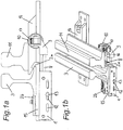
- a guide body 1 is fastened to a stock rail 3 via a clamp body 15 of a device according to the invention by means of clamps 2a, 2b.
- the guide body 1 is box-shaped in a U-shape and firmly connected to terminals 2a, 2b by means of a clamping body, a rigid terminal 2a and a screw terminal 2b being present.
- the rigid clamp 2a is arranged on the clamp body 15, to which a screw clamp 2b is screwed.
- the guide body 1 is screwed to the clamping body 15.
- a carriage 4 which in turn can be displaced and fastened in the longitudinal direction within the guide body 1.
- elongated holes 12 on a side wall of the guide body 1 for fixing the slide 4 with a screw 13.
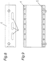
- a rack 5 is provided on the inner wall of the guide body 1.
- Rack pieces 6 engaging in the rack 5 are arranged on the side of the slide 4.
- the relative position of the clamping body 15 to the slide 4 can thus be roughly defined by means of the connection between the clamping body 15 and the guide body 1, a fine adjustment is possible via the connection between the guide body 1 and the slide 4.
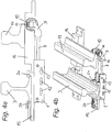
- Both the distance between the stock rail 3 and a tongue rail 11 and the tongue stroke of the tongue rail 11 differ according to the position of the storage within the switch. In the vicinity of the tongue root, the range of movement of the tongue rail 11 is small and the distance to the stock rail 3 is large.
- Such a structure is in the 3a and b , such as 4a and b to see.
- 3a and b show the tongue rail 11 in a position adjacent to the stock rail 3.
- 4a and b show the tongue rail 11 in a position remote from the stock rail 3.
- the distance between the middle of the stock rail and the edge of the tongue (contact with the roller) differs depending on the type of turnout.
- FIGS Fig. 1a, b A device according to the invention in a region closer to the tip of the tongue is shown in FIGS Fig. 1a, b in the position of the stock rail 3 and 2a, b shown in the position remote from the stock rail 3.
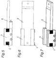
- a leaf spring 8 is attached to the slide 4.
- the surface of the guide body facing away from the stock rail 3 is held at a distance A by the slide 4. This is dimensioned such that the leaf spring 8 does not rest on the guide body 1 even at maximum load. As a result, the effective length of the leaf spring 8 and thus the spring properties remain constant.
- Another end of the leaf spring 8 is connected to a roller body 10 via a roller block 9 and set screws 17.
- the base of the tongue rail 11 lies on this.
- the roller block 9 is connected to the leaf spring 8 by a vertical dowel pin 16. This allows a slight rotation about its axis, as a result of which the tolerances of the rolling elements 10 align at the correct angle to the contact surface of the tongue rail 11.
- set screws 17 are also arranged in the roller block, with which the rolling element 10 is adjustable in height.
- the pretensioning of the tongue rail 11 can be adapted to the requirements.
- the roughly required rolling element position is initially set via the clamping body 15 - guide body 1 connection. This can be done at the factory in the form of product variants consisting of the same parts, or at the construction site at the start of assembly.
- the entire device is clamped to the stock rail 3 via the clamps 2a, 2b.
- the slide 4 is fine-adjusted in the guide body 1, and thus also the position of the roller body 10 relative to the stock rail 3.
- the position of the slide 4 is fixed with the screw 13, through the rack 5 and the rack pieces 6 an adjustment, for example by vibration , leaning forward.
- the entire system is biased against the tongue rail 11.
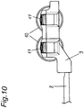
- Fig. 10 shows an alternative embodiment with two roles. This can be used, for example, when the tongue stroke is greater than the width of the foot of the tongue rail plus the roll-up path.
Landscapes
- Engineering & Computer Science (AREA)
- Mechanical Engineering (AREA)
- Architecture (AREA)
- Civil Engineering (AREA)
- Structural Engineering (AREA)
- Railway Tracks (AREA)
- Bearings For Parts Moving Linearly (AREA)
Description
Die Erfindung betrifft eine Vorrichtung zur Lagerung einer Zungenschiene einer Weiche, nach dem Oberbegriff des Anspruchs 1.The invention relates to a device for mounting a tongue rail of a switch, according to the preamble of
Herkömmliche Weichen für Schienenfahrzeuge weisen in der Regel gleitgelagerte Schienenzungen auf. Bei einer Verstellung der Weichenposition treten deshalb beachtliche Stellkräfte auf. Aufgrund notwendiger Schmierung wird der umliegende Untergrund verseucht und es ist regelmäßiges Aufbringen von Schmiermittel erforderlich. Bei Weichen ohne Umstellhilfen werden die Gleitflächen per Hand geschmiert, um eine sichere Funktion zu gewährleisten. Dadurch besteht regelmäßig ein erhöhter logistischer Aufwand. Darüber hinaus bleibt immer ein Restrisiko, wenn sich Personen im Gleisbereich befinden.Conventional switches for rail vehicles generally have slide-mounted rail tongues. Considerable actuating forces therefore occur when the switch position is adjusted. The surrounding subsurface is contaminated due to the need for lubrication and lubricant must be applied regularly. In the case of switches without changeover aids, the sliding surfaces are lubricated by hand to ensure reliable functioning. As a result, there is regularly an increased logistical effort. In addition, there is always a residual risk if there are people in the track area.
Zungenhebevorrichtungen, wie in
Aus diesen Gründen werden zunehmend Wälzlager verwendet. Da die Wälzkörper den sehr hohen Belastungen bei der Überfahrt eines Schienenfahrzeugs nicht standhalten können, sind spezielle konstruktive Maßnahmen zu ergreifen. Eine Möglichkeit besteht darin, wie in
Ein anderer Lösungsansatz ist in
In der Praxis hat sich jedoch die aufwändige Montage als Problem dargestellt. Die Verbindung mit der Schwelle bzw. der Weichengrundplatte benötigt eine präzise Adjustierung an mindestens zwei Punkten.In practice, however, the complex assembly has proven to be a problem. The connection to the threshold or the switch base plate requires precise adjustment at at least two points.
Eine weitere bekannte Lösung ist in der
Bei üblichen Weichen ist die Zungenschiene an mehreren Stellen gelagert. Dabei ist bei den unterschiedlichen Lagern sowohl der Zungenhub, als auch der Abstand zur Backenschiene unterschiedlich. Der Zungenhub ist in der Nähe der Zungenwurzel gering und der Abstand zur Backenschiene groß. Am anderen Ende der Zungenschiene ist der Zungenhub groß, und der Abstand in der anliegenden Position null.With conventional switches, the tongue rail is stored in several places. The tongue stroke and the distance to the stock rail are different for the different bearings. The tongue stroke is small near the tongue root and the distance to the stock rail is large. At the other end of the tongue rail, the tongue stroke is large and the distance in the adjacent position is zero.
Dies erfordert verschiedene Lagertypen für eine Weiche, was eine komplizierte Lagerhaltung erfordert. Bei modernen Hochgeschwindigkeitsweichen ist dieses Problem noch viel deutlicher. Hier sind die Biegeradien so groß, dass eine Lagerung an mehreren Punkten notwendig ist. In der Praxis wäre deshalb eine vor Ort einfach für die zuvor beschriebenen veränderlichen Maße konfigurierbare Lagerung von Vorteil.This requires different types of storage for a switch, which requires complicated storage. This problem is much clearer with modern high-speed switches. Here the bending radii are so large that storage at several points is necessary. In practice, it would therefore be advantageous to have storage that is easily configurable on site for the variable dimensions described above.
Aufgabe der vorliegenden Erfindung ist, die Funktion herkömmlicher Lager zu erweitern und eine wesentlich einfachere, und somit auch schnell montierbare und preisgünstige Vorrichtung zur Lagerung von Zungenschienen zu bieten.The object of the present invention is to expand the function of conventional bearings and to offer a much simpler, and therefore also quick-to-assemble and inexpensive device for storing tongue rails.
Erfindungsgemäß wird diese Aufgabe durch eine Vorrichtung mit den Merkmalen des Anspruchs 1 gelöst. Dadurch kann die Zungenlagerung wesentlich vereinfacht werden. Weiters ist die erforderliche Stellkraft aufgrund der geringeren Rollreibung über den gesamten Hubweg wesentlich geringer, als bei der konventionellen Lagerung von Weichenzungen bzw. Zungenschienen. Dadurch werden die Stellkräfte der Weiche deutlich reduziert. Durch die Entlastung eines allfällig vorgesehenen Gleitstuhls muss dieser nicht mehr regelmäßig geschmiert werden. Dadurch werden Wartungsaufwand und -kosten eingespart. Die von den Antrieben aufzubringenden Kräfte sind dadurch wesentlich geringer, wodurch diese geschont werden. Darüber hinaus könnte das Stellelement dadurch deutlich kleiner ausgeführt werden.According to the invention, this object is achieved by a device having the features of
Besonders vorteilhaft erweist sich die Verstellbarkeit der Position der Blattfederlagerung im Führungskörper über einen Schlitten, wodurch die Vorrichtung universell einsetzbar ist, und die Produktion und Lagerhaltung stark vereinfacht wird. Dadurch kann die Position des Wälzkörpers auf einfache Weise und mit hoher Genauigkeit den Gegebenheiten angepasst werden. Unabhängig von der Position des Schlittens im Führungskörper und somit der Position des Wälzkörpers gegenüber der Backenschiene, bleiben die Federlänge, und somit die mechanischen bzw. elastischen Eigenschaften konstant.The adjustability of the position of the leaf spring bearing in the guide body via a slide proves to be particularly advantageous, as a result of which the device can be used universally and production and storage are greatly simplified. This enables the position of the rolling element to be adjusted in a simple manner and be adapted to the circumstances with high accuracy. Regardless of the position of the slide in the guide body and thus the position of the Rolling body compared to the stock rail, the spring length, and thus the mechanical or elastic properties remain constant.
Der Schlitten kann im Führungskörper sowohl formschlüssig als auch reibschlüssig festgelegt werden, wobei die reibschlüssige Variante beispielsweise Keilnuten umfasst. Dies hat den Vorteil einer stufenlosen Verstellmöglichkeit.The slide can be fixed in the guide body both positively and frictionally, the frictional variant comprising splines, for example. This has the advantage of a stepless adjustment.
Es kann auch vorgesehen sein, dass der Schlitten über eine Verbindung am Führungskörper befestigbar ist, die aus einer Fläche größerer Härte mit regelmäßiger oder unregelmäßiger Oberflächenstruktur und einer Gegenfläche geringerer Härte besteht. Die härtere Fläche kann dabei beispielsweise aus Stahl und die Gegenfläche beispielsweise aus Messing oder Aluminium hergestellt sein. Eine Sicherheit gegen Lockerung wird dadurch erreicht, dass die Oberflächenstruktur der härteren Fläche beim Anziehen der Schraube in die weichere Gegenfläche eingeprägt wird.It can also be provided that the slide can be fastened to the guide body via a connection which consists of a surface of greater hardness with a regular or irregular surface structure and a counter surface of lower hardness. The harder surface can be made of steel, for example, and the counter surface can be made of brass or aluminum, for example. Security against loosening is achieved by embossing the surface structure of the harder surface into the softer counter surface when the screw is tightened.
Im Rahmen einer formschlüssigen Verbindung kann eine Verzahnung sowohl am Schlitten, als auch im Führungskörper vorgesehen sein, wodurch die Position des Schlittens in Verstellrichtung dauerhaft fixiert wird, welche vorzugsweise durch Verschraubung befestigt ist. Es wird somit einer Verstellung der Auskragung über die Lebensdauer der Vorrichtung durch beispielsweise Vibration vorgebeugt. Besonders günstig erweist es sich, wenn die Verzahnung an einer Seite des Führungskörpers angeordnet ist bzw. das passende Gegenstück an einer Seite des Schlittens. Eine sichere Verbindung kann erreicht werden, wenn die Verschraubung an derselben Seite wie die Verzahnung angeordnet ist.As part of a positive connection, teeth can be provided both on the slide and in the guide body, as a result of which the position of the slide is permanently fixed in the direction of adjustment, which is preferably fastened by screwing. An adjustment of the cantilever over the life of the device by vibration, for example, is thus prevented. It proves to be particularly favorable if the toothing is arranged on one side of the guide body or the matching counterpart on one side of the slide. A secure connection can be achieved if the screw connection is arranged on the same side as the toothing.
Um einen besonders großen Verstellbereich zu ermöglichen, kann auch die Position des Führungskörpers gegenüber der Backenschiene verändert werden. Dazu sind sowohl am Klemmkörper, welcher die Verbindung zur Backenschiene darstellt, als auch am Führungskörper mehrere Bohrungen vorhanden, mit denen Klemmkörper und Führungskörper miteinander in verschiedenen Positionen verschraubbar sind. Dies ermöglicht eine Grobeinstellung, die Feinjustierung kann durch Verschieben des Schlittens in Führungskörper vorgenommen werden.In order to allow a particularly large adjustment range, the position of the guide body relative to the stock rail can also be changed. For this purpose, there are several bores on the clamping body, which represents the connection to the stock rail, and on the guide body, with which the clamping body and guide body can be screwed together in different positions. This enables a rough adjustment, the fine adjustment can be carried out by moving the slide in the guide body.
Eine andere mögliche Ausführungsvariante sieht vor, dass die Klemmen direkt am Führungskörper angeordnet sind, um ein einfacheres System aus weniger Einzelteilen zu erhalten.Another possible embodiment variant provides that the clamps are arranged directly on the guide body in order to obtain a simpler system from fewer individual parts.
Wenn die Blattfeder zur Zungenschiene vorgespannt ist, kann im anliegenden Zustand die Kontaktkraft zwischen Zungenschiene und Gleitstuhl beliebig reduziert werden. Bei aufgerollter Zunge kann diese gänzlich vom Gleitstuhl aufgehoben werden, wodurch die Kontaktkraft beim Gleiten über diesen gänzlich entfällt.If the leaf spring is pretensioned to the tongue rail, the contact force between the tongue rail and sliding chair can be reduced as desired. When the tongue is rolled up, it can be lifted entirely from the sliding chair, which completely eliminates the contact force when sliding over it.
Die Vorspannung kann über die Höhe des Wälzkörpers gegenüber dem Rollenbock eingestellt werden. Für eine genaue Adjustierung kann deshalb eine Höhenverstellung des Wälzkörpers in einem Rollenbock, der die Verbindung zwischen dem Wälzkörper und der Blattfeder bildet, von besonderem Vorteil sein. Insbesondere die Verwendung von Schrauben zur Einstellung erweist sich als vorteilhaft.The preload can be adjusted via the height of the rolling element in relation to the roller block. A height adjustment of the rolling element in a roller block, which forms the connection between the rolling element and the leaf spring, can therefore be particularly advantageous for precise adjustment. In particular, the use of screws for adjustment proves to be advantageous.
Bestmöglicher Linienkontakt zwischen Wälzkörper und Zungenfußkante kann erreicht werden, wenn der Rollenbock mit der Blattfeder über einen Passstift mit Rotationsfreiheitsgrad befestigt ist, der eine geringfügige Schwenkung des Rollenbocks mit Wälzkörper um eine vertikale Achse ermöglicht.The best possible line contact between the rolling element and the tongue base edge can be achieved if the roller block is attached to the leaf spring by means of a dowel with a rotational degree of freedom that allows the roller block with rolling element to pivot slightly about a vertical axis.
Durch Befestigung am Fuß der Backenschiene wird eine von unterschiedlichen Schwellen bzw. Gleitstuhlgeometrien unabhängige Lagerung ermöglicht. Dies kann besonders günstig durch eine Klemmverbindung erreicht werden. Dazu eignet sich besonders gut eine starre Klemme, die vorzugsweise einstückig vom Klemmkörper gebildet wird, und eine Schraubklemme, die mit dem Klemmkörper verschraubbar ist. Ein universeller Einsatz kann durch mehrere Aufnahmen in einer Reihe für die Schraubklemme und eine entsprechende Verzahnung erreicht werden. Beim Einbau kann somit der Abstand der Klemmen an das vorhandene Schienensystem, insbesondere die Breite des Fußes der Backenschiene angepasst werden.Attachment to the base of the stock rail enables storage that is independent of different sleepers or sliding chair geometries. This can be achieved particularly cheaply by a clamp connection. A rigid clamp, which is preferably formed in one piece by the clamp body, and a screw clamp, which can be screwed to the clamp body, are particularly suitable for this purpose. A universal use can be achieved by several receptacles in a row for the screw terminal and a corresponding toothing. During installation, the distance between the clamps can thus be adapted to the existing rail system, in particular the width of the base of the stock rail.
An den meisten Positionen ist die Verwendung von genau einem Wälzkörper vorgesehen. Bei großem Zungenhub ist jedoch ein zweiter Wälzkörper erforderlich, um eine Abstützung über den gesamten Bewegungsbereich zu gewährleisten, d.h. dass die aufgerollte Zunge immer auf zumindest einer Rolle aufliegt.In most positions, the use of exactly one rolling element is intended. With a large tongue stroke, however, a second rolling element is required to ensure support over the entire range of motion, i.e. that the rolled tongue always rests on at least one roller.
Eine günstige Fertigung ist durch den rechteckigen Querschnitt des Führungskörpers gewährleistet.Favorable production is ensured by the rectangular cross section of the guide body.
In der Folge wird ein Ausführungsbeispiel der Erfindung anhand der Figuren näher erläutert. Es zeigen:
- Fig. 1a
- eine erfindungsgemäße Vorrichtung in einer Seitenansicht in einer an der Backenschiene anliegenden Position;
- Fig. 1b
- die Vorrichtung in einem Schrägriss in einer an der Backenschiene anliegenden Position;
- Fig. 2a
- die Vorrichtung in einer Seitenansicht in einer von der Backenschiene entfernten Position;
- Fig. 2b
- die Vorrichtung in einem Schrägriss in einer von der Backenschiene entfernten Position;
- Fig. 3a
- eine erfindungsgemäße Vorrichtung an einer anderen Stelle der Weiche in einer Seitenansicht in einer, an der Backenschiene anliegenden Position;
- Fig. 3b
- die Vorrichtung in einem Schrägriss in einer an der Backenschiene anliegenden Position;
- Fig. 4a
- die Vorrichtung in einer Seitenansicht in einer von der Backenschiene entfernten Position;
- Fig. 4b
- die Vorrichtung in einem Schrägriss in einer von der Backenschiene entfernten Position;
- Fig. 5
- den Schlitten mit Blattfeder in einer Seitenansicht;
- Fig. 6
- den Schlitten mit Blattfeder in einem Grundriss;
- Fig. 7
- der Schlitten mit Blattfeder in einem Schrägriss;
- Fig. 8
- der Führungskörper in einer Seitenansicht;
- Fig. 9
- der Führungskörper in einem Grundriss; und
- Fig. 10
- einen Rollenbock mit Wälzkörpern einer alternativen Ausgestaltung der Vorrichtung mit zwei Wälzkörpern in einer Seitenansicht.
- Fig. 1a
- a device according to the invention in a side view in a position against the stock rail;
- Fig. 1b
- the device in an oblique crack in a position adjacent to the stock rail;
- Fig. 2a
- the device in a side view in a position removed from the stock rail;
- Fig. 2b
- the device in an oblique crack in a position removed from the stock rail;
- Fig. 3a
- a device according to the invention at another point of the switch in a side view in a position against the stock rail;
- Fig. 3b
- the device in an oblique crack in a position adjacent to the stock rail;
- Fig. 4a
- the device in a side view in a position removed from the stock rail;
- Fig. 4b
- the device in an oblique crack in a position removed from the stock rail;
- Fig. 5
- the carriage with leaf spring in a side view;
- Fig. 6
- the carriage with leaf spring in a floor plan;
- Fig. 7
- the carriage with leaf spring in a diagonal tear;
- Fig. 8
- the guide body in a side view;
- Fig. 9
- the guide body in a floor plan; and
- Fig. 10
- a roller block with rolling elements of an alternative embodiment of the device with two rolling elements in a side view.
Ein Führungskörper 1 ist über einen Klemmkörper 15 einer erfindungsgemäßen Vorrichtung mittels Klemmen 2a, 2b an einer Backenschiene 3 befestigt. Der Führungskörper 1 ist schachtelartig in U-Form ausgebildet und fest mit Klemmen 2a, 2b über einen Klemmkörper verbunden, wobei eine starre Klemme 2a und eine Schraubklemme 2b vorhanden sind. Die starre Klemme 2a ist an dem Klemmkörper 15 angeordnet, mit welchem eine Schraubklemme 2b verschraubt ist. Der Führungskörper 1 ist mit dem Klemmkörper 15 verschraubt. Dabei sind sowohl im Klemmkörper 15, als auch im Führungskörper 1 mehrere Bohrungen vorhanden, um eine Befestigung in verschiedenen Positionen entlang einer Längsachse des Führungskörpers 1 zu ermöglichen.A
Im Führungskörper 1 befindet sich ein Schlitten 4, welcher wiederum in Längsrichtung innerhalb des Führungskörpers 1 verschiebbar und befestigbar ist. Dazu befinden sich an einer Seitenwand des Führungskörpers 1 Langlöcher 12 zur Fixierung des Schlittens 4 mit einer Schraube 13. An der Innenwand des Führungskörpers 1 ist eine Zahnstange 5 zur Arretierung der Position des Schlittens 4 vorgesehen. In die Zahnstange 5 eingreifende Zahnstangenstücke 6 sind an der Seite des Schlittens 4 angeordnet.In the
Die relative Position des Klemmkörpers 15 zu dem Schlitten 4 kann also grob mittels der Verbindung zwischen Klemmkörper 15 und Führungskörper 1 definiert werden, eine Feinjustierung ist über die Verbindung zwischen Führungskörper 1 und Schlitten 4 möglich.The relative position of the clamping
Sowohl der der Abstand zwischen Backenschiene 3 und einer Zungenschiene 11, als auch der Zungenhub der Zungenschiene 11 ist nach Position der Lagerung innerhalb der Weiche unterschiedlich. In der Nähe der Zungenwurzel ist der Bewegungsbereich der Zungenschiene 11 gering und der Abstand zur Backenschiene 3 groß. Ein solcher Aufbau ist in den
Über die gesamte Zungenlänge ist der Abstand zwischen Backenschienenmittelebene und Zungenfußkante (Kontakt zur Rolle) in Abhängigkeit vom Weichentyp unterschiedlich.Over the entire length of the tongue, the distance between the middle of the stock rail and the edge of the tongue (contact with the roller) differs depending on the type of turnout.
In Richtung der Zungenspitze der Zungenschiene 11 wird der Zungenhub immer größer. Eine erfindungsgemäße Vorrichtung in einem, der Zungenspitze näheren Bereich wird in den
Am Schlitten 4 ist ein Ende einer Blattfeder 8 befestigt. Die der Backenschiene 3 abgewandte, Fläche des Führungskörpers wird vom Schlitten 4 in einem Abstand A gehalten. Dieser ist so bemessen, dass die Blattfeder 8 auch bei maximaler Belastung nicht am Führungskörper 1 aufliegt. Dadurch bleiben die wirksame Länge der Blattfeder 8, und somit die Federeigenschaften, konstant.One end of a
Ein anderes Ende der Blattfeder 8 ist über einen Rollenbock 9 und Stellschrauben 17 mit einem Wälzkörper 10 verbunden. Auf diesem liegt der Fuß der Zungenschiene 11 auf.Another end of the
Die Verbindung des Rollenbocks 9 mit der Blattfeder 8 erfolgt durch einen vertikalen Passstift 16. Dieser ermöglicht eine geringfügige Drehung um seine Achse, wodurch sich auch bei Toleranzen der Wälzkörper 10 im richtigen Winkel zur Kontaktfläche der Zungenschiene 11 ausrichtet.The
Für eine optimale Adjustierung sind außerdem im Rollenbock 9 Stellschrauben 17 angeordnet, mit denen der Wälzkörper 10 höhenverstellbar ist. Dadurch kann die Vorspannung der Zungenschiene 11 an die Erfordernisse angepasst werden.For
Durch die Vorspannung der Blattfeder 8 wird die Zungenschiene 11 von einem Gleitstuhl 14 bereits in einer sehr frühen Phase der Bewegung aufgehoben. Dadurch muss, bei Verstellung der Weiche, nur die geringere Rollreibung der Wälzkörper 10 überwunden werden, nicht jedoch die Gleitreibung der Gleitstühle.By pretensioning the
Bei Überfahrt eines Zuges liegt die Zungenschiene 11 auf dem Gleitstuhl 14 auf, über den der Großteil der Lastkraft mit Ausnahme der Vorspannkraft übertragen wird.When a train passes, the
Bei der Montage des Systems wird zu Beginn die ungefähr benötigte Wälzkörperposition über die Klemmkörper 15 - Führungskörper 1 Verbindung eingestellt. Dies kann sowohl werksseitig in Form von Produktvarianten, bestehend aus den gleichen Teilen, oder baustellenseitig zu Beginn der Montage erfolgen. Als nächstes wird die gesamte Vorrichtung an der Backenschiene 3 über die Klemmen 2a, 2b festgeklemmt. Nun erfolgt die Feinjustierung des Schlittens 4 im Führungskörper 1, und damit auch die Position des Wälzkörpers 10 zur Backenschiene 3. Die Position des Schlittens 4 wird mit der Schraube 13 fixiert, durch die Zahnstange 5 und den Zahnstangenstücken 6 wird einer Verstellung, durch beispielsweise Vibration, vorgebeugt. Zuletzt wird das gesamte System gegen die Zungenschiene 11 vorgespannt.When assembling the system, the roughly required rolling element position is initially set via the clamping body 15 -
Claims (15)
- Device for mounting a switch rail (11) of a switch, having a rolling element (10), a guide body (1) and a projecting leaf spring (8) which can be pretensioned towards the switch rail (11) and on which the switch rail (11) is arranged so as to be displaceable by means of the rolling element (10), wherein the leaf spring (8) is arranged in the guide body (1), which can be fastened to a stock rail (3), characterised in that the leaf spring (8) is arranged in the guide body (1) so as to be adjustable in its longitudinal direction.
- Device for mounting according to claim 1, characterised in that the leaf spring (8) is fixed in the guide body (1) at the one end remote from the rolling element (10) by means of a slide (4).
- Device for mounting according to one of claims 1 or 2, characterised in that the slide (4) is fastened to the guide body (1) via a frictional connection.
- Device for mounting according to one of claims 1 or 2, characterised in that the slide (4) is fastened to the guide body (1) via a connection consisting of a surface of greater hardness with a surface structure and a counter-surface of lesser hardness, wherein the regular or irregular surface structure of the surface of greater hardness is impressed into the softer counter-surface in the course of the fastening.
- Device for mounting according to one of claims 1 or 2, characterised in that the slide (4) is fastened to the guide body (1) via a positive connection.
- Device for mounting according to claim 5, characterised in that the positive connection is formed as a toothed region which is arranged on a side wall of the guide body (1) and on the slide (4), and in that preferably the screw connection is also arranged on this side.
- Device for mounting according to one of claims 1 to 6, characterised in that a clamp body (15) is fastened by means of clamps (2a, 2b) to a foot of the stock rail (3) when mounted.
- Device for mounting according to claim 7, characterised in that at least one of the clamps (2a, 2b) is firmly connected to the clamp body (15) at different positions.
- Device for mounting according to claim 7 or 8, characterised in that the clamp body (15) can be firmly connected to the guide body (1) in different positions.
- Device for mounting according to one of claims 1 to 9, characterised in that the guide body (1) has a rectangular cross-section.
- Device for mounting according to one of claims 1 to 10, characterised in that the side of the leaf spring (8) facing away from the stock rail (3) has a distance (A) from a web part of the guide body (1) facing the stock rail (3).
- Device for mounting according to one of claims 1 to 11, characterised in that the rolling element (10) is fastened to the leaf spring (8) so as to be height-adjustable via a roller block (9), wherein the rolling element (10) is height-adjustable on the roller block (9) preferably with at least one screw.
- Device for mounting according to claim 12, characterised in that the roller block (9) is arranged on the leaf spring (8) so as to be pivotable about a vertical axis.
- Device for mounting according to one of claims 12 to 13, characterised in that exactly one rolling element (10) is arranged on the roller block (9).
- Device for mounting according to one of claims 12 to 13, characterised in that two rolling elements (10) with preferably parallel axes are arranged on the roller block (9).
Applications Claiming Priority (2)
| Application Number | Priority Date | Filing Date | Title |
|---|---|---|---|
| ATA51060/2016A AT519432B1 (en) | 2016-11-23 | 2016-11-23 | DEVICE FOR STORING A TISSUE RAIL |
| PCT/AT2017/060306 WO2018094434A1 (en) | 2016-11-23 | 2017-11-21 | Device for supporting a switch rail |
Publications (2)
| Publication Number | Publication Date |
|---|---|
| EP3545131A1 EP3545131A1 (en) | 2019-10-02 |
| EP3545131B1 true EP3545131B1 (en) | 2020-03-25 |
Family
ID=60661670
Family Applications (1)
| Application Number | Title | Priority Date | Filing Date |
|---|---|---|---|
| EP17812251.1A Active EP3545131B1 (en) | 2016-11-23 | 2017-11-21 | Device for supporting a switch rail |
Country Status (6)
| Country | Link |
|---|---|
| US (1) | US11236470B2 (en) |
| EP (1) | EP3545131B1 (en) |
| JP (1) | JP7005619B2 (en) |
| KR (1) | KR20190084994A (en) |
| AT (1) | AT519432B1 (en) |
| WO (1) | WO2018094434A1 (en) |
Family Cites Families (12)
| Publication number | Priority date | Publication date | Assignee | Title |
|---|---|---|---|---|
| JPS6045701U (en) * | 1983-08-31 | 1985-03-30 | 吉原鉄道工業株式会社 | Roller adjustment device in point friction reducer |
| DE9317723U1 (en) * | 1993-11-19 | 1994-01-20 | Enzesfeld-Caro Metallwerke Ag, Enzesfeld | Turnout for rail transport tracks |
| AT410809B9 (en) | 1999-05-07 | 2004-01-26 | Enzesfeld Caro Metallwerke Ag | SOFT TO RAIL OF RAILWAY TRAFFIC |
| AT410331B (en) * | 1999-05-27 | 2003-03-25 | Vae Ag | DEVICE FOR EASIER MOVING MOVEMENT AND ELASTIC LOCKING OF MOVING RAILS OR RAIL PARTS |
| ATE287008T1 (en) * | 1999-07-14 | 2005-01-15 | Vae Gmbh | DEVICE FOR RESILIENT SUPPORT OF MOVING SWITCH PARTS OF A RAIL SWITCH |
| DE10110868B4 (en) | 2001-03-07 | 2009-12-17 | Walter Hundhausen Gmbh | rolling device |
| DE102010025770A1 (en) | 2010-07-01 | 2012-01-05 | Schwihag Ag | Rolling device for a tongue rail of a switch |
| KR20120066439A (en) * | 2010-12-14 | 2012-06-22 | (주)에스아이이노텍 | None-inunction roller and base assembly for rail way switch |
| KR101254671B1 (en) * | 2010-12-29 | 2013-04-15 | 삼표이앤씨 주식회사 | roller plate for railway turnout |
| KR101072861B1 (en) * | 2010-12-29 | 2011-10-17 | 삼표이앤씨 주식회사 | Lubrication-free roller slide plate for railroad turnout |
| GB2511046B (en) * | 2013-02-20 | 2015-02-25 | Progress Rail Services Uk Ltd | Track assembly |
| DE102014218125B3 (en) | 2014-09-10 | 2015-12-31 | Schwihag Ag | Rolling device for changing a switch tongue |
-
2016
- 2016-11-23 AT ATA51060/2016A patent/AT519432B1/en not_active IP Right Cessation
-
2017
- 2017-11-21 WO PCT/AT2017/060306 patent/WO2018094434A1/en unknown
- 2017-11-21 EP EP17812251.1A patent/EP3545131B1/en active Active
- 2017-11-21 KR KR1020197014803A patent/KR20190084994A/en unknown
- 2017-11-21 US US16/463,244 patent/US11236470B2/en active Active
- 2017-11-21 JP JP2019527885A patent/JP7005619B2/en active Active
Non-Patent Citations (1)
| Title |
|---|
| None * |
Also Published As
| Publication number | Publication date |
|---|---|
| WO2018094434A1 (en) | 2018-05-31 |
| US11236470B2 (en) | 2022-02-01 |
| KR20190084994A (en) | 2019-07-17 |
| AT519432B1 (en) | 2019-06-15 |
| US20200063375A1 (en) | 2020-02-27 |
| JP7005619B2 (en) | 2022-02-04 |
| AT519432A1 (en) | 2018-06-15 |
| EP3545131A1 (en) | 2019-10-02 |
| JP2019535939A (en) | 2019-12-12 |
Similar Documents
| Publication | Publication Date | Title |
|---|---|---|
| AT521173B1 (en) | Bending tool with spacer element | |
| DE69206476T4 (en) | Device for aligning and fastening a rail flange. | |
| EP1379791B1 (en) | Linear guide | |
| EP3885518A1 (en) | Actuator | |
| EP3752694B1 (en) | Car parking device | |
| EP1936216A1 (en) | Linear bearing element | |
| EP3545131B1 (en) | Device for supporting a switch rail | |
| EP3381856A1 (en) | Fastening set with at least one fastening element for fastening a rail of an elevator assembly in an elevator shaft | |
| DE19519153C2 (en) | Guide for adjustable vehicle seats | |
| DE2518647C3 (en) | Single extension for drawers | |
| DE20121499U1 (en) | Sliding door with magnetic guide device | |
| EP3003683B1 (en) | Calibrating device, calibrating method and method for producing a calibrating device | |
| EP2126215B1 (en) | Device for supporting the reversing movement of point blades of a switch | |
| EP0649503B1 (en) | Journal bearing for linearly guided moving units | |
| WO2019121096A1 (en) | Measuring device support for measuring a laid rail | |
| EP1680977B1 (en) | Braking device for a mobile furniture element | |
| EP1627954A2 (en) | Device for fastening a stock rail on the internal track side of a switch tongue device | |
| WO2016198339A1 (en) | Fastening device for rails | |
| EP4174268B1 (en) | Sliding door roller fitting and associated sliding door arrangement | |
| AT519530B1 (en) | DEVICE FOR MOVING A SHIFTER OF A SOFT | |
| DE2133202A1 (en) | ADJUSTMENT DEVICE FOR THE AIR CLEARANCE OF A SPRING APPLICABLE AND ELECTROMAGNETIC VENTILATED BRAKE | |
| AT504922A1 (en) | PICKER ROLL FOR AN EXTRACTOR FOR EXTENDABLE FURNITURE PARTS | |
| AT517271B1 (en) | Brake unit for a track bender | |
| DE102015010990A1 (en) | Suspension or support device for vertically shifting loads, in particular pipes and the like | |
| CH696416A5 (en) | Carcass rail for e.g. cabinets has C-shaped cross-section, upper surface of the lower arm supporting roller on drawer as it moves in and out and being made from harder material than rest of rail |
Legal Events
| Date | Code | Title | Description |
|---|---|---|---|
| STAA | Information on the status of an ep patent application or granted ep patent |
Free format text: STATUS: UNKNOWN |
|
| STAA | Information on the status of an ep patent application or granted ep patent |
Free format text: STATUS: THE INTERNATIONAL PUBLICATION HAS BEEN MADE |
|
| PUAI | Public reference made under article 153(3) epc to a published international application that has entered the european phase |
Free format text: ORIGINAL CODE: 0009012 |
|
| STAA | Information on the status of an ep patent application or granted ep patent |
Free format text: STATUS: REQUEST FOR EXAMINATION WAS MADE |
|
| 17P | Request for examination filed |
Effective date: 20190429 |
|
| AK | Designated contracting states |
Kind code of ref document: A1 Designated state(s): AL AT BE BG CH CY CZ DE DK EE ES FI FR GB GR HR HU IE IS IT LI LT LU LV MC MK MT NL NO PL PT RO RS SE SI SK SM TR |
|
| AX | Request for extension of the european patent |
Extension state: BA ME |
|
| GRAP | Despatch of communication of intention to grant a patent |
Free format text: ORIGINAL CODE: EPIDOSNIGR1 |
|
| STAA | Information on the status of an ep patent application or granted ep patent |
Free format text: STATUS: GRANT OF PATENT IS INTENDED |
|
| DAV | Request for validation of the european patent (deleted) | ||
| DAX | Request for extension of the european patent (deleted) | ||
| INTG | Intention to grant announced |
Effective date: 20191126 |
|
| GRAS | Grant fee paid |
Free format text: ORIGINAL CODE: EPIDOSNIGR3 |
|
| GRAA | (expected) grant |
Free format text: ORIGINAL CODE: 0009210 |
|
| STAA | Information on the status of an ep patent application or granted ep patent |
Free format text: STATUS: THE PATENT HAS BEEN GRANTED |
|
| AK | Designated contracting states |
Kind code of ref document: B1 Designated state(s): AL AT BE BG CH CY CZ DE DK EE ES FI FR GB GR HR HU IE IS IT LI LT LU LV MC MK MT NL NO PL PT RO RS SE SI SK SM TR |
|
| REG | Reference to a national code |
Ref country code: GB Ref legal event code: FG4D Free format text: NOT ENGLISH |
|
| REG | Reference to a national code |
Ref country code: DE Ref legal event code: R096 Ref document number: 502017004410 Country of ref document: DE |
|
| REG | Reference to a national code |
Ref country code: AT Ref legal event code: REF Ref document number: 1248695 Country of ref document: AT Kind code of ref document: T Effective date: 20200415 Ref country code: IE Ref legal event code: FG4D Free format text: LANGUAGE OF EP DOCUMENT: GERMAN |
|
| PG25 | Lapsed in a contracting state [announced via postgrant information from national office to epo] |
Ref country code: FI Free format text: LAPSE BECAUSE OF FAILURE TO SUBMIT A TRANSLATION OF THE DESCRIPTION OR TO PAY THE FEE WITHIN THE PRESCRIBED TIME-LIMIT Effective date: 20200325 Ref country code: NO Free format text: LAPSE BECAUSE OF FAILURE TO SUBMIT A TRANSLATION OF THE DESCRIPTION OR TO PAY THE FEE WITHIN THE PRESCRIBED TIME-LIMIT Effective date: 20200625 Ref country code: RS Free format text: LAPSE BECAUSE OF FAILURE TO SUBMIT A TRANSLATION OF THE DESCRIPTION OR TO PAY THE FEE WITHIN THE PRESCRIBED TIME-LIMIT Effective date: 20200325 |
|
| PG25 | Lapsed in a contracting state [announced via postgrant information from national office to epo] |
Ref country code: BG Free format text: LAPSE BECAUSE OF FAILURE TO SUBMIT A TRANSLATION OF THE DESCRIPTION OR TO PAY THE FEE WITHIN THE PRESCRIBED TIME-LIMIT Effective date: 20200625 Ref country code: GR Free format text: LAPSE BECAUSE OF FAILURE TO SUBMIT A TRANSLATION OF THE DESCRIPTION OR TO PAY THE FEE WITHIN THE PRESCRIBED TIME-LIMIT Effective date: 20200626 Ref country code: SE Free format text: LAPSE BECAUSE OF FAILURE TO SUBMIT A TRANSLATION OF THE DESCRIPTION OR TO PAY THE FEE WITHIN THE PRESCRIBED TIME-LIMIT Effective date: 20200325 Ref country code: LV Free format text: LAPSE BECAUSE OF FAILURE TO SUBMIT A TRANSLATION OF THE DESCRIPTION OR TO PAY THE FEE WITHIN THE PRESCRIBED TIME-LIMIT Effective date: 20200325 Ref country code: HR Free format text: LAPSE BECAUSE OF FAILURE TO SUBMIT A TRANSLATION OF THE DESCRIPTION OR TO PAY THE FEE WITHIN THE PRESCRIBED TIME-LIMIT Effective date: 20200325 |
|
| REG | Reference to a national code |
Ref country code: NL Ref legal event code: MP Effective date: 20200325 |
|
| REG | Reference to a national code |
Ref country code: LT Ref legal event code: MG4D |
|
| PG25 | Lapsed in a contracting state [announced via postgrant information from national office to epo] |
Ref country code: NL Free format text: LAPSE BECAUSE OF FAILURE TO SUBMIT A TRANSLATION OF THE DESCRIPTION OR TO PAY THE FEE WITHIN THE PRESCRIBED TIME-LIMIT Effective date: 20200325 |
|
| PG25 | Lapsed in a contracting state [announced via postgrant information from national office to epo] |
Ref country code: PT Free format text: LAPSE BECAUSE OF FAILURE TO SUBMIT A TRANSLATION OF THE DESCRIPTION OR TO PAY THE FEE WITHIN THE PRESCRIBED TIME-LIMIT Effective date: 20200818 Ref country code: LT Free format text: LAPSE BECAUSE OF FAILURE TO SUBMIT A TRANSLATION OF THE DESCRIPTION OR TO PAY THE FEE WITHIN THE PRESCRIBED TIME-LIMIT Effective date: 20200325 Ref country code: CZ Free format text: LAPSE BECAUSE OF FAILURE TO SUBMIT A TRANSLATION OF THE DESCRIPTION OR TO PAY THE FEE WITHIN THE PRESCRIBED TIME-LIMIT Effective date: 20200325 Ref country code: IS Free format text: LAPSE BECAUSE OF FAILURE TO SUBMIT A TRANSLATION OF THE DESCRIPTION OR TO PAY THE FEE WITHIN THE PRESCRIBED TIME-LIMIT Effective date: 20200725 Ref country code: SK Free format text: LAPSE BECAUSE OF FAILURE TO SUBMIT A TRANSLATION OF THE DESCRIPTION OR TO PAY THE FEE WITHIN THE PRESCRIBED TIME-LIMIT Effective date: 20200325 Ref country code: RO Free format text: LAPSE BECAUSE OF FAILURE TO SUBMIT A TRANSLATION OF THE DESCRIPTION OR TO PAY THE FEE WITHIN THE PRESCRIBED TIME-LIMIT Effective date: 20200325 Ref country code: EE Free format text: LAPSE BECAUSE OF FAILURE TO SUBMIT A TRANSLATION OF THE DESCRIPTION OR TO PAY THE FEE WITHIN THE PRESCRIBED TIME-LIMIT Effective date: 20200325 Ref country code: SM Free format text: LAPSE BECAUSE OF FAILURE TO SUBMIT A TRANSLATION OF THE DESCRIPTION OR TO PAY THE FEE WITHIN THE PRESCRIBED TIME-LIMIT Effective date: 20200325 |
|
| REG | Reference to a national code |
Ref country code: DE Ref legal event code: R097 Ref document number: 502017004410 Country of ref document: DE |
|
| PG25 | Lapsed in a contracting state [announced via postgrant information from national office to epo] |
Ref country code: IT Free format text: LAPSE BECAUSE OF FAILURE TO SUBMIT A TRANSLATION OF THE DESCRIPTION OR TO PAY THE FEE WITHIN THE PRESCRIBED TIME-LIMIT Effective date: 20200325 Ref country code: DK Free format text: LAPSE BECAUSE OF FAILURE TO SUBMIT A TRANSLATION OF THE DESCRIPTION OR TO PAY THE FEE WITHIN THE PRESCRIBED TIME-LIMIT Effective date: 20200325 Ref country code: ES Free format text: LAPSE BECAUSE OF FAILURE TO SUBMIT A TRANSLATION OF THE DESCRIPTION OR TO PAY THE FEE WITHIN THE PRESCRIBED TIME-LIMIT Effective date: 20200325 |
|
| PLBE | No opposition filed within time limit |
Free format text: ORIGINAL CODE: 0009261 |
|
| STAA | Information on the status of an ep patent application or granted ep patent |
Free format text: STATUS: NO OPPOSITION FILED WITHIN TIME LIMIT |
|
| PG25 | Lapsed in a contracting state [announced via postgrant information from national office to epo] |
Ref country code: PL Free format text: LAPSE BECAUSE OF FAILURE TO SUBMIT A TRANSLATION OF THE DESCRIPTION OR TO PAY THE FEE WITHIN THE PRESCRIBED TIME-LIMIT Effective date: 20200325 |
|
| 26N | No opposition filed |
Effective date: 20210112 |
|
| PG25 | Lapsed in a contracting state [announced via postgrant information from national office to epo] |
Ref country code: MC Free format text: LAPSE BECAUSE OF FAILURE TO SUBMIT A TRANSLATION OF THE DESCRIPTION OR TO PAY THE FEE WITHIN THE PRESCRIBED TIME-LIMIT Effective date: 20200325 |
|
| REG | Reference to a national code |
Ref country code: CH Ref legal event code: PL |
|
| PG25 | Lapsed in a contracting state [announced via postgrant information from national office to epo] |
Ref country code: LU Free format text: LAPSE BECAUSE OF NON-PAYMENT OF DUE FEES Effective date: 20201121 |
|
| REG | Reference to a national code |
Ref country code: BE Ref legal event code: MM Effective date: 20201130 |
|
| PG25 | Lapsed in a contracting state [announced via postgrant information from national office to epo] |
Ref country code: LI Free format text: LAPSE BECAUSE OF NON-PAYMENT OF DUE FEES Effective date: 20201130 Ref country code: CH Free format text: LAPSE BECAUSE OF NON-PAYMENT OF DUE FEES Effective date: 20201130 |
|
| PG25 | Lapsed in a contracting state [announced via postgrant information from national office to epo] |
Ref country code: FR Free format text: LAPSE BECAUSE OF NON-PAYMENT OF DUE FEES Effective date: 20201130 Ref country code: IE Free format text: LAPSE BECAUSE OF NON-PAYMENT OF DUE FEES Effective date: 20201121 |
|
| PG25 | Lapsed in a contracting state [announced via postgrant information from national office to epo] |
Ref country code: TR Free format text: LAPSE BECAUSE OF FAILURE TO SUBMIT A TRANSLATION OF THE DESCRIPTION OR TO PAY THE FEE WITHIN THE PRESCRIBED TIME-LIMIT Effective date: 20200325 Ref country code: MT Free format text: LAPSE BECAUSE OF FAILURE TO SUBMIT A TRANSLATION OF THE DESCRIPTION OR TO PAY THE FEE WITHIN THE PRESCRIBED TIME-LIMIT Effective date: 20200325 Ref country code: CY Free format text: LAPSE BECAUSE OF FAILURE TO SUBMIT A TRANSLATION OF THE DESCRIPTION OR TO PAY THE FEE WITHIN THE PRESCRIBED TIME-LIMIT Effective date: 20200325 |
|
| PG25 | Lapsed in a contracting state [announced via postgrant information from national office to epo] |
Ref country code: MK Free format text: LAPSE BECAUSE OF FAILURE TO SUBMIT A TRANSLATION OF THE DESCRIPTION OR TO PAY THE FEE WITHIN THE PRESCRIBED TIME-LIMIT Effective date: 20200325 Ref country code: AL Free format text: LAPSE BECAUSE OF FAILURE TO SUBMIT A TRANSLATION OF THE DESCRIPTION OR TO PAY THE FEE WITHIN THE PRESCRIBED TIME-LIMIT Effective date: 20200325 |
|
| GBPC | Gb: european patent ceased through non-payment of renewal fee |
Effective date: 20211121 |
|
| PG25 | Lapsed in a contracting state [announced via postgrant information from national office to epo] |
Ref country code: BE Free format text: LAPSE BECAUSE OF NON-PAYMENT OF DUE FEES Effective date: 20201130 |
|
| PG25 | Lapsed in a contracting state [announced via postgrant information from national office to epo] |
Ref country code: GB Free format text: LAPSE BECAUSE OF NON-PAYMENT OF DUE FEES Effective date: 20211121 |
|
| P01 | Opt-out of the competence of the unified patent court (upc) registered |
Effective date: 20230503 |
|
| PG25 | Lapsed in a contracting state [announced via postgrant information from national office to epo] |
Ref country code: SI Free format text: LAPSE BECAUSE OF FAILURE TO SUBMIT A TRANSLATION OF THE DESCRIPTION OR TO PAY THE FEE WITHIN THE PRESCRIBED TIME-LIMIT Effective date: 20200325 |
|
| PGFP | Annual fee paid to national office [announced via postgrant information from national office to epo] |
Ref country code: DE Payment date: 20231127 Year of fee payment: 7 Ref country code: AT Payment date: 20231129 Year of fee payment: 7 |