EP3545131B1 - Dispositif pour monter une lame d'aiguille - Google Patents
Dispositif pour monter une lame d'aiguille Download PDFInfo
- Publication number
- EP3545131B1 EP3545131B1 EP17812251.1A EP17812251A EP3545131B1 EP 3545131 B1 EP3545131 B1 EP 3545131B1 EP 17812251 A EP17812251 A EP 17812251A EP 3545131 B1 EP3545131 B1 EP 3545131B1
- Authority
- EP
- European Patent Office
- Prior art keywords
- guide body
- mounting according
- leaf spring
- rail
- slide
- Prior art date
- Legal status (The legal status is an assumption and is not a legal conclusion. Google has not performed a legal analysis and makes no representation as to the accuracy of the status listed.)
- Active
Links
- 238000005096 rolling process Methods 0.000 claims description 31
- 230000001788 irregular Effects 0.000 claims description 2
- 210000002105 tongue Anatomy 0.000 description 45
- 238000003860 storage Methods 0.000 description 9
- 230000002349 favourable effect Effects 0.000 description 2
- 239000000314 lubricant Substances 0.000 description 2
- 238000004519 manufacturing process Methods 0.000 description 2
- 210000005182 tip of the tongue Anatomy 0.000 description 2
- 229910001369 Brass Inorganic materials 0.000 description 1
- 229910000831 Steel Inorganic materials 0.000 description 1
- XAGFODPZIPBFFR-UHFFFAOYSA-N aluminium Chemical compound [Al] XAGFODPZIPBFFR-UHFFFAOYSA-N 0.000 description 1
- 229910052782 aluminium Inorganic materials 0.000 description 1
- 238000005452 bending Methods 0.000 description 1
- 239000010951 brass Substances 0.000 description 1
- 238000010276 construction Methods 0.000 description 1
- 238000004049 embossing Methods 0.000 description 1
- 238000009434 installation Methods 0.000 description 1
- 238000005461 lubrication Methods 0.000 description 1
- 238000012423 maintenance Methods 0.000 description 1
- 230000036316 preload Effects 0.000 description 1
- 238000003825 pressing Methods 0.000 description 1
- 230000000284 resting effect Effects 0.000 description 1
- 239000010959 steel Substances 0.000 description 1
Images


Classifications
-
- E—FIXED CONSTRUCTIONS
- E01—CONSTRUCTION OF ROADS, RAILWAYS, OR BRIDGES
- E01B—PERMANENT WAY; PERMANENT-WAY TOOLS; MACHINES FOR MAKING RAILWAYS OF ALL KINDS
- E01B7/00—Switches; Crossings
- E01B7/02—Tongues; Associated constructions
-
- E—FIXED CONSTRUCTIONS
- E01—CONSTRUCTION OF ROADS, RAILWAYS, OR BRIDGES
- E01B—PERMANENT WAY; PERMANENT-WAY TOOLS; MACHINES FOR MAKING RAILWAYS OF ALL KINDS
- E01B7/00—Switches; Crossings
- E01B7/20—Safety means for switches, e.g. switch point protectors, auxiliary or guiding rail members
-
- E—FIXED CONSTRUCTIONS
- E01—CONSTRUCTION OF ROADS, RAILWAYS, OR BRIDGES
- E01B—PERMANENT WAY; PERMANENT-WAY TOOLS; MACHINES FOR MAKING RAILWAYS OF ALL KINDS
- E01B7/00—Switches; Crossings
- E01B7/26—Lubricating of switches
-
- E—FIXED CONSTRUCTIONS
- E01—CONSTRUCTION OF ROADS, RAILWAYS, OR BRIDGES
- E01B—PERMANENT WAY; PERMANENT-WAY TOOLS; MACHINES FOR MAKING RAILWAYS OF ALL KINDS
- E01B2202/00—Characteristics of moving parts of rail systems, e.g. switches, special frogs, tongues
- E01B2202/04—Nature of the support or bearing
- E01B2202/044—Rolling
- E01B2202/046—Rolling with rolls on fixed part
Definitions
- the invention relates to a device for mounting a tongue rail of a switch, according to the preamble of claim 1.
- Tongue lifting devices as in DE 198 12 795 C1 described, reduce wear and thus save large amounts of lubricant by pressing the tongue rail upwards by a spring and only resting on the sliding chair when a train passes over it.
- a disadvantage is the still considerable actuating force, since the frictional force is largely independent of the area.
- connection to the threshold or the switch base plate requires precise adjustment at at least two points.
- EP 2 995 718 A1 discloses a device for mounting a tongue rail of a switch, comprising a rolling element and a cantilevered leaf spring which can be pretensioned to the tongue rail and on which the tongue rail is arranged so as to be displaceable by means of the rolling element.
- the leaf spring is arranged in a guide body, which can be fastened to a stock rail of the switch.
- the tongue rail is stored in several places.
- the tongue stroke and the distance to the stock rail are different for the different bearings.
- the tongue stroke is small near the tongue root and the distance to the stock rail is large.
- the tongue stroke is large and the distance in the adjacent position is zero.
- the object of the present invention is to expand the function of conventional bearings and to offer a much simpler, and therefore also quick-to-assemble and inexpensive device for storing tongue rails.
- this object is achieved by a device having the features of claim 1.
- tongue storage can be considerably simplified.
- the required actuating force is significantly lower than with conventional storage of switch tongues or tongue rails. This significantly reduces the switching force.
- the forces to be exerted by the drives are significantly lower, which protects them.
- the actuator could be made significantly smaller.
- the adjustability of the position of the leaf spring bearing in the guide body via a slide proves to be particularly advantageous, as a result of which the device can be used universally and production and storage are greatly simplified. This enables the position of the rolling element to be adjusted in a simple manner and be adapted to the circumstances with high accuracy. Regardless of the position of the slide in the guide body and thus the position of the Rolling body compared to the stock rail, the spring length, and thus the mechanical or elastic properties remain constant.
- the slide can be fixed in the guide body both positively and frictionally, the frictional variant comprising splines, for example. This has the advantage of a stepless adjustment.
- the slide can be fastened to the guide body via a connection which consists of a surface of greater hardness with a regular or irregular surface structure and a counter surface of lower hardness.
- the harder surface can be made of steel, for example, and the counter surface can be made of brass or aluminum, for example. Security against loosening is achieved by embossing the surface structure of the harder surface into the softer counter surface when the screw is tightened.
- teeth can be provided both on the slide and in the guide body, as a result of which the position of the slide is permanently fixed in the direction of adjustment, which is preferably fastened by screwing. An adjustment of the cantilever over the life of the device by vibration, for example, is thus prevented. It proves to be particularly favorable if the toothing is arranged on one side of the guide body or the matching counterpart on one side of the slide. A secure connection can be achieved if the screw connection is arranged on the same side as the toothing.
- the position of the guide body relative to the stock rail can also be changed.
- the clamping body which represents the connection to the stock rail, and on the guide body, with which the clamping body and guide body can be screwed together in different positions. This enables a rough adjustment, the fine adjustment can be carried out by moving the slide in the guide body.
- Another possible embodiment variant provides that the clamps are arranged directly on the guide body in order to obtain a simpler system from fewer individual parts.
- the contact force between the tongue rail and sliding chair can be reduced as desired.
- the tongue When the tongue is rolled up, it can be lifted entirely from the sliding chair, which completely eliminates the contact force when sliding over it.
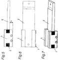
- the preload can be adjusted via the height of the rolling element in relation to the roller block.
- a height adjustment of the rolling element in a roller block, which forms the connection between the rolling element and the leaf spring, can therefore be particularly advantageous for precise adjustment.
- the use of screws for adjustment proves to be advantageous.
- roller block is attached to the leaf spring by means of a dowel with a rotational degree of freedom that allows the roller block with rolling element to pivot slightly about a vertical axis.
- Attachment to the base of the stock rail enables storage that is independent of different sleepers or sliding chair geometries. This can be achieved particularly cheaply by a clamp connection.
- a rigid clamp which is preferably formed in one piece by the clamp body, and a screw clamp, which can be screwed to the clamp body, are particularly suitable for this purpose.
- a universal use can be achieved by several receptacles in a row for the screw terminal and a corresponding toothing. During installation, the distance between the clamps can thus be adapted to the existing rail system, in particular the width of the base of the stock rail.
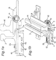
- a guide body 1 is fastened to a stock rail 3 via a clamp body 15 of a device according to the invention by means of clamps 2a, 2b.
- the guide body 1 is box-shaped in a U-shape and firmly connected to terminals 2a, 2b by means of a clamping body, a rigid terminal 2a and a screw terminal 2b being present.
- the rigid clamp 2a is arranged on the clamp body 15, to which a screw clamp 2b is screwed.
- the guide body 1 is screwed to the clamping body 15.
- a carriage 4 which in turn can be displaced and fastened in the longitudinal direction within the guide body 1.
- elongated holes 12 on a side wall of the guide body 1 for fixing the slide 4 with a screw 13.
- a rack 5 is provided on the inner wall of the guide body 1.
- Rack pieces 6 engaging in the rack 5 are arranged on the side of the slide 4.
- the relative position of the clamping body 15 to the slide 4 can thus be roughly defined by means of the connection between the clamping body 15 and the guide body 1, a fine adjustment is possible via the connection between the guide body 1 and the slide 4.
- Both the distance between the stock rail 3 and a tongue rail 11 and the tongue stroke of the tongue rail 11 differ according to the position of the storage within the switch. In the vicinity of the tongue root, the range of movement of the tongue rail 11 is small and the distance to the stock rail 3 is large.
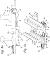
- Such a structure is in the 3a and b , such as 4a and b to see.
- 3a and b show the tongue rail 11 in a position adjacent to the stock rail 3.
- 4a and b show the tongue rail 11 in a position remote from the stock rail 3.
- the distance between the middle of the stock rail and the edge of the tongue (contact with the roller) differs depending on the type of turnout.
- FIGS Fig. 1a, b A device according to the invention in a region closer to the tip of the tongue is shown in FIGS Fig. 1a, b in the position of the stock rail 3 and 2a, b shown in the position remote from the stock rail 3.
- a leaf spring 8 is attached to the slide 4.
- the surface of the guide body facing away from the stock rail 3 is held at a distance A by the slide 4. This is dimensioned such that the leaf spring 8 does not rest on the guide body 1 even at maximum load. As a result, the effective length of the leaf spring 8 and thus the spring properties remain constant.
- Another end of the leaf spring 8 is connected to a roller body 10 via a roller block 9 and set screws 17.
- the base of the tongue rail 11 lies on this.
- the roller block 9 is connected to the leaf spring 8 by a vertical dowel pin 16. This allows a slight rotation about its axis, as a result of which the tolerances of the rolling elements 10 align at the correct angle to the contact surface of the tongue rail 11.
- set screws 17 are also arranged in the roller block, with which the rolling element 10 is adjustable in height.
- the pretensioning of the tongue rail 11 can be adapted to the requirements.
- the roughly required rolling element position is initially set via the clamping body 15 - guide body 1 connection. This can be done at the factory in the form of product variants consisting of the same parts, or at the construction site at the start of assembly.
- the entire device is clamped to the stock rail 3 via the clamps 2a, 2b.
- the slide 4 is fine-adjusted in the guide body 1, and thus also the position of the roller body 10 relative to the stock rail 3.
- the position of the slide 4 is fixed with the screw 13, through the rack 5 and the rack pieces 6 an adjustment, for example by vibration , leaning forward.
- the entire system is biased against the tongue rail 11.
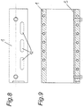
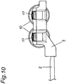
- Fig. 10 shows an alternative embodiment with two roles. This can be used, for example, when the tongue stroke is greater than the width of the foot of the tongue rail plus the roll-up path.
Landscapes
- Engineering & Computer Science (AREA)
- Mechanical Engineering (AREA)
- Architecture (AREA)
- Civil Engineering (AREA)
- Structural Engineering (AREA)
- Railway Tracks (AREA)
- Bearings For Parts Moving Linearly (AREA)
Claims (15)
- Dispositif de montage d'une lame d'aiguille (11) comportant un organe de roulement (10), un organe de guidage (1) et un ressort-lame (8) en saillie de la lame d'aiguille (11), mis en précontrainte, et sur lequel la lame d'aiguille (11) est montée de façon à coulisser par l'organe de roulement (10), le ressort-lame (8) étant logé dans l'organe de guidage (1) fixé à une contre-aiguille (3),
dispositif caractérisé en ce que
le ressort-lame (8) est réglable dans sa direction longitudinale dans l'organe de guidage (1). - Dispositif de montage selon la revendication 1,
caractérisé en ce que
le ressort-lame (8) est fixé par un chariot (4) à l'organe de guidage (1) par son extrémité opposée à celle de l'organe de roulement (10). - Dispositif de montage selon l'une des revendications 1 ou 2,
caractérisé en ce que
le chariot (4) est fixé à l'organe de guidage (1) par l'intermédiaire d'une liaison par frottement. - Dispositif de montage selon l'une des revendications 1 ou 2,
caractérisé en ce que
le chariot (4) est fixé à l'organe de guidage (1) par une liaison, une structure de surface et une contre-surface moins dure, la structure de surface régulière ou irrégulière de la surface dure s'enfonçant au cours de la fixation, dans la contre-surface moins dure. - Dispositif de montage selon l'une des revendications 1 ou 2,
caractérisé en ce que
le chariot (4) est fixé à l'organe de guidage (1) par une liaison par la forme. - Dispositif de montage selon la revendication 5,
caractérisé en ce que
la liaison par la forme est réalisée comme zone dentée sur une paroi latérale de l'organe de guidage (1) ainsi sur le chariot (4) et de préférence le vissage est également prévu sur ce côté. - Dispositif de montage selon l'une des revendications 1 à 6,
caractérisé en ce que
l'organe de serrage (15) est fixé par des éclisses (2a, 2b) au talon de la contre-aiguille (3) à état installé. - Dispositif de montage selon la revendication 7,
caractérisé en ce qu'au
moins l'une des éclisses (2a, 2b) est reliée solidairement à l'organe de serrage (15) dans différentes positions. - Dispositif de montage selon la revendication 7 ou 8,
caractérisé en ce que
l'organe de serrage (15) peut être relié solidairement à l'organe de guidage (1) dans différentes positions. - Dispositif de montage selon l'une des revendications 1 à 9,
caractérisé en ce que
l'organe de guidage (1) a une section rectangulaire. - Dispositif de montage selon l'une des revendications 1 à 10,
caractérisé en ce que
le côté du ressort-lame (8) à l'opposé de la contre-aiguille (3), est à une distance (A) de la partie d'entretoise de l'organe de guidage (1) tournée vers la contre-aiguille (3). - Dispositif de montage selon l'une des revendications 1 à 11,
caractérisé en ce que
l'organe de roulement (10) est fixé de manière réglable au ressort-lame (8) par l'intermédiaire d'un bloc à rouleaux (9), l'organe de roulement (10) étant monté de manière réglable en hauteur sur le bloc à rouleaux (9), de préférence par au moins une vis. - Dispositif de montage selon la revendication 12,
caractérisé en ce que
le bloc à rouleaux (9) est monté sur le ressort lame (8) de façon pivotante autour d'un axe montant. - Dispositif de montage selon l'une des revendications 12 à 13,
caractérisé en ce que
le bloc à rouleaux (9) comporte précisément un organe de roulement (10). - Dispositif de montage selon l'une des revendications 12 à 13,
caractérisé en ce que
le bloc à rouleaux (9) comporte deux organes de roulement (10) avec des axes de préférence parallèles.
Applications Claiming Priority (2)
| Application Number | Priority Date | Filing Date | Title |
|---|---|---|---|
| ATA51060/2016A AT519432B1 (de) | 2016-11-23 | 2016-11-23 | Vorrichtung zur lagerung einer zungenschiene |
| PCT/AT2017/060306 WO2018094434A1 (fr) | 2016-11-23 | 2017-11-21 | Dispositif pour monter une lame d'aiguille |
Publications (2)
| Publication Number | Publication Date |
|---|---|
| EP3545131A1 EP3545131A1 (fr) | 2019-10-02 |
| EP3545131B1 true EP3545131B1 (fr) | 2020-03-25 |
Family
ID=60661670
Family Applications (1)
| Application Number | Title | Priority Date | Filing Date |
|---|---|---|---|
| EP17812251.1A Active EP3545131B1 (fr) | 2016-11-23 | 2017-11-21 | Dispositif pour monter une lame d'aiguille |
Country Status (6)
| Country | Link |
|---|---|
| US (1) | US11236470B2 (fr) |
| EP (1) | EP3545131B1 (fr) |
| JP (1) | JP7005619B2 (fr) |
| KR (1) | KR20190084994A (fr) |
| AT (1) | AT519432B1 (fr) |
| WO (1) | WO2018094434A1 (fr) |
Family Cites Families (12)
| Publication number | Priority date | Publication date | Assignee | Title |
|---|---|---|---|---|
| JPS6045701U (ja) * | 1983-08-31 | 1985-03-30 | 吉原鉄道工業株式会社 | 転てつ減摩器におけるロ−ラ調整装置 |
| DE9317723U1 (de) * | 1993-11-19 | 1994-01-20 | Enzesfeld Caro Metallwerke Ag | Weiche für Gleise des schienengebundenen Verkehrs |
| AT410809B9 (de) | 1999-05-07 | 2004-01-26 | Enzesfeld Caro Metallwerke Ag | Weiche für gleise des schienengebundenen verkehrs |
| AT410331B (de) * | 1999-05-27 | 2003-03-25 | Vae Ag | Einrichtung zum erleichtern der umstellbewegung und zum elastischen verriegeln von beweglichen schienen oder schienenteilen |
| CZ200242A3 (cs) * | 1999-07-14 | 2002-05-15 | Vae Aktiengesellschaft | Zařízení k pruľnému uloľení pohyblivých částí kolejové výhybky |
| DE10110868B4 (de) * | 2001-03-07 | 2009-12-17 | Walter Hundhausen Gmbh | Rollvorrichtung |
| DE102010025770A1 (de) * | 2010-07-01 | 2012-01-05 | Schwihag Ag | Rollvorrichtung für eine Zungenschiene einer Weiche |
| KR20120066439A (ko) * | 2010-12-14 | 2012-06-22 | (주)에스아이이노텍 | 철도 분기기용 무도유 롤러 베이스 어셈블리 |
| KR101072861B1 (ko) * | 2010-12-29 | 2011-10-17 | 삼표이앤씨 주식회사 | 철도 분기기용 롤러 일체형 무도유 상판 |
| KR101254671B1 (ko) * | 2010-12-29 | 2013-04-15 | 삼표이앤씨 주식회사 | 철도 분기기용 롤러 상판 |
| GB2511046B (en) * | 2013-02-20 | 2015-02-25 | Progress Rail Services Uk Ltd | Track assembly |
| DE102014218125B3 (de) * | 2014-09-10 | 2015-12-31 | Schwihag Ag | Rollvorrichtung zum Umstellen einer Weichenzunge |
-
2016
- 2016-11-23 AT ATA51060/2016A patent/AT519432B1/de not_active IP Right Cessation
-
2017
- 2017-11-21 US US16/463,244 patent/US11236470B2/en active Active
- 2017-11-21 EP EP17812251.1A patent/EP3545131B1/fr active Active
- 2017-11-21 KR KR1020197014803A patent/KR20190084994A/ko unknown
- 2017-11-21 JP JP2019527885A patent/JP7005619B2/ja active Active
- 2017-11-21 WO PCT/AT2017/060306 patent/WO2018094434A1/fr unknown
Non-Patent Citations (1)
| Title |
|---|
| None * |
Also Published As
| Publication number | Publication date |
|---|---|
| EP3545131A1 (fr) | 2019-10-02 |
| WO2018094434A1 (fr) | 2018-05-31 |
| AT519432B1 (de) | 2019-06-15 |
| JP2019535939A (ja) | 2019-12-12 |
| US11236470B2 (en) | 2022-02-01 |
| US20200063375A1 (en) | 2020-02-27 |
| AT519432A1 (de) | 2018-06-15 |
| KR20190084994A (ko) | 2019-07-17 |
| JP7005619B2 (ja) | 2022-02-04 |
Similar Documents
| Publication | Publication Date | Title |
|---|---|---|
| AT521173B1 (de) | Biegewerkzeug mit Distanzelement | |
| EP1379791B1 (fr) | Guide lineaire | |
| EP3885518A1 (fr) | Entraînement de bras de réglage | |
| DE102006060609A1 (de) | Lineares Wälzlagerelement | |
| EP2668869B1 (fr) | Elément de verrouillage amovible | |
| EP3752694B1 (fr) | Dispositif de stationnement de voiture | |
| EP3545131B1 (fr) | Dispositif pour monter une lame d'aiguille | |
| EP3381856A1 (fr) | Ensemble de fixation comprenant un élément de fixation pour fixer un rail d'un ascenseur dans une cage d'ascenseur | |
| DE19519153C2 (de) | Führung für verstellbare Fahrzeugsitze | |
| DE2518647C3 (de) | Einfachauszug für Schubladen | |
| EP3003683B1 (fr) | Dispositif de calibrage, procédé de calibrage et procédé de production d'un dispositif de calibrage | |
| EP2126215B1 (fr) | Dispositif d'assistance au mouvement de déplacement de lames d'aiguille d'un aiguillage | |
| EP0649503B1 (fr) | Palier d'appui pour unites en mouvement a guidage lineaire | |
| EP1680977B1 (fr) | Dispositif de freinage pour un élément de meuble mobile | |
| EP1627954A2 (fr) | Dispositif de fixation d'une contre-aiguille sur le côté interne par rapport à la voie d'un dispositif d'aiguille d'un aiguillage | |
| WO2016198339A1 (fr) | Dispositif de fixation pour rails | |
| EP4174268B1 (fr) | Ferrure roulante de porte coulissante et agencement de porte coulissante associé | |
| AT519530B1 (de) | Vorrichtung zum bewegen einer zungenschiene einer weiche | |
| DE2133202A1 (de) | Nachstellvorrichtung fuer das lueftspiel einer durch federkraft einrueckbaren und elektromagnetisch geluefteten bremse | |
| EP4148219B1 (fr) | Dispositif pour le montage réglable d'un actionneur linéaire sur une structure supérieure | |
| AT517271B1 (de) | Bremseinheit für einen Gleisprellbock | |
| DE102015010990A1 (de) | Aufhänge- oder Abstützvorrichtung für sich in vertikaler Richtung verschiebende Lasten, insbesondere Rohrleitungen und dergleichen | |
| CH696416A5 (de) | Laufschieneneinrichtung für eine Schublade. | |
| WO2019121096A1 (fr) | Support d'appareil de mesure pour la mesure d'un rail déplacé | |
| WO2001014200A1 (fr) | Systeme de verrouillage d'extremite d'aiguillage |
Legal Events
| Date | Code | Title | Description |
|---|---|---|---|
| STAA | Information on the status of an ep patent application or granted ep patent |
Free format text: STATUS: UNKNOWN |
|
| STAA | Information on the status of an ep patent application or granted ep patent |
Free format text: STATUS: THE INTERNATIONAL PUBLICATION HAS BEEN MADE |
|
| PUAI | Public reference made under article 153(3) epc to a published international application that has entered the european phase |
Free format text: ORIGINAL CODE: 0009012 |
|
| STAA | Information on the status of an ep patent application or granted ep patent |
Free format text: STATUS: REQUEST FOR EXAMINATION WAS MADE |
|
| 17P | Request for examination filed |
Effective date: 20190429 |
|
| AK | Designated contracting states |
Kind code of ref document: A1 Designated state(s): AL AT BE BG CH CY CZ DE DK EE ES FI FR GB GR HR HU IE IS IT LI LT LU LV MC MK MT NL NO PL PT RO RS SE SI SK SM TR |
|
| AX | Request for extension of the european patent |
Extension state: BA ME |
|
| GRAP | Despatch of communication of intention to grant a patent |
Free format text: ORIGINAL CODE: EPIDOSNIGR1 |
|
| STAA | Information on the status of an ep patent application or granted ep patent |
Free format text: STATUS: GRANT OF PATENT IS INTENDED |
|
| DAV | Request for validation of the european patent (deleted) | ||
| DAX | Request for extension of the european patent (deleted) | ||
| INTG | Intention to grant announced |
Effective date: 20191126 |
|
| GRAS | Grant fee paid |
Free format text: ORIGINAL CODE: EPIDOSNIGR3 |
|
| GRAA | (expected) grant |
Free format text: ORIGINAL CODE: 0009210 |
|
| STAA | Information on the status of an ep patent application or granted ep patent |
Free format text: STATUS: THE PATENT HAS BEEN GRANTED |
|
| AK | Designated contracting states |
Kind code of ref document: B1 Designated state(s): AL AT BE BG CH CY CZ DE DK EE ES FI FR GB GR HR HU IE IS IT LI LT LU LV MC MK MT NL NO PL PT RO RS SE SI SK SM TR |
|
| REG | Reference to a national code |
Ref country code: GB Ref legal event code: FG4D Free format text: NOT ENGLISH |
|
| REG | Reference to a national code |
Ref country code: DE Ref legal event code: R096 Ref document number: 502017004410 Country of ref document: DE |
|
| REG | Reference to a national code |
Ref country code: AT Ref legal event code: REF Ref document number: 1248695 Country of ref document: AT Kind code of ref document: T Effective date: 20200415 Ref country code: IE Ref legal event code: FG4D Free format text: LANGUAGE OF EP DOCUMENT: GERMAN |
|
| PG25 | Lapsed in a contracting state [announced via postgrant information from national office to epo] |
Ref country code: FI Free format text: LAPSE BECAUSE OF FAILURE TO SUBMIT A TRANSLATION OF THE DESCRIPTION OR TO PAY THE FEE WITHIN THE PRESCRIBED TIME-LIMIT Effective date: 20200325 Ref country code: NO Free format text: LAPSE BECAUSE OF FAILURE TO SUBMIT A TRANSLATION OF THE DESCRIPTION OR TO PAY THE FEE WITHIN THE PRESCRIBED TIME-LIMIT Effective date: 20200625 Ref country code: RS Free format text: LAPSE BECAUSE OF FAILURE TO SUBMIT A TRANSLATION OF THE DESCRIPTION OR TO PAY THE FEE WITHIN THE PRESCRIBED TIME-LIMIT Effective date: 20200325 |
|
| PG25 | Lapsed in a contracting state [announced via postgrant information from national office to epo] |
Ref country code: BG Free format text: LAPSE BECAUSE OF FAILURE TO SUBMIT A TRANSLATION OF THE DESCRIPTION OR TO PAY THE FEE WITHIN THE PRESCRIBED TIME-LIMIT Effective date: 20200625 Ref country code: GR Free format text: LAPSE BECAUSE OF FAILURE TO SUBMIT A TRANSLATION OF THE DESCRIPTION OR TO PAY THE FEE WITHIN THE PRESCRIBED TIME-LIMIT Effective date: 20200626 Ref country code: SE Free format text: LAPSE BECAUSE OF FAILURE TO SUBMIT A TRANSLATION OF THE DESCRIPTION OR TO PAY THE FEE WITHIN THE PRESCRIBED TIME-LIMIT Effective date: 20200325 Ref country code: LV Free format text: LAPSE BECAUSE OF FAILURE TO SUBMIT A TRANSLATION OF THE DESCRIPTION OR TO PAY THE FEE WITHIN THE PRESCRIBED TIME-LIMIT Effective date: 20200325 Ref country code: HR Free format text: LAPSE BECAUSE OF FAILURE TO SUBMIT A TRANSLATION OF THE DESCRIPTION OR TO PAY THE FEE WITHIN THE PRESCRIBED TIME-LIMIT Effective date: 20200325 |
|
| REG | Reference to a national code |
Ref country code: NL Ref legal event code: MP Effective date: 20200325 |
|
| REG | Reference to a national code |
Ref country code: LT Ref legal event code: MG4D |
|
| PG25 | Lapsed in a contracting state [announced via postgrant information from national office to epo] |
Ref country code: NL Free format text: LAPSE BECAUSE OF FAILURE TO SUBMIT A TRANSLATION OF THE DESCRIPTION OR TO PAY THE FEE WITHIN THE PRESCRIBED TIME-LIMIT Effective date: 20200325 |
|
| PG25 | Lapsed in a contracting state [announced via postgrant information from national office to epo] |
Ref country code: PT Free format text: LAPSE BECAUSE OF FAILURE TO SUBMIT A TRANSLATION OF THE DESCRIPTION OR TO PAY THE FEE WITHIN THE PRESCRIBED TIME-LIMIT Effective date: 20200818 Ref country code: LT Free format text: LAPSE BECAUSE OF FAILURE TO SUBMIT A TRANSLATION OF THE DESCRIPTION OR TO PAY THE FEE WITHIN THE PRESCRIBED TIME-LIMIT Effective date: 20200325 Ref country code: CZ Free format text: LAPSE BECAUSE OF FAILURE TO SUBMIT A TRANSLATION OF THE DESCRIPTION OR TO PAY THE FEE WITHIN THE PRESCRIBED TIME-LIMIT Effective date: 20200325 Ref country code: IS Free format text: LAPSE BECAUSE OF FAILURE TO SUBMIT A TRANSLATION OF THE DESCRIPTION OR TO PAY THE FEE WITHIN THE PRESCRIBED TIME-LIMIT Effective date: 20200725 Ref country code: SK Free format text: LAPSE BECAUSE OF FAILURE TO SUBMIT A TRANSLATION OF THE DESCRIPTION OR TO PAY THE FEE WITHIN THE PRESCRIBED TIME-LIMIT Effective date: 20200325 Ref country code: RO Free format text: LAPSE BECAUSE OF FAILURE TO SUBMIT A TRANSLATION OF THE DESCRIPTION OR TO PAY THE FEE WITHIN THE PRESCRIBED TIME-LIMIT Effective date: 20200325 Ref country code: EE Free format text: LAPSE BECAUSE OF FAILURE TO SUBMIT A TRANSLATION OF THE DESCRIPTION OR TO PAY THE FEE WITHIN THE PRESCRIBED TIME-LIMIT Effective date: 20200325 Ref country code: SM Free format text: LAPSE BECAUSE OF FAILURE TO SUBMIT A TRANSLATION OF THE DESCRIPTION OR TO PAY THE FEE WITHIN THE PRESCRIBED TIME-LIMIT Effective date: 20200325 |
|
| REG | Reference to a national code |
Ref country code: DE Ref legal event code: R097 Ref document number: 502017004410 Country of ref document: DE |
|
| PG25 | Lapsed in a contracting state [announced via postgrant information from national office to epo] |
Ref country code: IT Free format text: LAPSE BECAUSE OF FAILURE TO SUBMIT A TRANSLATION OF THE DESCRIPTION OR TO PAY THE FEE WITHIN THE PRESCRIBED TIME-LIMIT Effective date: 20200325 Ref country code: DK Free format text: LAPSE BECAUSE OF FAILURE TO SUBMIT A TRANSLATION OF THE DESCRIPTION OR TO PAY THE FEE WITHIN THE PRESCRIBED TIME-LIMIT Effective date: 20200325 Ref country code: ES Free format text: LAPSE BECAUSE OF FAILURE TO SUBMIT A TRANSLATION OF THE DESCRIPTION OR TO PAY THE FEE WITHIN THE PRESCRIBED TIME-LIMIT Effective date: 20200325 |
|
| PLBE | No opposition filed within time limit |
Free format text: ORIGINAL CODE: 0009261 |
|
| STAA | Information on the status of an ep patent application or granted ep patent |
Free format text: STATUS: NO OPPOSITION FILED WITHIN TIME LIMIT |
|
| PG25 | Lapsed in a contracting state [announced via postgrant information from national office to epo] |
Ref country code: PL Free format text: LAPSE BECAUSE OF FAILURE TO SUBMIT A TRANSLATION OF THE DESCRIPTION OR TO PAY THE FEE WITHIN THE PRESCRIBED TIME-LIMIT Effective date: 20200325 |
|
| 26N | No opposition filed |
Effective date: 20210112 |
|
| PG25 | Lapsed in a contracting state [announced via postgrant information from national office to epo] |
Ref country code: MC Free format text: LAPSE BECAUSE OF FAILURE TO SUBMIT A TRANSLATION OF THE DESCRIPTION OR TO PAY THE FEE WITHIN THE PRESCRIBED TIME-LIMIT Effective date: 20200325 |
|
| REG | Reference to a national code |
Ref country code: CH Ref legal event code: PL |
|
| PG25 | Lapsed in a contracting state [announced via postgrant information from national office to epo] |
Ref country code: LU Free format text: LAPSE BECAUSE OF NON-PAYMENT OF DUE FEES Effective date: 20201121 |
|
| REG | Reference to a national code |
Ref country code: BE Ref legal event code: MM Effective date: 20201130 |
|
| PG25 | Lapsed in a contracting state [announced via postgrant information from national office to epo] |
Ref country code: LI Free format text: LAPSE BECAUSE OF NON-PAYMENT OF DUE FEES Effective date: 20201130 Ref country code: CH Free format text: LAPSE BECAUSE OF NON-PAYMENT OF DUE FEES Effective date: 20201130 |
|
| PG25 | Lapsed in a contracting state [announced via postgrant information from national office to epo] |
Ref country code: FR Free format text: LAPSE BECAUSE OF NON-PAYMENT OF DUE FEES Effective date: 20201130 Ref country code: IE Free format text: LAPSE BECAUSE OF NON-PAYMENT OF DUE FEES Effective date: 20201121 |
|
| PG25 | Lapsed in a contracting state [announced via postgrant information from national office to epo] |
Ref country code: TR Free format text: LAPSE BECAUSE OF FAILURE TO SUBMIT A TRANSLATION OF THE DESCRIPTION OR TO PAY THE FEE WITHIN THE PRESCRIBED TIME-LIMIT Effective date: 20200325 Ref country code: MT Free format text: LAPSE BECAUSE OF FAILURE TO SUBMIT A TRANSLATION OF THE DESCRIPTION OR TO PAY THE FEE WITHIN THE PRESCRIBED TIME-LIMIT Effective date: 20200325 Ref country code: CY Free format text: LAPSE BECAUSE OF FAILURE TO SUBMIT A TRANSLATION OF THE DESCRIPTION OR TO PAY THE FEE WITHIN THE PRESCRIBED TIME-LIMIT Effective date: 20200325 |
|
| PG25 | Lapsed in a contracting state [announced via postgrant information from national office to epo] |
Ref country code: MK Free format text: LAPSE BECAUSE OF FAILURE TO SUBMIT A TRANSLATION OF THE DESCRIPTION OR TO PAY THE FEE WITHIN THE PRESCRIBED TIME-LIMIT Effective date: 20200325 Ref country code: AL Free format text: LAPSE BECAUSE OF FAILURE TO SUBMIT A TRANSLATION OF THE DESCRIPTION OR TO PAY THE FEE WITHIN THE PRESCRIBED TIME-LIMIT Effective date: 20200325 |
|
| GBPC | Gb: european patent ceased through non-payment of renewal fee |
Effective date: 20211121 |
|
| PG25 | Lapsed in a contracting state [announced via postgrant information from national office to epo] |
Ref country code: BE Free format text: LAPSE BECAUSE OF NON-PAYMENT OF DUE FEES Effective date: 20201130 |
|
| PG25 | Lapsed in a contracting state [announced via postgrant information from national office to epo] |
Ref country code: GB Free format text: LAPSE BECAUSE OF NON-PAYMENT OF DUE FEES Effective date: 20211121 |
|
| P01 | Opt-out of the competence of the unified patent court (upc) registered |
Effective date: 20230503 |
|
| PG25 | Lapsed in a contracting state [announced via postgrant information from national office to epo] |
Ref country code: SI Free format text: LAPSE BECAUSE OF FAILURE TO SUBMIT A TRANSLATION OF THE DESCRIPTION OR TO PAY THE FEE WITHIN THE PRESCRIBED TIME-LIMIT Effective date: 20200325 |
|
| PGFP | Annual fee paid to national office [announced via postgrant information from national office to epo] |
Ref country code: DE Payment date: 20231127 Year of fee payment: 7 Ref country code: AT Payment date: 20231129 Year of fee payment: 7 |