EP1680977B1 - Dispositif de freinage pour un élément de meuble mobile - Google Patents
Dispositif de freinage pour un élément de meuble mobile Download PDFInfo
- Publication number
- EP1680977B1 EP1680977B1 EP05024610A EP05024610A EP1680977B1 EP 1680977 B1 EP1680977 B1 EP 1680977B1 EP 05024610 A EP05024610 A EP 05024610A EP 05024610 A EP05024610 A EP 05024610A EP 1680977 B1 EP1680977 B1 EP 1680977B1
- Authority
- EP
- European Patent Office
- Prior art keywords
- braking device
- braking
- brake
- brake blocks
- movable component
- Prior art date
- Legal status (The legal status is an assumption and is not a legal conclusion. Google has not performed a legal analysis and makes no representation as to the accuracy of the status listed.)
- Active
Links
- 230000015572 biosynthetic process Effects 0.000 claims description 5
- 238000005755 formation reaction Methods 0.000 claims description 5
- 125000006850 spacer group Chemical group 0.000 claims description 5
- 239000012815 thermoplastic material Substances 0.000 claims description 5
- 229910052751 metal Inorganic materials 0.000 claims description 4
- 239000002184 metal Substances 0.000 claims description 4
- 239000004033 plastic Substances 0.000 claims description 4
- 229920003023 plastic Polymers 0.000 claims description 4
- 229910000831 Steel Inorganic materials 0.000 claims description 2
- 229910052782 aluminium Inorganic materials 0.000 claims description 2
- XAGFODPZIPBFFR-UHFFFAOYSA-N aluminium Chemical compound [Al] XAGFODPZIPBFFR-UHFFFAOYSA-N 0.000 claims description 2
- 239000011248 coating agent Substances 0.000 claims description 2
- 238000000576 coating method Methods 0.000 claims description 2
- 239000010959 steel Substances 0.000 claims description 2
- 241000446313 Lamella Species 0.000 claims 1
- 239000004411 aluminium Substances 0.000 claims 1
- 230000000694 effects Effects 0.000 description 4
- 230000003068 static effect Effects 0.000 description 4
- 238000013461 design Methods 0.000 description 3
- 238000010276 construction Methods 0.000 description 2
- 239000003365 glass fiber Substances 0.000 description 2
- 238000003780 insertion Methods 0.000 description 2
- 230000037431 insertion Effects 0.000 description 2
- 239000000314 lubricant Substances 0.000 description 2
- 239000000725 suspension Substances 0.000 description 2
- 229920001169 thermoplastic Polymers 0.000 description 2
- 239000004416 thermosoftening plastic Substances 0.000 description 2
- 229920002430 Fibre-reinforced plastic Polymers 0.000 description 1
- 229920006883 PAMXD6 Polymers 0.000 description 1
- 239000004952 Polyamide Substances 0.000 description 1
- 150000001875 compounds Chemical class 0.000 description 1
- 230000006835 compression Effects 0.000 description 1
- 238000007906 compression Methods 0.000 description 1
- 230000001419 dependent effect Effects 0.000 description 1
- 238000011161 development Methods 0.000 description 1
- 230000018109 developmental process Effects 0.000 description 1
- 238000006073 displacement reaction Methods 0.000 description 1
- 239000011151 fibre-reinforced plastic Substances 0.000 description 1
- 239000000463 material Substances 0.000 description 1
- 230000013011 mating Effects 0.000 description 1
- 239000000203 mixture Substances 0.000 description 1
- 239000006223 plastic coating Substances 0.000 description 1
- 229920002647 polyamide Polymers 0.000 description 1
- 238000005096 rolling process Methods 0.000 description 1
- 238000000926 separation method Methods 0.000 description 1
- 239000007787 solid Substances 0.000 description 1
- 239000007858 starting material Substances 0.000 description 1
- 230000001360 synchronised effect Effects 0.000 description 1
- 238000012549 training Methods 0.000 description 1
- 238000012546 transfer Methods 0.000 description 1
- 230000007704 transition Effects 0.000 description 1
Images

Classifications
-
- A—HUMAN NECESSITIES
- A47—FURNITURE; DOMESTIC ARTICLES OR APPLIANCES; COFFEE MILLS; SPICE MILLS; SUCTION CLEANERS IN GENERAL
- A47C—CHAIRS; SOFAS; BEDS
- A47C1/00—Chairs adapted for special purposes
- A47C1/02—Reclining or easy chairs
- A47C1/031—Reclining or easy chairs having coupled concurrently adjustable supporting parts
- A47C1/032—Reclining or easy chairs having coupled concurrently adjustable supporting parts the parts being movably-coupled seat and back-rest
- A47C1/03294—Reclining or easy chairs having coupled concurrently adjustable supporting parts the parts being movably-coupled seat and back-rest slidingly movable in the base frame, e.g. by rollers
-
- A—HUMAN NECESSITIES
- A47—FURNITURE; DOMESTIC ARTICLES OR APPLIANCES; COFFEE MILLS; SPICE MILLS; SUCTION CLEANERS IN GENERAL
- A47C—CHAIRS; SOFAS; BEDS
- A47C1/00—Chairs adapted for special purposes
- A47C1/02—Reclining or easy chairs
- A47C1/031—Reclining or easy chairs having coupled concurrently adjustable supporting parts
- A47C1/032—Reclining or easy chairs having coupled concurrently adjustable supporting parts the parts being movably-coupled seat and back-rest
- A47C1/03205—Reclining or easy chairs having coupled concurrently adjustable supporting parts the parts being movably-coupled seat and back-rest having adjustable and lockable inclination
- A47C1/0325—Reclining or easy chairs having coupled concurrently adjustable supporting parts the parts being movably-coupled seat and back-rest having adjustable and lockable inclination by means of clamps or friction locking members
Definitions
- the invention relates to a braking device for a movable component of a furniture element, in particular a upholstered furniture element, with the features of the preamble of claim 1 and a furniture element with such a braking device according to claim 9.
- a furniture element on which a braking device of the type in question can be realized in particular a upholstered furniture element, namely a upholstered chair.
- a furniture element is known in various embodiments ( WO 95/25452 A1 ).
- a coupled backrest and seat adjustment is characteristic.
- This backrest and seat adjustment realized with a connection mechanism between the support frame, the backrest and the seat a synchronous adjustment of the backrest and seat from a highest, upright position, the sitting position, in a lowest, preferably extended position, the lying position.
- the seat When moving from the sitting position to the lying position, the seat performs a slight movement, which has a significant translational component - a displacement component.
- a braking device between the seat and support frame is arranged, one on the movable member (or on the support frame) mounted, usually made of metal slide rail and one of these associated brake bearing block on the opposite component, So on the support frame (or on the moving component) has.
- the teaching is therefore based on the problem of optimizing a braking device of the type described above with braking surfaces and brake shoes in the direction of a low start truck and good adjustability.
- the support carrying the movable component on the support frame is separated from the actual brake bearing block.
- the support function on the one hand and the brake function on the other hand are separated.
- the upper braking surface of the slide remains largely free of force resulting from the loading of the movable member and its suspension on the support frame.
- the normal force on the affected braking surface is usually relatively low.
- the braking force on the braking surfaces is thus actually only or predominantly generated by the employment of the brake shoes to the braking surfaces and is accordingly sensitively adjustable. It has been shown that thus optimizes the adjustability and the starter truck can be significantly reduced, although one remains in the well-known design solution with braking surfaces and brake shoes.
- the subject of the invention is also a furniture element with a corresponding braking device according to the invention.
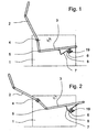
- the braking device shown in the drawing is intended and suitable for a movable component of a furniture element, in particular for a movable component of a seating furniture element, and in particular, as shown here, for the movable seat of a upholstered furniture element, realized in which a coupledstrong- and seat adjustment is.
- FIG. 1 and 2 illustrated embodiment shows first on the support frame 1 of the running here as upholstered seat furniture element a backrest 2 and a seat 3.
- the backrest 2 is pivotally mounted on the support frame 1 to a pivot bearing 4.
- the backrest 2 is pivotally connected to the seat 3 at an angle via a pivot joint 5.
- a cross-beam 6, which carries the seat 3 there.
- located at the front edge of the seat 3 in the region of the crossbeam 6 on each side of the support frame 1 each have a slide 7. In the illustration, however, is due to the Direction of the view shown only a slide 7 to see.
- the seat 3 represents a movable component of a furniture element, here just a upholstered chair.
- a brake bearing block 8 is mounted on the support frame 1, on the cross-beam 6, .
- the brake bearing block 8 forms a sliding guide for the Sliding rail 7.
- the slide 7 thus slides in the transition from the sitting position in the lying position in the brake bearing block 8 with a predetermined sliding friction.
- the movable component of the furniture element here so the seat 3 of the upholstered chair, can be adjusted against a presettable force effect and fix with appropriate design of the braking device from slide 7 and brake pad block 8 in certain positions or lock.
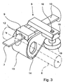
- Fig. 3 shows an overall view of the actual braking device according to the invention
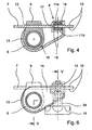
- Fig. 4 shows a longitudinal section through slide rail 7 and brake pad block 8
- Fig. 5 one at right angles to the section of Fig. 4 lying cross section in the region of the brake bearing block 8 shows.
- the braking device according to the invention can be explained in detail.
- the brake bearing block 8 on the one hand, the movable member 3 on the support frame 1, sliding on the slide 7 freely sliding bracket 9, on the other on opposite braking surfaces 10 of the slide 7 coming to rest, pressed against the braking surfaces 10 flat
- the holder 9 is spatially separated from the brake shoes 11, here realized by the holder 9 and the brake shoes 11 being arranged one behind the other in the longitudinal direction of the slide rail 7. This is not mandatory, the arrangement could also be next to each other, if you had a double rail. A single slide 7 is more practical.
- the drawing shows that the brake shoes 11 by means of a clamping means 19, preferably designed as a clamping screw with a well-grip operating knob on the braking surfaces 10 are adjustable.
- the braking force on the braking surfaces 10 of the slide rail 7 is generated by the hiring of the brake shoes 11 to the braking surfaces 10 by means of the clamping means 19 in any case quite predominantly. Static friction of weight thus plays a smaller role in this division than in the prior art.
- a clamping screw as a clamping means 19, one can also provide other means, such as an eccentric lever or a clamping knob. It is essential that the clamping means 19 the As desired setting the brake shoes 11 to the braking surfaces 10, so the compression and holding together of the brake shoes 11 against the braking surfaces 10 makes.
- the slide rail 7 is guided by a recess 12 in the holder 9, which is designed as a compact component, in particular as a component made of reinforced thermoplastic material. It can be seen in the holder 9, the cross-member 6 used there of the support frame 1 in section. On the underside of the movable member 3, so the upholstered furniture of the seat, a slide rail 7 is normally arranged right and left respectively. Accordingly, in each case a holder 9 is arranged on the right and left.
- the braking device according to the invention must be present only on one side, which is sufficient in most cases for effective braking.
- Fig. 4 and 5 show now in the context that here the brake shoes 11, ie an upper brake shoe 11a and a lower brake shoe 11b, are arranged in a receiving housing 13.
- the brake shoe 11a is located above the slide rail 7, the brake shoe 11b below the slide rail 7.
- Each brake shoe 11 is located on a flat side of the slide rail 7, the two flat sides form the braking surfaces 10th
- the plastic provided may be, for example, a polyamide with glass fiber content, for example a polyarylamide PAMXD6 with 60% glass fiber content. This can be sprayed relatively hard with a smooth surface and leads technically and visually to a perfect result.
- a polyamide with glass fiber content for example a polyarylamide PAMXD6 with 60% glass fiber content.
- This can be sprayed relatively hard with a smooth surface and leads technically and visually to a perfect result.
- other compositions are known from the prior art.
- one can produce the receiving housing 13 and / or the housing cover 14 and the holder 9 also made of metal, possibly with a plastic coating.
- Figure 6 shows an end view of the side in the area in which the housing cover 14 is connected to the receiving housing 13.
- This compound is characterized in the illustrated and preferred embodiment, characterized in that the receiving housing 13 and the housing cover 14 are provided with mating form-fitting formations 15 which are in engagement with the housing cover 14 with each other.
- the positive locking formations 15 are here tongue and groove training, which can also be designed as a dovetail formations.
- the form-locking formations 15 may extend over the full length or only over part of the length of the corresponding section.
- the teaching is based on the fact that the holder 9 for suspending the movable component 3 on the support frame 1 on the one hand from the brake bearing block 8 on the other hand is separated.
- the illustrated and preferred embodiment shows a way how you can physically perform this separation, not only spatially, but still achieved in the assembled state again a physical connection.
- the receiving housing 13 additionally has a space 16 for the holder 9 and the holder 9 is coupled to the brake shoes 11 by the arrangement in the space 16 of the receiving housing 13.
- the brake shoes 11 are designed as elongated, transversely over the braking surfaces 10 of the slide rail 7 extending plates. You can see that especially well in Fig. 5 ,
- the brake shoes 11 in the form of the elongated plates as such consist of a material and are treated on the surfaces so that a direct contact with the braking surfaces 10 is possible.
- this could then be provided if the brake shoes 11 as such consist of a fiber-reinforced plastic, optionally additionally mixed with a lubricant, in particular a thermoplastic.
- a lubricant in particular a thermoplastic.
- the illustrated and preferred embodiment of the braking device is structurally a particularly simple structure that ensures a quick assembly.
- the elongated plates forming the brake shoes 11 are mounted at one end in the receiving housing 13 in a plug-in bearing 18. Further, it is provided that the brake shoes 11 forming elongated plates at the other end by means of the clamping means, here the clamping screw 19, are compressible.
- the brake shoes 11 a, 11 b and the elongated plates forming these brake shoes 11 can simply be inserted in the longitudinal direction into the receiving housing 13 and there into the end-side plug-in bearing 18. You have already experienced a prefix in the receiving housing 13.
- the clamping means 19, so here the clamping screw 19, a spacer sleeve 22 is assigned between the brake shoes 11.
- the spacer sleeve 22 may also consist of fiber-reinforced thermoplastic material. It has such a thickness that it defines the minimum distance of the brake shoes 11a, 11b from each other, so that over-tightening of the brake device is reliably avoided.
- the thickness of the spacer sleeve 22 is adapted to the thickness of the slide rail 7, so the distance of the braking surfaces 10 of the slide rail 7 from each other.
- annular groove 23 Indicated on the clamping screw 19 of the illustrated and preferred embodiment is still an annular groove 23. This serves to a transverse pin, which is inserted at the appropriate location in the housing cover 14, record. This in Fig. 5 Without reference numerals indicated transverse pin allows an adjustment of the clamping screw 19 between the edges of the annular groove 23, but prevents accidental unscrewing of the clamping screw 19 from the thread 20a.
- the illustrated and preferred embodiment finally shows a structurally particularly expedient solution such that the housing cover 14 has a jack 24 for the clamping screw 19, in this case such that the housing cover 14 is captively connected to the receiving housing 13 with inserted clamping screw 19.
- the assembly can be seen in Fig. 3 ,
- the jack 24 may also be arranged in the receiving housing 13, which depends on the specific construction.
Claims (9)
- Dispositif de freinage pour un composant mobile d'un élément de meuble, notamment d'un élément de meuble rembourré, qui présente un bâti porteur (1),
avec au moins un rail de glissement (7) à monter sur le composant mobile (3) ou sur le bâti porteur (1) et
avec au moins un bloc palier de freinage (8) à monter sur le bâti porteur (1) ou sur le composant mobile (3),
le bloc palier de freinage (8) présentant une fixation (9) portant le composant mobile (3) sur le bâti porteur (1), pouvant glisser librement sur le rail de glissement (7), ainsi que des mâchoires de frein plates (11) venant en appui contre des faces de freinage (10) en regard l'une de l'autre du rail de glissement (7),
caractérisé en ce que
la fixation (9) est séparée spatialement des mâchoires de frein (11),
les mâchoires de frein (11) peuvent être appliquées au moyen d'un moyen de serrage (19), notamment une vis de serrage, contre les faces de freinage (10), et
la force de freinage contre les faces de freinage (10) du rail de glissement (7) n'est produite que par ou principalement par l'application des mâchoires de frein (11) contre les faces de freinage (10) au moyen du moyen de serrage (19). - Dispositif de freinage selon la revendication 1, caractérisé en ce que la fixation (9) et les mâchoires de frein (11) sont disposées les unes derrière les autres dans la direction longitudinale du rail de glissement (7).
- Dispositif de freinage selon la revendication 1 ou 2, caractérisé en ce que la fixation (9) est réalisée sous forme de composant compact (3), en particulier en plastique thermoplastique renforcé.
- Dispositif de freinage selon l'une quelconque des revendications 1 à 3, caractérisé en ce que les mâchoires de frein (11) sont disposées dans un boîtier de réception (13), le boîtier de réception (13) présentant de préférence un couvercle de boîtier amovible (14) et/ou, de préférence, le boîtier de réception (13) et/ou le couvercle de boîtier (14) étant réalisés à partir d'un plastique thermoplastique renforcé, et/ou de préférence, le boîtier de réception (13) et le couvercle de boîtier (14) étant pourvus de formations d'engagement par coopération géométrique adaptées l'une à l'autre (15), qui sont en prise mutuellement lorsque le couvercle de boîtier (14) est posé, et/ou, de préférence, le boîtier de réception (13) présentant en outre un espace (16) pour la fixation (9) et la fixation (9) étant accouplée aux mâchoires de frein (11) par l'agencement dans l'espace (16) du boîtier de réception (13).
- Dispositif de freinage selon l'une quelconque des revendications 1 à 4, caractérisé en ce que les mâchoires de frein (11) sont réalisées sous forme de plaques allongées, s'étendant transversalement sur les faces de freinage (10) du rail de glissement (7),
les plaques allongées formant les mâchoires de frein (11) étant de préférence réalisées en métal, notamment en acier traité en surface ou en aluminium, et éventuellement là où elles viennent en appui contre les faces de freinage (10) du rail de glissement (7), étant pourvues d'un support glissant (17), notamment sous forme de revêtement ou de plaquette glissante en plastique. - Dispositif de freinage selon la revendication 5, caractérisé en ce que les plaques allongées formant les mâchoires de frein (11) sont montées à une extrémité dans le boîtier de réception (13) dans un palier enfichable (18), les plaques allongées formant les mâchoires de frein (11) pouvant de préférence être comprimées à l'autre extrémité au moyen du moyen de serrage (19).
- Dispositif de freinage selon l'une quelconque des revendications 1 à 6, caractérisé en ce que l'on associe au moyen de serrage (19) une douille d'espacement (22) entre les mâchoires de frein (11).
- Dispositif de freinage selon l'une quelconque des revendications 1 à 7, caractérisé en ce que le boîtier de réception (13), ou, s'il est présent, le couvercle de boîtier (14), présente une douille enfichable (24) pour le moyen de serrage (19), de préférence de telle sorte que le couvercle de boîtier (14) soit connecté de manière imperdable au boîtier de réception (13) lorsque le moyen de serrage (19) est monté.
- Elément de meuble, en particulier élément de meuble rembourré, comprenant un bâti porteur (1) et un composant (3) déplaçable monté mobile sur le bâti porteur (1), notamment un siège de l'élément de meuble rembourré, ainsi qu'un dispositif de freinage pour le composant mobile (3), qui présente au moins un bloc palier de freinage (8) à monter sur le bâti porteur (1) (ou sur le composant mobile (3)),
caractérisé par
un dispositif de freinage selon l'une quelconque des revendications 1 à 8, sur au moins un côté, de préférence sur exactement un côté du composant mobile (3) (ou du bâti porteur (1)).
Priority Applications (1)
| Application Number | Priority Date | Filing Date | Title |
|---|---|---|---|
| PL05024610T PL1680977T3 (pl) | 2005-01-12 | 2005-11-11 | Urządzenie hamulcowe dla ruchomej części elementu mebla |
Applications Claiming Priority (1)
| Application Number | Priority Date | Filing Date | Title |
|---|---|---|---|
| DE200520000463 DE202005000463U1 (de) | 2005-01-12 | 2005-01-12 | Bremseinrichtung für ein bewegliches Bauteil eines Möbelelements |
Publications (3)
| Publication Number | Publication Date |
|---|---|
| EP1680977A2 EP1680977A2 (fr) | 2006-07-19 |
| EP1680977A3 EP1680977A3 (fr) | 2008-04-23 |
| EP1680977B1 true EP1680977B1 (fr) | 2010-05-19 |
Family
ID=34353868
Family Applications (1)
| Application Number | Title | Priority Date | Filing Date |
|---|---|---|---|
| EP05024610A Active EP1680977B1 (fr) | 2005-01-12 | 2005-11-11 | Dispositif de freinage pour un élément de meuble mobile |
Country Status (4)
| Country | Link |
|---|---|
| EP (1) | EP1680977B1 (fr) |
| AT (1) | ATE468048T1 (fr) |
| DE (2) | DE202005000463U1 (fr) |
| PL (1) | PL1680977T3 (fr) |
Families Citing this family (2)
| Publication number | Priority date | Publication date | Assignee | Title |
|---|---|---|---|---|
| DE202013002163U1 (de) | 2013-03-07 | 2013-04-22 | Erpo Möbelwerk GmbH | Sitzmöbel mit Sitz- und Fußteil |
| DE202014010096U1 (de) | 2014-12-23 | 2015-02-06 | Erpo Möbelwerk GmbH | Sitzmöbel mit verstellbarer Beinauflage |
Family Cites Families (7)
| Publication number | Priority date | Publication date | Assignee | Title |
|---|---|---|---|---|
| DE7302544U (de) | 1973-05-03 | Lusch F | Verstellbarer Liegestuhl | |
| IT8521436V0 (it) | 1985-04-12 | 1985-04-12 | Salotti Natuzzi Srl | Poltrona a schienale reclinabile. |
| FI72865C (fi) * | 1985-11-22 | 1987-08-10 | Jorma Saarainen | Anordning foer reglering och laosning av ryggstoed pao sits. |
| DE8534420U1 (de) | 1985-12-06 | 1986-02-06 | Pfalzberger, Heinrich, Basel | Verstellbares Sitzmöbel |
| DK9400143U3 (da) | 1994-03-18 | 1994-07-22 | P Schultz & Co As | Beslag til synkron regulering af sæde og ryg i stole |
| DE19638075C1 (de) | 1996-08-29 | 1998-02-26 | Jungjohann Thomas | Bremseinrichtung für ein bewegliches Bauteil eines Möbelelementes, insbesondere Polstermöbelelementes |
| DE29919528U1 (de) * | 1999-11-06 | 2000-01-27 | Steltemeier Josef Gmbh | Sitzmöbel |
-
2005
- 2005-01-12 DE DE200520000463 patent/DE202005000463U1/de not_active Expired - Lifetime
- 2005-11-11 AT AT05024610T patent/ATE468048T1/de active
- 2005-11-11 DE DE502005009593T patent/DE502005009593D1/de active Active
- 2005-11-11 PL PL05024610T patent/PL1680977T3/pl unknown
- 2005-11-11 EP EP05024610A patent/EP1680977B1/fr active Active
Also Published As
| Publication number | Publication date |
|---|---|
| PL1680977T3 (pl) | 2010-08-31 |
| EP1680977A3 (fr) | 2008-04-23 |
| ATE468048T1 (de) | 2010-06-15 |
| EP1680977A2 (fr) | 2006-07-19 |
| DE502005009593D1 (de) | 2010-07-01 |
| DE202005000463U1 (de) | 2005-03-17 |
Similar Documents
| Publication | Publication Date | Title |
|---|---|---|
| EP2273902B1 (fr) | Encastrement par gravité et réglage de la force de déplacement | |
| EP1358819B1 (fr) | Glissière pour tiroir | |
| WO2009103389A1 (fr) | Mécanisme pour une chaise de bureau | |
| EP2668869B1 (fr) | Elément de verrouillage amovible | |
| DE3341402A1 (de) | Verriegelbares dreibeinstativ-bein | |
| EP1680977B1 (fr) | Dispositif de freinage pour un élément de meuble mobile | |
| DE102017121641A1 (de) | Riemenspanner für Längsförderer | |
| EP4105432A1 (fr) | Joint automatique d'étanchéité doté d'un élément de guidage pour guider une tige de poussée et procédé pour positionner ledit élément de guidage dans un boîtier du joint | |
| DE102005019511A1 (de) | Einrichtung zum automatischen Stapelwechsel | |
| DE19638075C1 (de) | Bremseinrichtung für ein bewegliches Bauteil eines Möbelelementes, insbesondere Polstermöbelelementes | |
| EP1407691A1 (fr) | Palier linéaire à rouleaux | |
| DE10104661B4 (de) | Aufhängevorrichtung für sich in vertikaler Richtung verschiebende Lasten, insbesondere Rohrleitungen und dergleichen | |
| DE3703008A1 (de) | Absatzhaltevorrichtung einer sicherheits-skibindung | |
| EP2446780A1 (fr) | Siège, en particulier chaise de bureau | |
| CH691266A5 (de) | Oberwalzenträger für Streckwerke von Spinnereimaschinen. | |
| DE102010045809B4 (de) | Vorrichtung zum Einsetzen eines Kämpfers in einen Tür- oder Fensterrahmen | |
| DE10110868B4 (de) | Rollvorrichtung | |
| DE102015010990B4 (de) | Aufhänge- oder Abstützvorrichtung für sich in vertikaler Richtung verschiebende Lasten, insbesondere Rohrleitungen und dergleichen | |
| DE4241369C1 (de) | Sitzschienenpaar für Fahrzeugsitze, insbesondere Kraftfahrzeugsitze | |
| DE19506461C2 (de) | Behandlungsliege | |
| DE1602423C3 (de) | Biege- und Stanzautomat zum Herstellen von Formteilen aus Draht oder Band | |
| DE4001724A1 (de) | Halteteil fuer eine leuchte | |
| DE4221542C2 (de) | Gebremste Bockrolle | |
| AT404224B (de) | Liegefläche für ein bett | |
| DE3043620C2 (de) | Klemmvorrichtung zur Klemmbefestigung eines Maschinenteils an einem stangenförmigen Führungselement |
Legal Events
| Date | Code | Title | Description |
|---|---|---|---|
| PUAI | Public reference made under article 153(3) epc to a published international application that has entered the european phase |
Free format text: ORIGINAL CODE: 0009012 |
|
| AK | Designated contracting states |
Kind code of ref document: A2 Designated state(s): AT BE BG CH CY CZ DE DK EE ES FI FR GB GR HU IE IS IT LI LT LU LV MC NL PL PT RO SE SI SK TR |
|
| AX | Request for extension of the european patent |
Extension state: AL BA HR MK YU |
|
| PUAL | Search report despatched |
Free format text: ORIGINAL CODE: 0009013 |
|
| AK | Designated contracting states |
Kind code of ref document: A3 Designated state(s): AT BE BG CH CY CZ DE DK EE ES FI FR GB GR HU IE IS IT LI LT LU LV MC NL PL PT RO SE SI SK TR |
|
| AX | Request for extension of the european patent |
Extension state: AL BA HR MK YU |
|
| 17P | Request for examination filed |
Effective date: 20080514 |
|
| AKX | Designation fees paid |
Designated state(s): AT BE BG CH CY CZ DE DK EE ES FI FR GB GR HU IE IS IT LI LT LU LV MC NL PL PT RO SE SI SK TR |
|
| GRAP | Despatch of communication of intention to grant a patent |
Free format text: ORIGINAL CODE: EPIDOSNIGR1 |
|
| RAP1 | Party data changed (applicant data changed or rights of an application transferred) |
Owner name: ERPO MOEBELWERK GMBH |
|
| GRAS | Grant fee paid |
Free format text: ORIGINAL CODE: EPIDOSNIGR3 |
|
| GRAA | (expected) grant |
Free format text: ORIGINAL CODE: 0009210 |
|
| AK | Designated contracting states |
Kind code of ref document: B1 Designated state(s): AT BE BG CH CY CZ DE DK EE ES FI FR GB GR HU IE IS IT LI LT LU LV MC NL PL PT RO SE SI SK TR |
|
| REG | Reference to a national code |
Ref country code: GB Ref legal event code: FG4D Free format text: NOT ENGLISH |
|
| REG | Reference to a national code |
Ref country code: CH Ref legal event code: EP |
|
| REG | Reference to a national code |
Ref country code: IE Ref legal event code: FG4D Free format text: LANGUAGE OF EP DOCUMENT: GERMAN |
|
| REF | Corresponds to: |
Ref document number: 502005009593 Country of ref document: DE Date of ref document: 20100701 Kind code of ref document: P |
|
| REG | Reference to a national code |
Ref country code: NL Ref legal event code: T3 |
|
| REG | Reference to a national code |
Ref country code: PL Ref legal event code: T3 |
|
| LTIE | Lt: invalidation of european patent or patent extension |
Effective date: 20100519 |
|
| PG25 | Lapsed in a contracting state [announced via postgrant information from national office to epo] |
Ref country code: ES Free format text: LAPSE BECAUSE OF FAILURE TO SUBMIT A TRANSLATION OF THE DESCRIPTION OR TO PAY THE FEE WITHIN THE PRESCRIBED TIME-LIMIT Effective date: 20100830 Ref country code: SE Free format text: LAPSE BECAUSE OF FAILURE TO SUBMIT A TRANSLATION OF THE DESCRIPTION OR TO PAY THE FEE WITHIN THE PRESCRIBED TIME-LIMIT Effective date: 20100519 Ref country code: LT Free format text: LAPSE BECAUSE OF FAILURE TO SUBMIT A TRANSLATION OF THE DESCRIPTION OR TO PAY THE FEE WITHIN THE PRESCRIBED TIME-LIMIT Effective date: 20100519 |
|
| PG25 | Lapsed in a contracting state [announced via postgrant information from national office to epo] |
Ref country code: SI Free format text: LAPSE BECAUSE OF FAILURE TO SUBMIT A TRANSLATION OF THE DESCRIPTION OR TO PAY THE FEE WITHIN THE PRESCRIBED TIME-LIMIT Effective date: 20100519 Ref country code: IS Free format text: LAPSE BECAUSE OF FAILURE TO SUBMIT A TRANSLATION OF THE DESCRIPTION OR TO PAY THE FEE WITHIN THE PRESCRIBED TIME-LIMIT Effective date: 20100919 Ref country code: LV Free format text: LAPSE BECAUSE OF FAILURE TO SUBMIT A TRANSLATION OF THE DESCRIPTION OR TO PAY THE FEE WITHIN THE PRESCRIBED TIME-LIMIT Effective date: 20100519 Ref country code: FI Free format text: LAPSE BECAUSE OF FAILURE TO SUBMIT A TRANSLATION OF THE DESCRIPTION OR TO PAY THE FEE WITHIN THE PRESCRIBED TIME-LIMIT Effective date: 20100519 |
|
| PG25 | Lapsed in a contracting state [announced via postgrant information from national office to epo] |
Ref country code: GR Free format text: LAPSE BECAUSE OF FAILURE TO SUBMIT A TRANSLATION OF THE DESCRIPTION OR TO PAY THE FEE WITHIN THE PRESCRIBED TIME-LIMIT Effective date: 20100820 Ref country code: CY Free format text: LAPSE BECAUSE OF FAILURE TO SUBMIT A TRANSLATION OF THE DESCRIPTION OR TO PAY THE FEE WITHIN THE PRESCRIBED TIME-LIMIT Effective date: 20100519 |
|
| REG | Reference to a national code |
Ref country code: IE Ref legal event code: FD4D |
|
| PG25 | Lapsed in a contracting state [announced via postgrant information from national office to epo] |
Ref country code: IE Free format text: LAPSE BECAUSE OF FAILURE TO SUBMIT A TRANSLATION OF THE DESCRIPTION OR TO PAY THE FEE WITHIN THE PRESCRIBED TIME-LIMIT Effective date: 20100519 Ref country code: EE Free format text: LAPSE BECAUSE OF FAILURE TO SUBMIT A TRANSLATION OF THE DESCRIPTION OR TO PAY THE FEE WITHIN THE PRESCRIBED TIME-LIMIT Effective date: 20100519 Ref country code: DK Free format text: LAPSE BECAUSE OF FAILURE TO SUBMIT A TRANSLATION OF THE DESCRIPTION OR TO PAY THE FEE WITHIN THE PRESCRIBED TIME-LIMIT Effective date: 20100519 Ref country code: PT Free format text: LAPSE BECAUSE OF FAILURE TO SUBMIT A TRANSLATION OF THE DESCRIPTION OR TO PAY THE FEE WITHIN THE PRESCRIBED TIME-LIMIT Effective date: 20100920 |
|
| PG25 | Lapsed in a contracting state [announced via postgrant information from national office to epo] |
Ref country code: RO Free format text: LAPSE BECAUSE OF FAILURE TO SUBMIT A TRANSLATION OF THE DESCRIPTION OR TO PAY THE FEE WITHIN THE PRESCRIBED TIME-LIMIT Effective date: 20100519 Ref country code: SK Free format text: LAPSE BECAUSE OF FAILURE TO SUBMIT A TRANSLATION OF THE DESCRIPTION OR TO PAY THE FEE WITHIN THE PRESCRIBED TIME-LIMIT Effective date: 20100519 |
|
| PLBE | No opposition filed within time limit |
Free format text: ORIGINAL CODE: 0009261 |
|
| STAA | Information on the status of an ep patent application or granted ep patent |
Free format text: STATUS: NO OPPOSITION FILED WITHIN TIME LIMIT |
|
| PG25 | Lapsed in a contracting state [announced via postgrant information from national office to epo] |
Ref country code: IT Free format text: LAPSE BECAUSE OF FAILURE TO SUBMIT A TRANSLATION OF THE DESCRIPTION OR TO PAY THE FEE WITHIN THE PRESCRIBED TIME-LIMIT Effective date: 20100519 |
|
| 26N | No opposition filed |
Effective date: 20110222 |
|
| REG | Reference to a national code |
Ref country code: DE Ref legal event code: R097 Ref document number: 502005009593 Country of ref document: DE Effective date: 20110221 |
|
| PG25 | Lapsed in a contracting state [announced via postgrant information from national office to epo] |
Ref country code: MC Free format text: LAPSE BECAUSE OF NON-PAYMENT OF DUE FEES Effective date: 20101130 |
|
| PG25 | Lapsed in a contracting state [announced via postgrant information from national office to epo] |
Ref country code: HU Free format text: LAPSE BECAUSE OF FAILURE TO SUBMIT A TRANSLATION OF THE DESCRIPTION OR TO PAY THE FEE WITHIN THE PRESCRIBED TIME-LIMIT Effective date: 20101120 Ref country code: BG Free format text: LAPSE BECAUSE OF FAILURE TO SUBMIT A TRANSLATION OF THE DESCRIPTION OR TO PAY THE FEE WITHIN THE PRESCRIBED TIME-LIMIT Effective date: 20100519 |
|
| REG | Reference to a national code |
Ref country code: DE Ref legal event code: R082 Ref document number: 502005009593 Country of ref document: DE Representative=s name: VON ROHR PATENTANWAELTE PARTNERSCHAFT MBB, DE |
|
| PGFP | Annual fee paid to national office [announced via postgrant information from national office to epo] |
Ref country code: TR Payment date: 20121030 Year of fee payment: 8 |
|
| PG25 | Lapsed in a contracting state [announced via postgrant information from national office to epo] |
Ref country code: BG Free format text: LAPSE BECAUSE OF FAILURE TO SUBMIT A TRANSLATION OF THE DESCRIPTION OR TO PAY THE FEE WITHIN THE PRESCRIBED TIME-LIMIT Effective date: 20100819 |
|
| PG25 | Lapsed in a contracting state [announced via postgrant information from national office to epo] |
Ref country code: TR Free format text: LAPSE BECAUSE OF NON-PAYMENT OF DUE FEES Effective date: 20131111 |
|
| REG | Reference to a national code |
Ref country code: FR Ref legal event code: PLFP Year of fee payment: 11 |
|
| REG | Reference to a national code |
Ref country code: FR Ref legal event code: PLFP Year of fee payment: 12 |
|
| REG | Reference to a national code |
Ref country code: FR Ref legal event code: PLFP Year of fee payment: 13 |
|
| PGFP | Annual fee paid to national office [announced via postgrant information from national office to epo] |
Ref country code: NL Payment date: 20231120 Year of fee payment: 19 Ref country code: LU Payment date: 20231120 Year of fee payment: 19 |
|
| PGFP | Annual fee paid to national office [announced via postgrant information from national office to epo] |
Ref country code: GB Payment date: 20231123 Year of fee payment: 19 |
|
| PGFP | Annual fee paid to national office [announced via postgrant information from national office to epo] |
Ref country code: FR Payment date: 20231120 Year of fee payment: 19 Ref country code: DE Payment date: 20231127 Year of fee payment: 19 Ref country code: CZ Payment date: 20231102 Year of fee payment: 19 Ref country code: CH Payment date: 20231201 Year of fee payment: 19 Ref country code: AT Payment date: 20231121 Year of fee payment: 19 |
|
| PGFP | Annual fee paid to national office [announced via postgrant information from national office to epo] |
Ref country code: PL Payment date: 20231019 Year of fee payment: 19 Ref country code: BE Payment date: 20231120 Year of fee payment: 19 |