EP1680977B1 - Braking device for a mobile furniture element - Google Patents
Braking device for a mobile furniture element Download PDFInfo
- Publication number
- EP1680977B1 EP1680977B1 EP05024610A EP05024610A EP1680977B1 EP 1680977 B1 EP1680977 B1 EP 1680977B1 EP 05024610 A EP05024610 A EP 05024610A EP 05024610 A EP05024610 A EP 05024610A EP 1680977 B1 EP1680977 B1 EP 1680977B1
- Authority
- EP
- European Patent Office
- Prior art keywords
- braking device
- braking
- brake
- brake blocks
- movable component
- Prior art date
- Legal status (The legal status is an assumption and is not a legal conclusion. Google has not performed a legal analysis and makes no representation as to the accuracy of the status listed.)
- Active
Links
- 230000015572 biosynthetic process Effects 0.000 claims description 5
- 238000005755 formation reaction Methods 0.000 claims description 5
- 125000006850 spacer group Chemical group 0.000 claims description 5
- 239000012815 thermoplastic material Substances 0.000 claims description 5
- 229910052751 metal Inorganic materials 0.000 claims description 4
- 239000002184 metal Substances 0.000 claims description 4
- 239000004033 plastic Substances 0.000 claims description 4
- 229920003023 plastic Polymers 0.000 claims description 4
- 229910000831 Steel Inorganic materials 0.000 claims description 2
- 229910052782 aluminium Inorganic materials 0.000 claims description 2
- XAGFODPZIPBFFR-UHFFFAOYSA-N aluminium Chemical compound [Al] XAGFODPZIPBFFR-UHFFFAOYSA-N 0.000 claims description 2
- 239000011248 coating agent Substances 0.000 claims description 2
- 238000000576 coating method Methods 0.000 claims description 2
- 239000010959 steel Substances 0.000 claims description 2
- 241000446313 Lamella Species 0.000 claims 1
- 239000004411 aluminium Substances 0.000 claims 1
- 230000000694 effects Effects 0.000 description 4
- 230000003068 static effect Effects 0.000 description 4
- 238000013461 design Methods 0.000 description 3
- 238000010276 construction Methods 0.000 description 2
- 239000003365 glass fiber Substances 0.000 description 2
- 238000003780 insertion Methods 0.000 description 2
- 230000037431 insertion Effects 0.000 description 2
- 239000000314 lubricant Substances 0.000 description 2
- 239000000725 suspension Substances 0.000 description 2
- 229920001169 thermoplastic Polymers 0.000 description 2
- 239000004416 thermosoftening plastic Substances 0.000 description 2
- 229920002430 Fibre-reinforced plastic Polymers 0.000 description 1
- 229920006883 PAMXD6 Polymers 0.000 description 1
- 239000004952 Polyamide Substances 0.000 description 1
- 150000001875 compounds Chemical class 0.000 description 1
- 230000006835 compression Effects 0.000 description 1
- 238000007906 compression Methods 0.000 description 1
- 230000001419 dependent effect Effects 0.000 description 1
- 238000011161 development Methods 0.000 description 1
- 230000018109 developmental process Effects 0.000 description 1
- 238000006073 displacement reaction Methods 0.000 description 1
- 239000011151 fibre-reinforced plastic Substances 0.000 description 1
- 239000000463 material Substances 0.000 description 1
- 230000013011 mating Effects 0.000 description 1
- 239000000203 mixture Substances 0.000 description 1
- 239000006223 plastic coating Substances 0.000 description 1
- 229920002647 polyamide Polymers 0.000 description 1
- 238000005096 rolling process Methods 0.000 description 1
- 238000000926 separation method Methods 0.000 description 1
- 239000007787 solid Substances 0.000 description 1
- 239000007858 starting material Substances 0.000 description 1
- 230000001360 synchronised effect Effects 0.000 description 1
- 238000012549 training Methods 0.000 description 1
- 238000012546 transfer Methods 0.000 description 1
- 230000007704 transition Effects 0.000 description 1
Images

Classifications
-
- A—HUMAN NECESSITIES
- A47—FURNITURE; DOMESTIC ARTICLES OR APPLIANCES; COFFEE MILLS; SPICE MILLS; SUCTION CLEANERS IN GENERAL
- A47C—CHAIRS; SOFAS; BEDS
- A47C1/00—Chairs adapted for special purposes
- A47C1/02—Reclining or easy chairs
- A47C1/031—Reclining or easy chairs having coupled concurrently adjustable supporting parts
- A47C1/032—Reclining or easy chairs having coupled concurrently adjustable supporting parts the parts being movably-coupled seat and back-rest
- A47C1/03294—Reclining or easy chairs having coupled concurrently adjustable supporting parts the parts being movably-coupled seat and back-rest slidingly movable in the base frame, e.g. by rollers
-
- A—HUMAN NECESSITIES
- A47—FURNITURE; DOMESTIC ARTICLES OR APPLIANCES; COFFEE MILLS; SPICE MILLS; SUCTION CLEANERS IN GENERAL
- A47C—CHAIRS; SOFAS; BEDS
- A47C1/00—Chairs adapted for special purposes
- A47C1/02—Reclining or easy chairs
- A47C1/031—Reclining or easy chairs having coupled concurrently adjustable supporting parts
- A47C1/032—Reclining or easy chairs having coupled concurrently adjustable supporting parts the parts being movably-coupled seat and back-rest
- A47C1/03205—Reclining or easy chairs having coupled concurrently adjustable supporting parts the parts being movably-coupled seat and back-rest having adjustable and lockable inclination
- A47C1/0325—Reclining or easy chairs having coupled concurrently adjustable supporting parts the parts being movably-coupled seat and back-rest having adjustable and lockable inclination by means of clamps or friction locking members
Definitions
- the invention relates to a braking device for a movable component of a furniture element, in particular a upholstered furniture element, with the features of the preamble of claim 1 and a furniture element with such a braking device according to claim 9.
- a furniture element on which a braking device of the type in question can be realized in particular a upholstered furniture element, namely a upholstered chair.
- a furniture element is known in various embodiments ( WO 95/25452 A1 ).
- a coupled backrest and seat adjustment is characteristic.
- This backrest and seat adjustment realized with a connection mechanism between the support frame, the backrest and the seat a synchronous adjustment of the backrest and seat from a highest, upright position, the sitting position, in a lowest, preferably extended position, the lying position.
- the seat When moving from the sitting position to the lying position, the seat performs a slight movement, which has a significant translational component - a displacement component.
- a braking device between the seat and support frame is arranged, one on the movable member (or on the support frame) mounted, usually made of metal slide rail and one of these associated brake bearing block on the opposite component, So on the support frame (or on the moving component) has.
- the teaching is therefore based on the problem of optimizing a braking device of the type described above with braking surfaces and brake shoes in the direction of a low start truck and good adjustability.
- the support carrying the movable component on the support frame is separated from the actual brake bearing block.
- the support function on the one hand and the brake function on the other hand are separated.
- the upper braking surface of the slide remains largely free of force resulting from the loading of the movable member and its suspension on the support frame.
- the normal force on the affected braking surface is usually relatively low.
- the braking force on the braking surfaces is thus actually only or predominantly generated by the employment of the brake shoes to the braking surfaces and is accordingly sensitively adjustable. It has been shown that thus optimizes the adjustability and the starter truck can be significantly reduced, although one remains in the well-known design solution with braking surfaces and brake shoes.
- the subject of the invention is also a furniture element with a corresponding braking device according to the invention.
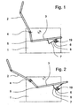
- the braking device shown in the drawing is intended and suitable for a movable component of a furniture element, in particular for a movable component of a seating furniture element, and in particular, as shown here, for the movable seat of a upholstered furniture element, realized in which a coupledstrong- and seat adjustment is.
- FIG. 1 and 2 illustrated embodiment shows first on the support frame 1 of the running here as upholstered seat furniture element a backrest 2 and a seat 3.
- the backrest 2 is pivotally mounted on the support frame 1 to a pivot bearing 4.
- the backrest 2 is pivotally connected to the seat 3 at an angle via a pivot joint 5.
- a cross-beam 6, which carries the seat 3 there.
- located at the front edge of the seat 3 in the region of the crossbeam 6 on each side of the support frame 1 each have a slide 7. In the illustration, however, is due to the Direction of the view shown only a slide 7 to see.
- the seat 3 represents a movable component of a furniture element, here just a upholstered chair.
- a brake bearing block 8 is mounted on the support frame 1, on the cross-beam 6, .
- the brake bearing block 8 forms a sliding guide for the Sliding rail 7.
- the slide 7 thus slides in the transition from the sitting position in the lying position in the brake bearing block 8 with a predetermined sliding friction.
- the movable component of the furniture element here so the seat 3 of the upholstered chair, can be adjusted against a presettable force effect and fix with appropriate design of the braking device from slide 7 and brake pad block 8 in certain positions or lock.
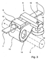
- Fig. 3 shows an overall view of the actual braking device according to the invention
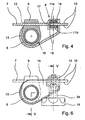
- Fig. 4 shows a longitudinal section through slide rail 7 and brake pad block 8
- Fig. 5 one at right angles to the section of Fig. 4 lying cross section in the region of the brake bearing block 8 shows.
- the braking device according to the invention can be explained in detail.
- the brake bearing block 8 on the one hand, the movable member 3 on the support frame 1, sliding on the slide 7 freely sliding bracket 9, on the other on opposite braking surfaces 10 of the slide 7 coming to rest, pressed against the braking surfaces 10 flat
- the holder 9 is spatially separated from the brake shoes 11, here realized by the holder 9 and the brake shoes 11 being arranged one behind the other in the longitudinal direction of the slide rail 7. This is not mandatory, the arrangement could also be next to each other, if you had a double rail. A single slide 7 is more practical.
- the drawing shows that the brake shoes 11 by means of a clamping means 19, preferably designed as a clamping screw with a well-grip operating knob on the braking surfaces 10 are adjustable.
- the braking force on the braking surfaces 10 of the slide rail 7 is generated by the hiring of the brake shoes 11 to the braking surfaces 10 by means of the clamping means 19 in any case quite predominantly. Static friction of weight thus plays a smaller role in this division than in the prior art.
- a clamping screw as a clamping means 19, one can also provide other means, such as an eccentric lever or a clamping knob. It is essential that the clamping means 19 the As desired setting the brake shoes 11 to the braking surfaces 10, so the compression and holding together of the brake shoes 11 against the braking surfaces 10 makes.
- the slide rail 7 is guided by a recess 12 in the holder 9, which is designed as a compact component, in particular as a component made of reinforced thermoplastic material. It can be seen in the holder 9, the cross-member 6 used there of the support frame 1 in section. On the underside of the movable member 3, so the upholstered furniture of the seat, a slide rail 7 is normally arranged right and left respectively. Accordingly, in each case a holder 9 is arranged on the right and left.
- the braking device according to the invention must be present only on one side, which is sufficient in most cases for effective braking.
- Fig. 4 and 5 show now in the context that here the brake shoes 11, ie an upper brake shoe 11a and a lower brake shoe 11b, are arranged in a receiving housing 13.
- the brake shoe 11a is located above the slide rail 7, the brake shoe 11b below the slide rail 7.
- Each brake shoe 11 is located on a flat side of the slide rail 7, the two flat sides form the braking surfaces 10th
- the plastic provided may be, for example, a polyamide with glass fiber content, for example a polyarylamide PAMXD6 with 60% glass fiber content. This can be sprayed relatively hard with a smooth surface and leads technically and visually to a perfect result.
- a polyamide with glass fiber content for example a polyarylamide PAMXD6 with 60% glass fiber content.
- This can be sprayed relatively hard with a smooth surface and leads technically and visually to a perfect result.
- other compositions are known from the prior art.
- one can produce the receiving housing 13 and / or the housing cover 14 and the holder 9 also made of metal, possibly with a plastic coating.
- Figure 6 shows an end view of the side in the area in which the housing cover 14 is connected to the receiving housing 13.
- This compound is characterized in the illustrated and preferred embodiment, characterized in that the receiving housing 13 and the housing cover 14 are provided with mating form-fitting formations 15 which are in engagement with the housing cover 14 with each other.
- the positive locking formations 15 are here tongue and groove training, which can also be designed as a dovetail formations.
- the form-locking formations 15 may extend over the full length or only over part of the length of the corresponding section.
- the teaching is based on the fact that the holder 9 for suspending the movable component 3 on the support frame 1 on the one hand from the brake bearing block 8 on the other hand is separated.
- the illustrated and preferred embodiment shows a way how you can physically perform this separation, not only spatially, but still achieved in the assembled state again a physical connection.
- the receiving housing 13 additionally has a space 16 for the holder 9 and the holder 9 is coupled to the brake shoes 11 by the arrangement in the space 16 of the receiving housing 13.
- the brake shoes 11 are designed as elongated, transversely over the braking surfaces 10 of the slide rail 7 extending plates. You can see that especially well in Fig. 5 ,
- the brake shoes 11 in the form of the elongated plates as such consist of a material and are treated on the surfaces so that a direct contact with the braking surfaces 10 is possible.
- this could then be provided if the brake shoes 11 as such consist of a fiber-reinforced plastic, optionally additionally mixed with a lubricant, in particular a thermoplastic.
- a lubricant in particular a thermoplastic.
- the illustrated and preferred embodiment of the braking device is structurally a particularly simple structure that ensures a quick assembly.
- the elongated plates forming the brake shoes 11 are mounted at one end in the receiving housing 13 in a plug-in bearing 18. Further, it is provided that the brake shoes 11 forming elongated plates at the other end by means of the clamping means, here the clamping screw 19, are compressible.
- the brake shoes 11 a, 11 b and the elongated plates forming these brake shoes 11 can simply be inserted in the longitudinal direction into the receiving housing 13 and there into the end-side plug-in bearing 18. You have already experienced a prefix in the receiving housing 13.
- the clamping means 19, so here the clamping screw 19, a spacer sleeve 22 is assigned between the brake shoes 11.
- the spacer sleeve 22 may also consist of fiber-reinforced thermoplastic material. It has such a thickness that it defines the minimum distance of the brake shoes 11a, 11b from each other, so that over-tightening of the brake device is reliably avoided.
- the thickness of the spacer sleeve 22 is adapted to the thickness of the slide rail 7, so the distance of the braking surfaces 10 of the slide rail 7 from each other.
- annular groove 23 Indicated on the clamping screw 19 of the illustrated and preferred embodiment is still an annular groove 23. This serves to a transverse pin, which is inserted at the appropriate location in the housing cover 14, record. This in Fig. 5 Without reference numerals indicated transverse pin allows an adjustment of the clamping screw 19 between the edges of the annular groove 23, but prevents accidental unscrewing of the clamping screw 19 from the thread 20a.
- the illustrated and preferred embodiment finally shows a structurally particularly expedient solution such that the housing cover 14 has a jack 24 for the clamping screw 19, in this case such that the housing cover 14 is captively connected to the receiving housing 13 with inserted clamping screw 19.
- the assembly can be seen in Fig. 3 ,
- the jack 24 may also be arranged in the receiving housing 13, which depends on the specific construction.
Abstract
Description
Die Erfindung betrifft eine Bremseinrichtung für ein bewegliches Bauteil eines Möbelelementes, insbesondere eines Polstermöbelelementes, mit den Merkmalen des Oberbegriffs von Anspruch 1 sowie ein Möbelelement mit einer solchen Bremseinrichtung gemäß Anspruch 9.The invention relates to a braking device for a movable component of a furniture element, in particular a upholstered furniture element, with the features of the preamble of
Ein Möbelelement, an dem eine Bremseinrichtung der in Rede stehenden Art verwirklicht werden kann, ist insbesondere ein Polstermöbelelement, nämlich ein Polstersessel. Ein solches Möbelelement ist in verschiedenen Ausführungsformen bekannt (
Um eine Verschiebebewegung des Sitzes nicht unkontrolliert zu erlauben, sondern kontrollierbar zu machen, ist eine Bremseinrichtung zwischen Sitz und Traggestell angeordnet, die eine am beweglichen Bauteil (oder am Traggestell) angebrachte, normalerweise aus Metall bestehende Gleitschiene und einen dieser zugeordneten Bremslagerblock am gegenüberliegenden Bauteil, also am Traggestell (oder am beweglichen Bauteil) aufweist.In order not to allow a sliding movement of the seat uncontrollably, but to make controllable, a braking device between the seat and support frame is arranged, one on the movable member (or on the support frame) mounted, usually made of metal slide rail and one of these associated brake bearing block on the opposite component, So on the support frame (or on the moving component) has.
Hier und im folgenden wird stets ausdrücklich erläutert, daß sich die Gleitschiene am beweglichen Bauteil des Möbelelementes, insbesondere am Sitz des Polstermöbelelementes befindet, während sich der Bremslagerblock am Traggestell befindet. Es gilt aber durchweg auch die kinematische Umkehr, die in den unabhängigen Ansprüchen durch die Klammerausdrücke angedeutet worden ist, daß nämlich der Bremslagerblock am beweglichen Bauteil angebracht ist, während sich die Gleitschiene demgegenüber am Traggestell befindet.Here and below, it is always expressly explained that the slide is on the movable component of the furniture element, in particular the seat of the upholstered furniture element, while the brake bearing block is located on the support frame. However, it is also consistently the kinematic reversal, which has been indicated in the independent claims by the parentheses, namely, that the brake bearing block is attached to the moving component, while the slide rail is in contrast to the support frame.
Im früheren Stand der Technik ist die Bremswirkung der Bremseinrichtung durch Gleitreibung zwischen den Lagerflächen von Gleitschiene und Bremslagerblock erzeugt worden (
Gleichzeitig mit der Bremsfunktion hat der Bremslagerblock eine zweite Funktion, nämlich eine Halterungs- und Aufhängefunktion für das bewegliche Bauteil am Traggestell. Das hat zur Folge, daß auf der jeweils nach oben gerichteten Bremsfläche der Gleitschiene eine erhebliche Kraftwirkung auftritt, so daß die Haftreibung relativ groß ist.Simultaneously with the braking function of the brake bearing block has a second function, namely a support and suspension function for the movable component on the support frame. This has the consequence that on the respective upward braking surface of the slide a significant force effect occurs, so that the static friction is relatively large.
Bei den aus früherem Stand der Technik bekannten Bremseinrichtungen der in Rede stehenden Art besteht somit das Problem, daß die Bremskraft nicht feinfühlig eingestellt werden kann. Insbesondere ist beim Beginn einer Verstellbewegung ein erheblicher Widerstand zu überwinden, wenn Haftreibung in Gleitreibung übergeht (Startruck).In the known from the prior art braking devices of the type in question thus there is the problem that the braking force can not be adjusted sensitively. In particular, at the beginning of an adjustment, a considerable resistance to overcome when static friction passes into sliding friction (Startruck).
Das zuvor genannte Problem hat man dadurch zu lösen versucht (
Es hat sich jedoch in der Praxis gezeigt, daß eine Bremseinrichtung mit Bremsrollen in modern gestalteten Möbelelemente mitunter schwierig zu integrieren ist. Der Raumbedarf ist hoch. Die Einstelleinrichtung für die Bremseinrichtung muß massiv ausgeführt sein, weil für eine wirksame Bremsung der Bremsrollen eine hohe Bremskraft erforderlich ist.However, it has been shown in practice that a braking device with brake rollers in modern designed furniture elements is sometimes difficult to integrate. The space requirement is high. The adjusting device for the braking device must be solid, because a high braking force is required for effective braking of the brake rollers.
Der Lehre liegt daher das Problem zugrunde, eine Bremseinrichtung der eingangs beschriebenen Art mit Bremsflächen und Bremsbacken in Richtung auf einen geringen Startruck und eine gute Einstellbarkeit zu optimieren.The teaching is therefore based on the problem of optimizing a braking device of the type described above with braking surfaces and brake shoes in the direction of a low start truck and good adjustability.
Die zuvor aufgezeigte Problemstellung ist bei einer Bremseinrichtung mit den Merkmalen des Oberbegriffs von Anspruch 1 durch die Merkmale des kennzeichnenden Teils von Anspruch 1 gelöst.The above-indicated problem is solved in a braking device with the features of the preamble of
Erfindungsgemäß ist die das bewegliche Bauteil am Traggestell tragende Halterung von dem eigentlichen Bremslagerblock getrennt. Die Tragfunktion einerseits und die Bremsfunktion andererseits sind voneinander getrennt. Die obere Bremsfläche der Gleitschiene bleibt von Kraft weitgehend frei, die aus der Belastung des beweglichen Bauteils und dessen Aufhängung am Traggestell resultiert. Dadurch ist die Normalkraft auf die betroffene Bremsfläche normalerweise relativ gering. Die Bremskraft an den Bremsflächen wird also tatsächlich nur oder überwiegend durch die Anstellung der Bremsbacken an die Bremsflächen erzeugt und ist dementsprechend feinfühlig einstellbar. Es hat sich gezeigt, daß damit die Einstellbarkeit optimiert und der Startruck wesentlich reduziert werden kann, obwohl man bei der altbekannten konstruktiven Lösung mit Bremsflächen und Bremsbacken bleibt.According to the invention, the support carrying the movable component on the support frame is separated from the actual brake bearing block. The support function on the one hand and the brake function on the other hand are separated. The upper braking surface of the slide remains largely free of force resulting from the loading of the movable member and its suspension on the support frame. As a result, the normal force on the affected braking surface is usually relatively low. The braking force on the braking surfaces is thus actually only or predominantly generated by the employment of the brake shoes to the braking surfaces and is accordingly sensitively adjustable. It has been shown that thus optimizes the adjustability and the starter truck can be significantly reduced, although one remains in the well-known design solution with braking surfaces and brake shoes.
Bei der erfindungsgemäßen Bremseinrichtung erreicht man eine hohe Bremswirkung bereits mit wesentlich geringerer Anstellkraft der Bremsbacken an die Bremsflächen als bei einem System mit Bremsrollen. Die gesamte Konstruktion kann leichter und einfacher aufgebaut sein und ist besser in moderne Möbelelemente zu integrieren.In the braking device according to the invention to achieve a high braking effect already with significantly lower contact force of the brake shoes to the braking surfaces than in a system with brake rollers. The whole construction can be lighter and simpler and better integrated into modern furniture elements.
Bevorzugte Ausgestaltungen und Weiterbildungen der Erfindung sind Gegenstand der abhängigen Unteransprüche. Diese werden im einzelnen im Zusammenhang mit der Erläuterung bevorzugter Ausführungsbeispiele anhand der Zeichnung näher erläutert.Preferred embodiments and further developments of the invention are the subject of the dependent subclaims. These will be explained in detail in connection with the explanation of preferred embodiments with reference to the drawing.
Schließlich ist Gegenstand der Erfindung auch ein Möbelelement mit einer entsprechenden erfindungsgemäßen Bremseinrichtung.Finally, the subject of the invention is also a furniture element with a corresponding braking device according to the invention.
Nachfolgend wird ein bevorzugtes Ausführungsbeispiel der Erfindung anhand der Zeichnung näher erläutert. In der Zeichnung zeigt
- Fig. 1
- ein Ausführungsbeispiel eines Sitzmöbelelementes mit einer erfindungsgemäßen Bremseinrichtung in Sitzstellung,
- Fig. 2
- das Sitzmöbelelement aus
Fig. 1 in Liegestellung, - Fig. 3
- in vergrößerter Darstellung, schematisch, die Bremseinrichtung des Sitzmöbelelements aus
Fig. 1 und Fig. 2 , - Fig. 4
- einen Längsschnitt durch die Bremseinrichtung mit der Gleitschiene,
- Fig. 5
- einen Querschnitt durch Bremseinrichtung und Gleitschiene im Bereich der Bremsbacken,
- Fig. 6
- eine Seitenansicht der Bremseinrichtung im Bereich der Bremsbakken.
- Fig. 1
- An embodiment of a seating furniture element with a braking device according to the invention in sitting position,
- Fig. 2
- the seating furniture element
Fig. 1 in lying position, - Fig. 3
- in an enlarged view, schematically, the braking device of the seating furniture element
Fig. 1 and Fig. 2 . - Fig. 4
- a longitudinal section through the braking device with the slide,
- Fig. 5
- a cross section through braking device and slide rail in the brake shoes,
- Fig. 6
- a side view of the braking device in the field of Bremsbakken.
Die in der Zeichnung dargestellte Bremseinrichtung ist bestimmt und geeignet für ein bewegliches Bauteil eines Möbelelementes, insbesondere für ein bewegliches Bauteil eines Sitzmöbelelementes, und ganz insbesondere, wie hier nämlich dargestellt, für den beweglichen Sitz eines Polstermöbelelementes, bei dem eine gekoppelte Rückenlehnen- und Sitzverstellung realisiert ist.The braking device shown in the drawing is intended and suitable for a movable component of a furniture element, in particular for a movable component of a seating furniture element, and in particular, as shown here, for the movable seat of a upholstered furniture element, realized in which a coupled Rückenlehnen- and seat adjustment is.
Das in
Der Sitz 3 stellt ein bewegliches Bauteil eines Möbelelementes, hier eben eines Polstersessels dar. Am Traggestell 1, an der Quertraverse 6, ist ein Bremslagerblock 8 angebracht. Der Bremslagerblock 8 bildet eine Gleitführung für die Gleitschiene 7. Die Gleitschiene 7 gleitet also beim Übergang von der Sitzstellung in die Liegestellung im Bremslagerblock 8 mit einer vorgegebenen Gleitreibung. Auf diese Weise läßt sich das bewegliche Bauteil des Möbelelementes, hier also der Sitz 3 des Polstersessels, gegen eine voreinstellbare Kraftwirkung verstellen und bei entsprechender Gestaltung der Bremseinrichtung aus Gleitschiene 7 und Bremslagerblock 8 auch in bestimmten Positionen fixieren oder arretieren.The
Vorgesehen ist zunächst, daß der Bremslagerblock 8 zum einen eine das bewegliche Bauteil 3 am Traggestell 1 tragende, auf der Gleitschiene 7 frei gleitend verschiebbare Halterung 9, zum anderen an einander gegenüberliegenden Bremsflächen 10 der Gleitschiene 7 zur Anlage kommende, an die Bremsflächen 10 andrückbare flächige Bremsbacken 11 aufweist. Man erkennt in
Die Zeichnung läßt erkennen, daß die Bremsbacken 11 mittels eines Spannmittels 19, bevorzugt ausgeführt als Spannschraube mit einem gut greifbaren Betätigungsknauf, an die Bremsflächen 10 anstellbar sind. Die Bremskraft an den Bremsflächen 10 der Gleitschiene 7 wird durch das Anstellen der Bremsbacken 11 an die Bremsflächen 10 mittels des Spannmittels 19 jedenfalls ganz überwiegend erzeugt. Haftreibung aus Gewichtskraft spielt bei dieser Aufteilung somit eine geringere Rolle als im Stand der Technik. Anstelle einer Spannschraube als Spannmittel 19 kann man auch andere Mittel vorsehen, beispielsweise einen Exzenterhebel oder einen Spannknebel. Wesentlich ist, daß das Spannmittel 19 das wunschgemäße Anstellen der Bremsbacken 11 an die Bremsflächen 10, also das Zusammendrücken und Zusammenhalten der Bremsbacken 11 gegenüber den Bremsflächen 10 leistet.The drawing shows that the brake shoes 11 by means of a clamping means 19, preferably designed as a clamping screw with a well-grip operating knob on the braking surfaces 10 are adjustable. The braking force on the braking surfaces 10 of the
Es ist gut zu erkennen, daß die Gleitschiene 7 durch eine Ausnehmung 12 in der Halterung 9 geführt ist, die dazu als kompaktes Bauteil, insbesondere als Bauteil aus verstärktem thermoplastischem Kunststoff ausgeführt ist. Man erkennt in der Halterung 9 die dort eingesetzte Quertraverse 6 des Traggestells 1 im Schnitt. An der Unterseite des beweglichen Bauteils 3, also beim Polstermöbel des Sitzes, ist normalerweise rechts und links jeweils eine Gleitschiene 7 angeordnet. Dementsprechend ist rechts und links auch jeweils eine Halterung 9 angeordnet. Die erfindungsgemäße Bremseinrichtung muß nur an einer Seite vorhanden sein, das reicht in den meisten Fällen für eine wirkungsvolle Bremsung aus.It is easy to see that the
Im dargestellten und bevorzugten Ausführungsbeispiel ist das Aufnahmegehäuse 13 nicht einfach einseitig offen ausgebildet. Vielmehr ist vorgesehen, daß das Aufnahmegehäuse 13 einen abnehmbaren Gehäusedeckel 14 aufweist. Im dargestellten und bevorzugten Ausführungsbeispiel ist dabei vorgesehen, daß das Aufnahmegehäuse 13 und der Gehäusedeckel 14 aus einem verstärkten thermoplastischen Kunststoff ausgeführt sind.In the illustrated and preferred embodiment, the receiving
Bei dem vorgesehenen Kunststoff kann es sich beispielsweise um ein Polyamid mit Glasfaseranteil, beispielsweise ein Polyarylamid PAMXD6 mit 60 % Glasfaseranteil handeln. Dieses kann vergleichsweise hart mit glatter Oberfläche gespritzt werden und führt technisch und optisch zu einem einwandfreien Ergebnis. Selbstverständlich sind aus dem Stand der Technik auch andere Zusammensetzungen bekannt. Insbesondere kann man das Aufnahmegehäuse 13 und/oder den Gehäusedeckel 14 sowie die Halterung 9 auch aus Metall, ggf. mit einer Kunststoffbeschichtung, herstellen.The plastic provided may be, for example, a polyamide with glass fiber content, for example a polyarylamide PAMXD6 with 60% glass fiber content. This can be sprayed relatively hard with a smooth surface and leads technically and visually to a perfect result. Of course, other compositions are known from the prior art. In particular, one can produce the receiving
Zuvor ist darauf hingewiesen worden, daß die Lehre darauf abstellt, daß die Halterung 9 zum Aufhängen des beweglichen Bauteils 3 am Traggestell 1 einerseits von dem Bremslagerblock 8 andererseits getrennt ist. Das dargestellte und bevorzugte Ausführungsbeispiel zeigt eine Möglichkeit, wie man diese Trennung auch körperlich, nicht nur räumlich durchführen kann, trotzdem aber in zusammengebautem Zustand wieder eine körperliche Verbindung erzielt. Hier ist vorgesehen, daß das Aufnahmegehäuse 13 zusätzlich einen Raum 16 für die Halterung 9 aufweist und die Halterung 9 mit den Bremsbacken 11 durch die Anordnung im Raum 16 des Aufnahmegehäuses 13 gekuppelt ist.It has previously been pointed out that the teaching is based on the fact that the
Bislang ist zu der Ausgestaltung der Bremsbacken 11 bezüglich der Bremsflächen 10 noch nicht viel erläutert worden. Nach bevorzugter Lehre, die auch im vorliegenden Ausführungsbeispiel verwirklicht ist, empfiehlt es sich, daß die Bremsbacken 11 als langgestreckte, quer über die Bremsflächen 10 der Gleitschiene 7 verlaufende Platten ausgeführt sind. Das erkennt man besonders gut in
Man könnte vorsehen, daß die Bremsbacken 11 in Form der langgestreckten Platten als solche aus einem Material bestehen und an den Oberflächen so behandelt sind, daß unmittelbar eine Anlage auf den Bremsflächen 10 möglich ist. Insbesondere könnte man das dann vorsehen, wenn die Bremsbacken 11 als solche aus einem faserverstärkten, ggf. mit einem Gleitmittel zusätzlich versetzten Kunststoff, insbesondere einem thermoplastischen Kunststoff, bestehen würden. Es hat sich aber in der Praxis gezeigt, daß mitunter derartige Bremsbacken 11 die notwendigen Kräfte nicht zu übertragen vermögen, jedenfalls nicht mit einer hohen Standfestigkeit.It could be provided that the brake shoes 11 in the form of the elongated plates as such consist of a material and are treated on the surfaces so that a direct contact with the braking surfaces 10 is possible. In particular, this could then be provided if the brake shoes 11 as such consist of a fiber-reinforced plastic, optionally additionally mixed with a lubricant, in particular a thermoplastic. However, it has been shown in practice that sometimes such brake shoes 11 the necessary forces can not transfer, at least not with a high stability.
Das dargestellte und bevorzugte Ausführungsbeispiel sieht dementsprechend vor, daß die die Bremsbacken 11 bildenden langgestreckten Platten aus Metall, insbesondere aus oberflächenbehandeltem Stahl oder aus Aluminium, bestehen. Dort, wo die Platten an den Bremsflächen 10 der Gleitschiene 7 zur Anlage kommen, sind sie hier mit einer Gleitauflage 17 in Form eines Gleitplättchens aus Kunststoff versehen. Hier hat man stark widerstandsfähige und auch dauerhaft standfeste Bremsbacken 11, die im eigentlichen Anlagebereich zu den Bremsflächen 10 mit einer passenden Oberfläche versehen sind. Das dargestellte Ausführungsbeispiel zeigt die Gleitauflage 17 auf jeder der Bremsbacken 11 a, 11 b als winkelförmiges Gleitplättchen aus einem faserverstärkten thermoplastischen Kunststoff. Dabei kann es sich im konkreten Ausführungsbeispiel um den selben Kunststoff handeln, der auch für die Halterung 9, das Aufnahmegehäuse 13 und den Gehäusedeckel 14 verwendet worden ist. Zwingend ist das aber nicht. Insbesondere kann die Gleitauflage 17 auch noch Gleitmittel enthalten, die den Startruck ein weiteres Mal zu verringern vermögen, auch wenn sie als Beschichtung ausgeführt ist.The illustrated and preferred embodiment accordingly provides that the elongated plates forming the brake shoes 11 are made of metal, in particular of surface-treated steel or of aluminum. Where the plates come to rest on the braking surfaces 10 of the
Das dargestellte und bevorzugte Ausführungsbeispiel der Bremseinrichtung zeigt konstruktiv einen besonders einfachen Aufbau, der einen schnellen Zusammenbau gewährleistet. Im konkreten Ausführungsbeispiel ist dazu vorgesehen, daß die die Bremsbacken 11 bildenden langgestreckten Platten einenends im Aufnahmegehäuse 13 in einem Stecklager 18 gelagert sind. Ferner ist dabei vorgesehen, daß die die Bremsbacken 11 bildenden langgestreckten Platten anderenends mittels des Spannmittels, hier der Spannschraube 19, zusammendrückbar sind. Die Bremsbacken 11 a, 11b bzw. die diese Bremsbacken 11 bildenden langgestreckten Platten können einfach in Längsrichtung in das Aufnahmegehäuse 13 und dort in das endseitige Stecklager 18 eingesteckt werden. Sie haben damit schon eine Vorfixierung im Aufnahmegehäuse 13 erfahren. Damit läßt sich am anderen Ende der Bremsbacken 11 das Spannmittel 19 einfach anbringen, insbesondere die Spannschraube 19 einfach einsetzen. Man erkennt in
Ferner ist im dargestellten Ausführungsbeispiel vorgesehen, daß dem Spannmittel 19, hier also der Spannschraube 19, eine Distanzhülse 22 zwischen den Bremsbacken 11 zugeordnet ist. Die Distanzhülse 22 kann ebenfalls aus faserverstärktem thermoplastischem Kunststoff bestehen. Sie hat eine solche Dicke, daß sie den minimalen Abstand der Bremsbacken 11a, 11b voneinander definiert, so daß ein Überspannen der Bremseinrichtung sicher vermieden wird. Die Dicke der Distanzhülse 22 ist auf die Dicke der Gleitschiene 7, also den Abstand der Bremsflächen 10 der Gleitschiene 7 voneinander abzustimmen. Insbesondere wird durch die Distanzhülse 22 verhindert, daß die im Stecklager 18 lediglich eingesteckten Enden der die Bremsbacken 11 bildenden Platten durch Überspannen mittels der Spannschraube 19 aus dem Stecklager 18 herausgesprengt werden. Es kann kein Überspannen stattfinden.Furthermore, it is provided in the illustrated embodiment that the clamping means 19, so here the clamping
Angedeutet an der Spannschraube 19 des dargestellten und bevorzugten Ausführungsbeispiels ist noch eine Ringnut 23. Diese dient dazu, einen Querstift, der an passender Stelle in den Gehäusedeckel 14 eingesteckt wird, aufzunehmen. Dieser in
Das dargestellte und bevorzugte Ausführungsbeispiel zeigt schließlich noch eine konstruktiv besonders zweckmäßige Lösung dergestalt, daß der Gehäusedeckel 14 eine Steckfassung 24 für die Spannschraube 19 aufweist, und zwar hier derart, daß der Gehäusedeckel 14 mit dem Aufnahmegehäuse 13 bei eingesteckter Spannschraube 19 unverlierbar verbunden ist. Den Zusammenbau erkennt man in
Wie bereits oben erläutert worden ist empfiehlt es sich, eine erfindungsgemäße Bremseinrichtung an einer Gleitschiene 7 des beweglichen Bauteils 3 anzuordnen. Das reicht für die meisten Fälle aus. Normalerweise wird das in Europa die rechte Seite sein, da man dazu tendiert, mit der rechten Hand eine solche zusätzliche Bedienung vorzunehmen.As has already been explained above, it is recommended to arrange a braking device according to the invention on a
Gegenstand der Erfindung ist auch ein komplettes Möbelelement mit einer beschriebenen Bremseinrichtung. Insbesondere wird es sich dabei um ein Polstermöbelelement, beispielsweise einen Polstersessel oder ein gepolstertes Sofa handeln.The invention is also a complete furniture element with a described braking device. In particular, this will be a upholstered furniture element, for example a upholstered chair or a cushioned sofa.
Claims (9)
- Braking device for a movable component of a furniture element, in particular an upholstered furniture element, that has a supporting framework (1), having at least one sliding rail (7) to be fitted on the movable component (3) or on the supporting framework (1) and
having at least one brake bearing block (8) to be fitted on the supporting framework (1) or on the movable component (3),
wherein the brake bearing block (8) has a mount (9), which supports the movable component (3) on the supporting framework (1) and can be displaced in a freely sliding manner on the sliding rail (7), and also flat brake blocks (11), which come into abutment on opposite braking surfaces (10) of the sliding rail (7),
characterized
in that the mount (9) is spatially separated from the brake blocks (11),
in that the brake blocks (11) can be positioned against the braking surfaces (10) by way of a tensioning means (19)), in particular a tensioning screw, and
in that the braking force on the braking surfaces (10) of the sliding rail (7) is generated only, or predominantly, by the positioning of the brake blocks (11) against the braking surfaces (10) by way of the tensioning means (19). - Braking device according to Claim 1, characterized
in that the mount (9) and the brake blocks (11) are arranged in succession in the longitudinal direction of the sliding rail (7). - Braking device according to Claim 1 or 2,
characterized
in that the mount (9) is designed as a compact component (3), in particular made of reinforced thermoplastic material. - Braking device according to one of Claims 1 to 3,
characterized
in that the brake blocks (11) are arranged in an accommodating housing (13),
wherein, preferably, the accommodating housing (13) has a removable housing cover (14), and/or
wherein, preferably, the accommodating housing (13) and/or the housing cover (14) is/are made of a reinforced thermoplastic material, and/or
wherein, preferably, the accommodating housing (13) and the housing cover (14) are provided with matching positively locking formations (15), which engage with one another when the housing cover (14) is in place,
and/or
wherein, preferably, the accommodating housing (13) additionally has a space (16) for the mount (9) and the mount (9) is coupled to the brake blocks (11) by the accommodating housing (13) being arranged in the space (16). - Braking device according to one of Claims 1 to 4,
characterized
in that the brake blocks (11) are designed as elongate plates running transversely over the braking surfaces (10) of the sliding rail (7),
wherein, preferably, the elongate plates forming the brake blocks (11) consist of metal, in particular of surface-treated steel or of aluminium, and are provided with a sliding support (17), in particular in the form of a coating or of a plastic sliding lamella if appropriate where they come into abutment on the braking surfaces (10) of the sliding rail (7). - Braking device according to Claim 5, characterized
in that the elongate plates forming the brake blocks (11) are mounted at one end in a plug-in bearing (18) in the accommodating housing (13),
wherein, preferably, the elongate plates forming the brake blocks (11) can be pushed together at the other end by way of the tensioning means (19). - Braking device according to one of Claims 1 to 6,
characterized
in that a spacer sleeve (22) between the brake blocks (1-L) is assigned to the tensioning means (19). - Braking device according to one of Claims 1 to 7,
characterized
in that the accommodating housing (13) or, if present, the housing cover (14) has a plug-in socket (24) for the tensioning means (19), preferably such that the housing cover (14) is captively connected to the accommodating housing (13) when the tensioning means (19) is fitted. - Furniture element, in particular an upholstered furniture element, having a supporting framework (1) and a movable component (3) mounted movably on the supporting framework (1), in particular a seat of the upholstered furniture element, and having, for the movable component (3), a braking device which has at least one brake bearing block (8) to be fitted on the supporting framework (1) (or on the movable component (3)),
characterized by
a braking device according to one of Claims 1 to 8 on at least one side, preferably on just one side, of the movable component (3) (or of the supporting framework (1)).
Priority Applications (1)
| Application Number | Priority Date | Filing Date | Title |
|---|---|---|---|
| PL05024610T PL1680977T3 (en) | 2005-01-12 | 2005-11-11 | Braking device for a mobile furniture element |
Applications Claiming Priority (1)
| Application Number | Priority Date | Filing Date | Title |
|---|---|---|---|
| DE200520000463 DE202005000463U1 (en) | 2005-01-12 | 2005-01-12 | Braking device for a movable component of a furniture element |
Publications (3)
| Publication Number | Publication Date |
|---|---|
| EP1680977A2 EP1680977A2 (en) | 2006-07-19 |
| EP1680977A3 EP1680977A3 (en) | 2008-04-23 |
| EP1680977B1 true EP1680977B1 (en) | 2010-05-19 |
Family
ID=34353868
Family Applications (1)
| Application Number | Title | Priority Date | Filing Date |
|---|---|---|---|
| EP05024610A Active EP1680977B1 (en) | 2005-01-12 | 2005-11-11 | Braking device for a mobile furniture element |
Country Status (4)
| Country | Link |
|---|---|
| EP (1) | EP1680977B1 (en) |
| AT (1) | ATE468048T1 (en) |
| DE (2) | DE202005000463U1 (en) |
| PL (1) | PL1680977T3 (en) |
Families Citing this family (2)
| Publication number | Priority date | Publication date | Assignee | Title |
|---|---|---|---|---|
| DE202013002163U1 (en) | 2013-03-07 | 2013-04-22 | Erpo Möbelwerk GmbH | Seating furniture with seat and footboard |
| DE202014010096U1 (en) | 2014-12-23 | 2015-02-06 | Erpo Möbelwerk GmbH | Seating furniture with adjustable legrest |
Family Cites Families (7)
| Publication number | Priority date | Publication date | Assignee | Title |
|---|---|---|---|---|
| DE7302544U (en) | 1973-05-03 | Lusch F | Adjustable deck chair | |
| IT8521436V0 (en) | 1985-04-12 | 1985-04-12 | Salotti Natuzzi Srl | RECLINABLE BACK ARMCHAIR. |
| FI72865C (en) * | 1985-11-22 | 1987-08-10 | Jorma Saarainen | Device for control and locking of seat backrest. |
| DE8534420U1 (en) | 1985-12-06 | 1986-02-06 | Pfalzberger, Heinrich, Basel | Adjustable seating |
| DK9400143U3 (en) | 1994-03-18 | 1994-07-22 | P Schultz & Co As | Brackets for synchronous seat and back control |
| DE19638075C1 (en) * | 1996-08-29 | 1998-02-26 | Jungjohann Thomas | Braking device for a movable component of a furniture element, in particular upholstered furniture element |
| DE29919528U1 (en) * | 1999-11-06 | 2000-01-27 | Steltemeier Josef Gmbh | Seating |
-
2005
- 2005-01-12 DE DE200520000463 patent/DE202005000463U1/en not_active Expired - Lifetime
- 2005-11-11 AT AT05024610T patent/ATE468048T1/en active
- 2005-11-11 DE DE502005009593T patent/DE502005009593D1/en active Active
- 2005-11-11 EP EP05024610A patent/EP1680977B1/en active Active
- 2005-11-11 PL PL05024610T patent/PL1680977T3/en unknown
Also Published As
| Publication number | Publication date |
|---|---|
| EP1680977A2 (en) | 2006-07-19 |
| ATE468048T1 (en) | 2010-06-15 |
| DE202005000463U1 (en) | 2005-03-17 |
| PL1680977T3 (en) | 2010-08-31 |
| DE502005009593D1 (en) | 2010-07-01 |
| EP1680977A3 (en) | 2008-04-23 |
Similar Documents
| Publication | Publication Date | Title |
|---|---|---|
| EP2273902B1 (en) | Downhill engagement and motivity adjustment | |
| EP1358819B1 (en) | Drawer guide | |
| EP2244605A1 (en) | Mechanism for an office chair | |
| EP2668869B1 (en) | Releasable locking element | |
| DE3341402A1 (en) | LOCKABLE TRIPOD TRIPOD | |
| EP1680977B1 (en) | Braking device for a mobile furniture element | |
| DE102017121641A1 (en) | Belt tensioner for longitudinal conveyor | |
| EP4105432A1 (en) | Automatic seal with a guiding means for guiding a push rod and method for positioning the guiding means in a housing of the seal | |
| DE102005019511A1 (en) | Device for automated exchange of stacks at sheet processing unit, comprises carrying bars with open air ducts | |
| DE19638075C1 (en) | Braking device for a movable component of a furniture element, in particular upholstered furniture element | |
| EP1407691A1 (en) | Linear roller bearing | |
| DE10104661B4 (en) | Suspension device for loads moving in the vertical direction, in particular pipes and the like | |
| DE3703008A1 (en) | HEEL LOCKING DEVICE OF A SAFETY SKI BINDING | |
| EP2446780A1 (en) | Chair, in particular an office chair | |
| CH691266A5 (en) | Top roller carrier for drafting systems of spinning machines. | |
| DE102010045809B4 (en) | Device for inserting a fighter in a door or window frame | |
| DE10110868B4 (en) | rolling device | |
| DE102015010990B4 (en) | Suspension or support device for vertically shifting loads, in particular pipes and the like | |
| DE4241369C1 (en) | Pair of car-seat rails for lengthwise adjustment - have spring component attached to them at ends and running in lengthwise direction round guide member | |
| DE19506461C2 (en) | Treatment couch | |
| DE4001724A1 (en) | Mounting for desk lamp - has U=shaped bracket with elastic material rollers that locates over edge of desk | |
| DE4221542C2 (en) | Braked fixed castor | |
| AT404224B (en) | Lying surface for a bed | |
| DE3043620C2 (en) | Clamping device for clamping a machine part on a rod-shaped guide element | |
| DE3744295A1 (en) | Clamping device for the firm clamping of a linearly movable rod |
Legal Events
| Date | Code | Title | Description |
|---|---|---|---|
| PUAI | Public reference made under article 153(3) epc to a published international application that has entered the european phase |
Free format text: ORIGINAL CODE: 0009012 |
|
| AK | Designated contracting states |
Kind code of ref document: A2 Designated state(s): AT BE BG CH CY CZ DE DK EE ES FI FR GB GR HU IE IS IT LI LT LU LV MC NL PL PT RO SE SI SK TR |
|
| AX | Request for extension of the european patent |
Extension state: AL BA HR MK YU |
|
| PUAL | Search report despatched |
Free format text: ORIGINAL CODE: 0009013 |
|
| AK | Designated contracting states |
Kind code of ref document: A3 Designated state(s): AT BE BG CH CY CZ DE DK EE ES FI FR GB GR HU IE IS IT LI LT LU LV MC NL PL PT RO SE SI SK TR |
|
| AX | Request for extension of the european patent |
Extension state: AL BA HR MK YU |
|
| 17P | Request for examination filed |
Effective date: 20080514 |
|
| AKX | Designation fees paid |
Designated state(s): AT BE BG CH CY CZ DE DK EE ES FI FR GB GR HU IE IS IT LI LT LU LV MC NL PL PT RO SE SI SK TR |
|
| GRAP | Despatch of communication of intention to grant a patent |
Free format text: ORIGINAL CODE: EPIDOSNIGR1 |
|
| RAP1 | Party data changed (applicant data changed or rights of an application transferred) |
Owner name: ERPO MOEBELWERK GMBH |
|
| GRAS | Grant fee paid |
Free format text: ORIGINAL CODE: EPIDOSNIGR3 |
|
| GRAA | (expected) grant |
Free format text: ORIGINAL CODE: 0009210 |
|
| AK | Designated contracting states |
Kind code of ref document: B1 Designated state(s): AT BE BG CH CY CZ DE DK EE ES FI FR GB GR HU IE IS IT LI LT LU LV MC NL PL PT RO SE SI SK TR |
|
| REG | Reference to a national code |
Ref country code: GB Ref legal event code: FG4D Free format text: NOT ENGLISH |
|
| REG | Reference to a national code |
Ref country code: CH Ref legal event code: EP |
|
| REG | Reference to a national code |
Ref country code: IE Ref legal event code: FG4D Free format text: LANGUAGE OF EP DOCUMENT: GERMAN |
|
| REF | Corresponds to: |
Ref document number: 502005009593 Country of ref document: DE Date of ref document: 20100701 Kind code of ref document: P |
|
| REG | Reference to a national code |
Ref country code: NL Ref legal event code: T3 |
|
| REG | Reference to a national code |
Ref country code: PL Ref legal event code: T3 |
|
| LTIE | Lt: invalidation of european patent or patent extension |
Effective date: 20100519 |
|
| PG25 | Lapsed in a contracting state [announced via postgrant information from national office to epo] |
Ref country code: ES Free format text: LAPSE BECAUSE OF FAILURE TO SUBMIT A TRANSLATION OF THE DESCRIPTION OR TO PAY THE FEE WITHIN THE PRESCRIBED TIME-LIMIT Effective date: 20100830 Ref country code: SE Free format text: LAPSE BECAUSE OF FAILURE TO SUBMIT A TRANSLATION OF THE DESCRIPTION OR TO PAY THE FEE WITHIN THE PRESCRIBED TIME-LIMIT Effective date: 20100519 Ref country code: LT Free format text: LAPSE BECAUSE OF FAILURE TO SUBMIT A TRANSLATION OF THE DESCRIPTION OR TO PAY THE FEE WITHIN THE PRESCRIBED TIME-LIMIT Effective date: 20100519 |
|
| PG25 | Lapsed in a contracting state [announced via postgrant information from national office to epo] |
Ref country code: SI Free format text: LAPSE BECAUSE OF FAILURE TO SUBMIT A TRANSLATION OF THE DESCRIPTION OR TO PAY THE FEE WITHIN THE PRESCRIBED TIME-LIMIT Effective date: 20100519 Ref country code: IS Free format text: LAPSE BECAUSE OF FAILURE TO SUBMIT A TRANSLATION OF THE DESCRIPTION OR TO PAY THE FEE WITHIN THE PRESCRIBED TIME-LIMIT Effective date: 20100919 Ref country code: LV Free format text: LAPSE BECAUSE OF FAILURE TO SUBMIT A TRANSLATION OF THE DESCRIPTION OR TO PAY THE FEE WITHIN THE PRESCRIBED TIME-LIMIT Effective date: 20100519 Ref country code: FI Free format text: LAPSE BECAUSE OF FAILURE TO SUBMIT A TRANSLATION OF THE DESCRIPTION OR TO PAY THE FEE WITHIN THE PRESCRIBED TIME-LIMIT Effective date: 20100519 |
|
| PG25 | Lapsed in a contracting state [announced via postgrant information from national office to epo] |
Ref country code: GR Free format text: LAPSE BECAUSE OF FAILURE TO SUBMIT A TRANSLATION OF THE DESCRIPTION OR TO PAY THE FEE WITHIN THE PRESCRIBED TIME-LIMIT Effective date: 20100820 Ref country code: CY Free format text: LAPSE BECAUSE OF FAILURE TO SUBMIT A TRANSLATION OF THE DESCRIPTION OR TO PAY THE FEE WITHIN THE PRESCRIBED TIME-LIMIT Effective date: 20100519 |
|
| REG | Reference to a national code |
Ref country code: IE Ref legal event code: FD4D |
|
| PG25 | Lapsed in a contracting state [announced via postgrant information from national office to epo] |
Ref country code: IE Free format text: LAPSE BECAUSE OF FAILURE TO SUBMIT A TRANSLATION OF THE DESCRIPTION OR TO PAY THE FEE WITHIN THE PRESCRIBED TIME-LIMIT Effective date: 20100519 Ref country code: EE Free format text: LAPSE BECAUSE OF FAILURE TO SUBMIT A TRANSLATION OF THE DESCRIPTION OR TO PAY THE FEE WITHIN THE PRESCRIBED TIME-LIMIT Effective date: 20100519 Ref country code: DK Free format text: LAPSE BECAUSE OF FAILURE TO SUBMIT A TRANSLATION OF THE DESCRIPTION OR TO PAY THE FEE WITHIN THE PRESCRIBED TIME-LIMIT Effective date: 20100519 Ref country code: PT Free format text: LAPSE BECAUSE OF FAILURE TO SUBMIT A TRANSLATION OF THE DESCRIPTION OR TO PAY THE FEE WITHIN THE PRESCRIBED TIME-LIMIT Effective date: 20100920 |
|
| PG25 | Lapsed in a contracting state [announced via postgrant information from national office to epo] |
Ref country code: SK Free format text: LAPSE BECAUSE OF FAILURE TO SUBMIT A TRANSLATION OF THE DESCRIPTION OR TO PAY THE FEE WITHIN THE PRESCRIBED TIME-LIMIT Effective date: 20100519 Ref country code: RO Free format text: LAPSE BECAUSE OF FAILURE TO SUBMIT A TRANSLATION OF THE DESCRIPTION OR TO PAY THE FEE WITHIN THE PRESCRIBED TIME-LIMIT Effective date: 20100519 |
|
| PLBE | No opposition filed within time limit |
Free format text: ORIGINAL CODE: 0009261 |
|
| STAA | Information on the status of an ep patent application or granted ep patent |
Free format text: STATUS: NO OPPOSITION FILED WITHIN TIME LIMIT |
|
| PG25 | Lapsed in a contracting state [announced via postgrant information from national office to epo] |
Ref country code: IT Free format text: LAPSE BECAUSE OF FAILURE TO SUBMIT A TRANSLATION OF THE DESCRIPTION OR TO PAY THE FEE WITHIN THE PRESCRIBED TIME-LIMIT Effective date: 20100519 |
|
| 26N | No opposition filed |
Effective date: 20110222 |
|
| REG | Reference to a national code |
Ref country code: DE Ref legal event code: R097 Ref document number: 502005009593 Country of ref document: DE Effective date: 20110221 |
|
| PG25 | Lapsed in a contracting state [announced via postgrant information from national office to epo] |
Ref country code: MC Free format text: LAPSE BECAUSE OF NON-PAYMENT OF DUE FEES Effective date: 20101130 |
|
| PG25 | Lapsed in a contracting state [announced via postgrant information from national office to epo] |
Ref country code: HU Free format text: LAPSE BECAUSE OF FAILURE TO SUBMIT A TRANSLATION OF THE DESCRIPTION OR TO PAY THE FEE WITHIN THE PRESCRIBED TIME-LIMIT Effective date: 20101120 Ref country code: BG Free format text: LAPSE BECAUSE OF FAILURE TO SUBMIT A TRANSLATION OF THE DESCRIPTION OR TO PAY THE FEE WITHIN THE PRESCRIBED TIME-LIMIT Effective date: 20100519 |
|
| REG | Reference to a national code |
Ref country code: DE Ref legal event code: R082 Ref document number: 502005009593 Country of ref document: DE Representative=s name: VON ROHR PATENTANWAELTE PARTNERSCHAFT MBB, DE |
|
| PGFP | Annual fee paid to national office [announced via postgrant information from national office to epo] |
Ref country code: TR Payment date: 20121030 Year of fee payment: 8 |
|
| PG25 | Lapsed in a contracting state [announced via postgrant information from national office to epo] |
Ref country code: BG Free format text: LAPSE BECAUSE OF FAILURE TO SUBMIT A TRANSLATION OF THE DESCRIPTION OR TO PAY THE FEE WITHIN THE PRESCRIBED TIME-LIMIT Effective date: 20100819 |
|
| PG25 | Lapsed in a contracting state [announced via postgrant information from national office to epo] |
Ref country code: TR Free format text: LAPSE BECAUSE OF NON-PAYMENT OF DUE FEES Effective date: 20131111 |
|
| REG | Reference to a national code |
Ref country code: FR Ref legal event code: PLFP Year of fee payment: 11 |
|
| REG | Reference to a national code |
Ref country code: FR Ref legal event code: PLFP Year of fee payment: 12 |
|
| REG | Reference to a national code |
Ref country code: FR Ref legal event code: PLFP Year of fee payment: 13 |
|
| PGFP | Annual fee paid to national office [announced via postgrant information from national office to epo] |
Ref country code: PL Payment date: 20221020 Year of fee payment: 18 Ref country code: BE Payment date: 20221118 Year of fee payment: 18 |
|
| PGFP | Annual fee paid to national office [announced via postgrant information from national office to epo] |
Ref country code: NL Payment date: 20231120 Year of fee payment: 19 Ref country code: LU Payment date: 20231120 Year of fee payment: 19 |
|
| PGFP | Annual fee paid to national office [announced via postgrant information from national office to epo] |
Ref country code: GB Payment date: 20231123 Year of fee payment: 19 |
|
| PGFP | Annual fee paid to national office [announced via postgrant information from national office to epo] |
Ref country code: FR Payment date: 20231120 Year of fee payment: 19 Ref country code: DE Payment date: 20231127 Year of fee payment: 19 Ref country code: CZ Payment date: 20231102 Year of fee payment: 19 Ref country code: CH Payment date: 20231201 Year of fee payment: 19 Ref country code: AT Payment date: 20231121 Year of fee payment: 19 |
|
| PGFP | Annual fee paid to national office [announced via postgrant information from national office to epo] |
Ref country code: PL Payment date: 20231019 Year of fee payment: 19 Ref country code: BE Payment date: 20231120 Year of fee payment: 19 |