EP3543094B1 - Fahrzeugkarosserieunterseitenstruktur - Google Patents
Fahrzeugkarosserieunterseitenstruktur Download PDFInfo
- Publication number
- EP3543094B1 EP3543094B1 EP19163424.5A EP19163424A EP3543094B1 EP 3543094 B1 EP3543094 B1 EP 3543094B1 EP 19163424 A EP19163424 A EP 19163424A EP 3543094 B1 EP3543094 B1 EP 3543094B1
- Authority
- EP
- European Patent Office
- Prior art keywords
- cover
- vehicle
- arm
- enlarged portion
- floor
- Prior art date
- Legal status (The legal status is an assumption and is not a legal conclusion. Google has not performed a legal analysis and makes no representation as to the accuracy of the status listed.)
- Active
Links
Images



Classifications
-
- B—PERFORMING OPERATIONS; TRANSPORTING
- B62—LAND VEHICLES FOR TRAVELLING OTHERWISE THAN ON RAILS
- B62D—MOTOR VEHICLES; TRAILERS
- B62D35/00—Vehicle bodies characterised by streamlining
- B62D35/02—Streamlining the undersurfaces
-
- B—PERFORMING OPERATIONS; TRANSPORTING
- B60—VEHICLES IN GENERAL
- B60G—VEHICLE SUSPENSION ARRANGEMENTS
- B60G7/00—Pivoted suspension arms; Accessories thereof
- B60G7/001—Suspension arms, e.g. constructional features
-
- B—PERFORMING OPERATIONS; TRANSPORTING
- B60—VEHICLES IN GENERAL
- B60G—VEHICLE SUSPENSION ARRANGEMENTS
- B60G2204/00—Indexing codes related to suspensions per se or to auxiliary parts
- B60G2204/40—Auxiliary suspension parts; Adjustment of suspensions
- B60G2204/43—Fittings, brackets or knuckles
- B60G2204/4308—Protecting guards, e.g. for rigid axle damage protection
-
- Y—GENERAL TAGGING OF NEW TECHNOLOGICAL DEVELOPMENTS; GENERAL TAGGING OF CROSS-SECTIONAL TECHNOLOGIES SPANNING OVER SEVERAL SECTIONS OF THE IPC; TECHNICAL SUBJECTS COVERED BY FORMER USPC CROSS-REFERENCE ART COLLECTIONS [XRACs] AND DIGESTS
- Y02—TECHNOLOGIES OR APPLICATIONS FOR MITIGATION OR ADAPTATION AGAINST CLIMATE CHANGE
- Y02T—CLIMATE CHANGE MITIGATION TECHNOLOGIES RELATED TO TRANSPORTATION
- Y02T10/00—Road transport of goods or passengers
- Y02T10/80—Technologies aiming to reduce greenhouse gasses emissions common to all road transportation technologies
- Y02T10/82—Elements for improving aerodynamics
-
- Y—GENERAL TAGGING OF NEW TECHNOLOGICAL DEVELOPMENTS; GENERAL TAGGING OF CROSS-SECTIONAL TECHNOLOGIES SPANNING OVER SEVERAL SECTIONS OF THE IPC; TECHNICAL SUBJECTS COVERED BY FORMER USPC CROSS-REFERENCE ART COLLECTIONS [XRACs] AND DIGESTS
- Y02—TECHNOLOGIES OR APPLICATIONS FOR MITIGATION OR ADAPTATION AGAINST CLIMATE CHANGE
- Y02T—CLIMATE CHANGE MITIGATION TECHNOLOGIES RELATED TO TRANSPORTATION
- Y02T10/00—Road transport of goods or passengers
- Y02T10/80—Technologies aiming to reduce greenhouse gasses emissions common to all road transportation technologies
- Y02T10/88—Optimized components or subsystems, e.g. lighting, actively controlled glasses
Definitions
- the present invention relates to a vehicle-body lower face structure and a vehicle, and specifically relates to the vehicle-body lower face structure in which a torsion beam type of rear suspension comprising a pair of right-and-left trailing arms and a torsion beam connecting the trailing arms is provided and a floor under cover for airflow straightening is attached to a portion of a vehicle body in front of the rear suspension so as to cover a vehicle-body lower face.
- a torsion beam type of rear suspension comprising a pair of right-and-left trailing arms and a torsion beam connecting the trailing arms
- a floor under cover for airflow straightening is attached to a portion of a vehicle body in front of the rear suspension so as to cover a vehicle-body lower face.
- the torsion beam type of rear suspension is known as a structure for suspending a pair of right-and-left rear wheels.
- This torsion beam type of rear suspension comprises a pair of right-and-left trailing arms which extend in a vehicle longitudinal direction and a torsion beam which extends in a vehicle width direction and connects the trailing arms.
- Japanese Patent Laid-Open Publication No. 2012-148647 discloses a vehicle provided with the above-described torsion beam type of rear suspension, in which an arm cover is provided at a lower face of the above-described trailing arm for the purpose of airflow straightening where an airflow of traveling air flowing below a vehicle floor which flows from below the vehicle floor toward an outward side of the rear wheel is deflected so as to flow straightly rearwardly in the vehicle longitudinal direction.
- Japanese Patent Laid-Open Publication No. 2017-39354 discloses a structure which comprises the torsion beam type of rear suspension and a rear under cover for airflow straightening which is provided at a rear vehicle-body lower face.
- an object of the present invention is suppressing disturbance of a vehicle rear airflow properly.
- the present invention is a vehicle-body lower face structure which includes a torsion beam type of rear suspension, a floor under cover for airflow straightening, and a plate-shaped arm cover for airflow straightening.
- the rear suspension includes a pair of right-and-left trailing arms and a torsion beam connecting the trailing arms.
- the floor under cover is attached to a portion of a vehicle body in front of the rear suspension so as to cover a vehicle-body lower face.
- the plate-shaped arm cover is attached to a lower portion of each of the trailing arms of the rear suspension so as to cover a lower face of the trailing arm.
- the arm cover is provided with an arm-cover enlarged portion which is configured to protrude outwardly, in a vehicle width direction, from the trailing arm in a vehicle bottom-face view.
- a rear end portion of the floor under cover is configured to face to a front edge of the arm-cover enlarged portion of the arm cover.
- the rear end portion of the floor under cover is configured to face closely to the front edge of the arm-cover enlarged portion of the arm cover.
- the rear end portion of the floor under cover is positioned in front of the arm cover.
- the floor under cover is provided with a floor-under-cover enlarged portion such that the rear end portion of the floor under cover faces the front edge of the arm-cover enlarged portion.
- an outward edge, in the vehicle width direction, of the floor-under-cover enlarged portion and an outward-side edge, in the vehicle width direction, of the arm-cover enlarged portion are configured to be continuous or substantially continuous to each other in the vehicle longitudinal direction.
- outward edge of the floor-under-cover enlarged portion and the outward-side edge of the arm-cover enlarged portion are configured to go around an inward-side face of a front portion of a tire of a rear wheel in a curved shape.
- outward edge of the floor-under-cover enlarged portion and the outward-side edge of the arm-cover enlarged portion are configured to be spaced apart from the rear wheel tire.
- the arm-cover enlarged portion is configured such that the outward-side edge, in the vehicle width direction, thereof is extended into a rim of the rear wheel in the vehicle bottom-face view.
- the arm-cover enlarged portion is configured as a cantilever structure such that the arm-cover enlarged portion protrudes toward the rim of the rear wheel beyond an outward end portion, in the vehicle width direction, of the trailing arm.
- a vertical wall portion which extends upwardly is provided at least at the outward-side edge, in the vehicle width direction, of the arm-cover enlarged portion of the arm cover.
- a vehicle includes the above vehicle-body lower face structure.
- the present invention is a vehicle-body lower face structure, comprising a torsion beam type of rear suspension comprising a pair of right-and-left trailing arms and a torsion beam connecting the trailing arms, a floor under cover for airflow straightening attached to a portion of a vehicle body in front of the rear suspension so as to cover a vehicle-body lower face, and a plate-shaped arm cover for airflow straightening attached to a lower portion of each of the trailing arms of the rear suspension so as to cover a lower face of the trailing arm, wherein the arm cover is provided with an arm-cover enlarged portion which is configured to protrude outwardly, in a vehicle width direction, from the trailing arm in a vehicle bottom-face view, and the floor under cover is provided with a floor-under-cover enlarged portion such that a rear end portion of the floor under cover which is positioned in front of the arm cover faces closely to a front edge of the arm-cover enlarged portion of the arm cover.
- a gap through which the position below the vehicle floor and an inside of the rear wheel house are connected i.e., the gap formed among the inward edge of the rear wheel tire, the rear end portion of the floor under cover, and the front end portion of the arm cover
- the gap formed among the inward edge of the rear wheel tire, the rear end portion of the floor under cover, and the front end portion of the arm cover is so reduced by the enlarged portion of the arm cover and the enlarged portion of the floor under cover that the traveling air flowing below the vehicle floor can be properly suppressed from flowing into the rear wheel house, thereby suppressing the disturbance of the vehicle rear airflow properly.
- the above-described arm-cover enlarged portion is configured such that the outward-side edge, in the vehicle width direction, thereof is extended into a rim of the rear wheel in the vehicle bottom-face view, suppressing of the traveling air flowing below the vehicle floor from flowing into the rear wheel house by means of the arm-cover enlarged portion can be more effective.
- a rear-end side of the floor under cover and a front-end side of the arm cover are configured to face closely to each other in a vehicle longitudinal direction, and an outward edge, in the vehicle width direction, of the floor-under-cover enlarged portion and an outward-side edge, in the vehicle width direction, of the arm-cover enlarged portion are configured to go around an inward-side face of a front portion of a tire of a rear wheel in a curved shape, being spaced apart from the rear wheel tire, and be continuous to each other in the vehicle longitudinal direction.
- the arm-cover enlarged portion is configured as a cantilever structure such that the arm-cover enlarged portion protrudes toward the rim of the rear wheel beyond an outward end portion, in the vehicle width direction, of said trailing arm, and a vertical wall portion which extends upwardly is provided at least at the outward-side edge, in the vehicle width direction, of the arm-cover enlarged portion of the arm cover.
- the strength of the arm cover can be effectively increased by the vertical wall portion even if the arm-cover enlarged portion of the arm cover is configured as the cantilever structure.
- FIG. 1 is a side view of a vehicle which is provided with the vehicle-body lower face structure
- FIG. 2 is a bottom view of a major part of FIG. 1
- FIG. 3 is an enlarged view of a vehicle left-side part of FIG. 2
- FIG. 4 is a side view showing a related structure of a floor under cover and an arm cover
- FIG. 5 is a sectional view taken along line A-A of FIG. 3
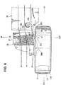
- FIG. 6 is a major-part enlarged bottom-face view showing an airflow of traveling air flowing below a vehicle floor of the present embodiment
- FIG. 7A is a bottom-face perspective view showing an airflow of traveling air flowing below a vehicle floor of the present embodiment
- FIG. 7B is a bottom-face perspective view showing an airflow of the traveling air flowing below the vehicle floor of an comparative example.
- a side portion of a vehicle body are provided one or more doors, particularly a front door 2 as a side door which is configured to open or close a front door opening 1 which is formed at a vehicle front portion and a rear door 4 as another side door which is configured to open or close a rear door opening 3 which is formed at a vehicle rear portion.
- the front door 2 is particularly equipped with a door outer handle 5
- the rear door 4 is particularly equipped with another door outer handle 6 similarly.
- a front fender panel 7 which covers a side of an engine room is particularly provided in front of the front door 2 , and a front wheel house 9 is integrally formed at a lower portion of the front fender panel 7 at a position adjacent or corresponding to a front wheel 8 .
- a rear fender panel 10 which covers a side of a baggage compartment is particularly provided in back of the rear door 4 , and a rear wheel house 12 is integrally formed at a lower portion of the rear fender panel 10 at a position adjacent to or corresponding to a rear wheel 11 .
- reference character 13 denotes a door mirror
- reference character 14 denotes a rear bumper face which is particularly configured to extend rearwardly, going around a vehicle side portion.
- a pair of right-and-left side sills 15 are provided.
- the pair of right-and-left side sills 15 extend in a vehicle longitudinal direction at a lower portion of a cabin at a position between a lower end portion of a rear edge of the front wheel house 9 and a lower end portion of a front edge of the rear wheel house 12 .
- the side sill 15 is particularly a vehicle-body reinforcing member having a side-sill closed cross section, which is formed by fixedly joining a side sill outer and a side sill inner 15a (see FIG. 3 ) and extends in the vehicle longitudinal direction.
- a pair of garnishes 16, 16 are particularly attached to the above-described pair of right-and-left side sills 15 such that each garnish 16 covers each side sill 15 over a range from the front wheel house 9 to the rear wheel house 12 .
- a tire deflector 17 is particularly provided at a rear end portion of the garnish 1 6 such that the tire deflector 17 faces a front portion of the rear wheel 11 inside the rear wheel house 12 .
- This tire deflector 17 is particularly configured to deflect a side-face airflow flowing at a vehicle-body side portion such that the side-face airflow is turned toward an outward side, in the vehicle width direction, so as not to flow into the rear wheel house 12 and adheres to an outer face of a tire wheel of the rear wheel 12 .
- the above-described rear wheel house 12 is particularly formed by fixedly joining a wheel house outer 12A and a wheel house inner 12B , and a wheel-house mudguard 12C is particularly provided at a face of the rear wheel house 12 which faces the rear wheel 11 .
- a floor panel 18 which forms respective bottom faces of a cabin and a baggage compartment, particularly comprises a front floor panel, a rear seat pan, and a rear floor panel including a baggage-room recess portion, which are configured to be continuous in the vehicle longitudinal direction.
- the side sill 15 which extends in the vehicle longitudinal direction from the above-described front floor panel to a middle position, in a longitudinal direction, of the rear seat pan, is particularly fixedly joined to a side portion, in the vehicle width direction, of the floor panel 18 .
- a rear side frame 19 is provided.
- the rear side frame 19 extends in the vehicle longitudinal direction from a middle position, in a longitudinal direction, of the above-described rear seat pan to a rear end of the rear floor panel.
- the rear side frame 19 particularly comprises a rear side frame upper 20 and a rear side frame lower 21 , and a rear-side-frame closed cross section S1 which extends in the vehicle longitudinal direction is particularly formed between the rear side frame upper 20 and the rear side frame lower 21 .
- a rear cross member 22 which extends in the vehicle width direction is particularly provided to be laid between the right-and-left rear side frames 19 , 19 at a longitudinal position in back of a central portion of the rear wheel 11 , and the right-and-left rear side frame lowers 21, 21 are particularly interconnected by this rear cross member 22 .
- an exhaust pipe 30 to guide rearwardly exhaust gas which is discharged from exhaust ports and an exhaust manifold of an engine is particularly provided at a tunnel portion below the vehicle floor.
- This exhaust pipe 30 is particularly provided with a catalyst convertor 31 , a silencer 32 is connected to a rear end portion of the exhaust pipe 30 which extends to a position behind the rear cross member 22 , and a pair of tail pipes 33 , 33 are attached to right-and-left both sides of the silencer 32 .
- This tail pipe 33 is particularly configured in an L shape such that it extends outwardly in the vehicle width direction and then extends rearwardly.
- a cover for airflow straightening 34 is provided to cover between an outward side, in the vehicle width direction, of a front portion of the silencer 32 and a corner portion of the tail pipe 33 from below.
- one or more floor under covers for air flow straightening particularly a pair of right-and-left floor under covers for airflow straightening 35 , 36 which cover another portion of the vehicle-body lower face than the tunnel portion are provided.
- Each of the floor under covers 35 , 36 particularly has a flat airflow-straightening face at its bottom face.
- the front-and-rear floor under covers 35 , 36 are particularly configured to be continuous or substantially continuous to each other in the vehicle longitudinal direction.
- a torsion beam type of rear suspension 40 which suspends a pair of right-and-left rear wheels 11 is provided.
- the rear suspension 40 comprises a pair of right-and-left trailing arms 41, 41 extending in the vehicle longitudinal direction and a torsion beam 42 (torsional bar spring) which extends in the vehicle width direction and interconnects the trailing arms 41, 41.
- the torsion beam 42 is particularly configured to have a hollow closed cross section.
- the trailing arm 41 is particularly configured to have a closed cross section by fixedly joining a trailing arm outer 43 and a trailing arm inner 44 .
- a coil spring 46 as a suspension spring is particularly provided to extend between a lower spring seat (not illustrated) which is fixedly joined to an inward side, in the vehicle width direction, of the trailing arm 41 and a rear face portion of the torsion beam 42 and an upper spring seat 45 which fixedly attached to a lower face of the rear side frame lower 21 of the rear side frame 19 .
- a damper 47 is particularly provided to extend between a rear-end-side upper portion of the trailing arm 41 and a vehicle-body side (a damper attachment portion of an upper portion of a wheel arch of the rear wheel house 12 ).
- a plate-shaped arm cover for airflow straightening 50 which covers a lower face of the trailing arm 41 is attached to a lower portion of the training arm 41 .
- the above-described floor under covers 35, 36 are covers for airflow straightening which are provided to cover respective vehicle-body lower faces positioned in front of the rear suspension 40 .
- the arm cover 50 is particularly attached to a lower face of the trailing arm 41 or a lower face of the lower spring seat by using attaching members, such as bolts 51, 52, 53, and a bracket such that the arm cover 50 moves together with the trailing arm 41 .
- the above-described bolt 51 is particularly positioned at the outward side, in the vehicle width direction, of a front portion of the arm cover 50
- the above-described bolt 52 is positioned at the inward side, in the vehicle width direction, of a middle portion, in the vehicle longitudinal direction, of the arm cover 50
- the above-described bolt 53 is positioned at the outward side, in the vehicle width direction, of a rear portion of the arm cover 50 .
- these bolts 51, 52, 53 are particularly disposed at recess portions 54, 55, 56 which are configured to be concaved upwardly such that respective head portions of the bolts 54, 55, 56 do not protrude downwardly from the lower face of the arm cover, i.e., from an airflow-straightening face.
- the rear wheel 11 particularly comprises a rim 11R and a tire 11T as shown in FIG. 5 .
- the arm cover 50 is provided with an arm-cover enlarged portion 50A which is configured such that an outward edge, in the vehicle width direction, of the arm cover 50 is extended (protrudes) into the rim 1 1R of the rear wheel 11 .
- the arm-cover enlarged portion 50A particularly protrudes into the rim 11R , i.e., a space surrounded by the rim 11R , up to a position of about 18% - about 20% of a rim width in the present embodiment, but this protrusion magnitude is not limited to this range.
- FIG. 7B which is the bottom-face perspective view showing the airflow of the traveling air flowing below the vehicle floor of the comparative example
- the same reference characters as those used in FIG. 7A are used for convenience's shake of describing the example.
- imaginary lines ⁇ 1, ⁇ 2 show shapes of the comparative example (see FIG. 7B ).
- imaginary lines ⁇ 1, ⁇ 2 show a shape of the embodiment (see FIG. 7A ).
- the traveling air flowing below the vehicle floor which flows along the under cover 50 is sucked out by the vehicle-body side-face airflow having a high flow speed, so that there occurs an airflow which flows upwardly and into the rim 11R of the rear wheel 11 from the outward edge, in the vehicle width direction, of the under cover 50 .
- the traveling air flows upwardly and into the rear wheel 11 from the outward edge, in the vehicle width direction, of the arm cover 50 it is suppressed by the arm-cover enlarged portion 50A that the traveling air flows upwardly and into the rear wheel 11 from the outward edge, in the vehicle width direction, of the arm cover 50 .
- the arm-cover enlarged portion 50A of the arm cover 50 is configured to protrude (be extended) outwardly, in the vehicle width direction, from the trailing arm outer 43 of the trailing arm 41 in a vehicle-face bottom view.
- the floor under cover 36 is particularly provided with a floor-under-cover enlarged portion 36A such that a rear end portion 36a of the floor under cover 36 , which is particularly positioned in front of the arm cover 50 , faces to, particularly faces closely to a front edge 50a of the arm-cover enlarged portion 50A of the arm cover 50 .
- a gap through which the position below the vehicle floor and the rear wheel house 12 are connected i.e., the gap formed among the inward edge of the rear wheel tire 11T , the rear end portion 36a of the floor under cover 36 , and a front end portion 50a of the arm cover 50
- the arm-cover enlarged portion 50A of the arm cover 50 and the floor-under-cover enlarged portion 36A of the floor under cover 36 such that the traveling air flowing below the vehicle floor is suppressed from flowing into the rear wheel house 12 , thereby suppressing the disturbance of the vehicle rear airflow.
- a rear-end side 36b of the floor under cover 36 and a front-end side 50b of the arm cover 50 are configured to face to, particularly face closely to each other in parallel, and an outward edge 36c , in the vehicle width direction, of the floor-under-cover enlarged portion 36A of the floor under cover 36 and an outward-side edge 36c , in the vehicle width direction, of the arm-cover enlarged portion 50A of the arm cover 50 are particularly configured to go around an inward-side face of a front portion of the tire 11T of the rear wheel 11 in a curved shape, being spaced apart from the rear wheel tire 11T , and be continuous or substantially continuous to each other in the vehicle longitudinal direction.
- the arm-cover enlarged portion 50A of the arm cover 50 is particularly configured to protrude toward the rim 11R of the rear wheel 11 beyond an outward-side end portion of the trailing arm outer 43 of the trailing arm 41 , and a vertical wall portion 50d which extends upwardly is particularly provided at least at an outward edge, in the vehicle width direction, of the arm-cover enlarged portion 50A of the arm cover 50 .
- another vertical wall portion 50e which extends upwardly is particularly provided at an inward edge, in the vehicle width direction, of the arm cover 50 as well.
- the arm cover 50 is particularly made of synthetic resin, such as polypropylene, and the above-described vertical wall portions 50d, 50e are integrally formed at a body of the arm cover 50 .
- the strength of the arm cover 50 is effectively increased by the vertical wall portion 50d even if the arm-cover enlarged portion 50A of the arm cover 50 is configured as a cantilever structure.
- reference character 60 denotes a rear under cover which particularly attains airflow straightening between a bottom face of the silencer 32 and a bottom face of the rear bumper face 14
- reference character 61 denotes a fuel tank
- reference character 62 denotes a heat insulator which is particularly provided between the silencer 32 and the floor panel 18 .
- an arrow F shows a vehicle forward side
- an arrow R shows a vehicle rearward side
- an arrow IN shows an inward side in the vehicle width direction
- an arrow OUT shows an outward side in the vehicle width direction
- an arrow UP shows a vehicle upward side.
- a vehicle-left side structure is exemplified as the vehicle-body lower face structure in the above-described embodiment
- a vehicle-right side structure is configured to be similar to the vehicle-left side structure.
- the vehicle-body lower face structure of the above-described embodiment comprises the torsion beam type of rear suspension 40 comprising a pair of right-and-left trailing arms 41 and the torsion beam 42 connecting the trailing arms 41 , the floor under cover for airflow straightening 36 attached to the portion of the vehicle body in front of the rear suspension 40 so as to cover the vehicle-body lower face, and the plate-shaped arm cover for airflow straightening 50 attached to the lower portion of each of the trailing arms 41 of the rear suspension 40 so as to cover the lower face of the trailing arm 41 , wherein the arm cover 50 is provided with the arm-cover enlarged portion 50A which is configured to protrude outwardly, in the vehicle width direction, from the trailing arm 41 in the vehicle bottom-face view, and the floor under cover 36 is provided with the floor-under-cover enlarged portion 36A such that the rear end portion 36a of the floor under cover 36 which is positioned in front of the arm cover 50 faces closely to the front edge 50a of the arm-cover enlarged portion 50A
- the gap through which the position below the vehicle floor and the inside of the rear wheel house 12 are connected i.e., the gap formed among the inward edge of the tire of the rear wheel 11 , the rear end portion 36a of the floor under cover 36 , and the front end portion of the arm cover 50 ) is so reduced by the enlarged portion 50A of the arm cover 50 and the enlarged portion 36A of the floor under cover 36 that the traveling air flowing below the vehicle floor can be suppressed from flowing into the rear wheel house 12 , thereby suppressing the disturbance of the vehicle rear airflow.
- the above-described arm-cover enlarged portion 50A is configured such that the outward-side edge 50c , in the vehicle width direction, thereof is extended into the rim 11R of the rear wheel 11 in the vehicle bottom-face view, suppressing of the traveling air flowing below the vehicle floor from flowing into the rear wheel house 12 by means of the arm-cover enlarged portion 50A can be more effective.
- the rear-end side 36b of the floor under cover 36 and the front-end side 50b of the arm cover 50 are configured to face closely to each other in the vehicle longitudinal direction, and the outward edge 36c , in the vehicle width direction, of the floor-under-cover enlarged portion 36A and the outward-side edge 36c , in the vehicle width direction, of the arm-cover enlarged portion 36A are configured to go around the inward-side face of the front portion of the tire 11T of the rear wheel 11 in the curved shape, being spaced apart from the rear wheel tire 11T , and be continuous to each other in the vehicle longitudinal direction (see FIG. 3 ).
- the arm-cover enlarged portion 50A is configured as the cantilever structure such that the arm-cover enlarged portion 50A protrudes toward the rim of the rear wheel beyond the outward end portion, in the vehicle width direction, of the trailing arm 41 , and the vertical wall portion 50d which extends upwardly is provided at least at the outward-side edge, in the vehicle width direction, of the arm-cover enlarged portion 50A of the arm cover 50 (see FIG. 5 ).
- the strength of the arm cover 50 can be effectively increased by the vertical wall portion 50d even if the arm-cover enlarged portion 50A of the arm cover 50 is configured as the cantilever structure.
Landscapes
- Engineering & Computer Science (AREA)
- Mechanical Engineering (AREA)
- Chemical & Material Sciences (AREA)
- Combustion & Propulsion (AREA)
- Transportation (AREA)
- Body Structure For Vehicles (AREA)
Claims (11)
- Fahrzeugkarosserieunterseitenstruktur, umfassend:eine Hinterradaufhängung (40) vom Torsionsträgertyp, die ein Paar von Rechts-Links-Längslenkern (41) und einen Torsionsträger (42), der die Längslenker (41) verbindet, umfasst;eine Unterbodenabdeckung (36) zur Luftstrombegradigung, die an einem Abschnitt einer Fahrzeugkarosserie vor der Hinterradaufhängung (40) befestigt ist, um eine Fahrzeugkarosserieunterseite abzudecken; undeine plattenförmige Lenkerabdeckung (50) zur Luftstrombegradigung, die an einem unteren Abschnitt von jedem der Längslenker (41) der Hinterradaufhängung (40) befestigt ist, um eine Unterseite des Längslenkers (41) abzudecken,wobeidie Lenkerabdeckung (50) mit einem erweiterten Lenkerabdeckungsabschnitt (50A) versehen ist, der so ausgestaltet ist, dass er, in einer Fahrzeugbodenseitenansicht, in einer Fahrzeugbreitenrichtung von dem Längslenker (41) nach außen vorsteht, undein hinterer Endabschnitt (36a) der Unterbodenabdeckung (36) so ausgestaltet ist, dass er einer Vorderkante (50a) des erweiterten Lenkerabdeckungsabschnitts (50A) der Lenkerabdeckung (50) gegenüberliegt.
- Fahrzeugkarosserieunterseitenstruktur nach Anspruch 1, wobei der hintere Endabschnitt (36a) der Unterbodenabdeckung (36) so ausgestaltet ist, dass er einer Vorderkante (50a) des erweiterten Lenkerabdeckungsabschnitts (50A) der Lenkerabdeckung (50) eng gegenüberliegt.
- Fahrzeugkarosserieunterseitenstruktur nach Anspruch 1 oder 2, wobei der hintere Endabschnitt (36a) der Unterbodenabdeckung (36) vor der Lenkerabdeckung (50) positioniert ist.
- Fahrzeugkarosserieunterseitenstruktur nach einem beliebigen der vorhergehenden Ansprüche, wobei die Unterbodenabdeckung (36) mit einem erweiterten Unterbodenabdeckungsabschnitt (36A) derart versehen ist, dass der hintere Endabschnitt (36a) der Unterbodenabdeckung (36) der Vorderkante (50a) des erweiterten Lenkerabdeckungsabschnitts (50A) gegenüberliegt.
- Fahrzeugkarosserieunterseitenstruktur nach Anspruch 4, wobei eine in der Fahrzeugbreitenrichtung nach außen gerichtete Kante des erweiterten Unterbodenabdeckungsabschnitts (36A) und eine in der Fahrzeugbreitenrichtung außenseitige Kante des erweiterten Lenkerabdeckungsabschnitts (50A) so ausgestaltet sind, dass sie in der Fahrzeuglängsrichtung kontinuierlich oder im Wesentlichen kontinuierlich zueinander sind.
- Fahrzeugkarosserieunterseitenstruktur nach Anspruch 5, wobei die nach außen gerichtete Kante des erweiterten Unterbodenabdeckungsabschnitts (36A) und die außenseitige Kante des erweiterten Lenkerabdeckungsabschnitts (50A) so ausgestaltet sind, dass sie in einer gekrümmten Form um eine innenseitige Fläche eines vorderen Abschnitts eines Reifens (11T) eines Hinterrads (11) verlaufen.
- Fahrzeugkarosserieunterseitenstruktur nach Anspruch 6, wobei die nach außen gerichtete Kante des erweiterten Unterbodenabdeckungsabschnitts (36A) und die außenseitige Kante des erweiterten Lenkerabdeckungsabschnitts (50A) so ausgestaltet sind, dass sie von dem Hinterradreifen (11T) beabstandet sind.
- Fahrzeugkarosserieunterseitenstruktur nach Anspruch 6 oder 7, wobei der erweiterte Lenkerabdeckungsabschnitt (50A) derart ausgestaltet ist, dass die in der Fahrzeugbreitenrichtung außenseitige Kante davon in der Fahrzeugbodenseitenansicht in eine Felge (11R) des Hinterrads (11) hinein erstreckt ist.
- Fahrzeugkarosserieunterseitenstruktur nach Anspruch 8, wobei der erweiterte Lenkerabdeckungsabschnitt (50A) als eine Auslegerstruktur derart ausgestaltet ist, dass der erweiterte Lenkerabdeckungsabschnitt (50A) in Richtung der Felge (11R) des Hinterrads (11) über einen in der Fahrzeugbreitenrichtung nach außen gerichteten Endabschnitt des Längslenkers (41) hinaus vorsteht.
- Fahrzeugkarosserieunterseitenstruktur nach einem der Ansprüche 5 bis 9, wobei ein vertikaler Wandabschnitt (50d), der sich nach oben erstreckt, zumindest an der in der Fahrzeugbreitenrichtung außenseitigen Kante des erweiterten Lenkerabdeckungsabschnitts (50A) der Lenkerabdeckung (50) vorgesehen ist.
- Fahrzeug, umfassend:
die Fahrzeugkarosserieunterseitenstruktur nach einem beliebigen der vorhergehenden Ansprüche.
Applications Claiming Priority (2)
| Application Number | Priority Date | Filing Date | Title |
|---|---|---|---|
| JP2018056453A JP7087526B2 (ja) | 2018-03-23 | 2018-03-23 | 車体下面構造 |
| JP2018056454A JP7087527B2 (ja) | 2018-03-23 | 2018-03-23 | 車体下面構造 |
Publications (2)
| Publication Number | Publication Date |
|---|---|
| EP3543094A1 EP3543094A1 (de) | 2019-09-25 |
| EP3543094B1 true EP3543094B1 (de) | 2020-11-04 |
Family
ID=65818317
Family Applications (1)
| Application Number | Title | Priority Date | Filing Date |
|---|---|---|---|
| EP19163424.5A Active EP3543094B1 (de) | 2018-03-23 | 2019-03-18 | Fahrzeugkarosserieunterseitenstruktur |
Country Status (3)
| Country | Link |
|---|---|
| US (1) | US10787208B2 (de) |
| EP (1) | EP3543094B1 (de) |
| CN (1) | CN110294031B (de) |
Families Citing this family (4)
| Publication number | Priority date | Publication date | Assignee | Title |
|---|---|---|---|---|
| JP6508278B2 (ja) * | 2017-09-28 | 2019-05-08 | マツダ株式会社 | 車体下部構造 |
| US10933926B2 (en) * | 2018-05-15 | 2021-03-02 | Mahindra & Mahindra Limited | Twist beam air guided tunnel diffuser |
| USD1024886S1 (en) * | 2021-11-24 | 2024-04-30 | Bayerische Motoren Werke Aktiengesellschaft | Rear fender for a vehicle |
| US12091091B2 (en) * | 2022-03-29 | 2024-09-17 | Honda Motor Co., Ltd. | Disk inner fender undercover |
Family Cites Families (13)
| Publication number | Priority date | Publication date | Assignee | Title |
|---|---|---|---|---|
| JP4655654B2 (ja) * | 2005-02-04 | 2011-03-23 | 日産自動車株式会社 | 車体下部構造 |
| DE102009022684A1 (de) * | 2009-05-26 | 2010-12-02 | Bayerische Motoren Werke Aktiengesellschaft | Luftleiteinrichtung |
| JP5235220B2 (ja) * | 2011-01-18 | 2013-07-10 | 本田技研工業株式会社 | 車両の空気整流カバー |
| JP5853666B2 (ja) * | 2011-12-20 | 2016-02-09 | マツダ株式会社 | 車両の車体下部構造 |
| GB2510580A (en) * | 2013-02-07 | 2014-08-13 | Nissan Motor Mfg Uk Ltd | An aerodynamic beam axle cover for a vehicle |
| DE102013006253A1 (de) * | 2013-04-11 | 2014-10-16 | Audi Ag | Verfahren zur Herstellung einer Luftleiteinrichtung für einen Fahrwerkslenker und Fahrwerkslenker mit einer Luftleiteinrichtung |
| DE102013219211A1 (de) * | 2013-09-24 | 2015-03-26 | Bayerische Motoren Werke Aktiengesellschaft | Unterboden-Verkleidungsteil einer Radachse und Baugruppe mit einem Unterboden-Verkleidungsteil |
| DE102014003305A1 (de) * | 2014-03-08 | 2015-09-10 | Audi Ag | Abdeckung für einen Fahrwerkslenker |
| DE102014014834A1 (de) * | 2014-10-07 | 2016-04-07 | Audi Ag | Fahrwerkslenker mit einer Luftleiteinrichtung |
| JP6292191B2 (ja) | 2015-08-18 | 2018-03-14 | マツダ株式会社 | 自動車の下部整流構造 |
| JP6292192B2 (ja) * | 2015-08-18 | 2018-03-14 | マツダ株式会社 | 自動車の下部整流構造 |
| JP6308196B2 (ja) * | 2015-11-06 | 2018-04-11 | マツダ株式会社 | 自動車の後部整流構造 |
| JP6315038B2 (ja) * | 2016-08-22 | 2018-04-25 | マツダ株式会社 | 自動車の整流構造 |
-
2019
- 2019-03-08 CN CN201910175884.7A patent/CN110294031B/zh active Active
- 2019-03-18 EP EP19163424.5A patent/EP3543094B1/de active Active
- 2019-03-22 US US16/362,358 patent/US10787208B2/en active Active
Also Published As
| Publication number | Publication date |
|---|---|
| CN110294031B (zh) | 2021-08-03 |
| CN110294031A (zh) | 2019-10-01 |
| US10787208B2 (en) | 2020-09-29 |
| EP3543094A1 (de) | 2019-09-25 |
| US20190291524A1 (en) | 2019-09-26 |
Similar Documents
| Publication | Publication Date | Title |
|---|---|---|
| EP3543094B1 (de) | Fahrzeugkarosserieunterseitenstruktur | |
| JP6164249B2 (ja) | 自動車の前部床下整流構造 | |
| EP2740651B1 (de) | Seitenstruktur für eine fahrzeugkarosserie | |
| US20160236721A1 (en) | Upper vehicle-body structure of vehicle | |
| EP3543093B1 (de) | Fahrzeugkarosserieunterseitenstruktur | |
| US10899388B2 (en) | Vehicle-body lower face structure | |
| JP5040722B2 (ja) | 自動車の下部車体構造 | |
| EP3763604B1 (de) | Struktur für den unteren teil einer fahrzeugkarosserie | |
| JP2008265677A (ja) | 車体下部構造 | |
| US12187355B2 (en) | Lower vehicle-body structure of vehicle | |
| JP7234515B2 (ja) | 車体前部構造 | |
| JP7797806B2 (ja) | 車両の下部車体構造 | |
| US10906599B2 (en) | Vehicle-body side face structure | |
| JP7087527B2 (ja) | 車体下面構造 | |
| JP7087526B2 (ja) | 車体下面構造 | |
| US11731489B2 (en) | Ventilation system for a vehicle and off-road vehicle including same | |
| JP2019182320A (ja) | 車体下面構造 | |
| JPH08268329A (ja) | 自動車の上部車体構造 | |
| JP7435318B2 (ja) | 車両の燃料タンク構造 |
Legal Events
| Date | Code | Title | Description |
|---|---|---|---|
| PUAI | Public reference made under article 153(3) epc to a published international application that has entered the european phase |
Free format text: ORIGINAL CODE: 0009012 |
|
| STAA | Information on the status of an ep patent application or granted ep patent |
Free format text: STATUS: THE APPLICATION HAS BEEN PUBLISHED |
|
| AK | Designated contracting states |
Kind code of ref document: A1 Designated state(s): AL AT BE BG CH CY CZ DE DK EE ES FI FR GB GR HR HU IE IS IT LI LT LU LV MC MK MT NL NO PL PT RO RS SE SI SK SM TR |
|
| AX | Request for extension of the european patent |
Extension state: BA ME |
|
| STAA | Information on the status of an ep patent application or granted ep patent |
Free format text: STATUS: REQUEST FOR EXAMINATION WAS MADE |
|
| 17P | Request for examination filed |
Effective date: 20200213 |
|
| RBV | Designated contracting states (corrected) |
Designated state(s): AL AT BE BG CH CY CZ DE DK EE ES FI FR GB GR HR HU IE IS IT LI LT LU LV MC MK MT NL NO PL PT RO RS SE SI SK SM TR |
|
| GRAP | Despatch of communication of intention to grant a patent |
Free format text: ORIGINAL CODE: EPIDOSNIGR1 |
|
| STAA | Information on the status of an ep patent application or granted ep patent |
Free format text: STATUS: GRANT OF PATENT IS INTENDED |
|
| RIC1 | Information provided on ipc code assigned before grant |
Ipc: B62D 35/02 20060101AFI20200608BHEP |
|
| INTG | Intention to grant announced |
Effective date: 20200626 |
|
| GRAS | Grant fee paid |
Free format text: ORIGINAL CODE: EPIDOSNIGR3 |
|
| GRAA | (expected) grant |
Free format text: ORIGINAL CODE: 0009210 |
|
| STAA | Information on the status of an ep patent application or granted ep patent |
Free format text: STATUS: THE PATENT HAS BEEN GRANTED |
|
| AK | Designated contracting states |
Kind code of ref document: B1 Designated state(s): AL AT BE BG CH CY CZ DE DK EE ES FI FR GB GR HR HU IE IS IT LI LT LU LV MC MK MT NL NO PL PT RO RS SE SI SK SM TR |
|
| REG | Reference to a national code |
Ref country code: GB Ref legal event code: FG4D |
|
| REG | Reference to a national code |
Ref country code: CH Ref legal event code: EP |
|
| REG | Reference to a national code |
Ref country code: AT Ref legal event code: REF Ref document number: 1330477 Country of ref document: AT Kind code of ref document: T Effective date: 20201115 |
|
| REG | Reference to a national code |
Ref country code: IE Ref legal event code: FG4D |
|
| REG | Reference to a national code |
Ref country code: DE Ref legal event code: R096 Ref document number: 602019001152 Country of ref document: DE |
|
| REG | Reference to a national code |
Ref country code: NL Ref legal event code: MP Effective date: 20201104 |
|
| REG | Reference to a national code |
Ref country code: AT Ref legal event code: MK05 Ref document number: 1330477 Country of ref document: AT Kind code of ref document: T Effective date: 20201104 |
|
| PG25 | Lapsed in a contracting state [announced via postgrant information from national office to epo] |
Ref country code: NO Free format text: LAPSE BECAUSE OF FAILURE TO SUBMIT A TRANSLATION OF THE DESCRIPTION OR TO PAY THE FEE WITHIN THE PRESCRIBED TIME-LIMIT Effective date: 20210204 Ref country code: GR Free format text: LAPSE BECAUSE OF FAILURE TO SUBMIT A TRANSLATION OF THE DESCRIPTION OR TO PAY THE FEE WITHIN THE PRESCRIBED TIME-LIMIT Effective date: 20210205 Ref country code: FI Free format text: LAPSE BECAUSE OF FAILURE TO SUBMIT A TRANSLATION OF THE DESCRIPTION OR TO PAY THE FEE WITHIN THE PRESCRIBED TIME-LIMIT Effective date: 20201104 Ref country code: RS Free format text: LAPSE BECAUSE OF FAILURE TO SUBMIT A TRANSLATION OF THE DESCRIPTION OR TO PAY THE FEE WITHIN THE PRESCRIBED TIME-LIMIT Effective date: 20201104 Ref country code: PT Free format text: LAPSE BECAUSE OF FAILURE TO SUBMIT A TRANSLATION OF THE DESCRIPTION OR TO PAY THE FEE WITHIN THE PRESCRIBED TIME-LIMIT Effective date: 20210304 |
|
| PG25 | Lapsed in a contracting state [announced via postgrant information from national office to epo] |
Ref country code: AT Free format text: LAPSE BECAUSE OF FAILURE TO SUBMIT A TRANSLATION OF THE DESCRIPTION OR TO PAY THE FEE WITHIN THE PRESCRIBED TIME-LIMIT Effective date: 20201104 Ref country code: ES Free format text: LAPSE BECAUSE OF FAILURE TO SUBMIT A TRANSLATION OF THE DESCRIPTION OR TO PAY THE FEE WITHIN THE PRESCRIBED TIME-LIMIT Effective date: 20201104 Ref country code: SE Free format text: LAPSE BECAUSE OF FAILURE TO SUBMIT A TRANSLATION OF THE DESCRIPTION OR TO PAY THE FEE WITHIN THE PRESCRIBED TIME-LIMIT Effective date: 20201104 Ref country code: LV Free format text: LAPSE BECAUSE OF FAILURE TO SUBMIT A TRANSLATION OF THE DESCRIPTION OR TO PAY THE FEE WITHIN THE PRESCRIBED TIME-LIMIT Effective date: 20201104 Ref country code: PL Free format text: LAPSE BECAUSE OF FAILURE TO SUBMIT A TRANSLATION OF THE DESCRIPTION OR TO PAY THE FEE WITHIN THE PRESCRIBED TIME-LIMIT Effective date: 20201104 Ref country code: IS Free format text: LAPSE BECAUSE OF FAILURE TO SUBMIT A TRANSLATION OF THE DESCRIPTION OR TO PAY THE FEE WITHIN THE PRESCRIBED TIME-LIMIT Effective date: 20210304 Ref country code: BG Free format text: LAPSE BECAUSE OF FAILURE TO SUBMIT A TRANSLATION OF THE DESCRIPTION OR TO PAY THE FEE WITHIN THE PRESCRIBED TIME-LIMIT Effective date: 20210204 |
|
| REG | Reference to a national code |
Ref country code: LT Ref legal event code: MG9D |
|
| PG25 | Lapsed in a contracting state [announced via postgrant information from national office to epo] |
Ref country code: HR Free format text: LAPSE BECAUSE OF FAILURE TO SUBMIT A TRANSLATION OF THE DESCRIPTION OR TO PAY THE FEE WITHIN THE PRESCRIBED TIME-LIMIT Effective date: 20201104 |
|
| PG25 | Lapsed in a contracting state [announced via postgrant information from national office to epo] |
Ref country code: RO Free format text: LAPSE BECAUSE OF FAILURE TO SUBMIT A TRANSLATION OF THE DESCRIPTION OR TO PAY THE FEE WITHIN THE PRESCRIBED TIME-LIMIT Effective date: 20201104 Ref country code: LT Free format text: LAPSE BECAUSE OF FAILURE TO SUBMIT A TRANSLATION OF THE DESCRIPTION OR TO PAY THE FEE WITHIN THE PRESCRIBED TIME-LIMIT Effective date: 20201104 Ref country code: SM Free format text: LAPSE BECAUSE OF FAILURE TO SUBMIT A TRANSLATION OF THE DESCRIPTION OR TO PAY THE FEE WITHIN THE PRESCRIBED TIME-LIMIT Effective date: 20201104 Ref country code: SK Free format text: LAPSE BECAUSE OF FAILURE TO SUBMIT A TRANSLATION OF THE DESCRIPTION OR TO PAY THE FEE WITHIN THE PRESCRIBED TIME-LIMIT Effective date: 20201104 Ref country code: EE Free format text: LAPSE BECAUSE OF FAILURE TO SUBMIT A TRANSLATION OF THE DESCRIPTION OR TO PAY THE FEE WITHIN THE PRESCRIBED TIME-LIMIT Effective date: 20201104 Ref country code: CZ Free format text: LAPSE BECAUSE OF FAILURE TO SUBMIT A TRANSLATION OF THE DESCRIPTION OR TO PAY THE FEE WITHIN THE PRESCRIBED TIME-LIMIT Effective date: 20201104 |
|
| REG | Reference to a national code |
Ref country code: DE Ref legal event code: R097 Ref document number: 602019001152 Country of ref document: DE |
|
| PG25 | Lapsed in a contracting state [announced via postgrant information from national office to epo] |
Ref country code: DK Free format text: LAPSE BECAUSE OF FAILURE TO SUBMIT A TRANSLATION OF THE DESCRIPTION OR TO PAY THE FEE WITHIN THE PRESCRIBED TIME-LIMIT Effective date: 20201104 |
|
| PLBE | No opposition filed within time limit |
Free format text: ORIGINAL CODE: 0009261 |
|
| STAA | Information on the status of an ep patent application or granted ep patent |
Free format text: STATUS: NO OPPOSITION FILED WITHIN TIME LIMIT |
|
| 26N | No opposition filed |
Effective date: 20210805 |
|
| PG25 | Lapsed in a contracting state [announced via postgrant information from national office to epo] |
Ref country code: AL Free format text: LAPSE BECAUSE OF FAILURE TO SUBMIT A TRANSLATION OF THE DESCRIPTION OR TO PAY THE FEE WITHIN THE PRESCRIBED TIME-LIMIT Effective date: 20201104 Ref country code: NL Free format text: LAPSE BECAUSE OF FAILURE TO SUBMIT A TRANSLATION OF THE DESCRIPTION OR TO PAY THE FEE WITHIN THE PRESCRIBED TIME-LIMIT Effective date: 20201104 Ref country code: MC Free format text: LAPSE BECAUSE OF FAILURE TO SUBMIT A TRANSLATION OF THE DESCRIPTION OR TO PAY THE FEE WITHIN THE PRESCRIBED TIME-LIMIT Effective date: 20201104 Ref country code: IT Free format text: LAPSE BECAUSE OF FAILURE TO SUBMIT A TRANSLATION OF THE DESCRIPTION OR TO PAY THE FEE WITHIN THE PRESCRIBED TIME-LIMIT Effective date: 20201104 |
|
| PG25 | Lapsed in a contracting state [announced via postgrant information from national office to epo] |
Ref country code: SI Free format text: LAPSE BECAUSE OF FAILURE TO SUBMIT A TRANSLATION OF THE DESCRIPTION OR TO PAY THE FEE WITHIN THE PRESCRIBED TIME-LIMIT Effective date: 20201104 |
|
| REG | Reference to a national code |
Ref country code: BE Ref legal event code: MM Effective date: 20210331 |
|
| PG25 | Lapsed in a contracting state [announced via postgrant information from national office to epo] |
Ref country code: FR Free format text: LAPSE BECAUSE OF NON-PAYMENT OF DUE FEES Effective date: 20210331 Ref country code: IE Free format text: LAPSE BECAUSE OF NON-PAYMENT OF DUE FEES Effective date: 20210318 Ref country code: LU Free format text: LAPSE BECAUSE OF NON-PAYMENT OF DUE FEES Effective date: 20210318 |
|
| PG25 | Lapsed in a contracting state [announced via postgrant information from national office to epo] |
Ref country code: IS Free format text: LAPSE BECAUSE OF FAILURE TO SUBMIT A TRANSLATION OF THE DESCRIPTION OR TO PAY THE FEE WITHIN THE PRESCRIBED TIME-LIMIT Effective date: 20210304 |
|
| PG25 | Lapsed in a contracting state [announced via postgrant information from national office to epo] |
Ref country code: BE Free format text: LAPSE BECAUSE OF NON-PAYMENT OF DUE FEES Effective date: 20210331 |
|
| REG | Reference to a national code |
Ref country code: CH Ref legal event code: PL |
|
| PG25 | Lapsed in a contracting state [announced via postgrant information from national office to epo] |
Ref country code: LI Free format text: LAPSE BECAUSE OF NON-PAYMENT OF DUE FEES Effective date: 20220331 Ref country code: CH Free format text: LAPSE BECAUSE OF NON-PAYMENT OF DUE FEES Effective date: 20220331 |
|
| PG25 | Lapsed in a contracting state [announced via postgrant information from national office to epo] |
Ref country code: CY Free format text: LAPSE BECAUSE OF FAILURE TO SUBMIT A TRANSLATION OF THE DESCRIPTION OR TO PAY THE FEE WITHIN THE PRESCRIBED TIME-LIMIT Effective date: 20201104 |
|
| PG25 | Lapsed in a contracting state [announced via postgrant information from national office to epo] |
Ref country code: HU Free format text: LAPSE BECAUSE OF FAILURE TO SUBMIT A TRANSLATION OF THE DESCRIPTION OR TO PAY THE FEE WITHIN THE PRESCRIBED TIME-LIMIT; INVALID AB INITIO Effective date: 20190318 |
|
| GBPC | Gb: european patent ceased through non-payment of renewal fee |
Effective date: 20230318 |
|
| PG25 | Lapsed in a contracting state [announced via postgrant information from national office to epo] |
Ref country code: GB Free format text: LAPSE BECAUSE OF NON-PAYMENT OF DUE FEES Effective date: 20230318 |
|
| PG25 | Lapsed in a contracting state [announced via postgrant information from national office to epo] |
Ref country code: GB Free format text: LAPSE BECAUSE OF NON-PAYMENT OF DUE FEES Effective date: 20230318 |
|
| PG25 | Lapsed in a contracting state [announced via postgrant information from national office to epo] |
Ref country code: MK Free format text: LAPSE BECAUSE OF FAILURE TO SUBMIT A TRANSLATION OF THE DESCRIPTION OR TO PAY THE FEE WITHIN THE PRESCRIBED TIME-LIMIT Effective date: 20201104 |
|
| PG25 | Lapsed in a contracting state [announced via postgrant information from national office to epo] |
Ref country code: TR Free format text: LAPSE BECAUSE OF FAILURE TO SUBMIT A TRANSLATION OF THE DESCRIPTION OR TO PAY THE FEE WITHIN THE PRESCRIBED TIME-LIMIT Effective date: 20201104 |
|
| PG25 | Lapsed in a contracting state [announced via postgrant information from national office to epo] |
Ref country code: MT Free format text: LAPSE BECAUSE OF FAILURE TO SUBMIT A TRANSLATION OF THE DESCRIPTION OR TO PAY THE FEE WITHIN THE PRESCRIBED TIME-LIMIT Effective date: 20201104 |
|
| PGFP | Annual fee paid to national office [announced via postgrant information from national office to epo] |
Ref country code: DE Payment date: 20260128 Year of fee payment: 8 |