EP3540489B1 - Kleiner fotoelektrischer sensor - Google Patents
Kleiner fotoelektrischer sensor Download PDFInfo
- Publication number
- EP3540489B1 EP3540489B1 EP19156891.4A EP19156891A EP3540489B1 EP 3540489 B1 EP3540489 B1 EP 3540489B1 EP 19156891 A EP19156891 A EP 19156891A EP 3540489 B1 EP3540489 B1 EP 3540489B1
- Authority
- EP
- European Patent Office
- Prior art keywords
- holder
- cover lens
- photoelectric sensor
- edge
- small photoelectric
- Prior art date
- Legal status (The legal status is an assumption and is not a legal conclusion. Google has not performed a legal analysis and makes no representation as to the accuracy of the status listed.)
- Active
Links
Images



Classifications
-
- G—PHYSICS
- G01—MEASURING; TESTING
- G01J—MEASUREMENT OF INTENSITY, VELOCITY, SPECTRAL CONTENT, POLARISATION, PHASE OR PULSE CHARACTERISTICS OF INFRARED, VISIBLE OR ULTRAVIOLET LIGHT; COLORIMETRY; RADIATION PYROMETRY
- G01J1/00—Photometry, e.g. photographic exposure meter
- G01J1/02—Details
- G01J1/0271—Housings; Attachments or accessories for photometers
-
- G—PHYSICS
- G01—MEASURING; TESTING
- G01J—MEASUREMENT OF INTENSITY, VELOCITY, SPECTRAL CONTENT, POLARISATION, PHASE OR PULSE CHARACTERISTICS OF INFRARED, VISIBLE OR ULTRAVIOLET LIGHT; COLORIMETRY; RADIATION PYROMETRY
- G01J1/00—Photometry, e.g. photographic exposure meter
- G01J1/02—Details
- G01J1/0204—Compact construction
-
- G—PHYSICS
- G01—MEASURING; TESTING
- G01J—MEASUREMENT OF INTENSITY, VELOCITY, SPECTRAL CONTENT, POLARISATION, PHASE OR PULSE CHARACTERISTICS OF INFRARED, VISIBLE OR ULTRAVIOLET LIGHT; COLORIMETRY; RADIATION PYROMETRY
- G01J1/00—Photometry, e.g. photographic exposure meter
- G01J1/02—Details
- G01J1/04—Optical or mechanical part supplementary adjustable parts
- G01J1/0403—Mechanical elements; Supports for optical elements; Scanning arrangements
-
- G—PHYSICS
- G01—MEASURING; TESTING
- G01J—MEASUREMENT OF INTENSITY, VELOCITY, SPECTRAL CONTENT, POLARISATION, PHASE OR PULSE CHARACTERISTICS OF INFRARED, VISIBLE OR ULTRAVIOLET LIGHT; COLORIMETRY; RADIATION PYROMETRY
- G01J1/00—Photometry, e.g. photographic exposure meter
- G01J1/02—Details
- G01J1/04—Optical or mechanical part supplementary adjustable parts
- G01J1/0407—Optical elements not provided otherwise, e.g. manifolds, windows, holograms, gratings
-
- G—PHYSICS
- G01—MEASURING; TESTING
- G01J—MEASUREMENT OF INTENSITY, VELOCITY, SPECTRAL CONTENT, POLARISATION, PHASE OR PULSE CHARACTERISTICS OF INFRARED, VISIBLE OR ULTRAVIOLET LIGHT; COLORIMETRY; RADIATION PYROMETRY
- G01J1/00—Photometry, e.g. photographic exposure meter
- G01J1/02—Details
- G01J1/04—Optical or mechanical part supplementary adjustable parts
- G01J1/0407—Optical elements not provided otherwise, e.g. manifolds, windows, holograms, gratings
- G01J1/0411—Optical elements not provided otherwise, e.g. manifolds, windows, holograms, gratings using focussing or collimating elements, i.e. lenses or mirrors; Aberration correction
-
- G—PHYSICS
- G01—MEASURING; TESTING
- G01S—RADIO DIRECTION-FINDING; RADIO NAVIGATION; DETERMINING DISTANCE OR VELOCITY BY USE OF RADIO WAVES; LOCATING OR PRESENCE-DETECTING BY USE OF THE REFLECTION OR RERADIATION OF RADIO WAVES; ANALOGOUS ARRANGEMENTS USING OTHER WAVES
- G01S17/00—Systems using the reflection or reradiation of electromagnetic waves other than radio waves, e.g. lidar systems
- G01S17/02—Systems using the reflection of electromagnetic waves other than radio waves
- G01S17/04—Systems determining the presence of a target
-
- G—PHYSICS
- G01—MEASURING; TESTING
- G01S—RADIO DIRECTION-FINDING; RADIO NAVIGATION; DETERMINING DISTANCE OR VELOCITY BY USE OF RADIO WAVES; LOCATING OR PRESENCE-DETECTING BY USE OF THE REFLECTION OR RERADIATION OF RADIO WAVES; ANALOGOUS ARRANGEMENTS USING OTHER WAVES
- G01S7/00—Details of systems according to groups G01S13/00, G01S15/00, G01S17/00
- G01S7/48—Details of systems according to groups G01S13/00, G01S15/00, G01S17/00 of systems according to group G01S17/00
- G01S7/481—Constructional features, e.g. arrangements of optical elements
- G01S7/4811—Constructional features, e.g. arrangements of optical elements common to transmitter and receiver
- G01S7/4813—Housing arrangements
-
- G—PHYSICS
- G01—MEASURING; TESTING
- G01V—GEOPHYSICS; GRAVITATIONAL MEASUREMENTS; DETECTING MASSES OR OBJECTS; TAGS
- G01V8/00—Prospecting or detecting by optical means
-
- G—PHYSICS
- G01—MEASURING; TESTING
- G01V—GEOPHYSICS; GRAVITATIONAL MEASUREMENTS; DETECTING MASSES OR OBJECTS; TAGS
- G01V8/00—Prospecting or detecting by optical means
- G01V8/10—Detecting, e.g. by using light barriers
- G01V8/12—Detecting, e.g. by using light barriers using one transmitter and one receiver
-
- G—PHYSICS
- G01—MEASURING; TESTING
- G01V—GEOPHYSICS; GRAVITATIONAL MEASUREMENTS; DETECTING MASSES OR OBJECTS; TAGS
- G01V8/00—Prospecting or detecting by optical means
- G01V8/10—Detecting, e.g. by using light barriers
- G01V8/12—Detecting, e.g. by using light barriers using one transmitter and one receiver
- G01V8/14—Detecting, e.g. by using light barriers using one transmitter and one receiver using reflectors
-
- G—PHYSICS
- G02—OPTICS
- G02B—OPTICAL ELEMENTS, SYSTEMS OR APPARATUS
- G02B7/00—Mountings, adjusting means, or light-tight connections, for optical elements
-
- G—PHYSICS
- G01—MEASURING; TESTING
- G01J—MEASUREMENT OF INTENSITY, VELOCITY, SPECTRAL CONTENT, POLARISATION, PHASE OR PULSE CHARACTERISTICS OF INFRARED, VISIBLE OR ULTRAVIOLET LIGHT; COLORIMETRY; RADIATION PYROMETRY
- G01J1/00—Photometry, e.g. photographic exposure meter
- G01J1/42—Photometry, e.g. photographic exposure meter using electric radiation detectors
-
- H—ELECTRICITY
- H10—SEMICONDUCTOR DEVICES; ELECTRIC SOLID-STATE DEVICES NOT OTHERWISE PROVIDED FOR
- H10W—GENERIC PACKAGES, INTERCONNECTIONS, CONNECTORS OR OTHER CONSTRUCTIONAL DETAILS OF DEVICES COVERED BY CLASS H10
- H10W72/00—Interconnections or connectors in packages
Definitions
- the disclosure relates to a small photoelectric sensor.
- Patent Document 1 a retroreflective type photoelectric sensor in which light projecting units and light receiving units are disposed in parallel, and light is projected toward a reflection plate installed to face the light projecting and receiving units with a detection region therebetween is disclosed.
- Patent Document 1 Japanese Laid-open No. 2015-172564 EP 3 214 418 A1 describes a photoelectric sensor which includes a casing, a lens member, a transmissive plate, a light projecting and receiving circuit board on which a light projecting element and a light receiving element are mounted, a display and operation unit, a displaying transmissive member, various brackets, a cable, a bush, and a fixing member.
- JP 2013 211152 A relates to a photoelectronic sensor which houses a light projection section, a light reception section, a polarization filter for permeating only a vertical polarization component in a light projection direction of the light projection section, and a polarization filter for permeating only a horizontal polarization component in a light reception direction of the light reception section in a housing.
- the housing has a rectangular parallelepiped shaped box body formed of a member such as resin having non-light transmissivity, and an opening is formed on a front face of the housing.
- US 2010/246370 A1 discloses an optical pickup unit comprising an objective lens that focusses laser light on an optical disc, a lens holder that holds the objective lens, a coil that is fitted on the lens holder and capable of driving the lens holder, and a reinforcement member that is fitted on the lens holder and reinforces strength of the lens holder.
- US 4 808 812 A discloses a composite type light sensor comprising a sensor portion molded into a light-transmitting resin together with light receiving elements and a case portion mounted with light receiving means such as a lens for receiving the sensor portion.
- a small photoelectric sensor includes optical components such as a light projecting unit and a light receiving unit, and the optical components are held by a holder.
- optical components such as a light projecting unit and a light receiving unit
- the optical components are held by a holder.
- the cover lens may be a low-distortion plate-like lens according to optical requirements and may be connected to the holder on the plane.
- the cover lens is disposed so that it overlaps an edge that defines the opening of the holder and may be connected to the edge by laser welding, ultrasonic welding, or the like.
- a capacity for accommodating optical components in other words, a volume of a space for accommodating optical components
- a capacity for accommodating optical components is also reduced, and there is a limitation on the size of the optical components that can be accommodated.
- a sufficient width of the edge is not secured, there is a risk of insufficient connection between the cover lens and the holder, and it becomes difficult to secure sealing properties.
- an objective of the disclosure is to provide a small photoelectric sensor that can secure a capacity for accommodating an optical component and securing sealing properties.
- a small photoelectric sensor according to the present invention is characterized by the features of claim 1. Preferred embodiments of the invention are defined by the subclaims.
- a small photoelectric sensor includes a holder in which an opening, an edge that defines the opening, and four fixing parts that are independently provided at four corners of a front surface are formed on the front surface; a cover lens that is provided at a position interposed between the four fixing parts, and is connected to the edge in a region overlapping the edge; and an optical component that is held by the holder and projects or receives light through the opening.
- the small photoelectric sensor when the small photoelectric sensor includes four fixing parts independently provided at the four corners of the front surface of the holder, the edge is not surrounded by the fixing parts, the edge is provided on the outer circumference of the front surface of the holder, and the opening can be widened. Therefore, compared to the small photoelectric sensor of the related art, it is possible to increase a capacity for accommodating optical components while maintaining a small outer shape of the small photoelectric sensor. In addition, since the opening can be widened without narrowing the width of the edge, it is possible to secure the capacity for accommodating optical components, it is possible to reliably connect the holder and the cover lens, and it is possible to secure sealing properties.
- the four fixing parts may be provided outside a region in which the cover lens and the edge overlap, and four corners of the cover lens may be fixed with the four fixing parts.
- the front surface of the holder may have a substantially rectangular shape
- the cover lens may have a substantially octagonal shape in which four corners in contact with the four fixing parts are chamfered.
- the outer shape of the space for accommodating optical components can be formed into a polygonal shape, compared to the small photoelectric sensor of the related art having a substantially circular outer shape, rectangular circuit components and substrates can be efficiently accommodated in the holder.
- the holder is made of a resin.
- the holder and the cover lens are connected by laser welding without using an adhesive.
- the holder is made of a resin, even if the holder is made smaller so that it is suitable for a small photoelectric sensor, it is possible to easily form a fine structure.
- the cover lens when the cover lens is fixed with four fixing parts independently provided at four corners of the front surface of the holder, it is possible to provide a small photoelectric sensor that can secure a capacity for accommodating an optical component and securing sealing properties.
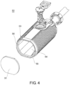
- FIG. 4 is an exploded perspective view showing a small photoelectric sensor 50 of the related art.
- the small photoelectric sensor 50 includes a cover lens 51, an optical component (not shown), and a holder 53.
- the small photoelectric sensor 50 accommodates an optical component inside the holder 53, and is assembled by attaching the cover lens 51 to the holder 53.
- the cover lens 51 is connected to the holder 53 so that it covers an opening 54 of the holder 53.
- the cover lens 51 that is fitted into an edge 56 which defines the opening 54 of the holder 53, and positioned by a fixing part 55 is connected to the holder 53 using laser welding, ultrasonic welding, or the like (hereinafter referred to as "laser welding or the like").
- the optical component is a component of an optical system that projects light or receives light to or from an object to be detected.
- the optical component is constituted by a light projecting unit including a light projecting element and a light projecting lens and a light receiving unit including a light receiving element and a light receiving lens.
- the opening 54 allowing light projected from an optical component to pass therethrough and introducing light reflected from a detection object, a reflection plate, or the like into the holder, the edge 56 that defines the opening 54 and connects the holder 53 and the cover lens 51, and the fixing part 55 for positioning the cover lens 51 are formed on the front surface.
- FIG. 5 is a perspective view showing a state in which the cover lens 51 of the small photoelectric sensor 50 of the related art is attached to the holder 53.
- the fixing part 55 is formed to surround and fix the entire outer circumference of the cover lens 51 when the cover lens 51 is fitted into the fixing part 55.
- the edge 56 is formed to overlap an outer circumferential part of the cover lens 51 when the cover lens 51 is fitted into the fixing part 55 and placed on the edge 56.
- the edge 56 and the cover lens 51 are connected by laser welding or the like, and thus the optical component accommodated in the holder 53 is sealed.
- the edge 56 is provided to surround the opening 54 of the holder 53, and the fixing part 55 is provided to surround the edge 56. Therefore, when the outer shape of the holder 53 is made smaller while maintaining the width of the edge 56, the capacity for accommodating optical components is reduced.
- FIG. 1 is a perspective view showing an exterior of the small photoelectric sensor 1 according to the present embodiment during use.
- the front, back, left, right, up and down are based on those shown in FIGS. 1 and 2 .
- the small photoelectric sensor 1 is a sensor for detecting whether there is an object or the like according to projection or reception of light.
- the housing 2 is made of, for example, a resin or a metal, and has a substantially rectangular parallelepiped shape. Inside the housing 2, an optical component (not shown) and a holder 11 for holding the optical component are accommodated. In addition, on the outer surface of the housing 2, an indicating lamp 5a and an indicating lamp 5b for displaying an operation state of the small photoelectric sensor 1 (hereinafter collectively referred to as "indicating lamps 5") are provided.
- the operation state includes, for example, a power supply state and a detection state of the small photoelectric sensor 1, but any state may be included according to applications of the small photoelectric sensor 1.
- the indicating lamp 5 may include, for example, a light emitting element such as an LED element.
- fixing parts 12 On the front surface of the housing 2, an opening (not shown) for allowing light projected or received to pass therethrough is provided.
- fixing parts 12 four fixing parts 12a, 12b, 12c, and 12d (hereinafter collectively referred to as "fixing parts 12") for fixing the cover lens 15 at four corners, and the like are fitted.
- the small photoelectric sensor 1 emits light from the optical component accommodated in the housing 2 through the cover lens 15, and allows light to enter the optical component through the cover lens 15, and detects whether there is an object or the like.
- FIG. 2 is a perspective view showing an exterior of the internal components 10 excluding the optical component during use.
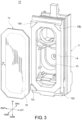
- FIG. 3 is an exploded perspective view showing the internal components 10 excluding the optical component.
- the holder 11 is a component for holding an optical component.
- the holder 11 is formed to include an opening 13, an edge 14, and the fixing part 12.
- the holder 11 may have, for example, a substantially rectangular parallelepiped shape.
- the fact that the holder 11 has a "substantially rectangular parallelepiped shape” may refer to having a shape having a surface other than six surfaces constituting a rectangular parallelepiped shape, a shape with interior angles that are not all 90 degrees, or a shape that is different from a strict rectangular parallelepiped shape.
- a front surface of the holder 11 may have, for example, a substantially rectangular shape.
- the "front surface” is a surface that faces an object to be detected or a reflection plate in the small photoelectric sensor 1 and the internal components 10, and projects and receives light from the front surface.
- the holder 11 is made of a resin, and made of, specifically, PBT, PC, ABS, PMMA, PAR, or the like.
- the holder 11 may be made of a thermoplastic resin, and may be formed by filling a resin into a mold.
- the holder 11 is made of a resin, even if the holder 11 is made smaller so that it is suitable for the small photoelectric sensor 1, it is possible to easily form a fine structure.
- the holder 11 and the cover lens 15 can be connected by laser welding or the like without using an adhesive.
- the fixing part 12 are independently provided at four corners of the front surface of the holder 11 and position the cover lens 15.
- the fixing part 12 may be provided outside a region in which the cover lens 15 and the edge 14 overlap.
- the fixing parts 12 are ribs provided at the four corners of the front surface of the holder 11.
- the "rib” is a component protruding to the front surface with respect to other components such as the edge 14.
- the fixing parts 12 are ribs, the cover lens 15 is fitted and fixed between the ribs. In such a configuration, it is possible to fix the cover lens 15 with a simple configuration without separately providing a component for fixing the cover lens 15 or the like.
- the height of the rib (the length of a part that protrudes from the front surface) may be substantially the same as the thickness of the cover lens 15.
- the height of the rib and the thickness of the cover lens 15 vary, a step is generated, and in a state in which the small photoelectric sensor 1 shown in FIG. 1 is used, dirt is likely to accumulate in the step, and it is difficult to remove dirt adhered to the cover lens 15 due to the step.
- the height of the fixing part 12 and the thickness of the cover lens 15 are set to be substantially the same, it is possible to provide the small photoelectric sensor 1 that is unlikely to become dirty and in which dirt is easily removed.
- the opening 13 is formed on the front surface of the holder 11, and allows light projected from an optical component to pass therethrough, and introduces light such as light reflected from a detection object or a reflection plate and the like into the holder 11.
- the opening 13 may have a polygonal shape, and has an outer shape with a substantially octagonal shape in the present embodiment.
- the opening 13 may have an elliptical shape or a rounded rectangular shape.
- the edge 14 defines the opening 13, and becomes a region connecting the cover lens 15 and the holder 11.
- a width W of the edge 14 is a sealing margin for sealing the holder 11 and the cover lens 15.
- the width W may be constant along the edge 14.
- the optical component (not shown) is a component of an optical system that projects or receives light to or from an object to be detected.
- the optical component is constituted by a light projecting unit including a light projecting element and a light projecting lens and a light receiving unit including a light receiving element and a light receiving lens.
- the optical component is assembled and held in the holder 11.
- the cover lens 15 is, for example, a component such as a plate-like lens.
- the cover lens 15 is provided at a position interposed between four fixing parts 12, and is connected to the edge 14 in a region overlapping the edge 14.
- the cover lens 15 is fixed at four corners with four fixing parts 12, and covers the opening 13 of the holder 11.
- the cover lens 15 is made of a translucent material and can project or receive light from an optical component.
- an outer circumferential part indicated by a dotted line shown in FIG. 3 and a solid line showing an outer edge of the cover lens 15 as an area 16 overlapping the edge 14 is connected to the edge 14 in the overlapping area 16 by laser welding or the like.
- a surface covering the opening 13 of the cover lens 15 may have a shape that substantially matches a shape in which four corners at which the fixing parts 12 are provided are chamfered. That is, the cover lens 15 may have a substantially octagonal shape in which four corners in contact with the four fixing parts 12 are chamfered. In this case, the outer shape of the edge 14 and the outer shape of the cover lens 15 substantially match. In such a configuration, since the outer shape of the space for accommodating optical components can be formed into a polygonal shape, compared to the small photoelectric sensor 50 of the related art having a substantially circular outer shape, rectangular circuit components and substrates can be efficiently accommodated in the holder 11.
- the small photoelectric sensor 1 When the small photoelectric sensor 1 according to the present embodiment includes the four fixing parts 12 independently provided at four corners of the front surface of the holder 11, the edge 14 is not surrounded by the fixing part 12, the edge 14 is provided on the outer circumference of the front surface of the holder 11, and the opening 13 can be widened. Therefore, compared to the small photoelectric sensor 50 of the related art, it is possible to increase a capacity for accommodating optical components (in other words, a volume of a space for accommodating optical components) while maintaining a small outer shape of the small photoelectric sensor 1.
- the opening 13 can be widened while maintaining a constant width W of the edge 14 without being narrowed, it is possible to secure the capacity for accommodating optical components, it is possible to reliably connect the holder 11 and the cover lens 15, and it is possible to secure sealing properties.
Landscapes
- Physics & Mathematics (AREA)
- General Physics & Mathematics (AREA)
- Spectroscopy & Molecular Physics (AREA)
- Engineering & Computer Science (AREA)
- Computer Networks & Wireless Communication (AREA)
- Geophysics (AREA)
- Electromagnetism (AREA)
- General Life Sciences & Earth Sciences (AREA)
- Life Sciences & Earth Sciences (AREA)
- Radar, Positioning & Navigation (AREA)
- Remote Sensing (AREA)
- Optics & Photonics (AREA)
- Photometry And Measurement Of Optical Pulse Characteristics (AREA)
- Geophysics And Detection Of Objects (AREA)
- Switches Operated By Changes In Physical Conditions (AREA)
- Light Receiving Elements (AREA)
- Photovoltaic Devices (AREA)
Claims (3)
- Kleiner photoelektrischer Sensor (1), der Folgendes umfasst:eine Haltevorrichtung (11), in der eine Öffnung (13), eine Kante (14), die die Öffnung (13) definiert, und vier Befestigungsteile (12, 12a, 12b, 12c, 12d), die an vier Ecken einer vorderen Oberfläche der Haltevorrichtung (11) unabhängig voneinander bereitgestellt sind, auf der vorderen Oberfläche bereitgestellt sind, wobei die vier Befestigungsteile (12, 12a, 12b, 12c, 12d) als Rippen bereitgestellt sind, die von der vorderen Oberfläche der Haltevorrichtung (11) vorstehen;eine Abdecklinse (15), die an einer Position zwischen den vier Befestigungsteilen (12, 12a, 12b, 12c, 12d) bereitgestellt ist und in einem Bereich, der mit der Kante (14) überlappt, mit der Kante (14) verbunden ist, wobei eine Höhe jeder der Rippen einer Dicke der Abdecklinse (15) entspricht; undeine optische Komponente, die durch die Haltevorrichtung (11) gehalten wird und durch die Öffnung (13) Licht projiziert oder empfängt,wobei die Haltevorrichtung (11) aus Harz hergestellt ist,und die Haltevorrichtung (11) und die Abdecklinse (15) mittels Laserschweißen ohne Verwenden eines Klebemittels verbunden sind.
- Kleiner photoelektrischer Sensor (1) nach Anspruch 1,
wobei die vier Befestigungsteile (12, 12a, 12b, 12c, 12d) außerhalb eines Bereichs bereitgestellt sind, in dem die Abdecklinse (15) und die Kante (14) überlappen, und wobei vier Ecken der Abdecklinse (15) an den vier Befestigungsteilen (12, 12a, 12b, 12c, 12d) befestigt sind. - Kleiner photoelektrischer Sensor (1) nach Anspruch 1 oder 2,wobei die vordere Oberfläche der Haltevorrichtung (11) eine im Wesentlichen rechteckige Form aufweist undwobei die Abdecklinse (15) eine im Wesentlichen achteckige Form aufweist, in der vier Ecken, die mit den vier Befestigungsteilen (12, 12a, 12b, 12c, 12d) in Kontakt sind, abgeschrägt sind.
Applications Claiming Priority (1)
| Application Number | Priority Date | Filing Date | Title |
|---|---|---|---|
| JP2018047510A JP6991462B2 (ja) | 2018-03-15 | 2018-03-15 | 小型光電センサ |
Publications (2)
| Publication Number | Publication Date |
|---|---|
| EP3540489A1 EP3540489A1 (de) | 2019-09-18 |
| EP3540489B1 true EP3540489B1 (de) | 2024-10-09 |
Family
ID=65433567
Family Applications (1)
| Application Number | Title | Priority Date | Filing Date |
|---|---|---|---|
| EP19156891.4A Active EP3540489B1 (de) | 2018-03-15 | 2019-02-13 | Kleiner fotoelektrischer sensor |
Country Status (4)
| Country | Link |
|---|---|
| US (1) | US11112299B2 (de) |
| EP (1) | EP3540489B1 (de) |
| JP (1) | JP6991462B2 (de) |
| CN (1) | CN110275212B (de) |
Families Citing this family (2)
| Publication number | Priority date | Publication date | Assignee | Title |
|---|---|---|---|---|
| JP7446069B2 (ja) | 2019-09-03 | 2024-03-08 | キヤノン株式会社 | 露光装置及び物品の製造方法 |
| IT202100006377A1 (it) * | 2021-03-17 | 2022-09-17 | Global Building Srl | Dispositivo di rilevamento del movimento relativo di elementi posti in locali filtro-fumo |
Citations (2)
| Publication number | Priority date | Publication date | Assignee | Title |
|---|---|---|---|---|
| US4808812A (en) * | 1986-06-19 | 1989-02-28 | Honda Motor Co., Ltd. | Composite type light sensor having plural sensors with different light receiving angle optical characteristics |
| US20100246370A1 (en) * | 2006-02-01 | 2010-09-30 | Sanyo Electric Co., Ltd. | Optical pickup unit and optical disc apparatus |
Family Cites Families (17)
| Publication number | Priority date | Publication date | Assignee | Title |
|---|---|---|---|---|
| JPH0277831A (ja) | 1988-06-27 | 1990-03-16 | Mitsubishi Electric Corp | プリンタ制御装置 |
| JPH071716Y2 (ja) * | 1988-12-02 | 1995-01-18 | オムロン株式会社 | 光電スイッチ |
| JPH0731478Y2 (ja) * | 1989-09-26 | 1995-07-19 | 松下電工株式会社 | 光電スイッチ |
| JP3177287B2 (ja) | 1991-03-07 | 2001-06-18 | 三洋電機株式会社 | 受光モジュ−ル |
| JP2566878Y2 (ja) * | 1992-03-03 | 1998-03-30 | サンクス 株式会社 | 回帰反射形光電センサ |
| US20070091293A1 (en) * | 2005-10-19 | 2007-04-26 | Omron Corporation | Photoelectric sensor, optical module and method of producing same |
| JP4618507B2 (ja) * | 2005-10-28 | 2011-01-26 | ソニー株式会社 | カメラモジュールおよび電子機器 |
| US7400463B1 (en) * | 2007-03-06 | 2008-07-15 | Tdk Taiwan Corp. | Miniature lens focusing mechanism |
| US7959364B2 (en) * | 2009-05-04 | 2011-06-14 | Tdk Taiwan Corporation | Lens protection structure for miniature lens focusing mechanism |
| JP2013211152A (ja) * | 2012-03-30 | 2013-10-10 | Azbil Corp | 光電センサ |
| JP2013252667A (ja) * | 2012-06-07 | 2013-12-19 | Omron Corp | 樹脂部品、光電センサおよび樹脂部品の製造方法 |
| CN203630370U (zh) | 2013-12-17 | 2014-06-04 | 上海兰宝传感科技股份有限公司 | 零盲区漫反射式光电传感器 |
| JP6381909B2 (ja) * | 2013-12-27 | 2018-08-29 | パナソニック デバイスSunx株式会社 | 変位センサ |
| JP6331829B2 (ja) | 2014-02-23 | 2018-05-30 | オムロン株式会社 | 光電センサ |
| JP2014170758A (ja) | 2014-05-22 | 2014-09-18 | Sharp Corp | 照明装置、および車両用前照灯 |
| JP6447542B2 (ja) * | 2016-03-03 | 2019-01-09 | オムロン株式会社 | センサ機器およびその製造方法 |
| JP6394626B2 (ja) * | 2016-03-03 | 2018-09-26 | オムロン株式会社 | センサ機器 |
-
2018
- 2018-03-15 JP JP2018047510A patent/JP6991462B2/ja active Active
-
2019
- 2019-02-13 EP EP19156891.4A patent/EP3540489B1/de active Active
- 2019-02-13 CN CN201910112177.3A patent/CN110275212B/zh active Active
- 2019-02-14 US US16/275,321 patent/US11112299B2/en active Active
Patent Citations (2)
| Publication number | Priority date | Publication date | Assignee | Title |
|---|---|---|---|---|
| US4808812A (en) * | 1986-06-19 | 1989-02-28 | Honda Motor Co., Ltd. | Composite type light sensor having plural sensors with different light receiving angle optical characteristics |
| US20100246370A1 (en) * | 2006-02-01 | 2010-09-30 | Sanyo Electric Co., Ltd. | Optical pickup unit and optical disc apparatus |
Also Published As
| Publication number | Publication date |
|---|---|
| CN110275212B (zh) | 2021-11-19 |
| JP2019160664A (ja) | 2019-09-19 |
| EP3540489A1 (de) | 2019-09-18 |
| US20190285463A1 (en) | 2019-09-19 |
| US11112299B2 (en) | 2021-09-07 |
| CN110275212A (zh) | 2019-09-24 |
| JP6991462B2 (ja) | 2022-01-12 |
Similar Documents
| Publication | Publication Date | Title |
|---|---|---|
| US10429563B2 (en) | Lamp including light source socket and light guide | |
| KR101935312B1 (ko) | 차량용 도어 미러 | |
| US9121567B2 (en) | Turn lamp for vehicle outside mirror | |
| CN104798213B (zh) | 光传感器单元 | |
| CN109076150B (zh) | 相机模块和车辆 | |
| US20250362388A1 (en) | Limited reflection type sensor | |
| KR20120016430A (ko) | 차량용 카메라 | |
| US10495844B2 (en) | Lens drive device, camera module, and camera-mounting device | |
| JP6381909B2 (ja) | 変位センサ | |
| EP3540489B1 (de) | Kleiner fotoelektrischer sensor | |
| US10237457B2 (en) | Light receiving apparatus having body and exterior portion secured to mount | |
| US20070104478A1 (en) | Monitor camera | |
| CN110275215A (zh) | 光电传感器 | |
| KR20160005414A (ko) | 카메라 모듈 | |
| JP6220672B2 (ja) | 変位センサ | |
| CN109863056B (zh) | 平视显示装置 | |
| JP2009110815A (ja) | 多光軸光電センサ | |
| US10686095B2 (en) | Photoelectric sensor | |
| CN119492024B (zh) | 徽标灯模块,外部后视组件和机动车辆 | |
| CN1763561A (zh) | 光电探测器 | |
| JP7225964B2 (ja) | 遮光部材及びカメラ | |
| KR20250166254A (ko) | 라이다 내장 장착 장치 및 차량(lidar built-in mounting device and vehicle) | |
| JP2019062354A (ja) | 撮像装置 | |
| EP3540472A1 (de) | Photoelektrischer sensor | |
| KR20160064841A (ko) | 카메라용 윈도우 설치 구조체 |
Legal Events
| Date | Code | Title | Description |
|---|---|---|---|
| PUAI | Public reference made under article 153(3) epc to a published international application that has entered the european phase |
Free format text: ORIGINAL CODE: 0009012 |
|
| STAA | Information on the status of an ep patent application or granted ep patent |
Free format text: STATUS: REQUEST FOR EXAMINATION WAS MADE |
|
| 17P | Request for examination filed |
Effective date: 20190213 |
|
| AK | Designated contracting states |
Kind code of ref document: A1 Designated state(s): AL AT BE BG CH CY CZ DE DK EE ES FI FR GB GR HR HU IE IS IT LI LT LU LV MC MK MT NL NO PL PT RO RS SE SI SK SM TR |
|
| AX | Request for extension of the european patent |
Extension state: BA ME |
|
| RBV | Designated contracting states (corrected) |
Designated state(s): AL AT BE BG CH CY CZ DE DK EE ES FI FR GB GR HR HU IE IS IT LI LT LU LV MC MK MT NL NO PL PT RO RS SE SI SK SM TR |
|
| STAA | Information on the status of an ep patent application or granted ep patent |
Free format text: STATUS: EXAMINATION IS IN PROGRESS |
|
| 17Q | First examination report despatched |
Effective date: 20200814 |
|
| GRAP | Despatch of communication of intention to grant a patent |
Free format text: ORIGINAL CODE: EPIDOSNIGR1 |
|
| STAA | Information on the status of an ep patent application or granted ep patent |
Free format text: STATUS: GRANT OF PATENT IS INTENDED |
|
| INTG | Intention to grant announced |
Effective date: 20240516 |
|
| GRAS | Grant fee paid |
Free format text: ORIGINAL CODE: EPIDOSNIGR3 |
|
| GRAA | (expected) grant |
Free format text: ORIGINAL CODE: 0009210 |
|
| STAA | Information on the status of an ep patent application or granted ep patent |
Free format text: STATUS: THE PATENT HAS BEEN GRANTED |
|
| AK | Designated contracting states |
Kind code of ref document: B1 Designated state(s): AL AT BE BG CH CY CZ DE DK EE ES FI FR GB GR HR HU IE IS IT LI LT LU LV MC MK MT NL NO PL PT RO RS SE SI SK SM TR |
|
| REG | Reference to a national code |
Ref country code: CH Ref legal event code: EP |
|
| REG | Reference to a national code |
Ref country code: DE Ref legal event code: R096 Ref document number: 602019059930 Country of ref document: DE |
|
| REG | Reference to a national code |
Ref country code: IE Ref legal event code: FG4D |
|
| REG | Reference to a national code |
Ref country code: LT Ref legal event code: MG9D |
|
| REG | Reference to a national code |
Ref country code: NL Ref legal event code: MP Effective date: 20241009 |
|
| REG | Reference to a national code |
Ref country code: AT Ref legal event code: MK05 Ref document number: 1731177 Country of ref document: AT Kind code of ref document: T Effective date: 20241009 |
|
| PG25 | Lapsed in a contracting state [announced via postgrant information from national office to epo] |
Ref country code: NL Free format text: LAPSE BECAUSE OF FAILURE TO SUBMIT A TRANSLATION OF THE DESCRIPTION OR TO PAY THE FEE WITHIN THE PRESCRIBED TIME-LIMIT Effective date: 20241009 |
|
| PG25 | Lapsed in a contracting state [announced via postgrant information from national office to epo] |
Ref country code: NL Free format text: LAPSE BECAUSE OF FAILURE TO SUBMIT A TRANSLATION OF THE DESCRIPTION OR TO PAY THE FEE WITHIN THE PRESCRIBED TIME-LIMIT Effective date: 20241009 |
|
| PG25 | Lapsed in a contracting state [announced via postgrant information from national office to epo] |
Ref country code: HR Free format text: LAPSE BECAUSE OF FAILURE TO SUBMIT A TRANSLATION OF THE DESCRIPTION OR TO PAY THE FEE WITHIN THE PRESCRIBED TIME-LIMIT Effective date: 20241009 Ref country code: PT Free format text: LAPSE BECAUSE OF FAILURE TO SUBMIT A TRANSLATION OF THE DESCRIPTION OR TO PAY THE FEE WITHIN THE PRESCRIBED TIME-LIMIT Effective date: 20250210 Ref country code: IS Free format text: LAPSE BECAUSE OF FAILURE TO SUBMIT A TRANSLATION OF THE DESCRIPTION OR TO PAY THE FEE WITHIN THE PRESCRIBED TIME-LIMIT Effective date: 20250209 |
|
| PG25 | Lapsed in a contracting state [announced via postgrant information from national office to epo] |
Ref country code: FI Free format text: LAPSE BECAUSE OF FAILURE TO SUBMIT A TRANSLATION OF THE DESCRIPTION OR TO PAY THE FEE WITHIN THE PRESCRIBED TIME-LIMIT Effective date: 20241009 |
|
| PG25 | Lapsed in a contracting state [announced via postgrant information from national office to epo] |
Ref country code: BG Free format text: LAPSE BECAUSE OF FAILURE TO SUBMIT A TRANSLATION OF THE DESCRIPTION OR TO PAY THE FEE WITHIN THE PRESCRIBED TIME-LIMIT Effective date: 20241009 |
|
| PG25 | Lapsed in a contracting state [announced via postgrant information from national office to epo] |
Ref country code: ES Free format text: LAPSE BECAUSE OF FAILURE TO SUBMIT A TRANSLATION OF THE DESCRIPTION OR TO PAY THE FEE WITHIN THE PRESCRIBED TIME-LIMIT Effective date: 20241009 |
|
| PG25 | Lapsed in a contracting state [announced via postgrant information from national office to epo] |
Ref country code: NO Free format text: LAPSE BECAUSE OF FAILURE TO SUBMIT A TRANSLATION OF THE DESCRIPTION OR TO PAY THE FEE WITHIN THE PRESCRIBED TIME-LIMIT Effective date: 20250109 |
|
| PG25 | Lapsed in a contracting state [announced via postgrant information from national office to epo] |
Ref country code: LV Free format text: LAPSE BECAUSE OF FAILURE TO SUBMIT A TRANSLATION OF THE DESCRIPTION OR TO PAY THE FEE WITHIN THE PRESCRIBED TIME-LIMIT Effective date: 20241009 Ref country code: GR Free format text: LAPSE BECAUSE OF FAILURE TO SUBMIT A TRANSLATION OF THE DESCRIPTION OR TO PAY THE FEE WITHIN THE PRESCRIBED TIME-LIMIT Effective date: 20250110 Ref country code: AT Free format text: LAPSE BECAUSE OF FAILURE TO SUBMIT A TRANSLATION OF THE DESCRIPTION OR TO PAY THE FEE WITHIN THE PRESCRIBED TIME-LIMIT Effective date: 20241009 |
|
| PG25 | Lapsed in a contracting state [announced via postgrant information from national office to epo] |
Ref country code: PL Free format text: LAPSE BECAUSE OF FAILURE TO SUBMIT A TRANSLATION OF THE DESCRIPTION OR TO PAY THE FEE WITHIN THE PRESCRIBED TIME-LIMIT Effective date: 20241009 |
|
| PG25 | Lapsed in a contracting state [announced via postgrant information from national office to epo] |
Ref country code: RS Free format text: LAPSE BECAUSE OF FAILURE TO SUBMIT A TRANSLATION OF THE DESCRIPTION OR TO PAY THE FEE WITHIN THE PRESCRIBED TIME-LIMIT Effective date: 20250109 |
|
| PG25 | Lapsed in a contracting state [announced via postgrant information from national office to epo] |
Ref country code: SM Free format text: LAPSE BECAUSE OF FAILURE TO SUBMIT A TRANSLATION OF THE DESCRIPTION OR TO PAY THE FEE WITHIN THE PRESCRIBED TIME-LIMIT Effective date: 20241009 |
|
| PG25 | Lapsed in a contracting state [announced via postgrant information from national office to epo] |
Ref country code: DK Free format text: LAPSE BECAUSE OF FAILURE TO SUBMIT A TRANSLATION OF THE DESCRIPTION OR TO PAY THE FEE WITHIN THE PRESCRIBED TIME-LIMIT Effective date: 20241009 |
|
| REG | Reference to a national code |
Ref country code: DE Ref legal event code: R097 Ref document number: 602019059930 Country of ref document: DE |
|
| PG25 | Lapsed in a contracting state [announced via postgrant information from national office to epo] |
Ref country code: EE Free format text: LAPSE BECAUSE OF FAILURE TO SUBMIT A TRANSLATION OF THE DESCRIPTION OR TO PAY THE FEE WITHIN THE PRESCRIBED TIME-LIMIT Effective date: 20241009 |
|
| PG25 | Lapsed in a contracting state [announced via postgrant information from national office to epo] |
Ref country code: RO Free format text: LAPSE BECAUSE OF FAILURE TO SUBMIT A TRANSLATION OF THE DESCRIPTION OR TO PAY THE FEE WITHIN THE PRESCRIBED TIME-LIMIT Effective date: 20241009 |
|
| PG25 | Lapsed in a contracting state [announced via postgrant information from national office to epo] |
Ref country code: SK Free format text: LAPSE BECAUSE OF FAILURE TO SUBMIT A TRANSLATION OF THE DESCRIPTION OR TO PAY THE FEE WITHIN THE PRESCRIBED TIME-LIMIT Effective date: 20241009 |
|
| PG25 | Lapsed in a contracting state [announced via postgrant information from national office to epo] |
Ref country code: CZ Free format text: LAPSE BECAUSE OF FAILURE TO SUBMIT A TRANSLATION OF THE DESCRIPTION OR TO PAY THE FEE WITHIN THE PRESCRIBED TIME-LIMIT Effective date: 20241009 |
|
| PG25 | Lapsed in a contracting state [announced via postgrant information from national office to epo] |
Ref country code: IT Free format text: LAPSE BECAUSE OF FAILURE TO SUBMIT A TRANSLATION OF THE DESCRIPTION OR TO PAY THE FEE WITHIN THE PRESCRIBED TIME-LIMIT Effective date: 20241009 |
|
| PLBE | No opposition filed within time limit |
Free format text: ORIGINAL CODE: 0009261 |
|
| STAA | Information on the status of an ep patent application or granted ep patent |
Free format text: STATUS: NO OPPOSITION FILED WITHIN TIME LIMIT |
|
| PG25 | Lapsed in a contracting state [announced via postgrant information from national office to epo] |
Ref country code: SE Free format text: LAPSE BECAUSE OF FAILURE TO SUBMIT A TRANSLATION OF THE DESCRIPTION OR TO PAY THE FEE WITHIN THE PRESCRIBED TIME-LIMIT Effective date: 20241009 |
|
| PG25 | Lapsed in a contracting state [announced via postgrant information from national office to epo] |
Ref country code: MC Free format text: LAPSE BECAUSE OF FAILURE TO SUBMIT A TRANSLATION OF THE DESCRIPTION OR TO PAY THE FEE WITHIN THE PRESCRIBED TIME-LIMIT Effective date: 20241009 |
|
| 26N | No opposition filed |
Effective date: 20250710 |
|
| REG | Reference to a national code |
Ref country code: CH Ref legal event code: PL |
|
| PG25 | Lapsed in a contracting state [announced via postgrant information from national office to epo] |
Ref country code: LU Free format text: LAPSE BECAUSE OF NON-PAYMENT OF DUE FEES Effective date: 20250213 |
|
| PG25 | Lapsed in a contracting state [announced via postgrant information from national office to epo] |
Ref country code: CH Free format text: LAPSE BECAUSE OF NON-PAYMENT OF DUE FEES Effective date: 20250228 |
|
| GBPC | Gb: european patent ceased through non-payment of renewal fee |
Effective date: 20250213 |
|
| REG | Reference to a national code |
Ref country code: BE Ref legal event code: MM Effective date: 20250228 |
|
| PG25 | Lapsed in a contracting state [announced via postgrant information from national office to epo] |
Ref country code: GB Free format text: LAPSE BECAUSE OF NON-PAYMENT OF DUE FEES Effective date: 20250213 |
|
| PG25 | Lapsed in a contracting state [announced via postgrant information from national office to epo] |
Ref country code: FR Free format text: LAPSE BECAUSE OF NON-PAYMENT OF DUE FEES Effective date: 20250228 |
|
| PG25 | Lapsed in a contracting state [announced via postgrant information from national office to epo] |
Ref country code: BE Free format text: LAPSE BECAUSE OF NON-PAYMENT OF DUE FEES Effective date: 20250228 |
|
| PG25 | Lapsed in a contracting state [announced via postgrant information from national office to epo] |
Ref country code: IE Free format text: LAPSE BECAUSE OF NON-PAYMENT OF DUE FEES Effective date: 20250213 |
|
| PGFP | Annual fee paid to national office [announced via postgrant information from national office to epo] |
Ref country code: DE Payment date: 20260217 Year of fee payment: 8 |