EP3540458B1 - Optischer sicherheitssensor - Google Patents
Optischer sicherheitssensor Download PDFInfo
- Publication number
- EP3540458B1 EP3540458B1 EP18211234.2A EP18211234A EP3540458B1 EP 3540458 B1 EP3540458 B1 EP 3540458B1 EP 18211234 A EP18211234 A EP 18211234A EP 3540458 B1 EP3540458 B1 EP 3540458B1
- Authority
- EP
- European Patent Office
- Prior art keywords
- light
- receiver
- time
- projector
- light projector
- Prior art date
- Legal status (The legal status is an assumption and is not a legal conclusion. Google has not performed a legal analysis and makes no representation as to the accuracy of the status listed.)
- Active
Links
Images


Classifications
-
- G—PHYSICS
- G01—MEASURING; TESTING
- G01S—RADIO DIRECTION-FINDING; RADIO NAVIGATION; DETERMINING DISTANCE OR VELOCITY BY USE OF RADIO WAVES; LOCATING OR PRESENCE-DETECTING BY USE OF THE REFLECTION OR RERADIATION OF RADIO WAVES; ANALOGOUS ARRANGEMENTS USING OTHER WAVES
- G01S5/00—Position-fixing by co-ordinating two or more direction or position line determinations; Position-fixing by co-ordinating two or more distance determinations
- G01S5/18—Position-fixing by co-ordinating two or more direction or position line determinations; Position-fixing by co-ordinating two or more distance determinations using ultrasonic, sonic or infrasonic waves
- G01S5/30—Determining absolute distances from a plurality of spaced points of known location
-
- G—PHYSICS
- G01—MEASURING; TESTING
- G01B—MEASURING LENGTH, THICKNESS OR SIMILAR LINEAR DIMENSIONS; MEASURING ANGLES; MEASURING AREAS; MEASURING IRREGULARITIES OF SURFACES OR CONTOURS
- G01B11/00—Measuring arrangements characterised by the use of optical techniques
- G01B11/02—Measuring arrangements characterised by the use of optical techniques for measuring length, width or thickness
- G01B11/026—Measuring arrangements characterised by the use of optical techniques for measuring length, width or thickness by measuring distance between sensor and object
-
- G—PHYSICS
- G01—MEASURING; TESTING
- G01C—MEASURING DISTANCES, LEVELS OR BEARINGS; SURVEYING; NAVIGATION; GYROSCOPIC INSTRUMENTS; PHOTOGRAMMETRY OR VIDEOGRAMMETRY
- G01C3/00—Measuring distances in line of sight; Optical rangefinders
- G01C3/02—Details
- G01C3/06—Use of electric means to obtain final indication
- G01C3/08—Use of electric radiation detectors
-
- G—PHYSICS
- G01—MEASURING; TESTING
- G01D—MEASURING NOT SPECIALLY ADAPTED FOR A SPECIFIC VARIABLE; ARRANGEMENTS FOR MEASURING TWO OR MORE VARIABLES NOT COVERED IN A SINGLE OTHER SUBCLASS; TARIFF METERING APPARATUS; MEASURING OR TESTING NOT OTHERWISE PROVIDED FOR
- G01D5/00—Mechanical means for transferring the output of a sensing member; Means for converting the output of a sensing member to another variable where the form or nature of the sensing member does not constrain the means for converting; Transducers not specially adapted for a specific variable
- G01D5/26—Mechanical means for transferring the output of a sensing member; Means for converting the output of a sensing member to another variable where the form or nature of the sensing member does not constrain the means for converting; Transducers not specially adapted for a specific variable characterised by optical transfer means, i.e. using infrared, visible, or ultraviolet light
- G01D5/28—Mechanical means for transferring the output of a sensing member; Means for converting the output of a sensing member to another variable where the form or nature of the sensing member does not constrain the means for converting; Transducers not specially adapted for a specific variable characterised by optical transfer means, i.e. using infrared, visible, or ultraviolet light with deflection of beams of light, e.g. for direct optical indication
-
- G—PHYSICS
- G01—MEASURING; TESTING
- G01S—RADIO DIRECTION-FINDING; RADIO NAVIGATION; DETERMINING DISTANCE OR VELOCITY BY USE OF RADIO WAVES; LOCATING OR PRESENCE-DETECTING BY USE OF THE REFLECTION OR RERADIATION OF RADIO WAVES; ANALOGOUS ARRANGEMENTS USING OTHER WAVES
- G01S17/00—Systems using the reflection or reradiation of electromagnetic waves other than radio waves, e.g. lidar systems
- G01S17/02—Systems using the reflection of electromagnetic waves other than radio waves
- G01S17/06—Systems determining position data of a target
- G01S17/08—Systems determining position data of a target for measuring distance only
-
- G—PHYSICS
- G01—MEASURING; TESTING
- G01S—RADIO DIRECTION-FINDING; RADIO NAVIGATION; DETERMINING DISTANCE OR VELOCITY BY USE OF RADIO WAVES; LOCATING OR PRESENCE-DETECTING BY USE OF THE REFLECTION OR RERADIATION OF RADIO WAVES; ANALOGOUS ARRANGEMENTS USING OTHER WAVES
- G01S17/00—Systems using the reflection or reradiation of electromagnetic waves other than radio waves, e.g. lidar systems
- G01S17/02—Systems using the reflection of electromagnetic waves other than radio waves
- G01S17/06—Systems determining position data of a target
- G01S17/08—Systems determining position data of a target for measuring distance only
- G01S17/10—Systems determining position data of a target for measuring distance only using transmission of interrupted, pulse-modulated waves
-
- G—PHYSICS
- G01—MEASURING; TESTING
- G01S—RADIO DIRECTION-FINDING; RADIO NAVIGATION; DETERMINING DISTANCE OR VELOCITY BY USE OF RADIO WAVES; LOCATING OR PRESENCE-DETECTING BY USE OF THE REFLECTION OR RERADIATION OF RADIO WAVES; ANALOGOUS ARRANGEMENTS USING OTHER WAVES
- G01S17/00—Systems using the reflection or reradiation of electromagnetic waves other than radio waves, e.g. lidar systems
- G01S17/87—Combinations of systems using electromagnetic waves other than radio waves
-
- G—PHYSICS
- G01—MEASURING; TESTING
- G01S—RADIO DIRECTION-FINDING; RADIO NAVIGATION; DETERMINING DISTANCE OR VELOCITY BY USE OF RADIO WAVES; LOCATING OR PRESENCE-DETECTING BY USE OF THE REFLECTION OR RERADIATION OF RADIO WAVES; ANALOGOUS ARRANGEMENTS USING OTHER WAVES
- G01S17/00—Systems using the reflection or reradiation of electromagnetic waves other than radio waves, e.g. lidar systems
- G01S17/88—Lidar systems specially adapted for specific applications
-
- G—PHYSICS
- G01—MEASURING; TESTING
- G01S—RADIO DIRECTION-FINDING; RADIO NAVIGATION; DETERMINING DISTANCE OR VELOCITY BY USE OF RADIO WAVES; LOCATING OR PRESENCE-DETECTING BY USE OF THE REFLECTION OR RERADIATION OF RADIO WAVES; ANALOGOUS ARRANGEMENTS USING OTHER WAVES
- G01S7/00—Details of systems according to groups G01S13/00, G01S15/00, G01S17/00
- G01S7/48—Details of systems according to groups G01S13/00, G01S15/00, G01S17/00 of systems according to group G01S17/00
- G01S7/481—Constructional features, e.g. arrangements of optical elements
- G01S7/4814—Constructional features, e.g. arrangements of optical elements of transmitters alone
- G01S7/4815—Constructional features, e.g. arrangements of optical elements of transmitters alone using multiple transmitters
-
- G—PHYSICS
- G01—MEASURING; TESTING
- G01S—RADIO DIRECTION-FINDING; RADIO NAVIGATION; DETERMINING DISTANCE OR VELOCITY BY USE OF RADIO WAVES; LOCATING OR PRESENCE-DETECTING BY USE OF THE REFLECTION OR RERADIATION OF RADIO WAVES; ANALOGOUS ARRANGEMENTS USING OTHER WAVES
- G01S7/00—Details of systems according to groups G01S13/00, G01S15/00, G01S17/00
- G01S7/48—Details of systems according to groups G01S13/00, G01S15/00, G01S17/00 of systems according to group G01S17/00
- G01S7/497—Means for monitoring or calibrating
-
- G—PHYSICS
- G08—SIGNALLING
- G08B—SIGNALLING SYSTEMS, e.g. PERSONAL CALLING SYSTEMS; ORDER TELEGRAPHS; ALARM SYSTEMS
- G08B15/00—Identifying, scaring or incapacitating burglars, thieves or intruders, e.g. by explosives
-
- F—MECHANICAL ENGINEERING; LIGHTING; HEATING; WEAPONS; BLASTING
- F16—ENGINEERING ELEMENTS AND UNITS; GENERAL MEASURES FOR PRODUCING AND MAINTAINING EFFECTIVE FUNCTIONING OF MACHINES OR INSTALLATIONS; THERMAL INSULATION IN GENERAL
- F16P—SAFETY DEVICES IN GENERAL; SAFETY DEVICES FOR PRESSES
- F16P3/00—Safety devices acting in conjunction with the control or operation of a machine; Control arrangements requiring the simultaneous use of two or more parts of the body
- F16P3/12—Safety devices acting in conjunction with the control or operation of a machine; Control arrangements requiring the simultaneous use of two or more parts of the body with means, e.g. feelers, which in case of the presence of a body part of a person in or near the danger zone influence the control or operation of the machine
- F16P3/14—Safety devices acting in conjunction with the control or operation of a machine; Control arrangements requiring the simultaneous use of two or more parts of the body with means, e.g. feelers, which in case of the presence of a body part of a person in or near the danger zone influence the control or operation of the machine the means being photocells or other devices sensitive without mechanical contact
-
- F—MECHANICAL ENGINEERING; LIGHTING; HEATING; WEAPONS; BLASTING
- F16—ENGINEERING ELEMENTS AND UNITS; GENERAL MEASURES FOR PRODUCING AND MAINTAINING EFFECTIVE FUNCTIONING OF MACHINES OR INSTALLATIONS; THERMAL INSULATION IN GENERAL
- F16P—SAFETY DEVICES IN GENERAL; SAFETY DEVICES FOR PRESSES
- F16P3/00—Safety devices acting in conjunction with the control or operation of a machine; Control arrangements requiring the simultaneous use of two or more parts of the body
- F16P3/12—Safety devices acting in conjunction with the control or operation of a machine; Control arrangements requiring the simultaneous use of two or more parts of the body with means, e.g. feelers, which in case of the presence of a body part of a person in or near the danger zone influence the control or operation of the machine
- F16P3/14—Safety devices acting in conjunction with the control or operation of a machine; Control arrangements requiring the simultaneous use of two or more parts of the body with means, e.g. feelers, which in case of the presence of a body part of a person in or near the danger zone influence the control or operation of the machine the means being photocells or other devices sensitive without mechanical contact
- F16P3/144—Safety devices acting in conjunction with the control or operation of a machine; Control arrangements requiring the simultaneous use of two or more parts of the body with means, e.g. feelers, which in case of the presence of a body part of a person in or near the danger zone influence the control or operation of the machine the means being photocells or other devices sensitive without mechanical contact using light grids
Definitions
- the disclosure relates to an optical safety sensor that measures distances to an object by using a TOF (Time of Flight) method and detects intrusion of the object to a monitoring area from changes of the distances.
- TOF Time of Flight
- a sensor which uses the TOF method in which time taken from projecting light until receiving reflected light of the projected light is used to measure the distance to the object reflecting the light.
- an optical safety sensor which uses the TOF method to detect the intrusion of an object to monitoring areas from changes of the distance measurement results (for example, European Laid-Open No. 2315052B ).
- a configuration to set a test target is necessary. For example, in prior literature 1 ( United States Laid-Open No.
- EP 2 487 504 A1 discloses a method and apparatus for depth image acquisition of an object wherein at least two time-of-flight cameras are provided and the object is illuminated with a plurality of different light emission states by emitting light signals from each camera. Measurements of the light reflected by the object during each light emission state are obtained at all the cameras wherein the measurements may then be used to optimize the depth images at each of the cameras.
- US 8 224 032 B2 discloses an apparatus for monitoring a spatial area for safeguarding a hazardous area of an automatically operated installation, comprising an illumination device which at least temporarily emits light signals into the spatial area.
- a first image recording unit records a first image of the spatial area.
- the first image recording unit comprises an image sensor having a plurality of pixels.
- An evaluation unit determines a distance value for at least one spatial area point, which is located in the spatial area and is imaged on at least one pixel, by means of a propagation type measurement.
- the propagation type measurement suffers from a limited unambiguity range. Therefore, a test device is designed to check the distance value by means of a reference distance value determined from a second image of said spatial area.
- US 2002/003617 A1 discloses a spatially resolving range-finding system, comprising an object illuminated in a pixel-wise fashion by illuminating beams emanating from light sources, imaging beams striking receiving elements.
- the arrangement of the light sources and the receiving elements is corresponding, and the pixel access in the solid state image sensor is optional.
- the standard light transmitter and the standard light receiver are configurations dedicated to self-test and are not used to monitor the monitoring areas, which is a cause of high cost.
- a configuration is considered in which the standard light transmitter and the standard light receiver dedicated to self-test are not used and optical safety sensors which monitor the monitoring areas are simply duplexed. According to this configuration, it is possible to continue monitoring even if any one of the sensors fails, but there is a problem that particular abnormality locations cannot be specified when an abnormality occurs.
- One aspect of the disclosure is made in view of problems described above and aims to inexpensively implement the optical safety sensor.
- an optical safety sensor includes: a group consisting of a plurality of light projectors/receivers, which is provided with light projecting portions projecting light to a monitoring area and light receiving portions receiving reflected light from the monitoring area; a plurality of distance measurement portions, which measures distances to a subject within the monitoring area using time required from the light projecting to the light receiving; and a plurality of detection portions, which detects, based on measurement results obtained by the distance measurement portions, a malfunction of any one of the light projectors/receivers (abnormality) occurring in any one of the plurality of light projectors/receivers; wherein one of the light projectors/receivers forms one set with a corresponding one of the distance measurement portions and a corresponding one of the detection portions, and each of the light receiving portions provided in the plurality of light projectors/receivers receives the reflected light caused by the light projected from the light projecting portions of all the plurality of light projectors/re
- the optical safety sensor measures the distances to the subject within the monitoring area by the plurality of light projectors/receivers, so that even if a malfunction is generated in any one of the light projectors/receivers, normal monitoring can also be continued.
- the optical safety sensor measures the distances to the subject within the monitoring area by the plurality of light projectors/receivers, so that even if a malfunction is generated in any one of the light projectors/receivers, normal monitoring can also be continued.
- distance measurement results obtained by each light projector/receiver an occasion when the malfunction is generated in any one of the light projectors/receivers can be detected.
- commercial modules operating in a TOF method can be used as the light projectors/receivers, compared with the configuration recited in patent literature 1 that uses standard light projectors and standard light receivers dedicated to self-test, the optical safety sensor can be inexpensively implemented.
- the projected light from one light projector/receiver can be received in another light projector/receiver, so that the light projecting portion and the light receiving portion of each light projector/receiver are diagnosed to specify the abnormality location when the malfunction occurs.
- the optical safety sensor may be that more than one group consisting of a plurality of light projectors/receivers, which is different from the group consisting of the plurality of light projectors/receivers, is further included, and the monitoring areas which are targets of each of the groups are different; the distance measurement portions switch each of the groups in turn to measure the distances, and the detection portions can switch each group in turn to detect the abnormality.
- the distance measurement and abnormality diagnosis can be carried out by one distance measurement portion and one detection portion. Therefore, by sharing the distance measurement portions and the detection portions, a wider area can be safely monitored while suppressing equipment cost at a low level.
- the detection portions determine that the malfunction (abnormality) of any one of the light projectors/receivers occurs in any one of the first light projector/receiver and the second light projector/receiver.
- the optical safety sensor it is configured that when the measured distance based on the time from the light projecting by the light projecting portion of the first light projector/receiver to the light receiving by the light receiving portion of the first light projector/receiver does not match with the measured distance based on the time from the light projecting by the light projecting portion of the second light projector/receiver to the light receiving by the light receiving portion of the first light projector/receiver, the detection portions determine that the abnormality occurs in any one of the light projecting portion of the first light projector/receiver and the light projecting portion of the second light projector/receiver.
- whether the abnormality occurs in at least any one of the light projecting portion of the first light projector/receiver and the light projecting portion of the second light projector/receiver can be determined by comparing the measured distances based on the time until specific light receiving portions receive light projected respectively by the plurality of mutually different light projecting portions.
- the presence or absence of abnormality in the light projecting portion of the first light projector/receiver and the presence or absence of abnormality in the light projecting portion of the second light projector/receiver can be determined separately using the difference between the measured distances based on the time from each of the two times of light projecting with a time interval to the light receiving.
- the detection portions determine that the abnormality occurs in any one of the light receiving portion of the first light projector/receiver and the light receiving portion of the second light projector/receiver.
- whether the abnormality occurs in at least any one of the light receiving portion of the first light projector/receiver and the light receiving portion of the second light projector/receiver can be determined by comparing the measured distances based on the time for the projected light of the specific light projecting portions being received by each of the plurality of mutually different light receiving portions.
- the presence or absence of abnormality in the light receiving portion of the first light projector/receiver and the presence or absence of abnormality in the light receiving portion of the second light projector/receiver can be determined separately using the difference between the measured distances based on the time from each of the two times of light projecting with a time interval to the light receiving.
- the optical safety sensor when a detection result in one of the detection portions which forms one set with the first light projector/receiver and a detection result in another one of the detection portions which forms one set with the second light projector/receiver are compared with one another, and detection results are different from one another, an error may be output.
- the detection result of the first light projector/receiver and the detection result of the second light projector/receiver can be compared with one another.
- the detection results are different from one another, it is considered that the abnormality occurs in at least any one of the detection results, so that the error is output on such an occasion, by which the presence or absence of abnormality can be determined with higher accuracy.
- the optical safety sensor can be inexpensively implemented.
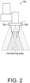
- FIG. 2 schematically illustrates one example of an application case of an optical safety sensor 1 of the embodiment.
- the optical safety sensor 1 of the embodiment is used to set regions containing work ranges where a robot arm 100 works as monitoring areas and to prevent a user who intrudes the monitoring areas from colliding with the robot arm 100.
- the optical safety sensor 1 monitors the regions including the work range of the robot arm 100 as the monitoring area. If the optical safety sensor 1 detects that an object intrudes into the monitoring area from a change of distance measured using the TOF method, a detection result is transmitted to the robot arm 100. If the robot arm 100 receives the detection result from the optical safety sensor 1, movement of the object itself is slowed down or stopped so that the object does not collide.
- the optical safety sensor 1 includes at least two light projectors/receivers that project light to the same monitoring area and receive reflected light from the monitoring area.
- the optical safety sensor 1 determines whether there is an abnormality based on distances to the monitoring area which are calculated respectively by a first light projector/receiver 20A and a second light projector/receiver 20B of the at least two light projectors/receivers.
- the optical safety sensor 1 diagnoses abnormality contents.
- the optical safety sensor 1 executes the next light projecting from at least any one of the first light projector/receiver 20A and the second light projector/receiver 20B after a fixed period of time elapsed, and specifies an abnormality location based on the distance to the monitoring area measured from this next light projecting and light receiving of the reflected light thereof.
- the optical safety sensor 1 transmits a diagnosis result to the robot arm 100, and the robot arm 100 performs operations corresponding to the diagnosis results.
- the specified abnormality location of the optical safety sensor 1 may be output using an output device such as an operation panel of the robot arm 100, or the like.
- the optical safety sensor 1 can use the at least two light projectors/receivers to measure the distance to the monitoring area and the object intruding the monitoring area in the TOF method. Besides, in the optical safety sensor 1, light projecting and light receiving can be executed dividedly between the first light projector/receiver 20A and the second light projector/receiver 20B. In this way, for example, whether there is an abnormality in the light projecting and the light receiving in each light projector/receiver can be checked, and when an abnormality occurs, the location where the abnormality occurs can be specified.
- the optical safety sensor 1 can be inexpensively implemented. Therefore, the inexpensive optical safety sensor 1 with high security which suppresses the occurrence of abnormality in the monitoring to the monitoring area caused by the abnormality of the light projectors/receivers can be implemented.
- FIG. 1 FIG. 3-FIG. 7 .
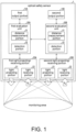
- FIG. 1 is a block diagram showing one example of a main part configuration of the optical safety sensor 1.
- the optical safety sensor 1 includes a first output portion 10A, a second output portion 10B, the first light projector/receiver 20A, the second light projector/receiver 20B, a first evaluation unit 30A, and a second evaluation unit 30B.
- the first light projector/receiver 20A and the second light projector/receiver 20B include identical light projecting portions 21 and light receiving portions 22, and the first evaluation unit 30A and the second evaluation unit 30B include identical distance measurement portions 31 and detection portions 32.
- one light projector/receiver forms one set with the corresponding evaluation unit and output portion.
- the first light projector/receiver 20A forms one set with the first evaluation unit 30A and the first output portion 10A
- the second light projector/receiver 20B forms one set with the second evaluation unit 30B and the second output portion 10B.
- the optical safety sensor 1 can activate the first light projector/receiver 20A and the second light projector/receiver 20B according to instructions of the first evaluation unit 30A and the second evaluation unit 30B.
- the optical safety sensor 1 is, for example, mounted to the robot arm 100 as one portion of the robot arm 100 shown in FIG. 2 to operate.
- the first output portion 10A outputs information received from the first evaluation unit 30A
- the second output portion 10B outputs information received from the second evaluation unit 30B.
- the first output portion 10A obtains, from the first evaluation unit 30A, a diagnosis result of an abnormality diagnosis which is carried out by the first evaluation unit 30A to at least any one of the first light projector/receiver 20A and the second light projector/receiver 20B, and outputs the diagnosis result to the outside.
- the first output portion 10A and the second output portion 10B may be indicators which notify contents of the information received from each evaluation unit by flashing of LEDs or the like.
- the first light projector/receiver 20A and the second light projector/receiver 20B are modules which operate according to the instructions of the first evaluation unit 30A and the second evaluation unit 30B. Particularly, light is projected from the light projecting portions 21 to the monitoring area, and the reflected light reflected in the monitoring area is received by the light receiving portions 22.
- the first light projector/receiver 20A and the second light projector/receiver 20B transmit the information related to light projecting and light receiving carried out by themselves to the first evaluation unit 30A and the second evaluation unit 30B.
- the first light projector/receiver 20A and the second light projector/receiver 20B have a configuration including the identical light projecting portions 21 and light receiving portions 22, but they can also have a configuration including mutually different light projecting portions and light receiving portions.
- the light which is projected by the first light projector/receiver 20A to the monitoring area using the light projecting portion 21 is set as T A
- the reflected light which is received by the first light projector/receiver 20A from the monitoring area using the light receiving portion 22 is set as R A
- the light which is projected by the second light projector/receiver 20B to the monitoring area using the light projecting portion 21 is set as T B
- the reflected light which is received by the second light projector/receiver 20B from monitoring area using the light receiving portion 22 is set as R B .
- reflected light of T B may be included in R A
- similarly reflected light of T A may be included in R B .
- the first evaluation unit 30A and the second evaluation unit 30B integrally control each portion of the optical safety sensor 1.
- Each of the first evaluation unit 30A and the second evaluation unit 30B uses the distance measurement portion 31 to calculate (measure) measured distance from the optical safety sensor 1 to the monitoring area from data obtained by activating the first light projector/receiver 20A and the second light projector/receiver 20Bmeasured distance. Then, the abnormality diagnosis by the detection portion 32 is carried out based on measurement results.
- the first evaluation unit 30A and the second evaluation unit 30B can transmit and receive information when necessary.
- the first evaluation unit 30A may obtain information related to the light receiving of the second light projector/receiver 20B from the second evaluation unit 30B.
- the second evaluation unit 30B may obtain information related to the light projecting of the first light projector/receiver 20A from the first evaluation unit 30A.
- the first evaluation unit 30A and the second evaluation unit 30B mutually compare a detection result (a diagnosis result) of the detection portion 32 that forms one set with the first light projector/receiver 20A with a detection result of the detection portion 32that forms one set with the second light projector/receiver 20B. That is, the first evaluation unit 30A and the second evaluation unit 30B carry out the same abnormality diagnosis to one combination of the light projecting and the light receiving and compare the diagnosis results, thereby determine whether there is a failure in the evaluation units. If the diagnosis results are the same in the mutual comparison, the first evaluation unit 30A and the second evaluation unit 30B transmit and output the diagnosis results to each of the first output portion 10A and the second output portion 10B. On the other hand, when the diagnosis results are different from one another, an error is transmitted and output to each of the first output portion 10A and the second output portion 10B.
- the distance measurement portions 31 measure distances to a subject within the monitoring area using time required from the light projecting to the light receiving. Particularly, if the distance measurement portions 31 receive the information related to the light projecting and the light receiving from at least any one of the first light projector/receiver 20A and the second light projector/receiver 20B, the distance measurement portions 31 calculate the measured distances from the optical safety sensor 1 to the monitoring area using the received information. Furthermore, the distance measurement portions 31 can also receive information related to light projecting and light receiving via an evaluation unit different from the evaluation unit including the distance measurement portions 31 themselves.
- the distance measurement portions 31 use a time t which is from a starting time of light projecting of the light T A to a starting time of light receiving of the reflected light R A and a light speed c to calculate a distance S from the optical safety sensor 1 to the monitoring area.
- the distance measurement portion 31 of the first evaluation unit 30A and the distance measurement portion 31 of the first evaluation unit 30B calculate measured distance respectively for one combination of light projecting and light receiving. Then, the distance measurement portion 31 of the first evaluation unit 30A transmits the calculated distance to the detection portion 32 of the first evaluation unit 30A, and the distance measurement portion 31 of the first evaluation unit 30B transmits the calculated distance to the detection portion 32 of the second evaluation unit 30B.
- the detection portions 32 detect, based on the measurement results of the distance measurement portions 31, the abnormality occurs in the first light projector/receiver 20A or the second light projector/receiver 20B. More particularly, the detection portions 32 compare plural distances which are measured by the distance measurement portions 31 under various combinations of the light projecting portion 21 and the light receiving portion 22 which are included in the first light projector/receiver 20A and the light projecting portion 21 and the light receiving portion 22 which are included in the second light projector/receiver 20B, and detect the abnormality. Furthermore, the comparison of the plural distances are carried out respectively by both of the detection portion 32 of the first evaluation unit 30A and the detection portion 32 of the second evaluation unit 30B.
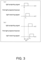
- FIG. 3 is a time chart showing one example of control of the light projecting which is carried out by the first light projector/receiver 20A at the time of the abnormality diagnosis in the optical safety sensor 1.
- the first light projector/receiver 20A uses the light receiving portion 22 to receive the reflected light of the projected light and detects the reflected light as a light receiving signal.
- ⁇ T is preferably a very small value with respect to the flight time of the light, for example, several nanoseconds.
- the detection portions 32 of the optical safety sensor 1 determine whether a difference between the distance S1 and the distance S2 is equal to a distance difference ⁇ S based on the time ⁇ T, and if it is equal, a determination is made that no abnormality occur in any one of the light projecting portion 21 and the light receiving portion 22 of the first light projector/receiver 20A. That is, when the abnormality occurs in any one of the light projecting portion 21 and the light receiving portion 22 of the first light projector/receiver 20A, the detection portion 32 makes a determination according to the fact that due to the abnormality the difference between the distance S 1 and the distance S 2 does not match with a theoretical distance difference ⁇ S based on the time ⁇ T.
- the light projecting portion 21 and the light receiving portion 22 of the first light projector/receiver 20A are used, and it is evident that the light projecting portion 21 and the light receiving portion 22 can be combined in any manner.
- the optical safety sensor 1 applies the above-described method to some combinations related to the light projecting portion 21 and the light receiving portion 22, and specifies a location where the abnormality occurs.
- FIG. 4 is a flowchart showing one example of the flow of the diagnosis processing which is executed by the optical safety sensor 1.
- the first evaluation unit 30A instructs the first light projector/receiver 20A to project light.
- the first light projector/receiver 20A which accepts the instruction uses the light projecting portion 21 to project the light T A to the monitoring area, and receives the reflected light R A of the projected light by the light receiving portion 22.
- the first light projector/receiver 20A transmits data which includes the starting time of the light projecting and the starting time of the light receiving to the distance measurement portion 31 of the first evaluation unit 30A.
- the distance measurement portion 31 calculates the distance R A (T A ) using the time required by the first light projector/receiver 20A from the starting of the light projecting to the light receiving (S1). The distance measurement portion 31 transmits the calculated distance R A (T A ) to the detection portion 32.
- the second evaluation unit 30B instructs the second light projector/receiver 20B to project light.
- the second light projector/receiver 20B which accepts the instruction uses the light projecting portion 21 to project the light T B to the monitoring area, and receives the reflected light R B of the projected light by the light receiving portion 22.
- the second light projector/receiver 20B transmits data which includes the starting time of the light projecting and the starting time of the light receiving to the distance measurement portion 31 of the second evaluation unit 30B.
- the distance measurement portion 31 calculates the distance R B (T B ) using the time required by the second light projector/receiver 20B from the starting of the light projecting to the light receiving (S2). The distance measurement portion 31 transmits the calculated distance R B (T B ) to the detection portion 32.
- the detection portions 32 of the first evaluation unit 30A and the second evaluation unit 30B determine whether the distance R A (T A ) calculated by the distance measurement portion 31 of the first evaluation unit 30A is equal to the distance R B (T B ) calculated by the distance measurement portion 31 of the second evaluation unit 30B (S3). If it is determined to be equal (“YES" in S3), the detection portions 32 determine that the monitoring to the monitoring area has no problem. Then, the optical safety sensor 1 ends the series of processing.
- the detection portions 32 of the first evaluation unit 30A and the second evaluation unit 30B output an error (S4). Then, the optical safety sensor 1 executes an abnormality diagnosis processing described later (S5). After the abnormality diagnosis process is executed, the optical safety sensor 1 ends the series of processing.
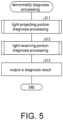
- FIG. 5 is a flowchart showing one example of the flow of the abnormality diagnosis processing executed by the optical safety sensor 1.
- the optical safety sensor 1 executes a light projecting portion diagnosis processing described later, and diagnoses whether an abnormality occurs in the light projecting portions 21 provided respectively on the first light projector/receiver 20A and the second light projector/receiver 20B (S11).
- the optical safety sensor 1 executes a light receiving portion diagnosis processing described later, and diagnoses whether an abnormality occurs in the light receiving portions 22 provided respectively on the first light projector/receiver 20A and the second light projector/receiver 20B (S12).
- the detection portions 32 of the first evaluation unit 30A and the second evaluation unit 30B summarize the diagnosis results in each of the light projecting portion diagnosis processing (S11) and the light receiving portion diagnosis processing (S12). After that, the detection portions 32 output the summarized results to the first output portion 10A and the second output portion 10B (S13). After that, the processing transits to a caller of the abnormality diagnosis processing.
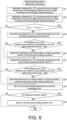
- FIG. 6 is a flowchart showing one example of the flow of the light projecting portion diagnosis processing executed by the optical safety sensor 1.
- the first light projector/receiver 20A which accepts the light projecting instruction from the first evaluation unit 30A, projects the light T A and receives the reflected light R A of the projected light.
- the first light projector/receiver 20A transmits the data which includes the starting time of the light projecting and the starting time of the light receiving to the distance measurement portion 31 of the first evaluation unit 30A.
- the distance measurement portion 31 of the first evaluation unit 30A calculates the measured distance R A (T A ) based on the time taken by the first light projector/receiver 20A from the starting of the light projecting to the light receiving (S21).
- the second evaluation unit 30B instructs the second light projector/receiver 20B to project light.
- the second light projector/receiver 20B which accepts the instruction projects the light T B to the monitoring area.
- the first light projector/receiver 20A receives the reflected light R A by the light receiving portion 22.
- the distance measurement portion 31 of the first evaluation unit 30A acquires the starting time of the light projecting from the second light projector/receiver 20B via the second evaluation unit 30B, and acquires the starting time of the light receiving from the first light projector/receiver 20A.
- the distance measurement portion 31 of the first evaluation unit 30A calculates the measured distance R A (T B ) based on the time from the light projecting of the light T B by the light projecting portion 21 of the second light projector/receiver 20B to the light receiving of the reflected light R A by the light receiving portion 22 of the first light projector/receiver 20A (S22).
- the detection portion 32 of the first evaluation unit 30A determines whether the distance R A (T A ) calculated in S21 matches with the distance R A (T B ) calculated in S22 (S23). If it is determined to be matched (“YES" in S23), the detection portion 32 determines that no abnormality occurs in the light projecting portion 21 of the first light projector/receiver 20A and the light projecting portion 21 of the second light projector/receiver 20B. Then, the processing proceeds to S30.
- the first light projector/receiver 20A which accepts the instruction projects the light T A to the monitoring area. Then, the first light projector/receiver 20A receives the reflected light R A by the light receiving portion 22.
- the detection portion 32 of the first evaluation unit 30A determines whether the difference R A ( ⁇ T) between the distance R A (T A ) calculated in S21 and the measured distance R A (T A ) calculated using the light projecting after time ⁇ T matches with the distance difference ⁇ S based on time ⁇ T (S25).
- the calculation of the R A ( ⁇ T) is carried out by the method described using FIG. 3 . If it is determined that the R A ( ⁇ T) matches with the ⁇ S ("YES" in S25), the detection portion 32 determines that no abnormality occurs in the light projecting portion 21 of the first light projector/receiver 20A, and the processing proceeds to S27.
- the detection portion 32 determines that the abnormality occurs in the light projecting portion 21 of the first light projector/receiver 20A (S26). After that, the processing proceeds to S27.
- the first light projector/receiver 20B which accepts the instruction projects the light T B to the monitoring area. Then, the first light projector/receiver 20A receives the reflected light R A by the light receiving portion 22.
- the distance measurement portion 31 of the first evaluation unit 30A calculates the measured distance R A (T B ) based on the time from the second light projector/receiver 20B starting the light projecting after time ⁇ T to the first light projector/receiver 20A receiving the light (S27).
- the detection portion 32 of the first evaluation unit 30A determines whether the difference R A ( ⁇ T) between the distance R A (T B ) calculated in S22 and the measured distance R A (T B ) based on the time from the light projecting after time ⁇ T to the light receiving matches with the distance difference ⁇ S based on the time ⁇ T (S28). If it is determined that the R A ( ⁇ T) matches with the ⁇ S ("YES" in S28 ), the detection portion 32 determines that no abnormality occurs in the light projecting portion 21 of the second light projector/receiver 20B. After that, the optical safety sensor 1 ends the light projecting portion diagnosis processing, and transits to the caller of the light projecting portion diagnosis processing with the diagnosis results up to the moment.
- the detection portion 32 determines that the abnormality occurs in the light projecting portion 21 of the second light projector/receiver 20B (S29). After that, the processing proceeds to S30.
- the second evaluation unit 30B executes a processing similar to contents executed by the first evaluation unit 30A in S21-S29, and carries out abnormality diagnosis for the light projecting portion 21 of the first light projector/receiver 20A and the light projecting portion 21 of the second light projector/receiver 20B (S30). That is, the second evaluation unit 30B calculates and compares the two measured distances R A (T A ) and R A (T B ), and compares the measured distance R A ( ⁇ T) calculated using the light projecting after time ⁇ T with the distance difference ⁇ S if the R A (T A ) and the R A (T B ) do not match.
- the second evaluation unit 30B determines from the comparison result whether an abnormality occurs in the light projecting portion 21 of the first light projector/receiver 20A and the light projecting portion 21 of the second light projector/receiver 20B.
- the first evaluation unit 30A and the second evaluation unit 30B determine whether the result diagnosed by the first evaluation unit 30A according to the processing of S21-S29 matches with the result diagnosed by the second evaluation unit 30B in S30 (S31). If it is determined to be matched (“YES" in S31), the optical safety sensor 1 ends the light projecting portion diagnosis processing and transits to the caller of the light projecting portion diagnosis processing with the diagnosis results up to the moment. On the other hand, if it is determined to be unmatched (“NO" in S31), the optical sensor 1 sets an error indicating that the location where the abnormality occurs is unknown (S32), and transits to the caller of the light projecting portion diagnosis processing.
- the projected and received light used by the first evaluation unit 30A for the diagnosis and the projected and received light used by the second evaluation unit 30B for the diagnosis are the same.
- the first evaluation unit 30A and the second evaluation unit 30B execute the processing of S21-S29 and the processing of S30 respectively with the same timing.
- diagnosis results in each evaluation unit are compared in S31.
- the optical safety sensor 1 can carries out the abnormality diagnosis on the light projecting portions with accuracy higher than the configuration in which there is one evaluation unit.
- FIG. 7 is a flowchart showing one example of the flow of the light receiving portion diagnosis processing executed by the optical safety sensor 1.
- the first evaluation unit 30A instructs the first light projector/receiver 20A to project light.
- the first light projector/receiver 20A which accepts the instruction projects the light T A to the monitoring area.
- the second light projector/receiver 20B receives the reflected light R B by the light receiving portion 22.
- the distance measurement portion 31 of the first evaluation unit 30A acquires the starting time of the light projecting from the first light projector/receiver 20A, and acquires the starting time of the light receiving from the second light projector/receiver 20B via the second evaluation unit 30B.
- the distance measurement portion 31 calculates the measured distance R B (T A ) based on the time from the light projecting of the light T A by the light projecting portion 21 of the first light projector/receiver 20A to the light receiving of the reflected light R B by the light receiving portion 22 of the second light projector/receiver 20B (S42).
- the detection portion 32 of the first evaluation unit 30A determines whether the distance R A (T A ) calculated in S41 matches with the distance R B (T A ) calculated in S42 (S43). If it is determined to be matched (“YES" in S43), the detection portion 32 determines that no abnormality occurs in the light projecting portion 22 of the first light projector/receiver 20A and the light projecting portion 22 of the second light projector/receiver 20B. After that, the processing proceeds to S50.
- the first light projector/receiver 20A which accepts the instruction projects the light T A to the monitoring area. Then, the first light projector/receiver 20A receives the reflected light R A by the light receiving portion 22.
- the distance measurement portion 31 of the first evaluation unit 30A calculates the measured distance R A (T A ) based on the time taken by the first light projector/receiver 20A from the starting of the light projecting after time ⁇ T to the light receiving (S44).
- the detection portion 32 of the first evaluation unit 30A determines whether the difference R A ( ⁇ T) between the distance R A (T A ) calculated in S41 and the measured distance R A (T A ) based on the time from the light projecting after time ⁇ T to the light receiving matches with the distance difference ⁇ S based on time ⁇ T (S45). If it is determined that the R A ( ⁇ T) matches with the ⁇ S ("YES" in S45), the detection portion 32 determines that no abnormality occurs in the light projecting portion 22 of the first light projector/receiver 20A, and the processing proceeds to S47.
- the detection portion 32 determines that the abnormality occurs in the light projecting portion 22 of the first light projector/receiver 20A (S46). After that, the processing proceeds to S47.
- the first light projector/receiver 20A which accepts the instruction projects the light T A to the monitoring area.
- the second light projector/receiver 20B receives the reflected light R B by the light receiving portion 22.
- the distance measurement portion 31 of the first evaluation unit 30A calculates the measured distance R B (T A ) based on the time from the first light projector/receiver 20A starting the light projecting after time ⁇ T to the second light projector/receiver 20B receiving the light (S47).
- the detection portion 32 of the first evaluation unit 30A determines whether the difference R B ( ⁇ T) between the distance R B (T A ) calculated in S42 and the measured distance R B (T A ) based on the time from the light projecting after time ⁇ T to the light receiving matches with the distance difference ⁇ S based on the time ⁇ T (S48). If it is determined that the R B ( ⁇ T) matches with the ⁇ S ("YES" in S48), the detection portion 32 determines that no abnormality occurs in the light projecting portion 22 of the second light projector/receiver 20B. After that, the processing proceeds to S50.
- the detection portion 32 determines that the abnormality occurs in the light projecting portion 22 of the second light projector/receiver 20B (S49). After that, the processing proceeds to S50.
- the second evaluation unit 30B executes a processing similar to contents executed by the first evaluation unit 30A in S41-S49, and carries out abnormality diagnosis for the light receiving portion 22 of the first light projector/receiver 20A and the light receiving portion 22 of the second light projector/receiver 20B (S50). That is, the second evaluation unit 30B calculates and compares the two measured distances R A (T A ) and R B (T A ), and compares the measured distance R A ( ⁇ T) calculated using the light projecting after time ⁇ T with the distance difference ⁇ S if the R A (T A ) and the R A (T B ) do not match.
- the second evaluation unit 30B determines from the comparison result whether an abnormality occurs in the light projecting portion 22 of the first light projector/receiver 20A and the light projecting portion 22 of the second light projector/receiver 20B.
- the first evaluation unit 30A and the second evaluation unit 30B determine whether the result diagnosed by the first evaluation unit 30A according to the processing of S41-S49 matches with the result diagnosed by the second evaluation unit 30B in S50 (S51). If it is determined to be matched (“YES" in S51), the optical safety sensor 1 ends the light projecting portion diagnosis processing and transits to the caller of the light projecting portion diagnosis processing with the diagnosis results up to the moment. On the other hand, if it is determined to be unmatched (“NO" in S51), the optical sensor 1 sets an error indicating that the location where the abnormality occurs is unknown (S52) and transits to the caller of the light projecting portion diagnosis processing.
- the projected and received light used by the first evaluation unit 30A for the diagnosis and the projected and received light used by the second evaluation unit 30B for the diagnosis are the same.
- the first evaluation unit 30A and the second evaluation unit 30B execute the processing of S41-S49 and a processing of S50 respectively with the same timing.
- diagnosis results in each evaluation unit are compared in S51.
- the optical safety sensor 1 can carries out the abnormality diagnosis on the light projecting portions with accuracy higher than the configuration in which there is one evaluation unit.
- the optical safety sensor 1 can detect an occasion when the malfunction is generated in any one of the light projectors/receivers by comparing distance results obtained by each light projector/receiver.
- commercial modules operating in the TOF method can be used as the light projectors/receivers, so that compared with the configuration recited in patent literature 1 that uses standard light projectors and standard light receivers dedicated to self-test, the optical safety sensor can be inexpensively implemented.
- each light projector/receiver can be diagnosed to specify the abnormality location. Furthermore, the results of the abnormality diagnosis carried out by each evaluation unit can be compared to improve the accuracy of the diagnosis results.
- the optical safety sensor 1 is a configuration including only one group consisting of the first light projector/receiver 20A and the second light projector/receiver 20B.
- the configuration may be a configuration which further includes, for example, more than one group that is different from the aforementioned group, consists of a plurality of light projectors/receivers and sets a region different from the monitoring area monitored by the aforementioned group as a monitoring target. That is, the first evaluation unit 30A and the second evaluation unit 30B may be connected to a plurality of light projectors/receivers to monitor a plurality of regions.
- the first evaluation unit 30A and the second evaluation unit 30B switch the groups of the light projectors/receivers monitoring the same region in turn to carry out the distance measurement and the abnormality diagnosis.
- the distance measurement portion 31 may switch each group in turn to measure the distance for each monitoring area
- the detection portion 32 may switch each group in turn to detect the abnormality in each group.
- the first evaluation unit 30A and the second evaluation unit 30B may use the first output portion 10A and the second output portion 10B to output the measured distance or the like.
Landscapes
- Physics & Mathematics (AREA)
- Engineering & Computer Science (AREA)
- General Physics & Mathematics (AREA)
- Radar, Positioning & Navigation (AREA)
- Remote Sensing (AREA)
- Electromagnetism (AREA)
- Computer Networks & Wireless Communication (AREA)
- Optical Radar Systems And Details Thereof (AREA)
- Measurement Of Optical Distance (AREA)
- Geophysics And Detection Of Objects (AREA)
- Burglar Alarm Systems (AREA)
Claims (6)
- Optischer Sicherheitssensor (1), umfassend:eine Gruppe, die aus einer Vielzahl von Lichtprojektoren/-empfängern (20A, 20B) besteht, die mit Lichtprojektionsabschnitten (21), die Licht auf einen Überwachungsbereich projizieren, und Lichtempfangsabschnitten (22) bereitgestellt ist, die reflektiertes Licht von dem Überwachungsbereich empfangen; undeine Vielzahl von Abstandsmessungsabschnitten (31), die Abstände zu einem Gegenstand innerhalb des Überwachungsbereichs unter Verwendung der Zeit messen, die von der Lichtprojektion bis zum Lichtempfang benötigt wird;eine Vielzahl von Erfassungsabschnitten (32), die basierend auf den Messergebnissen, erhalten durch die Abstandsmessungsabschnitte (31), eine Fehlfunktion eines der Lichtprojektoren/-empfänger (20A, 20B) erfassen, die in einem der Vielzahl von Lichtprojektoren/-empfängern (20A, 20B) auftritt, wobeieiner der Lichtprojektoren/Empfänger (20A, 20B) einen Satz mit einem entsprechenden der Abstandsmessabschnitte (31) und einem entsprechenden der Erfassungsabschnitte (32) bildet; undjeder der Lichtempfangsabschnitte (22), die in der Vielzahl von Lichtprojektoren/-empfängern (20A, 20B) bereitgestellt sind, das reflektierte Licht empfängt, das durch das Licht, projiziert von den Lichtprojektionsabschnitten (21) aller der Vielzahl von Lichtprojektoren/-empfängern (20A, 20B) verursacht wird,wobei, wenn ein gemessener Abstand auf der Grundlage der Zeit von dem Licht, projiziert von dem Lichtprojektionsabschnitt (21) eines ersten Lichtprojektors/Empfängers (20A), der ein Lichtprojektor/Empfänger der Vielzahl von Lichtprojektoren/Empfängern (20A, 20B) ist, zu dem Licht, empfangen durch den Lichtempfangsabschnitt (22) des ersten Lichtprojektors/Empfängers (20A) nicht mit einem gemessenen Abstand basierend auf der Zeit von dem Licht, projiziert durch den Lichtprojektionsabschnitt (21) eines zweiten Lichtprojektors/Empfängers (20B) übereinstimmt, der sich von dem ersten Lichtprojektor/Empfänger (20A) unterscheidet, bis zu dem Licht, empfangen durch den Lichtempfangsabschnitt (22) des zweiten Lichtprojektors/Empfängers (20B) nicht übereinstimmt, bestimmen die Erfassungsabschnitte (32), dass die Fehlfunktion eines der Lichtprojektoren/Empfänger (20A, 20B) in einem des ersten Lichtprojektors/Empfängers (20A) und des zweiten Lichtprojektors/Empfängers (20B) auftritt,wobei, wenn der gemessene Abstand basierend auf der Zeit von dem Licht, projiziert durch den Lichtprojektionsabschnitt (21) des ersten Lichtprojektors/Empfängers (20A) bis zu dem Licht, empfangen durch den Lichtempfangsabschnitt (22) des ersten Lichtprojektors/Empfängers (20A) nicht mit dem gemessenen Abstand basierend auf der Zeit von dem Licht, projiziert durch den Lichtprojektionsabschnitt (21) des zweiten Lichtprojektors/Empfängers (20B) bis zu dem Licht, empfangen durch den Lichtempfangsabschnitt (22) des ersten Lichtprojektors/Empfängers (20A) übereinstimmt, die Erfassungsabschnitte (32) bestimmen, dass die Fehlfunktion eines der Lichtprojektoren/Empfänger (20A, 20B) in einem des Lichtprojektionsabschnitts (21) des ersten Lichtprojektors/Empfängers (20A) und des Lichtprojektionsabschnitts (21) des zweiten Lichtprojektors/Empfängers (20B) auftritt.
- Optischer Sicherheitssensor (1) gemäß Anspruch 1, wobeimehr als eine Gruppe, die aus einer Vielzahl von Lichtprojektoren/Empfängern (20A, 20B) besteht, die sich von der Gruppe, die aus der Vielzahl der Lichtprojektoren/Empfänger (20A, 20B) besteht, unterscheidet, ferner bereitgestellt ist, und Überwachungsbereiche, die Ziele jeder Gruppe sind, unterschiedlich sind;die Abstandsmessabschnitte (31) jede der Gruppen der Reihe nach schalten, um die Abstände zu messen, unddie Erfassungsabschnitte (32) jede der Gruppen der Reihe nach schalten, um die Fehlfunktion eines der Lichtprojektoren/-empfänger (20A, 20B) zu erfassen.
- Optischer Sicherheitssensor (1) gemäß Anspruch 1, wobei, wenn bestimmt wird, dass die Fehlfunktion eines der Lichtprojektoren/-empfänger (20A, 20B) in einem der Lichtprojektionsabschnitte (21) des ersten Lichtprojektors/-empfängers (20A) und des Lichtprojektionsabschnitts (21) des zweiten Lichtprojektors/-empfängers (20B) auftritt,wenn die Differenz zwischen dem gemessenen Abstand, der auf der Zeit von dem Licht, projiziert durch den Lichtprojektionsabschnitt (21) des ersten Lichtprojektors/Empfängers (20A), die bei einem ersten Zeitpunkt T=0 gestartet wurde, bis zu dem Licht, empfangen durch den Lichtempfangsabschnitt (22) des ersten Lichtprojektors/Empfängers (20A) basiert, und dem gemessenen Abstand, der auf der Zeit von dem ersten Zeitpunkt T=0 bis zu dem Licht, empfangen durch den Lichtempfangsabschnitt (22) des ersten Lichtprojektors/Empfängers (20A) basiert, wenn das Licht, projiziert durch den Lichtprojektionsabschnitt (21) des ersten Lichtprojektors/Empfängers (20A) nach der Zeit ΔT von dem ersten Zeitpunkt T=0 gestartet wird, von einer Abstandsdifferenz ΔS basierend auf der Zeit ΔT verschieden ist, bestimmen die Erfassungsabschnitte (32), dass die Fehlfunktion eines der Lichtprojektoren/Empfänger (20A, 20B) in dem Lichtprojektionsabschnitt (21) des ersten Lichtprojektors/Empfängers (20A) auftritt; undwenn die Differenz zwischen dem gemessenen Abstand, der auf der Zeit von dem Licht, projiziert durch den Lichtprojektionsabschnitt (21) des zweiten Lichtprojektors/Empfängers (20B), die zu dem ersten Zeitpunkt T=0 gestartet wurde, bis zu dem Licht, empfangen durch den Lichtempfangsabschnitt (22) des ersten Lichtprojektors/Empfängers (20A) basiert, und dem gemessenen Abstand, der auf der Zeit von dem ersten Zeitpunkt T=0 bis zu dem Licht, empfangen durch den Lichtempfangsabschnitt (22) des ersten Lichtprojektors/Empfängers (20A) basiert, wenn das Licht, projiziert durch den Lichtprojektionsabschnitt (21) des zweiten Lichtprojektors/Empfängers (20B) nach der Zeit ΔT ab dem ersten Zeitpunkt T=0 gestartet wird, von der auf der Zeit ΔT basierenden Abstandsdifferenz ΔS abweicht, bestimmen die Erfassungsabschnitte (32), dass die Fehlfunktion eines der Lichtprojektoren/Empfänger (20A, 20B) in dem Lichtprojektionsabschnitt (21) des zweiten Lichtprojektors/Empfängers (20B) auftritt.
- Optischer Sicherheitssensor (1) gemäß einem der Ansprüche 1 bis 3, wobei, wenn der gemessene Abstand, der auf der Zeit von dem Licht, projiziert durch den Lichtprojektionsabschnitt (21) des ersten Lichtprojektors/Empfängers (20A) bis zu dem Licht, empfangen durch den Lichtempfangsabschnitt (22) des ersten Lichtprojektors/Empfängers (20A) basiert, nicht mit dem gemessenen Abstand, der auf der Zeit, genommen von dem Licht, projiziert durch den Lichtprojektionsabschnitt (21) des ersten Lichtprojektors/Empfängers (20A) bis zu dem Licht, empfangen durch den Lichtempfangsabschnitt (22) des zweiten Lichtprojektors/Empfängers (20B) basiert, übereinstimmt, die Erfassungsabschnitte (32) bestimmen, dass die Fehlfunktion eines der Lichtprojektoren/Empfänger (20A, 20B) in einem der Lichtempfangsabschnitte (22) des ersten Lichtprojektors/Empfängers (20A) und des Lichtempfangsabschnitts (22) des zweiten Lichtprojektors/Empfängers (20B) auftritt.
- Optischer Sicherheitssensor (1) gemäß Anspruch 4, wobei, wenn bestimmt wird, dass die Fehlfunktion eines der Lichtprojektoren/Empfänger (20A, 20B) in einem der Lichtempfangsabschnitte (22) des ersten Lichtprojektors/Empfängers (20A) und des Lichtempfangsabschnitts (22) des zweiten Lichtprojektors/Empfängers (20B) auftritt,wenn die Differenz zwischen dem gemessenen Abstand, der auf der Zeit von dem Licht, projiziert durch den Lichtprojektionsabschnitt (21) des ersten Lichtprojektors/Empfängers (20A), die zu dem ersten Zeitpunkt T=0 gestartet wurde, bis zu Licht, empfangen durch den Lichtempfangsabschnitt (22) des ersten Lichtprojektors/Empfängers (20A) basiert, und dem gemessenen Abstand, der auf der Zeit von dem ersten Zeitpunkt T=0 bis zu dem Licht, empfangen durch den Lichtempfangsabschnitt (22) des ersten Lichtprojektors/Empfängers (20A) basiert, wenn das Licht, projiziert durch den Lichtprojektionsabschnitt (21) des ersten Lichtprojektors/Empfängers (20A) nach der Zeit ΔT ab dem ersten Zeitpunkt T=0 gestartet wird, von der auf der Zeit ΔT basierenden Abstandsdifferenz ΔS abweicht, bestimmen die Erfassungsabschnitte (32), dass die Fehlfunktion eines der Lichtprojektoren/Empfänger (20A, 20B) in dem Lichtempfangsabschnitt (22) des ersten Lichtprojektors/Empfängers (20A) auftritt; undwenn die Differenz zwischen dem gemessenen Abstand, der auf der Zeit von dem Licht, projiziert durch den Lichtprojektionsabschnitt (21) des ersten Lichtprojektors/Empfängers (20A), die zu dem ersten Zeitpunkt T=0 gestartet wurde, bis zum Licht, empfangen durch den Lichtempfangsabschnitt (22) des zweiten Lichtprojektors/Empfängers (20B) basiert, und dem gemessenen Abstand, der auf der Zeit von dem ersten Zeitpunkt T=0 bis zu dem Licht, empfangen durch den Lichtempfangsabschnitt (22) des zweiten Lichtprojektors/Empfängers (20B) basiert, wenn das Licht, projiziert durch den Lichtprojektionsabschnitt (21) des ersten Lichtprojektors/Empfängers (20A) nach der Zeit ΔT von dem ersten Zeitpunkt T=0 gestartet wird, von der auf der Zeit ΔT basierenden Abstandsdifferenz ΔS abweicht, bestimmen die Erfassungsabschnitte (32), dass die Fehlfunktion eines der Lichtprojektoren/Empfänger (20A, 20B) in dem Lichtempfangsabschnitt (22) des zweiten Lichtprojektors/Empfängers (20B) auftritt.
- Optischer Sicherheitssensor (1) gemäß einem der Ansprüche 1 bis 5, wobei, wenn ein Erfassungsergebnis in einem der Erfassungsabschnitte (32), das einen Satz mit dem ersten Lichtprojektor/Empfänger (20A) bildet, und ein Erfassungsergebnis in einem anderen der Erfassungsabschnitte (32), das einen Satz mit dem zweiten Lichtprojektor/Empfänger (20B) bildet, miteinander verglichen werden und die Erfassungsergebnisse voneinander verschieden sind, ein Fehler ausgegeben wird.
Applications Claiming Priority (1)
| Application Number | Priority Date | Filing Date | Title |
|---|---|---|---|
| JP2018044575A JP6904284B2 (ja) | 2018-03-12 | 2018-03-12 | 光学式安全センサ |
Publications (2)
| Publication Number | Publication Date |
|---|---|
| EP3540458A1 EP3540458A1 (de) | 2019-09-18 |
| EP3540458B1 true EP3540458B1 (de) | 2024-08-07 |
Family
ID=64664101
Family Applications (1)
| Application Number | Title | Priority Date | Filing Date |
|---|---|---|---|
| EP18211234.2A Active EP3540458B1 (de) | 2018-03-12 | 2018-12-10 | Optischer sicherheitssensor |
Country Status (6)
| Country | Link |
|---|---|
| US (1) | US11543488B2 (de) |
| EP (1) | EP3540458B1 (de) |
| JP (1) | JP6904284B2 (de) |
| KR (1) | KR102204120B1 (de) |
| CN (1) | CN110261863B (de) |
| TW (1) | TWI696843B (de) |
Families Citing this family (4)
| Publication number | Priority date | Publication date | Assignee | Title |
|---|---|---|---|---|
| JP7312129B2 (ja) * | 2020-02-27 | 2023-07-20 | 株式会社日立製作所 | 計測装置、エレベーターシステム、および計測方法 |
| JP7611517B2 (ja) * | 2020-03-05 | 2025-01-10 | パナソニックIpマネジメント株式会社 | ビード外観検査装置およびビード外観検査システム |
| DE102020106161B3 (de) * | 2020-03-06 | 2020-11-26 | Sick Ag | System |
| US20250180715A1 (en) * | 2021-07-06 | 2025-06-05 | Sony Semiconductor Solutions Corporation | Light receiving device, distance measuring device, and method for controlling light receiving device |
Citations (1)
| Publication number | Priority date | Publication date | Assignee | Title |
|---|---|---|---|---|
| EP3534181A1 (de) * | 2018-03-01 | 2019-09-04 | OMRON Corporation | Bestimmungsvorrichtung und steuerungsverfahren der bestimmungsvorrichtung |
Family Cites Families (18)
| Publication number | Priority date | Publication date | Assignee | Title |
|---|---|---|---|---|
| GB2101302B (en) * | 1981-06-22 | 1985-03-27 | Ici Plc | Optical fibre sensor |
| DE50002356D1 (de) * | 1999-03-18 | 2003-07-03 | Siemens Ag | Ortsauflösendes abstandsmesssystem |
| JP4006577B2 (ja) * | 2002-03-13 | 2007-11-14 | オムロン株式会社 | 監視装置 |
| JP4352167B2 (ja) * | 2003-09-25 | 2009-10-28 | オプテックス株式会社 | 赤外線検知センサ |
| JP4525253B2 (ja) * | 2004-08-30 | 2010-08-18 | オムロン株式会社 | 光センサおよび測距方法 |
| DE102005056265A1 (de) * | 2005-11-14 | 2007-05-16 | Pilz Gmbh & Co Kg | Vorrichtung und Verfahren zum Überwachen eines Raumbereichs, insbesondere zum Absichern eines Gefahrenbereichs einer automatisiert arbeitenden Anlage |
| JP2007245898A (ja) * | 2006-03-15 | 2007-09-27 | Denso Corp | センサ異常検出装置 |
| EP2315052B1 (de) | 2009-10-22 | 2012-02-29 | Sick Ag | Sicherheitsscanner |
| EP2487504A1 (de) * | 2011-02-10 | 2012-08-15 | Technische Universität München | Verfahren für die verbesserte Tiefenbilderfassung |
| JP5970230B2 (ja) * | 2012-05-08 | 2016-08-17 | アツミ電氣株式会社 | 測距型防犯センサ |
| JP6103179B2 (ja) | 2012-09-13 | 2017-03-29 | 株式会社リコー | 距離測定装置 |
| JP5950834B2 (ja) * | 2013-01-16 | 2016-07-13 | 三菱電機株式会社 | 異常計測器判定システム |
| EP2769864A1 (de) * | 2013-02-15 | 2014-08-27 | Robby Moto Engineering S.r.l. | Wettkampfmotor für Kart oder dergleichen |
| KR102151708B1 (ko) * | 2013-11-06 | 2020-09-03 | 현대모비스(주) | 차량 제어 방법 및 이를 위한 장치 |
| EP3091271B1 (de) | 2015-05-05 | 2018-07-11 | Sick Ag | Lichttaster |
| JP6584947B2 (ja) * | 2015-12-25 | 2019-10-02 | 大塚電子株式会社 | プレチルト角測定装置及びプレチルト角測定方法 |
| JP6819098B2 (ja) * | 2016-07-01 | 2021-01-27 | 株式会社リコー | 物体検出装置、センシング装置及び移動体装置 |
| JP6304321B2 (ja) * | 2016-07-26 | 2018-04-04 | オムロン株式会社 | 測距センサおよび測距方法 |
-
2018
- 2018-03-12 JP JP2018044575A patent/JP6904284B2/ja active Active
- 2018-12-10 KR KR1020180158301A patent/KR102204120B1/ko active Active
- 2018-12-10 EP EP18211234.2A patent/EP3540458B1/de active Active
- 2018-12-11 CN CN201811509664.5A patent/CN110261863B/zh active Active
- 2018-12-12 TW TW107144678A patent/TWI696843B/zh active
- 2018-12-14 US US16/219,946 patent/US11543488B2/en active Active
Patent Citations (1)
| Publication number | Priority date | Publication date | Assignee | Title |
|---|---|---|---|---|
| EP3534181A1 (de) * | 2018-03-01 | 2019-09-04 | OMRON Corporation | Bestimmungsvorrichtung und steuerungsverfahren der bestimmungsvorrichtung |
Also Published As
| Publication number | Publication date |
|---|---|
| US20190277944A1 (en) | 2019-09-12 |
| CN110261863A (zh) | 2019-09-20 |
| EP3540458A1 (de) | 2019-09-18 |
| TWI696843B (zh) | 2020-06-21 |
| JP6904284B2 (ja) | 2021-07-14 |
| US11543488B2 (en) | 2023-01-03 |
| KR102204120B1 (ko) | 2021-01-18 |
| CN110261863B (zh) | 2023-09-22 |
| JP2019158525A (ja) | 2019-09-19 |
| KR20190107560A (ko) | 2019-09-20 |
| TW201939066A (zh) | 2019-10-01 |
Similar Documents
| Publication | Publication Date | Title |
|---|---|---|
| EP3540458B1 (de) | Optischer sicherheitssensor | |
| EP1419340B1 (de) | Anwesenheitsüberprüfungseinrichtung und verfahren | |
| US8224032B2 (en) | Apparatus and method for monitoring a spatial area, in particular for safeguarding a hazardous area of an automatically operated installation | |
| US9269269B2 (en) | Blind spot warning system and method | |
| CN102607630B (zh) | 编码器的故障检测方法、装置和系统 | |
| JP4788187B2 (ja) | 空間情報検出装置 | |
| US12166960B2 (en) | Sensing performance evaluation and diagnosis system and sensing performance evaluation and diagnosis method for external-environment recognition sensor | |
| CN106054276A (zh) | 监视保护区域的飞行时间安全光电屏障和方法 | |
| JP4962036B2 (ja) | 電子走査式精測レーダ装置および目標追尾方法 | |
| KR20150011620A (ko) | 차간 거리용 센서 고장 보상 시스템 및 방법 | |
| US12024185B2 (en) | Method and system for synchronizing at least two sensor systems | |
| JP5161938B2 (ja) | 空間情報検出装置 | |
| US10469823B2 (en) | Image apparatus for detecting abnormality of distance image | |
| JP4357266B2 (ja) | レーダ装置及びレーダ装置の異常判定方法 | |
| EP4641257A1 (de) | Zweidimensionaler abtastsensor | |
| KR20200042670A (ko) | 사고 차량 감시 시스템 | |
| EP3059718B1 (de) | Projizierter strahldetektor mit bildgebender vorrichtung | |
| JP6603290B2 (ja) | 複数のセンサを備えた物体監視装置 | |
| JP2016224885A (ja) | 光波を用いた逆走車両検知システム | |
| KR20140023604A (ko) | 타겟 검출 장치 및 방법 | |
| JP2015034725A (ja) | レーダ装置 | |
| US9626007B2 (en) | Image sensing method, and image sensing apparatus, light source determining system utilizing the image sensing method | |
| CN120712231A (zh) | 电梯系统的电梯井道内的状况监测 | |
| HK1120868A (en) | Apparatus and method for monitoring a zone of a room, particularly for securing a hazard area of an automatically operating system |
Legal Events
| Date | Code | Title | Description |
|---|---|---|---|
| PUAI | Public reference made under article 153(3) epc to a published international application that has entered the european phase |
Free format text: ORIGINAL CODE: 0009012 |
|
| STAA | Information on the status of an ep patent application or granted ep patent |
Free format text: STATUS: REQUEST FOR EXAMINATION WAS MADE |
|
| 17P | Request for examination filed |
Effective date: 20181210 |
|
| AK | Designated contracting states |
Kind code of ref document: A1 Designated state(s): AL AT BE BG CH CY CZ DE DK EE ES FI FR GB GR HR HU IE IS IT LI LT LU LV MC MK MT NL NO PL PT RO RS SE SI SK SM TR |
|
| AX | Request for extension of the european patent |
Extension state: BA ME |
|
| RBV | Designated contracting states (corrected) |
Designated state(s): AL AT BE BG CH CY CZ DE DK EE ES FI FR GB GR HR HU IE IS IT LI LT LU LV MC MK MT NL NO PL PT RO RS SE SI SK SM TR |
|
| STAA | Information on the status of an ep patent application or granted ep patent |
Free format text: STATUS: EXAMINATION IS IN PROGRESS |
|
| 17Q | First examination report despatched |
Effective date: 20200820 |
|
| GRAP | Despatch of communication of intention to grant a patent |
Free format text: ORIGINAL CODE: EPIDOSNIGR1 |
|
| STAA | Information on the status of an ep patent application or granted ep patent |
Free format text: STATUS: GRANT OF PATENT IS INTENDED |
|
| INTG | Intention to grant announced |
Effective date: 20240319 |
|
| GRAS | Grant fee paid |
Free format text: ORIGINAL CODE: EPIDOSNIGR3 |
|
| GRAA | (expected) grant |
Free format text: ORIGINAL CODE: 0009210 |
|
| STAA | Information on the status of an ep patent application or granted ep patent |
Free format text: STATUS: THE PATENT HAS BEEN GRANTED |
|
| AK | Designated contracting states |
Kind code of ref document: B1 Designated state(s): AL AT BE BG CH CY CZ DE DK EE ES FI FR GB GR HR HU IE IS IT LI LT LU LV MC MK MT NL NO PL PT RO RS SE SI SK SM TR |
|
| REG | Reference to a national code |
Ref country code: GB Ref legal event code: FG4D |
|
| REG | Reference to a national code |
Ref country code: CH Ref legal event code: EP |
|
| REG | Reference to a national code |
Ref country code: IE Ref legal event code: FG4D |
|
| REG | Reference to a national code |
Ref country code: DE Ref legal event code: R096 Ref document number: 602018072696 Country of ref document: DE |
|
| REG | Reference to a national code |
Ref country code: LT Ref legal event code: MG9D |
|
| REG | Reference to a national code |
Ref country code: NL Ref legal event code: MP Effective date: 20240807 |
|
| PG25 | Lapsed in a contracting state [announced via postgrant information from national office to epo] |
Ref country code: NO Free format text: LAPSE BECAUSE OF FAILURE TO SUBMIT A TRANSLATION OF THE DESCRIPTION OR TO PAY THE FEE WITHIN THE PRESCRIBED TIME-LIMIT Effective date: 20241107 |
|
| REG | Reference to a national code |
Ref country code: AT Ref legal event code: MK05 Ref document number: 1711538 Country of ref document: AT Kind code of ref document: T Effective date: 20240807 |
|
| PG25 | Lapsed in a contracting state [announced via postgrant information from national office to epo] |
Ref country code: NL Free format text: LAPSE BECAUSE OF FAILURE TO SUBMIT A TRANSLATION OF THE DESCRIPTION OR TO PAY THE FEE WITHIN THE PRESCRIBED TIME-LIMIT Effective date: 20240807 Ref country code: FI Free format text: LAPSE BECAUSE OF FAILURE TO SUBMIT A TRANSLATION OF THE DESCRIPTION OR TO PAY THE FEE WITHIN THE PRESCRIBED TIME-LIMIT Effective date: 20240807 Ref country code: PT Free format text: LAPSE BECAUSE OF FAILURE TO SUBMIT A TRANSLATION OF THE DESCRIPTION OR TO PAY THE FEE WITHIN THE PRESCRIBED TIME-LIMIT Effective date: 20241209 Ref country code: PL Free format text: LAPSE BECAUSE OF FAILURE TO SUBMIT A TRANSLATION OF THE DESCRIPTION OR TO PAY THE FEE WITHIN THE PRESCRIBED TIME-LIMIT Effective date: 20240807 Ref country code: GR Free format text: LAPSE BECAUSE OF FAILURE TO SUBMIT A TRANSLATION OF THE DESCRIPTION OR TO PAY THE FEE WITHIN THE PRESCRIBED TIME-LIMIT Effective date: 20241108 |
|
| PG25 | Lapsed in a contracting state [announced via postgrant information from national office to epo] |
Ref country code: BG Free format text: LAPSE BECAUSE OF FAILURE TO SUBMIT A TRANSLATION OF THE DESCRIPTION OR TO PAY THE FEE WITHIN THE PRESCRIBED TIME-LIMIT Effective date: 20240807 |
|
| PG25 | Lapsed in a contracting state [announced via postgrant information from national office to epo] |
Ref country code: LV Free format text: LAPSE BECAUSE OF FAILURE TO SUBMIT A TRANSLATION OF THE DESCRIPTION OR TO PAY THE FEE WITHIN THE PRESCRIBED TIME-LIMIT Effective date: 20240807 |
|
| PG25 | Lapsed in a contracting state [announced via postgrant information from national office to epo] |
Ref country code: AT Free format text: LAPSE BECAUSE OF FAILURE TO SUBMIT A TRANSLATION OF THE DESCRIPTION OR TO PAY THE FEE WITHIN THE PRESCRIBED TIME-LIMIT Effective date: 20240807 Ref country code: IS Free format text: LAPSE BECAUSE OF FAILURE TO SUBMIT A TRANSLATION OF THE DESCRIPTION OR TO PAY THE FEE WITHIN THE PRESCRIBED TIME-LIMIT Effective date: 20241207 |
|
| PG25 | Lapsed in a contracting state [announced via postgrant information from national office to epo] |
Ref country code: HR Free format text: LAPSE BECAUSE OF FAILURE TO SUBMIT A TRANSLATION OF THE DESCRIPTION OR TO PAY THE FEE WITHIN THE PRESCRIBED TIME-LIMIT Effective date: 20240807 |
|
| PG25 | Lapsed in a contracting state [announced via postgrant information from national office to epo] |
Ref country code: ES Free format text: LAPSE BECAUSE OF FAILURE TO SUBMIT A TRANSLATION OF THE DESCRIPTION OR TO PAY THE FEE WITHIN THE PRESCRIBED TIME-LIMIT Effective date: 20240807 Ref country code: RS Free format text: LAPSE BECAUSE OF FAILURE TO SUBMIT A TRANSLATION OF THE DESCRIPTION OR TO PAY THE FEE WITHIN THE PRESCRIBED TIME-LIMIT Effective date: 20241107 |
|
| PG25 | Lapsed in a contracting state [announced via postgrant information from national office to epo] |
Ref country code: RS Free format text: LAPSE BECAUSE OF FAILURE TO SUBMIT A TRANSLATION OF THE DESCRIPTION OR TO PAY THE FEE WITHIN THE PRESCRIBED TIME-LIMIT Effective date: 20241107 Ref country code: PT Free format text: LAPSE BECAUSE OF FAILURE TO SUBMIT A TRANSLATION OF THE DESCRIPTION OR TO PAY THE FEE WITHIN THE PRESCRIBED TIME-LIMIT Effective date: 20241209 Ref country code: PL Free format text: LAPSE BECAUSE OF FAILURE TO SUBMIT A TRANSLATION OF THE DESCRIPTION OR TO PAY THE FEE WITHIN THE PRESCRIBED TIME-LIMIT Effective date: 20240807 Ref country code: NO Free format text: LAPSE BECAUSE OF FAILURE TO SUBMIT A TRANSLATION OF THE DESCRIPTION OR TO PAY THE FEE WITHIN THE PRESCRIBED TIME-LIMIT Effective date: 20241107 Ref country code: NL Free format text: LAPSE BECAUSE OF FAILURE TO SUBMIT A TRANSLATION OF THE DESCRIPTION OR TO PAY THE FEE WITHIN THE PRESCRIBED TIME-LIMIT Effective date: 20240807 Ref country code: LV Free format text: LAPSE BECAUSE OF FAILURE TO SUBMIT A TRANSLATION OF THE DESCRIPTION OR TO PAY THE FEE WITHIN THE PRESCRIBED TIME-LIMIT Effective date: 20240807 Ref country code: IS Free format text: LAPSE BECAUSE OF FAILURE TO SUBMIT A TRANSLATION OF THE DESCRIPTION OR TO PAY THE FEE WITHIN THE PRESCRIBED TIME-LIMIT Effective date: 20241207 Ref country code: HR Free format text: LAPSE BECAUSE OF FAILURE TO SUBMIT A TRANSLATION OF THE DESCRIPTION OR TO PAY THE FEE WITHIN THE PRESCRIBED TIME-LIMIT Effective date: 20240807 Ref country code: GR Free format text: LAPSE BECAUSE OF FAILURE TO SUBMIT A TRANSLATION OF THE DESCRIPTION OR TO PAY THE FEE WITHIN THE PRESCRIBED TIME-LIMIT Effective date: 20241108 Ref country code: FI Free format text: LAPSE BECAUSE OF FAILURE TO SUBMIT A TRANSLATION OF THE DESCRIPTION OR TO PAY THE FEE WITHIN THE PRESCRIBED TIME-LIMIT Effective date: 20240807 Ref country code: ES Free format text: LAPSE BECAUSE OF FAILURE TO SUBMIT A TRANSLATION OF THE DESCRIPTION OR TO PAY THE FEE WITHIN THE PRESCRIBED TIME-LIMIT Effective date: 20240807 Ref country code: BG Free format text: LAPSE BECAUSE OF FAILURE TO SUBMIT A TRANSLATION OF THE DESCRIPTION OR TO PAY THE FEE WITHIN THE PRESCRIBED TIME-LIMIT Effective date: 20240807 Ref country code: AT Free format text: LAPSE BECAUSE OF FAILURE TO SUBMIT A TRANSLATION OF THE DESCRIPTION OR TO PAY THE FEE WITHIN THE PRESCRIBED TIME-LIMIT Effective date: 20240807 |
|
| PG25 | Lapsed in a contracting state [announced via postgrant information from national office to epo] |
Ref country code: RO Free format text: LAPSE BECAUSE OF FAILURE TO SUBMIT A TRANSLATION OF THE DESCRIPTION OR TO PAY THE FEE WITHIN THE PRESCRIBED TIME-LIMIT Effective date: 20240807 Ref country code: DK Free format text: LAPSE BECAUSE OF FAILURE TO SUBMIT A TRANSLATION OF THE DESCRIPTION OR TO PAY THE FEE WITHIN THE PRESCRIBED TIME-LIMIT Effective date: 20240807 Ref country code: SM Free format text: LAPSE BECAUSE OF FAILURE TO SUBMIT A TRANSLATION OF THE DESCRIPTION OR TO PAY THE FEE WITHIN THE PRESCRIBED TIME-LIMIT Effective date: 20240807 |
|
| PG25 | Lapsed in a contracting state [announced via postgrant information from national office to epo] |
Ref country code: EE Free format text: LAPSE BECAUSE OF FAILURE TO SUBMIT A TRANSLATION OF THE DESCRIPTION OR TO PAY THE FEE WITHIN THE PRESCRIBED TIME-LIMIT Effective date: 20240807 |
|
| PG25 | Lapsed in a contracting state [announced via postgrant information from national office to epo] |
Ref country code: CZ Free format text: LAPSE BECAUSE OF FAILURE TO SUBMIT A TRANSLATION OF THE DESCRIPTION OR TO PAY THE FEE WITHIN THE PRESCRIBED TIME-LIMIT Effective date: 20240807 |
|
| PG25 | Lapsed in a contracting state [announced via postgrant information from national office to epo] |
Ref country code: SK Free format text: LAPSE BECAUSE OF FAILURE TO SUBMIT A TRANSLATION OF THE DESCRIPTION OR TO PAY THE FEE WITHIN THE PRESCRIBED TIME-LIMIT Effective date: 20240807 |
|
| REG | Reference to a national code |
Ref country code: DE Ref legal event code: R097 Ref document number: 602018072696 Country of ref document: DE |
|
| PLBE | No opposition filed within time limit |
Free format text: ORIGINAL CODE: 0009261 |
|
| STAA | Information on the status of an ep patent application or granted ep patent |
Free format text: STATUS: NO OPPOSITION FILED WITHIN TIME LIMIT |
|
| PG25 | Lapsed in a contracting state [announced via postgrant information from national office to epo] |
Ref country code: MC Free format text: LAPSE BECAUSE OF FAILURE TO SUBMIT A TRANSLATION OF THE DESCRIPTION OR TO PAY THE FEE WITHIN THE PRESCRIBED TIME-LIMIT Effective date: 20240807 |
|
| 26N | No opposition filed |
Effective date: 20250508 |
|
| REG | Reference to a national code |
Ref country code: CH Ref legal event code: PL |
|
| PG25 | Lapsed in a contracting state [announced via postgrant information from national office to epo] |
Ref country code: LU Free format text: LAPSE BECAUSE OF NON-PAYMENT OF DUE FEES Effective date: 20241210 |
|
| GBPC | Gb: european patent ceased through non-payment of renewal fee |
Effective date: 20241210 |
|
| PG25 | Lapsed in a contracting state [announced via postgrant information from national office to epo] |
Ref country code: SE Free format text: LAPSE BECAUSE OF FAILURE TO SUBMIT A TRANSLATION OF THE DESCRIPTION OR TO PAY THE FEE WITHIN THE PRESCRIBED TIME-LIMIT Effective date: 20240807 |
|
| REG | Reference to a national code |
Ref country code: BE Ref legal event code: MM Effective date: 20241231 |
|
| PG25 | Lapsed in a contracting state [announced via postgrant information from national office to epo] |
Ref country code: GB Free format text: LAPSE BECAUSE OF NON-PAYMENT OF DUE FEES Effective date: 20241210 Ref country code: BE Free format text: LAPSE BECAUSE OF NON-PAYMENT OF DUE FEES Effective date: 20241231 |
|
| PG25 | Lapsed in a contracting state [announced via postgrant information from national office to epo] |
Ref country code: FR Free format text: LAPSE BECAUSE OF NON-PAYMENT OF DUE FEES Effective date: 20241231 |
|
| PG25 | Lapsed in a contracting state [announced via postgrant information from national office to epo] |
Ref country code: CH Free format text: LAPSE BECAUSE OF NON-PAYMENT OF DUE FEES Effective date: 20241231 |
|
| PG25 | Lapsed in a contracting state [announced via postgrant information from national office to epo] |
Ref country code: IE Free format text: LAPSE BECAUSE OF NON-PAYMENT OF DUE FEES Effective date: 20241210 |
|
| PG25 | Lapsed in a contracting state [announced via postgrant information from national office to epo] |
Ref country code: IT Free format text: LAPSE BECAUSE OF FAILURE TO SUBMIT A TRANSLATION OF THE DESCRIPTION OR TO PAY THE FEE WITHIN THE PRESCRIBED TIME-LIMIT Effective date: 20240807 |
|
| PGFP | Annual fee paid to national office [announced via postgrant information from national office to epo] |
Ref country code: DE Payment date: 20251217 Year of fee payment: 8 |