EP3540199B1 - Steuergerät und steuerungsverfahren für verbrennungsmotor - Google Patents
Steuergerät und steuerungsverfahren für verbrennungsmotor Download PDFInfo
- Publication number
- EP3540199B1 EP3540199B1 EP19162596.1A EP19162596A EP3540199B1 EP 3540199 B1 EP3540199 B1 EP 3540199B1 EP 19162596 A EP19162596 A EP 19162596A EP 3540199 B1 EP3540199 B1 EP 3540199B1
- Authority
- EP
- European Patent Office
- Prior art keywords
- opening degree
- target value
- throttle opening
- throttle
- correction
- Prior art date
- Legal status (The legal status is an assumption and is not a legal conclusion. Google has not performed a legal analysis and makes no representation as to the accuracy of the status listed.)
- Active
Links
Images


Classifications
-
- F—MECHANICAL ENGINEERING; LIGHTING; HEATING; WEAPONS; BLASTING
- F02—COMBUSTION ENGINES; HOT-GAS OR COMBUSTION-PRODUCT ENGINE PLANTS
- F02D—CONTROLLING COMBUSTION ENGINES
- F02D41/00—Electrical control of supply of combustible mixture or its constituents
- F02D41/0002—Controlling intake air
-
- F—MECHANICAL ENGINEERING; LIGHTING; HEATING; WEAPONS; BLASTING
- F02—COMBUSTION ENGINES; HOT-GAS OR COMBUSTION-PRODUCT ENGINE PLANTS
- F02D—CONTROLLING COMBUSTION ENGINES
- F02D11/00—Arrangements for, or adaptations to, non-automatic engine control initiation means, e.g. operator initiated
- F02D11/06—Arrangements for, or adaptations to, non-automatic engine control initiation means, e.g. operator initiated characterised by non-mechanical control linkages, e.g. fluid control linkages or by control linkages with power drive or assistance
- F02D11/10—Arrangements for, or adaptations to, non-automatic engine control initiation means, e.g. operator initiated characterised by non-mechanical control linkages, e.g. fluid control linkages or by control linkages with power drive or assistance of the electric type
- F02D11/105—Arrangements for, or adaptations to, non-automatic engine control initiation means, e.g. operator initiated characterised by non-mechanical control linkages, e.g. fluid control linkages or by control linkages with power drive or assistance of the electric type characterised by the function converting demand to actuation, e.g. a map indicating relations between an accelerator pedal position and throttle valve opening or target engine torque
-
- F—MECHANICAL ENGINEERING; LIGHTING; HEATING; WEAPONS; BLASTING
- F02—COMBUSTION ENGINES; HOT-GAS OR COMBUSTION-PRODUCT ENGINE PLANTS
- F02D—CONTROLLING COMBUSTION ENGINES
- F02D41/00—Electrical control of supply of combustible mixture or its constituents
- F02D41/02—Circuit arrangements for generating control signals
- F02D41/04—Introducing corrections for particular operating conditions
- F02D41/045—Detection of accelerating or decelerating state
-
- F—MECHANICAL ENGINEERING; LIGHTING; HEATING; WEAPONS; BLASTING
- F02—COMBUSTION ENGINES; HOT-GAS OR COMBUSTION-PRODUCT ENGINE PLANTS
- F02D—CONTROLLING COMBUSTION ENGINES
- F02D41/00—Electrical control of supply of combustible mixture or its constituents
- F02D41/02—Circuit arrangements for generating control signals
- F02D41/14—Introducing closed-loop corrections
- F02D41/1497—With detection of the mechanical response of the engine
-
- F—MECHANICAL ENGINEERING; LIGHTING; HEATING; WEAPONS; BLASTING
- F02—COMBUSTION ENGINES; HOT-GAS OR COMBUSTION-PRODUCT ENGINE PLANTS
- F02D—CONTROLLING COMBUSTION ENGINES
- F02D9/00—Controlling engines by throttling air or fuel-and-air induction conduits or exhaust conduits
- F02D9/02—Controlling engines by throttling air or fuel-and-air induction conduits or exhaust conduits concerning induction conduits
-
- F—MECHANICAL ENGINEERING; LIGHTING; HEATING; WEAPONS; BLASTING
- F02—COMBUSTION ENGINES; HOT-GAS OR COMBUSTION-PRODUCT ENGINE PLANTS
- F02M—SUPPLYING COMBUSTION ENGINES IN GENERAL WITH COMBUSTIBLE MIXTURES OR CONSTITUENTS THEREOF
- F02M35/00—Combustion-air cleaners, air intakes, intake silencers, or induction systems specially adapted for, or arranged on, internal-combustion engines
- F02M35/10—Air intakes; Induction systems
- F02M35/10373—Sensors for intake systems
- F02M35/10386—Sensors for intake systems for flow rate
-
- F—MECHANICAL ENGINEERING; LIGHTING; HEATING; WEAPONS; BLASTING
- F02—COMBUSTION ENGINES; HOT-GAS OR COMBUSTION-PRODUCT ENGINE PLANTS
- F02D—CONTROLLING COMBUSTION ENGINES
- F02D9/00—Controlling engines by throttling air or fuel-and-air induction conduits or exhaust conduits
- F02D9/02—Controlling engines by throttling air or fuel-and-air induction conduits or exhaust conduits concerning induction conduits
- F02D2009/0201—Arrangements; Control features; Details thereof
- F02D2009/0235—Throttle control functions
-
- F—MECHANICAL ENGINEERING; LIGHTING; HEATING; WEAPONS; BLASTING
- F02—COMBUSTION ENGINES; HOT-GAS OR COMBUSTION-PRODUCT ENGINE PLANTS
- F02D—CONTROLLING COMBUSTION ENGINES
- F02D9/00—Controlling engines by throttling air or fuel-and-air induction conduits or exhaust conduits
- F02D9/02—Controlling engines by throttling air or fuel-and-air induction conduits or exhaust conduits concerning induction conduits
- F02D2009/0201—Arrangements; Control features; Details thereof
- F02D2009/0255—Arrangements; Control features; Details thereof with means for correcting throttle position, e.g. throttle cable of variable length
-
- F—MECHANICAL ENGINEERING; LIGHTING; HEATING; WEAPONS; BLASTING
- F02—COMBUSTION ENGINES; HOT-GAS OR COMBUSTION-PRODUCT ENGINE PLANTS
- F02D—CONTROLLING COMBUSTION ENGINES
- F02D9/00—Controlling engines by throttling air or fuel-and-air induction conduits or exhaust conduits
- F02D9/02—Controlling engines by throttling air or fuel-and-air induction conduits or exhaust conduits concerning induction conduits
- F02D2009/0201—Arrangements; Control features; Details thereof
- F02D2009/0288—Throttle control device specially adapted for spark-assisted compression-ignition engine (Diesel engine)
-
- F—MECHANICAL ENGINEERING; LIGHTING; HEATING; WEAPONS; BLASTING
- F02—COMBUSTION ENGINES; HOT-GAS OR COMBUSTION-PRODUCT ENGINE PLANTS
- F02D—CONTROLLING COMBUSTION ENGINES
- F02D41/00—Electrical control of supply of combustible mixture or its constituents
- F02D41/0002—Controlling intake air
- F02D2041/0017—Controlling intake air by simultaneous control of throttle and exhaust gas recirculation
-
- F—MECHANICAL ENGINEERING; LIGHTING; HEATING; WEAPONS; BLASTING
- F02—COMBUSTION ENGINES; HOT-GAS OR COMBUSTION-PRODUCT ENGINE PLANTS
- F02D—CONTROLLING COMBUSTION ENGINES
- F02D2200/00—Input parameters for engine control
- F02D2200/02—Input parameters for engine control the parameters being related to the engine
- F02D2200/04—Engine intake system parameters
- F02D2200/0402—Engine intake system parameters the parameter being determined by using a model of the engine intake or its components
-
- F—MECHANICAL ENGINEERING; LIGHTING; HEATING; WEAPONS; BLASTING
- F02—COMBUSTION ENGINES; HOT-GAS OR COMBUSTION-PRODUCT ENGINE PLANTS
- F02D—CONTROLLING COMBUSTION ENGINES
- F02D2200/00—Input parameters for engine control
- F02D2200/02—Input parameters for engine control the parameters being related to the engine
- F02D2200/04—Engine intake system parameters
- F02D2200/0404—Throttle position
-
- F—MECHANICAL ENGINEERING; LIGHTING; HEATING; WEAPONS; BLASTING
- F02—COMBUSTION ENGINES; HOT-GAS OR COMBUSTION-PRODUCT ENGINE PLANTS
- F02D—CONTROLLING COMBUSTION ENGINES
- F02D2200/00—Input parameters for engine control
- F02D2200/02—Input parameters for engine control the parameters being related to the engine
- F02D2200/04—Engine intake system parameters
- F02D2200/0406—Intake manifold pressure
-
- Y—GENERAL TAGGING OF NEW TECHNOLOGICAL DEVELOPMENTS; GENERAL TAGGING OF CROSS-SECTIONAL TECHNOLOGIES SPANNING OVER SEVERAL SECTIONS OF THE IPC; TECHNICAL SUBJECTS COVERED BY FORMER USPC CROSS-REFERENCE ART COLLECTIONS [XRACs] AND DIGESTS
- Y02—TECHNOLOGIES OR APPLICATIONS FOR MITIGATION OR ADAPTATION AGAINST CLIMATE CHANGE
- Y02T—CLIMATE CHANGE MITIGATION TECHNOLOGIES RELATED TO TRANSPORTATION
- Y02T10/00—Road transport of goods or passengers
- Y02T10/10—Internal combustion engine [ICE] based vehicles
- Y02T10/40—Engine management systems
Definitions
- the present disclosure relates to a controller and a control method for an internal combustion engine applied to an internal combustion engine in which a throttle valve is provided in an intake passage.
- Such a controller for an internal combustion engine calculates a throttle opening degree target value that is a target value of the opening degree of the throttle valve in accordance with a target torque of the internal combustion engine. Further, a controller has been known that calculates the operation amount of the throttle valve by feedback control using the difference between the throttle opening degree target value and the throttle opening degree that is the opening degree of the throttle valve. When the throttle valve is operated based on the operation amount calculated as above, the change of the intake air amount that is the amount of the intake air introduced to a combustion chamber via the intake passage may be delayed with respect to the change of the throttle opening degree target value.
- a controller disclosed in Japanese Laid-Open Patent Publication No. 2012-7486 corrects a throttle opening degree target value calculated based on a target torque based on a compensation amount based on the delay in the change of the intake air amount that is assumed. Further, the controller calculates the operation amount of a throttle valve with use of the throttle opening degree target value after correction, and operates the throttle valve based on the operation amount
- Another controller, which corrects the throttle opening degree target value depending on operation conditions of the engine, is disclosed in JP 2015 021434 A .
- Example 1 A controller for an internal combustion engine is provided.
- the internal combustion engine includes a throttle valve provided in an intake passage.
- the controller is configured to perform: a target value derivation process for deriving a throttle opening degree target value based on a target torque of the internal combustion engine, the throttle opening degree target value being a target value of an opening degree of the throttle valve; a process of calculating an operation amount of the throttle valve by feedback control based on a difference between the throttle opening degree target value and a throttle opening degree that is an opening degree of the throttle valve; a process of operating the throttle valve based on the operation amount; a target value correction process of correcting the throttle opening degree target value derived by the target value derivation process so that the operation amount calculated by the feedback control increases; and a downstream pressure acquisition process of acquiring a downstream pressure that is a pressure downstream of the throttle valve in the intake passage.
- a difference between the throttle opening degree target value before correction and the throttle opening degree target value after correction is defined as a correction amount.
- a difference between a required value of the downstream pressure and the downstream pressure is defined as a pressure difference.
- the target value correction process is configured correct the throttle opening degree target value derived by the target value derivation process such that: the correction amount increases as an absolute value of the pressure difference increases; the correction amount is smaller when the throttle opening degree is large than when the throttle opening degree is small; and the correction amount is smaller when a flow velocity of intake air in the intake passage is low than when the flow velocity of the intake air is high.
- the change characteristics of the intake air amount when the throttle opening degree is changed are as follows.
- the throttle opening degree target value can be corrected so that the above-mentioned correction amount increases as the absolute value of the above-mentioned pressure difference increases. Further, by performing the feedback control with use of the throttle opening degree target value corrected as above, the operation amount of the throttle valve to be calculated can be increased. As a result, when the throttle opening degree is desired to be eventually converged to the opening degree convergence target value, the following can be performed.
- the throttle opening degree when the throttle opening degree is increased, the throttle opening degree can converge to the opening degree convergence target value after causing the throttle opening degree to significantly overshoot the opening degree convergence target value. Further, when the throttle opening degree is reduced, for example, the throttle opening degree can converge to the opening degree convergence target value after causing the throttle opening degree to significantly undershoot the opening degree convergence target value. Therefore, the intake air amount can be changed with respect to the change of the throttle opening degree target value at an early stage.
- the overshoot of the throttle opening degree with respect to the opening degree convergence target value is less likely to occur when the throttle opening degree is increased, for example. Further, when the throttle opening degree is reduced, for example, the undershoot of the throttle opening degree with respect to the opening degree convergence target value is less likely to occur. That is, a case where the throttle valve is excessively operated even in a situation in which the effect of suppressing the delay in the change of the intake air amount cannot be expected so much even when the operation amount of the throttle valve is increased can be suppressed. That is, according to the above-mentioned configuration, excessive operation of the throttle valve can be suppressed in a situation in which the effect of suppressing the delay in the change of the intake air amount cannot be expected so much even when the operation amount of the throttle valve is increased.
- the throttle opening degree target value can be corrected in consideration of the change characteristics of the intake air amount when the throttle opening degree is changed. Therefore, the delay in the change of the intake air amount with respect to the change of the throttle opening degree target value can be suppressed while suppressing the excessive operation of the throttle valve.
- the overshoot amount of the throttle opening degree may increase as the operation amount of the throttle valve increases as compared to a case where the throttle opening degree target value is not corrected, for example.
- the delay in the change of the intake air amount with respect to the change of the throttle opening degree target value can be suppressed.
- the change amount of the intake pressure difference when the throttle opening degree is changed by a specified amount changes in accordance with the throttle opening degree at that time and the flow velocity of the intake air in the intake passage.
- the change amount of the intake pressure difference when the throttle opening degree changes by a specified amount decreases as the throttle opening degree increases.
- the change amount of the intake pressure difference when the throttle opening degree changes by a specified amount decreases as the flow velocity of the intake air in the intake passage decreases.
- the change amount of the intake pressure difference is small, it means that the change amount of the intake air amount when the throttle opening degree is changed is small.
- the change speed of the intake air amount hardly changes even when the throttle opening degree target value is corrected and the above-mentioned overshoot amount is increased as with the case where the change amount of the intake pressure difference tends to be large. That is, there is a fear that the throttle valve is only excessively operated.
- the above-mentioned configuration can suppress such fear.
- the pressure upstream of the throttle valve in the intake passage is defined as the upstream pressure
- the ratio of the downstream pressure to the upstream pressure is defined as the throttle upstream-downstream pressure ratio.
- the downstream pressure does not become higher than the upstream pressure. Therefore, the maximum value of the throttle upstream-downstream pressure ratio is 1.
- the throttle upstream-downstream pressure ratio approaches 1 as the throttle opening degree increases.
- the throttle upstream-downstream pressure ratio approaches 1 as the flow velocity of the intake air in the intake passage decreases. That is, the throttle upstream-downstream pressure ratio can be said to be a value in which both of the throttle opening degree and the flow velocity of the intake air are reflected.
- Example 2 the controller of Example 1 is configured to perform an upstream pressure acquisition process of acquiring an upstream pressure.
- the target value correction process is preferably configured to perform: a process of calculating a first correction coefficient so that the first correction coefficient increases as the pressure difference increases; a process of calculating a second correction coefficient so that the second correction coefficient decreases as the throttle upstream-downstream pressure ratio approaches; and a process of calculating a throttle opening degree target value after correction so that an absolute value of a product of the throttle opening degree target value derived by the target value derivation process, the first correction coefficient, and the second correction coefficient is equal to the correction amount.
- the throttle opening degree target value is corrected in accordance with the target torque of the internal combustion engine with use of the first correction coefficient calculated based on the above-mentioned pressure difference and the second correction coefficient calculated based on the throttle upstream-downstream pressure ratio. That is, the throttle opening degree target value can be corrected in consideration of the change characteristics of the intake air amount when the throttle opening degree is changed.
- the target value correction process is configured to: maintain the second correction coefficient at a specified value when the throttle upstream-downstream pressure ratio is less than a specified pressure ratio; and cause the second correction coefficient to be less than the specified value when the throttle upstream-downstream pressure ratio is equal to or more than the specified pressure ratio.
- the throttle upstream-downstream pressure ratio when the throttle upstream-downstream pressure ratio is less than the specified pressure ratio, it can be determined that the throttle upstream-downstream pressure ratio is small, and hence the second correction coefficient increases as compared to when the throttle upstream-downstream pressure ratio is equal to or more than the specified pressure ratio, for example. Therefore, by correcting the throttle opening degree target value with use of the second correction coefficient, the above-mentioned correction amount tends to be large. Therefore, when the first correction coefficient is large because the above-mentioned pressure difference is large, the operation amount can be increased by the feedback control using the throttle opening degree target value after correction. Further, by operating the throttle valve based on the operation amount, the intake air amount can be changed with respect to the change of the throttle opening degree target value at an early stage.
- the throttle upstream-downstream pressure ratio When the throttle upstream-downstream pressure ratio is equal to or more than the specified pressure ratio, it can be determined that the throttle upstream-downstream pressure ratio is large, and hence the second correction coefficient becomes smaller than specified value. Therefore, even when the throttle opening degree target value is corrected with use of the second correction coefficient, it is less likely for the above-mentioned correction amount to become large. Therefore, even when the first correction coefficient is large because the above-mentioned pressure difference is large, the operation amount calculated by the feedback control using the throttle opening degree target value after correction does not increase significantly. Further, by operating the throttle valve based on the operation amount, excessive operation of the throttle valve can be suppressed.
- the target value correction process is configured to calculate the second correction coefficient so that the second correction coefficient gradually decreases as the throttle upstream-downstream pressure ratio approaches when the throttle upstream-downstream pressure ratio is equal to or more than the specified pressure ratio.
- the above-mentioned correction amount can less easily increase as the throttle upstream-downstream pressure ratio increases, that is, as the intake air amount is less easily changed with respect to the change of the throttle opening degree.
- the target value correction process is configured to correct and increase the throttle opening degree target value derived by the target value derivation process when the throttle opening degree target value increases. According to this configuration, when the output torque of the internal combustion engine is instructed to increase, the throttle opening degree target value is corrected as above. Therefore, the delay in the increase of the intake air amount with respect to the increase of the throttle opening degree target value can be suppressed while suppressing excessively operation of the throttle valve. That is, the output torque of the internal combustion engine can be increased at an early stage.
- Example 6 A control method for an internal combustion engine is provided that performs the processes described in any one of Examples 1 to 5.
- Example 7 A non-transitory computer readable memory medium is provided that stores a program that causes a processor to perform the processes described in any one of Examples 1 to 5.
- Fig. 1 illustrates an internal combustion engine 10 including a controller 50 of the present embodiment.
- the internal combustion engine 10 includes a plurality of cylinders 11 (only one is illustrated in Fig. 1 ), and pistons 12 respectively reciprocate in the cylinders 11. Each of those pistons 12 is connected to a crankshaft 14 via a connecting rod 13.
- the region above the piston 12 in the cylinder 11 is a combustion chamber 15.
- the intake air is introduced to each combustion chamber 15 via an intake passage 17 when an intake valve 16 is open.
- each combustion chamber 15 when ignition is performed on the air-fuel mixture including the intake air introduced via the intake passage 17 and the fuel injected from a fuel injection valve 18 by a spark plug 19, the air-fuel mixture is burned.
- the exhaust gas generated in each combustion chamber 15 by the combustion of the air-fuel mixture as above is exhausted to an exhaust passage 21 when an exhaust valve 20 is open.
- the fuel injection valve 18 injects the fuel to the intake passage 17.
- a throttle valve 22 that operates so as to adjust the intake air amount introduced to each combustion chamber 15 is provided.
- the throttle valve 22 is a so-called butterfly valve, and includes a rotating shaft 221, and a valve body 222 that rotates about the rotating shaft 221. Further, when the throttle valve 22 is operated based on the driving force input from the actuator 23, that is, when the valve body 222 rotates, a throttle opening degree TA that is the opening degree of the throttle valve 22 changes.
- signals are input to the controller 50 from various sensors such as an accelerator operation amount sensor 101, a crank angle sensor 102, a throttle sensor 103, an air flow meter 104, an atmospheric pressure sensor 105, and a pressure sensor 106.
- the accelerator operation amount sensor 101 detects an accelerator operation amount ACCP that is the operation amount of an accelerator pedal 110 obtained by a driver of a vehicle, and outputs a signal in accordance with the accelerator operation amount ACCP.
- the crank angle sensor 102 detects an engine rotation speed NE that is the rotation speed of the crankshaft 14, and outputs a signal in accordance with the engine rotation speed NE.
- the throttle sensor 103 detects the throttle opening degree TA, and outputs a signal in accordance with the throttle opening degree TA.
- the air flow meter 104 detects an intake air amount GA, and outputs a signal in accordance with the intake air amount GA.
- the atmospheric pressure sensor 105 detects an atmospheric pressure PA, and outputs a signal in accordance with the atmospheric pressure PA.
- the pressure sensor 106 detects a downstream pressure Pm that is the pressure downstream (that is, the combustion chamber 15 side) of the throttle valve 22 in the intake passage 17, and outputs a signal in accordance with the downstream pressure Pm. Further, the controller 50 controls the actuator 23 and the fuel injection valve 18 and controls the period of ignition performed by the spark plug 19 based on the signals from the various sensors 101 to 106.
- Fig. 2 illustrates the functional configuration of the controller 50 for controlling the operation of the throttle valve 22.
- the processing units indicating the functional configuration of the controller 50 may be simply described below as processes.
- the controller 50 may include a processor, and a storage device storing therein a program for the processor to execute processes.
- the controller 50 includes a target value derivation process (target value derivation unit) 51 for deriving a throttle opening degree target value TATr based on a target torque TrqTr that is a target value of the output torque of the internal combustion engine 10.
- the target value derivation process 51 is a processing unit that derives the throttle opening degree target value TATr so that the throttle opening degree target value TATr becomes higher as the target torque TrqTr becomes higher.
- the target torque TrqTr is calculated as follows in the controller 50. That is, a plurality of required torques such as a required torque calculated based on the accelerator operation amount ACCP, and a required torque needed to drive an auxiliary machine are calculated. Further, the target torque TrqTr is calculated by adjusting the respective required torques.
- the controller 50 includes a downstream pressure acquisition process 52, an upstream pressure acquisition process 58, a pressure ratio calculation process 53, a first calculation process 54, a target value correction process 55, an operation amount calculation process 56, and a throttle operation process 57.
- the downstream pressure acquisition process 52 derives the downstream pressure Pm downstream of the throttle valve 22 in the intake passage 17.
- the pressure sensor 106 for detecting the downstream pressure Pm is provided in the internal combustion engine 10. Therefore, the downstream pressure acquisition process 52 calculates the downstream pressure Pm based on the output signal of the pressure sensor 106.
- the downstream pressure acquisition process 52 estimates the downstream pressure based on changes in the intake air amount GA, changes in the throttle opening degree TA, and changes in the engine rotation speed NE, and derives the estimated value as the downstream pressure Pm.
- the upstream pressure acquisition process 58 acquires an upstream pressure Pa that is a pressure upstream of the throttle valve 22 in the intake passage 17.
- the upstream pressure Pa can be assumed to be substantially the same as the atmospheric pressure PA. Therefore, the upstream pressure acquisition process 58 acquires the atmospheric pressure PA calculated based on the output signal of the atmospheric pressure sensor 105 as the upstream pressure Pa.
- the upstream pressure acquisition process 58 acquires the sum of the atmospheric pressure PA and the boost pressure as the upstream pressure Pa.
- the boost pressure referred to here is a relative pressure with reference to the atmospheric pressure PA, that is, a so-called gauge pressure.
- the change characteristics of the intake air amount when the throttle opening degree TA is changed are as follows.
- the throttle upstream-downstream pressure ratio Rs becomes small.
- the throttle upstream-downstream pressure ratio Rs tends to be large.
- the throttle upstream-downstream pressure ratio Rs can be said to be a value correlated with nonlinear characteristics of the change amount of the intake air amount GA with respect to the change amount of the throttle opening degree TA in which the change characteristics of the intake air amount when the throttle opening degree TA is changed is reflected.
- the first calculation process 54 calculates the difference between a required value PmR of the downstream pressure Pm and the downstream pressure Pm acquired by the downstream pressure acquisition process 52 as a pressure difference ⁇ Pm.
- the required value PmR of the downstream pressure Pm is a required value calculated based on the target torque TrqTr. That is, in the engine control, an engine load factor KL is calculated based on the target torque TrqTr. Further, the required value PmR of the downstream pressure Pm is calculated based on the engine load factor KL. For example, the required value PmR of the downstream pressure Pm is calculated so as to become higher as the engine load factor KL becomes higher.
- the engine load factor KL is a value indicating the rate of the current intake air amount to the maximum value of the intake air amount corresponding to the engine rotation speed NE. Therefore, when the current intake air amount is equal to the maximum value of the intake air amount corresponding to the engine rotation speed NE, the engine load factor KL becomes 100%.
- the target value correction process 55 includes a first correction coefficient calculation process 551, a second correction coefficient calculation process 552, a second calculation process 553, a third calculation process 554, and a fourth calculation process 555.
- the first correction coefficient calculation process 551 performs a process of calculating a first correction coefficient Gainb so that the first correction coefficient Gainb becomes higher as the pressure difference ⁇ Pm calculated by the first calculation process 54 becomes larger. That is, the first correction coefficient calculation process 551 causes the first correction coefficient Gainb to be equal to 0 when the pressure difference ⁇ Pm is equal to 0. Further, the first correction coefficient calculation process 551 causes the first correction coefficient Gainb to be higher than 0 when the pressure difference ⁇ Pm is a positive value. Further, the first correction coefficient calculation process 551 causes the first correction coefficient Gainb to be lower than 0 when the pressure difference ⁇ Pm is a negative value.
- the second correction coefficient calculation process 552 performs process of calculating a second correction coefficient Kb based on the throttle upstream-downstream pressure ratio Rs calculated by the pressure ratio calculation process 53.
- the process of calculating the second correction coefficient Kb is specifically described.
- the second correction coefficient Kb can be calculated with use of a relational expression (Expression 1) shown below.
- Kb ⁇ Rs
- the function ⁇ (RS) in the relational expression (Expression 1) is a function that causes the second correction coefficient Kb to be lower when the throttle upstream-downstream pressure ratio Rs is large than when the throttle upstream-downstream pressure ratio Rs is small.
- ⁇ (Rs) can be expressed by a relational expression (Expression 2).
- ⁇ (Rs) can be expressed by a relational expression (Expression 3).
- ⁇ represents a heat capacity ratio of the air.
- the intake air amount GA can be significantly changed in accordance with the change of the throttle opening degree TA due to the change characteristics of the intake air amount when the throttle opening degree TA is changed.
- the throttle upstream-downstream pressure ratio Rs is relatively large, the intake air amount GA does not change significantly even when the throttle opening degree TA changes due to the change characteristics of the intake air amount when the throttle opening degree TA is changed.
- whether the throttle upstream-downstream pressure ratio Rs is large that is, whether the throttle upstream-downstream pressure ratio Rs is close to 1 is determined in accordance with whether the throttle upstream-downstream pressure ratio Rs is equal to or more than the specified pressure ratio RsTh.
- the second correction coefficient Kb is maintained at a specified value when the throttle upstream-downstream pressure ratio Rs is less than the specified pressure ratio RsTh, and becomes less than the specified value when the throttle upstream-downstream pressure ratio Rs is equal to or more than the specified pressure ratio RsTh.
- the second correction coefficient Kb gradually decreases as the throttle upstream-downstream pressure ratio Rs approaches 1.
- the specified value herein is ⁇ (Rs) expressed by the above-mentioned relational expression (Expression 2), and is ⁇ / ⁇ k/(2 ⁇ (k + 1)) ⁇ in this embodiment.
- the specified pressure ratio RsTh is the throttle upstream-downstream pressure ratio Rs when the right side of the relational expression (Expression 3) becomes equal to the right side of the relational expression (Expression 2).
- the second calculation process 553 calculates the product of the first correction coefficient Gainb calculated by the first correction coefficient calculation process 551 and the second correction coefficient Kb calculated by the second correction coefficient calculation process 552 as a total correction coefficient Gaint.
- the third calculation process 554 calculates the product of the throttle opening degree target value TATr derived by the target value derivation process 51 and the total correction coefficient Gaint calculated by the second calculation process 553.
- the fourth calculation process 555 calculates the sum of the throttle opening degree target value TATr calculated by the target value derivation process 51 and the calculation result (TATr ⁇ Gaint) of the third calculation process 554 as the throttle opening degree target value TATr after correction. That is, in this embodiment, the absolute value (
- process of calculating the throttle opening degree target value TATr after correction is performed by the third calculation process 554 and the fourth calculation process 555 so that the correction amount of the throttle opening degree target value TATr becomes equal to the absolute value of the product of the throttle opening degree target value TATr before correction, the first correction coefficient Gainb, and the second correction coefficient Kb.
- the operation amount calculation process 56 calculates an opening degree difference ⁇ TA that is a difference between the throttle opening degree target value TATr after correction calculated by the fourth calculation process 555 and the throttle opening degree TA. Further, the operation amount calculation process 56 calculates an operation instruction value IVs for the actuator 23 as the operation amount of the throttle valve 22 by performing known feedback control based on the calculated opening degree difference ⁇ TA.
- the throttle operation process 57 controls the actuator 23 to be driven based on the operation instruction value IVs calculated by the operation amount calculation process 56. That is, the throttle operation process 57 controls the operation of the throttle valve 22.
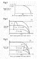
- Figs. 4 and 5 are graphs in which the horizontal axis is the throttle upstream-downstream pressure ratio Rs and the vertical axis is the engine load factor KL.
- the characteristic line L1 is a line indicating the relationship between the throttle upstream-downstream pressure ratio Rs and the engine load factor KL when the throttle opening degree TA is a first opening degree TA1
- the characteristic line L2 is a line indicating the relationship between the throttle upstream-downstream pressure ratio Rs and the engine load factor KL when the throttle opening degree TA is a second opening degree TA2.
- Fig. 4 shows an example in which the throttle opening degree TA is changed from the first opening degree TA1 to the second opening degree TA2 in a situation in which the throttle upstream-downstream pressure ratio Rs is less than the specified pressure ratio RsTh.
- the second opening degree TA2 is larger than the first opening degree TA1 (TA1 ⁇ TA2).
- the throttle upstream-downstream pressure ratio Rs used in the calculation of the second correction coefficient Kb is a value correlated with the nonlinear characteristics of the change amount of the intake air amount GA with respect to the change amount of the throttle opening degree TA in which the change characteristics of the intake air amount when the throttle opening degree TA is changed is reflected. Therefore, when the throttle upstream-downstream pressure ratio Rs is small, it can be estimated that the throttle opening degree TA is relatively small and the flow velocity of the intake air in the intake passage 17 is relatively high. When the throttle opening degree TA is increased in the case as above, the increase amount of the intake air amount GA tends to be large.
- the second correction coefficient Kb is calculated with use of the above-mentioned relational expression (Expression 2). That is, when the throttle opening degree TA is relatively small and the flow velocity of the intake air in the intake passage 17 relatively high, the second correction coefficient Kb is calculated with use of the above-mentioned relational expression (Expression 2). Therefore, the correction amount of the throttle opening degree target value TATr tends to be large due to the correction of the throttle opening degree target value TATr by the target value correction process 55.
- the throttle opening degree target value TATr is corrected so as to significantly increase by the target value correction process 55.
- the throttle opening degree target value TATr after correction that is calculated when the throttle opening degree target value TATr is changed is indicated by the bold dashed-dotted line EX0.
- the operation of the throttle valve 22 is controlled by the operation instruction value IVs calculated by the feedback control using the throttle opening degree target value TATr corrected as above. Therefore, the throttle opening degree TA changes as indicated by the solid line EX1 in Fig. 4 . That is, the throttle opening degree TA starts from the first opening degree TA1, significantly overshoots the second opening degree TA2 that is the target value of the final throttle opening degree, and then converges to the second opening degree TA2.
- the throttle valve 22 By operating the throttle valve 22 as above, the intake air amount GA can be speedily increased. That is, the delay in the change of the intake air amount GA with respect to the change of the throttle opening degree target value TATr can be suppressed.
- a case where the throttle opening degree target value TATr is corrected without using the throttle upstream-downstream pressure ratio Rs, that is, without considering the change characteristics of the intake air amount when the throttle opening degree TA is changed is indicated by the broken line CF1.
- the throttle opening degree target value TATr is corrected with use of the second correction coefficient Kb that is always equal to ⁇ (Rs) expressed by the above-mentioned relational expression (Expression 2) regardless of the size of the throttle upstream-downstream pressure ratio Rs.
- the throttle opening degree target value TATr after correction calculated when the throttle opening degree target value TATr is changed in the comparative example is indicated by the bold broken line CF0.
- the operation of the throttle valve 22 is controlled in accordance with the operation instruction value IVs calculated by the feedback control using the throttle opening degree target value corrected based on the above-mentioned pressure difference ⁇ Pm. Therefore, as indicated by the broken line CF1 in Fig. 4 , the throttle opening degree TA starts from the first opening degree TA1, significantly overshoots the second opening degree TA2, and then converges to the second opening degree TA2.
- Fig. 5 an example in which the throttle opening degree TA is increased from the first opening degree TA1 to the second opening degree TA2 in a situation in which the throttle upstream-downstream pressure ratio Rs is equal to or more than the specified pressure ratio RsTh is shown.
- the throttle upstream-downstream pressure ratio Rs is close to 1 as above, the throttle opening degree TA is relatively large and the flow velocity of the intake air in the intake passage 17 relatively low. In the case as above, it is less likely for the increase amount of the intake air amount GA to become large even when the throttle opening degree TA is increased.
- the second correction coefficient Kb is calculated with use of the above-mentioned relational expression (Expression 3). That is, when the throttle opening degree TA is relatively small or when the flow velocity of the intake air in the intake passage 17 is relatively low, the second correction coefficient Kb is calculated with use of the above-mentioned relational expression (Expression 3). Therefore, in this embodiment, in a situation as above, the second correction coefficient Kb decreases as the throttle upstream-downstream pressure ratio Rs approaches 1. Therefore, even when the target value correction process 55 corrects the throttle opening degree target value TATr, it is less likely for the correction amount of the throttle opening degree target value TATr to become large.
- the operation of the throttle valve 22 is controlled by the operation instruction value IVs calculated by the feedback control using the throttle opening degree target value TATr corrected as above. Therefore, the throttle opening degree TA changes as indicated by the solid line EX2 in Fig. 5 . That is, the throttle opening degree TA starts from the first opening degree TA1 and converges to the second opening degree TA2 after exceeding the second opening degree TA2, but the overshoot amount with respect to the second opening degree TA2 does not increase significantly.
- Fig. 5 changes in the throttle opening degree TA in the above-mentioned comparative example are shown by the broken line CF2.
- the throttle opening degree target value TATr is corrected without considering the change characteristics of the intake air amount when the throttle opening degree TA is changed. Therefore, although the intake air amount GA does not change significantly even when the throttle opening degree TA is increased, the throttle opening degree TA starts from the first opening degree TA1, significantly exceeds the second opening degree TA2, and then converges to the second opening degree TA2. That is, in the comparative example, it can be said that the throttle valve 22 is excessively operated although the response speed of the intake air amount GA hardly changes even when the operation amount of the throttle valve 22 is increased.
- the throttle opening degree target value TATr is corrected in consideration of the change characteristics of the intake air amount when the throttle opening degree TA is changed unlike the comparative example (CF2). Therefore, when the intake air amount GA does not increase significantly even when the throttle opening degree TA is increased, excessive operation of the throttle valve 22 can be suppressed.
- the throttle opening degree target value TATr is corrected in consideration of the change characteristics of the intake air amount when the throttle opening degree TA is changed.
- the delay in the change of the intake air amount GA with respect to the increase of the throttle opening degree target value TATr can be suppressed while suppressing excessive operation of the throttle valve 22.
- the second correction coefficient Kb is calculated with use of the above-mentioned relational expression (Expression 2). That is, when the throttle opening degree TA is relatively small and the flow velocity of the intake air in the intake passage 17 is relatively high, the second correction coefficient Kb is calculated with use of the above-mentioned relational expression (Expression 2). Therefore, the correction amount of the throttle opening degree target value TATr tends to be large by the correction of the throttle opening degree target value TATr by the target value correction process 55.
- the throttle opening degree target value TATr is corrected to significantly decrease by the target value correction process 55.
- the operation of the throttle valve 22 is controlled by the operation instruction value IVs calculated by the feedback control using the throttle opening degree target value TATr corrected as above. Therefore, the throttle opening degree TA starts from the second opening degree TA2, significantly undershoots the first opening degree TA1, and then converges to the first opening degree TA1.
- the intake air amount GA can be speedily reduced. That is, the delay in the change of the intake air amount GA with respect to the change of the throttle opening degree target value TATr can be suppressed.
- the second correction coefficient Kb is calculated with use of the above-mentioned relational expression (Expression 3). That is, when the throttle opening degree TA is relatively large or when the flow velocity of the intake air in the intake passage 17 is relatively low, the second correction coefficient Kb is calculated with use of the above-mentioned relational expression (Expression 3). Therefore, even when the target value correction process 55 corrects the throttle opening degree target value TATr, it is less likely for the correction amount of the throttle opening degree target value TATr to become large. As a result, even when the difference between the first opening degree TA1 and the second opening degree TA2 is large, the increase in the decrease correction amount of the throttle opening degree target value TATr by the target value correction process 55 can be suppressed.
- the operation of the throttle valve 22 is controlled based on the operation instruction value IVs calculated by the feedback control using the throttle opening degree target value TATr corrected as above. Therefore, the throttle opening degree TA starts from the second opening degree TA2, undershoots the first opening degree TA1, and then converges to the first opening degree TA1, but the undershoot amount with respect to the first opening degree TA1 does not increase significantly. As a result, when the intake air amount GA does not decrease significantly even when the throttle opening degree TA is reduced, excessive operation of the throttle valve 22 can be suppressed.
- the change amount of the above-mentioned intake air amount GA when the flow velocity of the intake air is low is less than the change amount of the above-mentioned intake air amount GA when the flow velocity of the intake air is high. Therefore, a map or a relational expression indicating the relationship between the throttle opening degree TA and the second correction coefficient Kb needs to be prepared for each flow velocity of the intake air.
- the second correction coefficient Kb is calculated with use of the throttle upstream-downstream pressure ratio Rs.
- the second correction coefficient Kb can be set to a value in accordance with the throttle opening degree TA at that time and the flow velocity of the intake air in the intake passage 17 by only preparing the above-mentioned relational expressions (Expression 2) and (Expression 3). That is, the second correction coefficient Kb can be easily calculated in this embodiment as compared to a case where the second correction coefficient Kb is calculated with use of the throttle opening degree TA and the flow velocity of the intake air in the intake passage 17 instead of the throttle upstream-downstream pressure ratio Rs, for example.
- the present embodiment may be modified as follows.
- the present embodiment and the following modifications can be combined as long as the combined modifications remain technically consistent with each other.
- the throttle opening degree target value TATr is corrected with use of the second correction coefficient Kb not only when the throttle opening degree TA is increased but also even when the throttle opening degree TA is reduced.
- the throttle opening degree target value TATr is corrected with use of the second correction coefficient Kb when the throttle opening degree TA is increased, the throttle opening degree target value TATr does not necessarily need to be corrected with use of the second correction coefficient Kb when the throttle opening degree TA is reduced.
- the throttle opening degree target value TATr is corrected with use of the second correction coefficient Kb when the throttle opening degree TA is reduced, the throttle opening degree target value TATr does not necessarily need to be corrected with use of the second correction coefficient Kb when the throttle opening degree TA is increased.
- the second correction coefficient Kb may be calculated by a different calculate method that does not use the above-mentioned relational expression (Expression 3) if the second correction coefficient Kb can be reduced as the throttle upstream-downstream pressure ratio Rs approaches 1.
- the second correction coefficient Kb may be gradually reduced as the throttle upstream-downstream pressure ratio Rs approaches 1 if the second correction coefficient Kb can be reduced as the throttle upstream-downstream pressure ratio Rs approaches 1.
- the second correction coefficient Kb does not necessarily need to be variable in accordance with the throttle upstream-downstream pressure ratio Rs if the second correction coefficient Kb can set to be less than the specified value.
- the second correction coefficient Kb may be maintained at a predetermined value that is less than the specified value.
- the second correction coefficient Kb does not necessarily need to be maintained at the specified value. That is, even when the throttle upstream-downstream pressure ratio Rs is less than the specified pressure ratio RsTh, the second correction coefficient Kb may be calculated so that the second correction coefficient Kb increases as the throttle upstream-downstream pressure ratio Rs decreases.
- the second correction process for calculating the product of the value (TATr ⁇ Gainb) calculated by the first correction process and the second correction coefficient Kb may be performed, and then process of calculating the sum of the throttle opening degree target value TATr derived by the target value derivation process 51 and the calculation result of the second correction process as the throttle opening degree target value TATr after correction may be performed.
- the throttle opening degree target value TATr can be corrected by taking the change characteristics of the intake air amount when the throttle opening degree TA is changed into account.
- the throttle opening degree TA and the flow velocity of the intake air in the intake passage 17 may be used instead of the throttle upstream-downstream pressure ratio Rs.
- the controller 50 is not limited to a device that includes an ECU or a CPU and a ROM and executes software process, but is not limited to this configuration.
- at least part of the processes executed by the software in the above-described embodiments may be executed by hardware circuits dedicated to execution of these processes (such as ASIC). That is, the controller may be modified as long as it has any one of the following configurations (a) to (c).
- a configuration including a processor that executes all of the above-described processes according to programs and a program storage device such as a ROM (including a non-transitory computer readable medium) that stores the programs.
- a plurality of software process circuits each including a processor and a program storage device and a plurality of dedicated hardware circuits may be provided. That is, the above processes may be executed in any manner as long as the processes are executed by process circuitry that includes at least one of a set of one or more software process circuits and a set of one or more dedicated hardware circuits.
Landscapes
- Engineering & Computer Science (AREA)
- Chemical & Material Sciences (AREA)
- Combustion & Propulsion (AREA)
- Mechanical Engineering (AREA)
- General Engineering & Computer Science (AREA)
- Physics & Mathematics (AREA)
- Fluid Mechanics (AREA)
- Analytical Chemistry (AREA)
- Control Of Throttle Valves Provided In The Intake System Or In The Exhaust System (AREA)
- Electrical Control Of Air Or Fuel Supplied To Internal-Combustion Engine (AREA)
- Combined Controls Of Internal Combustion Engines (AREA)
Claims (6)
- Steuergerät (50) für einen Verbrennungsmotor, wobei der Verbrennungsmotor (10) eine Drosselklappe (22) enthält, die in einem Ansaugkanal (17) vorgesehen ist, wobei das Steuergerät dazu ausgelegt ist, durchzuführen:einen Sollwertableitungsvorgang zum Ableiten eines Drosselöffnungsgradsollwerts (TATr) basierend auf einem Solldrehmoment (TrqTr) des Verbrennungsmotors (10), wobei der Drosselöffnungsgradsollwert (TATr) ein Sollwert eines Öffnungsgrades der Drosselklappe (22) ist; einen Vorgang des Berechnens einer Betätigungsgröße (IVs) der Drosselklappe (22) durch Rückkopplungssteuerung basierend auf einer Differenz (ΔTA) zwischen dem Drosselöffnungsgradsollwert (TATr) und einem Drosselöffnungsgrad (TA), der ein Öffnungsgrad der Drosselklappe (22) ist;einen Vorgang des Betätigens der Drosselklappe (22) basierend auf der Betätigungsgröße (IVs);einen Sollwertkorrekturvorgang des Korrigierens des durch den Sollwertableitungsvorgang abgeleiteten Drosselöffnungsgradsollwerts (TATr), sodass die durch die Rückkopplungssteuerung berechnete Betätigungsgröße (IVs) zunimmt; undeinen stromabwärtigen Druckerfassungsvorgang des Erfassens eines stromabwärts gelegenen Drucks (Pm), der ein Druck stromabwärts der Drosselklappe (22) im Ansaugkanal (17) ist, wobeieine Differenz zwischen dem Drosselöffnungsgradsollwert (TATr) vor der Korrektur und dem Drosselöffnungsgradsollwert nach der Korrektur als Korrekturbetrag definiert ist,eine Differenz zwischen einem erforderlichen Wert (PmR) des stromabwärts gelegenen Drucks (Pm) und dem stromabwärts gelegenen Druck (Pm) als Druckdifferenz (ΔPm) definiert ist,der Sollwertkorrekturvorgang dazu ausgelegt ist, den durch den Sollwertableitungsvorgang abgeleiteten Drosselöffnungsgradsollwert (TATr) so zu korrigieren, dassder Korrekturbetrag mit zunehmendem Absolutwert der Druckdifferenz (ΔPm) zunimmt,der Korrekturbetrag kleiner ist, wenn der Drosselöffnungsgrad (TA) groß ist, als wenn der Drosselöffnungsgrad (TA) klein ist, undder Korrekturbetrag kleiner ist, wenn eine Strömungsgeschwindigkeit der Ansaugluft im Ansaugkanal (17) niedrig ist, als wenn die Strömungsgeschwindigkeit der Ansaugluft hoch ist, wobeidas Steuergerät ferner dazu ausgelegt ist, einen stromaufwärtigen Druckerfassungsvorgang des Erfassens eines stromaufwärts gelegenen Drucks (Pa) durchzuführen, der ein Druck stromaufwärts der Drosselklappe (22) im Ansaugkanal (17) ist, undein Verhältnis des stromabwärts gelegenen Drucks (Pm) zum stromaufwärts gelegenen Druck (Pa) als Drossel-Stromaufwärts-Stromabwärts-Druckverhältnis (Rs) definiert ist,der Sollwertkorrekturvorgang dazu ausgelegt ist, durchzuführen:einen Vorgang des Berechnens eines ersten Korrekturkoeffizienten (Gainb), sodass der erste Korrekturkoeffizient (Gainb) mit zunehmender Druckdifferenz (ΔPm) zunimmt,einen Vorgang des Berechnens eines zweiten Korrekturkoeffizienten (Kb), sodass der zweite Korrekturkoeffizient (Kb) beim Annähern des Drossel-Stromaufwärts-Stromabwärts-Druckverhältnisses (Rs) an 1 abnimmt, wobei ein Überschreiten des Drosselöffnungsgrads (TA) in Bezug auf den Drosselöffnungsgradsollwert (TATr) weniger wahrscheinlich auftritt, wenn der Drosselöffnungsgrad (TA) erhöht wird, und ein Unterschreiten des Drosselöffnungsgrads (TA) in Bezug auf den Drosselöffnungsgradsollwert (TATr) weniger wahrscheinlich ist, wenn der Drosselöffnungsgrad (TA) verringert wird, undeinen Vorgang des Berechnens eines Drosselöffnungsgradsollwerts nach der Korrektur, sodass ein Absolutwert (|TATr x Gaint|) eines Produkts aus dem durch den Sollwertableitungsvorgang abgeleiteten Drosselöffnungsgradsollwert (TATr) und einem Gesamtkorrekturkoeffizienten (Gaint) gleich dem Korrekturbetrag ist, wobei der Gesamtkorrekturkoeffizient (Gaint) ein Produkt aus dem ersten Korrekturkoeffizienten (Gainb) und dem zweiten Korrekturkoeffizienten (Kb) ist.
- Steuergerät für einen Verbrennungsmotor gemäß Anspruch 1, wobei der Sollwertkorrekturvorgang dazu ausgelegt ist, den zweiten Korrekturkoeffizienten (Kb) auf einem vorgegebenen Wert (√{K/(2 (K + 1))}) zu halten, wenn das Drossel-Stromaufwärts-Stromabwärts-Druckverhältnis (Rs) kleiner als ein vorgegebenes Druckverhältnis (Rsth) ist, und
zu bewirken, dass der zweite Korrekturkoeffizient (Kb) kleiner als der vorgegebene Wert (√{K/(2 (K + 1))}) ist, wenn das Drossel-Stromaufwärts-Stromabwärts-Druckverhältnis gleich oder größer als das vorgegebene Druckverhältnis (Rsth) ist. - Steuergerät für einen Verbrennungsmotor gemäß Anspruch 2, wobei der Sollwertkorrekturvorgang dazu ausgelegt ist, den zweiten Korrekturkoeffizienten (Kb) so zu berechnen, dass der zweite Korrekturkoeffizient (Kb) mit dem Annähern des Drossel-Stromaufwärts-Stromabwärts-Druckverhältnisses (Rs) an 1 allmählich abnimmt, wenn das Drossel-Stromaufwärts-Stromabwärts-Druckverhältnis (Rs) gleich dem oder größer als das vorgegebene Druckverhältnis (Rsth) ist.
- Steuergerät für einen Verbrennungsmotor gemäß einem der Ansprüche 1 bis 3, wobei der Sollwertkorrekturvorgang dazu ausgelegt ist, den durch den Sollwertableitungsvorgang abgeleiteten Drosselöffnungsgradsollwert (TATr) zu korrigieren und zu erhöhen, wenn der Drosselöffnungsgradsollwert (TATr) zunimmt.
- Steuerungsverfahren für einen Verbrennungsmotor, wobei der Verbrennungsmotor (10) eine Drosselklappe (22) enthält, die in einem Ansaugkanal (17) vorgesehen ist, wobei das Verfahren Vorgänge umfasst, die durch ein Steuergerät ausgeführt werden, wobei die Vorgänge beinhalten:einen Sollwertableitungsvorgang zum Ableiten eines Drosselöffnungsgradsollwerts (TATr) basierend auf einem Solldrehmoment (TrqTr) des Verbrennungsmotors (10), wobei der Drosselöffnungsgradsollwert (TATr) ein Sollwert eines Öffnungsgrades der Drosselklappe (22) ist;einen Vorgang des Berechnens einer Betätigungsgröße (IVs) der Drosselklappe (22) durch Rückkopplungssteuerung basierend auf einer Differenz (ΔTA) zwischen dem Drosselöffnungsgradsollwert (TATr) und einem Drosselöffnungsgrad (TA), der ein Öffnungsgrad der Drosselklappe (22) ist;einen Vorgang des Betätigens der Drosselklappe (22) basierend auf der Betätigungsgröße (IVs);einen Sollwertkorrekturvorgang des Korrigierens des durch den Sollwertableitungsvorgang abgeleiteten Drosselöffnungsgradsollwerts (TATr), sodass die durch die Rückkopplungssteuerung berechnete Betätigungsgröße (IVs) zunimmt; undeinen stromabwärtigen Druckerfassungsvorgang des Erfassens eines stromabwärts gelegenen Drucks (Pm), der ein Druck stromabwärts der Drosselklappe (22) im Ansaugkanal (17) ist, wobei eine Differenz zwischen dem Drosselöffnungsgradsollwert (TATr) vor der Korrektur und dem Drosselöffnungsgradsollwert nach der Korrektur als Korrekturbetrag definiert ist,eine Differenz zwischen einem erforderlichen Wert (PmR) des stromabwärts gelegenen Drucks (Pm) und dem stromabwärts gelegenen Druck (Pm) als Druckdifferenz (ΔPm) definiert ist,der Sollwertkorrekturvorgang dazu ausgelegt ist, den durch den Sollwertableitungsvorgang abgeleiteten Drosselöffnungsgradssollwert (TATr) so zu korrigieren, dassder Korrekturbetrag mit zunehmendem Absolutwert der Druckdifferenz (ΔPm) zunimmt,der Korrekturbetrag kleiner ist, wenn der Drosselöffnungsgrad (TA) groß ist, als wenn der Drosselöffnungsgrad (TA) klein ist, undder Korrekturbetrag kleiner ist, wenn eine Strömungsgeschwindigkeit der Ansaugluft im Ansaugkanal (17) niedrig ist, als wenn die Strömungsgeschwindigkeit der Ansaugluft hoch ist, wobeider Vorgang ferner einen stromaufwärtigen Druckerfassungsvorgang des Erfassens eines stromaufwärtigen Drucks (Pa) beinhaltet, der ein Druck stromaufwärts der Drosselklappe (22) im Ansaugkanal (17) ist, undein Verhältnis des stromabwärts gelegenen Drucks (Pm) zum stromaufwärts gelegenen Druck (Pa) als Drossel-Stromaufwärts-Stromabwärts-Druckverhältnis (Rs) definiert ist,der Sollwertkorrekturvorgang beinhaltet:einen Vorgang des Berechnens eines ersten Korrekturkoeffizienten (Gainb), sodass der erste Korrekturkoeffizient (Gainb) mit zunehmender Druckdifferenz (ΔPm) zunimmt,einen Vorgang des Berechnens eines zweiten Korrekturkoeffizienten (Kb), sodass der zweite Korrekturkoeffizient (Kb) beim Annähern des Drossel-Stromaufwärts-Stromabwärts-Druckverhältnisses (Rs) an 1 abnimmt, wobei ein Überschreiten des Drosselöffnungsgrads (TA) in Bezug auf den Drosselöffnungsgradsollwert (TATr) weniger wahrscheinlich auftritt, wenn der Drosselöffnungsgrad (TA) erhöht wird, und ein Unterschreiten des Drosselöffnungsgrads (TA) in Bezug auf den Drosselöffnungsgradsollwert (TATr) weniger wahrscheinlich ist, wenn der Drosselöffnungsgrad (TA) verringert wird, undeinen Vorgang des Berechnens eines Drosselöffnungsgradsollwerts nach der Korrektur, sodass ein Absolutwert (|TATr x Gaint|) eines Produkts aus dem durch den Sollwertableitungsvorgang abgeleiteten Drosselöffnungsgradsollwert (TATr) und einem Gesamtkorrekturkoeffizienten (Gaint) gleich dem Korrekturbetrag ist, wobei der Gesamtkorrekturkoeffizient (Gaint) ein Produkt aus dem ersten Korrekturkoeffizienten (Gainb) und dem zweiten Korrekturkoeffizienten (Kb) ist.
- Nicht-flüchtiges computerlesbares Speichermedium, das ein Programm speichert, das einen Prozessor veranlasst, einen Steuervorgang eines Verbrennungsmotors auszuführen, wobei der Verbrennungsmotor (10) eine Drosselklappe (22) enthält, das in einem Ansaugkanal (17) vorgesehen ist, wobei der Steuervorgang beinhaltet:einen Sollwertableitungsvorgang zum Ableiten eines Drosselöffnungsgradsollwerts (TATr) basierend auf einem Solldrehmoment (TrqTr) des Verbrennungsmotors (10), wobei der Drosselöffnungsgradsollwert (TATr) ein Sollwert eines Öffnungsgrades der Drosselklappe (22) ist; einen Vorgang des Berechnens einer Betätigungsgröße (IVs) der Drosselklappe (22) durch Rückkopplungssteuerung basierend auf einer Differenz (ΔTA) zwischen dem Drosselöffnungsgradsollwert (TATr) und einem Drosselöffnungsgrad (TA), der ein Öffnungsgrad der Drosselklappe (22) ist;einen Vorgang des Betätigens der Drosselklappe (22) basierend auf der Betätigungsgröße (IVs);einen Sollwertkorrekturvorgang des Korrigierens des durch den Sollwertableitungsvorgang abgeleiteten Drosselöffnungsgradsollwerts (TATr), sodass die durch die Rückkopplungssteuerung berechnete Betätigungsgröße (IVs) zunimmt; undeinen stromabwärtigen Druckerfassungsvorgang des Erfassens eines stromabwärts gelegenen Drucks (Pm), der ein Druck stromabwärts der Drosselklappe (22) im Ansaugkanal (17) ist, wobeieine Differenz zwischen dem Drosselöffnungsgradsollwert (TATr) vor der Korrektur und dem Drosselöffnungsgradsollwert nach der Korrektur als Korrekturbetrag definiert ist,eine Differenz zwischen einem erforderlichen Wert (PmR) des stromabwärts gelegenen Drucks (Pm) und dem stromabwärts gelegenen Druck (Pm) als Druckdifferenz (ΔPm) definiert ist,der Sollwertkorrekturvorgang dazu ausgelegt ist, den durch den Sollwertableitungsvorgang abgeleiteten Drosselöffnungsgradsollwert (TATr) so zu korrigieren, dass der Korrekturbetrag mit zunehmendem Absolutwert der Druckdifferenz (ΔPm) zunimmt,der Korrekturbetrag kleiner ist, wenn der Drosselöffnungsgrad (TA) groß ist, als wenn der Drosselöffnungsgrad (TA) klein ist, undder Korrekturbetrag kleiner ist, wenn eine Strömungsgeschwindigkeit der Ansaugluft im Ansaugkanal (17) niedrig ist, als wenn die Strömungsgeschwindigkeit der Ansaugluft hoch ist, wobeider Vorgang ferner einen stromaufwärtigen Druckerfassungsvorgang des Erfassens eines stromaufwärtigen Drucks (Pa) beinhaltet, der ein Druck stromaufwärts der Drosselklappe (22) im Ansaugkanal (17) ist, undein Verhältnis des stromabwärts gelegenen Drucks (Pm) zum stromaufwärts gelegenen Druck (Pa) als Drossel-Stromaufwärts-Stromabwärts-Druckverhältnis (Rs) definiert ist,der Sollwertkorrekturvorgang beinhaltet:einen Vorgang des Berechnens eines ersten Korrekturkoeffizienten (Gainb), sodass der erste Korrekturkoeffizient (Gainb) mit zunehmender Druckdifferenz (ΔPm) zunimmt,einen Vorgang des Berechnens eines zweiten Korrekturkoeffizienten (Kb), sodass der zweite Korrekturkoeffizient (Kb) beim Annähern des Drossel-Stromaufwärts-Stromabwärts-Druckverhältnisses (Rs) an 1 abnimmt, wobei ein Überschreiten des Drosselöffnungsgrads (TA) in Bezug auf den Drosselöffnungsgradsollwert (TATr) weniger wahrscheinlich auftritt, wenn der Drosselöffnungsgrad (TA) erhöht wird, und ein Unterschreiten des Drosselöffnungsgrads (TA) in Bezug auf den Drosselöffnungsgradsollwert (TATr) weniger wahrscheinlich ist, wenn der Drosselöffnungsgrad (TA) verringert wird, undeinen Vorgang des Berechnens eines Drosselöffnungsgradsollwerts nach der Korrektur, sodass ein Absolutwert (|TATr x Gaint|) eines Produkts aus dem durch den Sollwertableitungsvorgang abgeleiteten Drosselöffnungsgradsollwert (TATr) und einem Gesamtkorrekturkoeffizienten (Gaint) gleich dem Korrekturbetrag ist, wobei der Gesamtkorrekturkoeffizient (Gaint) ein Produkt aus dem ersten Korrekturkoeffizienten (Gainb) und dem zweiten Korrekturkoeffizienten (Kb) ist.
Applications Claiming Priority (1)
| Application Number | Priority Date | Filing Date | Title |
|---|---|---|---|
| JP2018049319A JP7004161B2 (ja) | 2018-03-16 | 2018-03-16 | 内燃機関の制御装置 |
Publications (2)
| Publication Number | Publication Date |
|---|---|
| EP3540199A1 EP3540199A1 (de) | 2019-09-18 |
| EP3540199B1 true EP3540199B1 (de) | 2021-04-21 |
Family
ID=65812069
Family Applications (1)
| Application Number | Title | Priority Date | Filing Date |
|---|---|---|---|
| EP19162596.1A Active EP3540199B1 (de) | 2018-03-16 | 2019-03-13 | Steuergerät und steuerungsverfahren für verbrennungsmotor |
Country Status (4)
| Country | Link |
|---|---|
| US (1) | US10738719B2 (de) |
| EP (1) | EP3540199B1 (de) |
| JP (1) | JP7004161B2 (de) |
| CN (1) | CN110273763B (de) |
Families Citing this family (3)
| Publication number | Priority date | Publication date | Assignee | Title |
|---|---|---|---|---|
| IT201800009528A1 (it) * | 2018-10-17 | 2020-04-17 | Fpt Ind Spa | Dispositivo di controllo di una valvola a farfalla di un motore a combustione interna e motore a combustione interna comprendente detto dispositivo |
| JP7135719B2 (ja) * | 2018-10-24 | 2022-09-13 | トヨタ自動車株式会社 | スロットル制御装置 |
| CN114151209B (zh) * | 2021-11-17 | 2023-07-18 | 潍柴动力股份有限公司 | 发动机节气门开度控制方法、装置、电子设备及存储介质 |
Family Cites Families (21)
| Publication number | Priority date | Publication date | Assignee | Title |
|---|---|---|---|---|
| JPH03189354A (ja) | 1989-12-18 | 1991-08-19 | Mazda Motor Corp | 過給機付エンジンの制御装置 |
| JPH08144820A (ja) | 1994-11-22 | 1996-06-04 | Honda Motor Co Ltd | 内燃エンジンのスロットル弁制御装置 |
| JP3593896B2 (ja) | 1998-09-17 | 2004-11-24 | 日産自動車株式会社 | エンジンの制御装置 |
| JP2004100642A (ja) * | 2002-09-12 | 2004-04-02 | Toyota Motor Corp | 内燃機関の制御装置および制御方法 |
| JP4114574B2 (ja) * | 2003-08-26 | 2008-07-09 | トヨタ自動車株式会社 | 内燃機関の吸気量制御装置及び吸気量制御方法 |
| JP4207718B2 (ja) * | 2003-08-26 | 2009-01-14 | トヨタ自動車株式会社 | 内燃機関の制御装置 |
| JP4254761B2 (ja) * | 2005-08-22 | 2009-04-15 | トヨタ自動車株式会社 | 過給器付き内燃機関の制御装置 |
| JP4465665B2 (ja) * | 2005-11-29 | 2010-05-19 | トヨタ自動車株式会社 | 内燃機関の制御装置および制御方法 |
| JP4614104B2 (ja) * | 2006-10-16 | 2011-01-19 | 株式会社デンソー | 内燃機関の吸入空気量検出装置 |
| JP4488318B2 (ja) * | 2008-05-20 | 2010-06-23 | 三菱電機株式会社 | 内燃機関制御装置 |
| JP5197548B2 (ja) * | 2009-11-05 | 2013-05-15 | 本田技研工業株式会社 | 内燃機関の燃料噴射制御装置 |
| JP5530790B2 (ja) * | 2010-04-15 | 2014-06-25 | 本田技研工業株式会社 | 内燃機関の吸入空気量制御装置 |
| JP5625533B2 (ja) | 2010-06-22 | 2014-11-19 | トヨタ自動車株式会社 | 内燃機関の制御装置 |
| JP5598366B2 (ja) * | 2011-02-16 | 2014-10-01 | 三菱自動車工業株式会社 | エンジンの制御装置 |
| CN103827474B (zh) * | 2011-11-10 | 2016-03-09 | 本田技研工业株式会社 | 内燃机的进气控制装置 |
| JP5328967B1 (ja) * | 2012-10-25 | 2013-10-30 | 三菱電機株式会社 | 内燃機関のシリンダ吸入空気量推定装置 |
| JP6051793B2 (ja) | 2012-11-07 | 2016-12-27 | 日産自動車株式会社 | 内燃機関の制御装置 |
| JP5716771B2 (ja) * | 2013-02-25 | 2015-05-13 | トヨタ自動車株式会社 | 内燃機関の制御装置 |
| JP2015021434A (ja) * | 2013-07-19 | 2015-02-02 | トヨタ自動車株式会社 | 内燃機関のスロットル制御装置 |
| JP2016196833A (ja) * | 2015-04-02 | 2016-11-24 | トヨタ自動車株式会社 | スロットル通過空気流量推定装置 |
| JP6395167B1 (ja) * | 2017-07-19 | 2018-09-26 | 三菱電機株式会社 | 内燃機関の制御装置 |
-
2018
- 2018-03-16 JP JP2018049319A patent/JP7004161B2/ja not_active Expired - Fee Related
-
2019
- 2019-01-29 US US16/260,107 patent/US10738719B2/en not_active Expired - Fee Related
- 2019-03-06 CN CN201910168029.3A patent/CN110273763B/zh not_active Expired - Fee Related
- 2019-03-13 EP EP19162596.1A patent/EP3540199B1/de active Active
Non-Patent Citations (1)
| Title |
|---|
| None * |
Also Published As
| Publication number | Publication date |
|---|---|
| CN110273763B (zh) | 2022-02-18 |
| JP7004161B2 (ja) | 2022-01-21 |
| CN110273763A (zh) | 2019-09-24 |
| JP2019157821A (ja) | 2019-09-19 |
| US10738719B2 (en) | 2020-08-11 |
| US20190285009A1 (en) | 2019-09-19 |
| EP3540199A1 (de) | 2019-09-18 |
Similar Documents
| Publication | Publication Date | Title |
|---|---|---|
| EP2930339B1 (de) | Vorrichtung zur motordrehzahlsteuerung | |
| EP3540199B1 (de) | Steuergerät und steuerungsverfahren für verbrennungsmotor | |
| JP2009002251A (ja) | 内燃機関の空燃比制御装置 | |
| CA2716569C (en) | Engine | |
| JP2621084B2 (ja) | アイドル回転数制御装置 | |
| EP2436914B1 (de) | Motorsteuerungsvorrichtung | |
| US10871115B2 (en) | Method for controlling internal combustion engine and device for controlling same | |
| EP2930338B1 (de) | Vorrichtung zur motordrehzahlsteuerung | |
| JP2000234543A (ja) | 高圧燃料噴射系の燃料圧制御装置 | |
| JP5751344B2 (ja) | 内燃機関の制御装置 | |
| JP7030888B2 (ja) | 内燃機関制御装置 | |
| JP7256477B2 (ja) | 内燃機関の制御装置 | |
| EP2942513A2 (de) | Motordrehzahlsteuerungsvorrichtung | |
| JP2017110549A (ja) | 内燃機関の制御装置 | |
| JP4710716B2 (ja) | 内燃機関の空燃比制御装置 | |
| JP6603150B2 (ja) | 内燃機関の燃料噴射制御装置 | |
| JP7181943B2 (ja) | エンジン制御装置及びエンジン制御方法 | |
| US10294879B2 (en) | Control apparatus for internal combustion engine with supercharger and method for controlling internal combustion engine with supercharger | |
| JP4548373B2 (ja) | 内燃機関の空燃比制御装置 | |
| JP4737052B2 (ja) | 内燃機関の停止位置制御装置 | |
| JP2008070232A (ja) | 内燃機関の制御装置 | |
| JP4510704B2 (ja) | 内燃機関の燃料噴射制御装置 | |
| EP1908945A1 (de) | Vorrichtung und Verfahren zur Steuerung eines Verbrennungsmotors | |
| JP4770589B2 (ja) | 内燃機関の空燃比制御装置 | |
| JP4844522B2 (ja) | 内燃機関の制御装置 |
Legal Events
| Date | Code | Title | Description |
|---|---|---|---|
| PUAI | Public reference made under article 153(3) epc to a published international application that has entered the european phase |
Free format text: ORIGINAL CODE: 0009012 |
|
| STAA | Information on the status of an ep patent application or granted ep patent |
Free format text: STATUS: REQUEST FOR EXAMINATION WAS MADE |
|
| 17P | Request for examination filed |
Effective date: 20190411 |
|
| AK | Designated contracting states |
Kind code of ref document: A1 Designated state(s): AL AT BE BG CH CY CZ DE DK EE ES FI FR GB GR HR HU IE IS IT LI LT LU LV MC MK MT NL NO PL PT RO RS SE SI SK SM TR |
|
| AX | Request for extension of the european patent |
Extension state: BA ME |
|
| GRAP | Despatch of communication of intention to grant a patent |
Free format text: ORIGINAL CODE: EPIDOSNIGR1 |
|
| STAA | Information on the status of an ep patent application or granted ep patent |
Free format text: STATUS: GRANT OF PATENT IS INTENDED |
|
| RIC1 | Information provided on ipc code assigned before grant |
Ipc: F02D 41/00 20060101ALI20200930BHEP Ipc: F02D 11/10 20060101AFI20200930BHEP Ipc: F02D 41/14 20060101ALI20200930BHEP |
|
| INTG | Intention to grant announced |
Effective date: 20201028 |
|
| GRAS | Grant fee paid |
Free format text: ORIGINAL CODE: EPIDOSNIGR3 |
|
| GRAA | (expected) grant |
Free format text: ORIGINAL CODE: 0009210 |
|
| STAA | Information on the status of an ep patent application or granted ep patent |
Free format text: STATUS: THE PATENT HAS BEEN GRANTED |
|
| RIN1 | Information on inventor provided before grant (corrected) |
Inventor name: OTANI, TOSHIAKI Inventor name: WANIBE, MASAHIRO |
|
| AK | Designated contracting states |
Kind code of ref document: B1 Designated state(s): AL AT BE BG CH CY CZ DE DK EE ES FI FR GB GR HR HU IE IS IT LI LT LU LV MC MK MT NL NO PL PT RO RS SE SI SK SM TR |
|
| REG | Reference to a national code |
Ref country code: GB Ref legal event code: FG4D |
|
| REG | Reference to a national code |
Ref country code: CH Ref legal event code: EP |
|
| REG | Reference to a national code |
Ref country code: DE Ref legal event code: R096 Ref document number: 602019003972 Country of ref document: DE |
|
| REG | Reference to a national code |
Ref country code: IE Ref legal event code: FG4D |
|
| REG | Reference to a national code |
Ref country code: AT Ref legal event code: REF Ref document number: 1384865 Country of ref document: AT Kind code of ref document: T Effective date: 20210515 |
|
| REG | Reference to a national code |
Ref country code: LT Ref legal event code: MG9D |
|
| REG | Reference to a national code |
Ref country code: AT Ref legal event code: MK05 Ref document number: 1384865 Country of ref document: AT Kind code of ref document: T Effective date: 20210421 |
|
| REG | Reference to a national code |
Ref country code: NL Ref legal event code: MP Effective date: 20210421 |
|
| PG25 | Lapsed in a contracting state [announced via postgrant information from national office to epo] |
Ref country code: FI Free format text: LAPSE BECAUSE OF FAILURE TO SUBMIT A TRANSLATION OF THE DESCRIPTION OR TO PAY THE FEE WITHIN THE PRESCRIBED TIME-LIMIT Effective date: 20210421 Ref country code: HR Free format text: LAPSE BECAUSE OF FAILURE TO SUBMIT A TRANSLATION OF THE DESCRIPTION OR TO PAY THE FEE WITHIN THE PRESCRIBED TIME-LIMIT Effective date: 20210421 Ref country code: LT Free format text: LAPSE BECAUSE OF FAILURE TO SUBMIT A TRANSLATION OF THE DESCRIPTION OR TO PAY THE FEE WITHIN THE PRESCRIBED TIME-LIMIT Effective date: 20210421 Ref country code: NL Free format text: LAPSE BECAUSE OF FAILURE TO SUBMIT A TRANSLATION OF THE DESCRIPTION OR TO PAY THE FEE WITHIN THE PRESCRIBED TIME-LIMIT Effective date: 20210421 Ref country code: AT Free format text: LAPSE BECAUSE OF FAILURE TO SUBMIT A TRANSLATION OF THE DESCRIPTION OR TO PAY THE FEE WITHIN THE PRESCRIBED TIME-LIMIT Effective date: 20210421 Ref country code: BG Free format text: LAPSE BECAUSE OF FAILURE TO SUBMIT A TRANSLATION OF THE DESCRIPTION OR TO PAY THE FEE WITHIN THE PRESCRIBED TIME-LIMIT Effective date: 20210721 |
|
| PG25 | Lapsed in a contracting state [announced via postgrant information from national office to epo] |
Ref country code: SE Free format text: LAPSE BECAUSE OF FAILURE TO SUBMIT A TRANSLATION OF THE DESCRIPTION OR TO PAY THE FEE WITHIN THE PRESCRIBED TIME-LIMIT Effective date: 20210421 Ref country code: RS Free format text: LAPSE BECAUSE OF FAILURE TO SUBMIT A TRANSLATION OF THE DESCRIPTION OR TO PAY THE FEE WITHIN THE PRESCRIBED TIME-LIMIT Effective date: 20210421 Ref country code: PT Free format text: LAPSE BECAUSE OF FAILURE TO SUBMIT A TRANSLATION OF THE DESCRIPTION OR TO PAY THE FEE WITHIN THE PRESCRIBED TIME-LIMIT Effective date: 20210823 Ref country code: PL Free format text: LAPSE BECAUSE OF FAILURE TO SUBMIT A TRANSLATION OF THE DESCRIPTION OR TO PAY THE FEE WITHIN THE PRESCRIBED TIME-LIMIT Effective date: 20210421 Ref country code: NO Free format text: LAPSE BECAUSE OF FAILURE TO SUBMIT A TRANSLATION OF THE DESCRIPTION OR TO PAY THE FEE WITHIN THE PRESCRIBED TIME-LIMIT Effective date: 20210721 Ref country code: LV Free format text: LAPSE BECAUSE OF FAILURE TO SUBMIT A TRANSLATION OF THE DESCRIPTION OR TO PAY THE FEE WITHIN THE PRESCRIBED TIME-LIMIT Effective date: 20210421 Ref country code: GR Free format text: LAPSE BECAUSE OF FAILURE TO SUBMIT A TRANSLATION OF THE DESCRIPTION OR TO PAY THE FEE WITHIN THE PRESCRIBED TIME-LIMIT Effective date: 20210722 Ref country code: IS Free format text: LAPSE BECAUSE OF FAILURE TO SUBMIT A TRANSLATION OF THE DESCRIPTION OR TO PAY THE FEE WITHIN THE PRESCRIBED TIME-LIMIT Effective date: 20210821 |
|
| REG | Reference to a national code |
Ref country code: DE Ref legal event code: R097 Ref document number: 602019003972 Country of ref document: DE |
|
| PG25 | Lapsed in a contracting state [announced via postgrant information from national office to epo] |
Ref country code: DK Free format text: LAPSE BECAUSE OF FAILURE TO SUBMIT A TRANSLATION OF THE DESCRIPTION OR TO PAY THE FEE WITHIN THE PRESCRIBED TIME-LIMIT Effective date: 20210421 Ref country code: CZ Free format text: LAPSE BECAUSE OF FAILURE TO SUBMIT A TRANSLATION OF THE DESCRIPTION OR TO PAY THE FEE WITHIN THE PRESCRIBED TIME-LIMIT Effective date: 20210421 Ref country code: RO Free format text: LAPSE BECAUSE OF FAILURE TO SUBMIT A TRANSLATION OF THE DESCRIPTION OR TO PAY THE FEE WITHIN THE PRESCRIBED TIME-LIMIT Effective date: 20210421 Ref country code: SM Free format text: LAPSE BECAUSE OF FAILURE TO SUBMIT A TRANSLATION OF THE DESCRIPTION OR TO PAY THE FEE WITHIN THE PRESCRIBED TIME-LIMIT Effective date: 20210421 Ref country code: SK Free format text: LAPSE BECAUSE OF FAILURE TO SUBMIT A TRANSLATION OF THE DESCRIPTION OR TO PAY THE FEE WITHIN THE PRESCRIBED TIME-LIMIT Effective date: 20210421 Ref country code: EE Free format text: LAPSE BECAUSE OF FAILURE TO SUBMIT A TRANSLATION OF THE DESCRIPTION OR TO PAY THE FEE WITHIN THE PRESCRIBED TIME-LIMIT Effective date: 20210421 Ref country code: ES Free format text: LAPSE BECAUSE OF FAILURE TO SUBMIT A TRANSLATION OF THE DESCRIPTION OR TO PAY THE FEE WITHIN THE PRESCRIBED TIME-LIMIT Effective date: 20210421 |
|
| PLBE | No opposition filed within time limit |
Free format text: ORIGINAL CODE: 0009261 |
|
| STAA | Information on the status of an ep patent application or granted ep patent |
Free format text: STATUS: NO OPPOSITION FILED WITHIN TIME LIMIT |
|
| 26N | No opposition filed |
Effective date: 20220124 |
|
| PGFP | Annual fee paid to national office [announced via postgrant information from national office to epo] |
Ref country code: DE Payment date: 20220203 Year of fee payment: 4 |
|
| PG25 | Lapsed in a contracting state [announced via postgrant information from national office to epo] |
Ref country code: IS Free format text: LAPSE BECAUSE OF FAILURE TO SUBMIT A TRANSLATION OF THE DESCRIPTION OR TO PAY THE FEE WITHIN THE PRESCRIBED TIME-LIMIT Effective date: 20210821 Ref country code: AL Free format text: LAPSE BECAUSE OF FAILURE TO SUBMIT A TRANSLATION OF THE DESCRIPTION OR TO PAY THE FEE WITHIN THE PRESCRIBED TIME-LIMIT Effective date: 20210421 |
|
| PGFP | Annual fee paid to national office [announced via postgrant information from national office to epo] |
Ref country code: FR Payment date: 20220209 Year of fee payment: 4 |
|
| PG25 | Lapsed in a contracting state [announced via postgrant information from national office to epo] |
Ref country code: IT Free format text: LAPSE BECAUSE OF FAILURE TO SUBMIT A TRANSLATION OF THE DESCRIPTION OR TO PAY THE FEE WITHIN THE PRESCRIBED TIME-LIMIT Effective date: 20210421 |
|
| PG25 | Lapsed in a contracting state [announced via postgrant information from national office to epo] |
Ref country code: MC Free format text: LAPSE BECAUSE OF FAILURE TO SUBMIT A TRANSLATION OF THE DESCRIPTION OR TO PAY THE FEE WITHIN THE PRESCRIBED TIME-LIMIT Effective date: 20210421 |
|
| REG | Reference to a national code |
Ref country code: CH Ref legal event code: PL |
|
| REG | Reference to a national code |
Ref country code: BE Ref legal event code: MM Effective date: 20220331 |
|
| PG25 | Lapsed in a contracting state [announced via postgrant information from national office to epo] |
Ref country code: LU Free format text: LAPSE BECAUSE OF NON-PAYMENT OF DUE FEES Effective date: 20220313 Ref country code: LI Free format text: LAPSE BECAUSE OF NON-PAYMENT OF DUE FEES Effective date: 20220331 Ref country code: IE Free format text: LAPSE BECAUSE OF NON-PAYMENT OF DUE FEES Effective date: 20220313 Ref country code: CH Free format text: LAPSE BECAUSE OF NON-PAYMENT OF DUE FEES Effective date: 20220331 |
|
| PG25 | Lapsed in a contracting state [announced via postgrant information from national office to epo] |
Ref country code: BE Free format text: LAPSE BECAUSE OF NON-PAYMENT OF DUE FEES Effective date: 20220331 |
|
| P01 | Opt-out of the competence of the unified patent court (upc) registered |
Effective date: 20230427 |
|
| REG | Reference to a national code |
Ref country code: DE Ref legal event code: R119 Ref document number: 602019003972 Country of ref document: DE |
|
| GBPC | Gb: european patent ceased through non-payment of renewal fee |
Effective date: 20230313 |
|
| PG25 | Lapsed in a contracting state [announced via postgrant information from national office to epo] |
Ref country code: GB Free format text: LAPSE BECAUSE OF NON-PAYMENT OF DUE FEES Effective date: 20230313 |
|
| PG25 | Lapsed in a contracting state [announced via postgrant information from national office to epo] |
Ref country code: GB Free format text: LAPSE BECAUSE OF NON-PAYMENT OF DUE FEES Effective date: 20230313 Ref country code: FR Free format text: LAPSE BECAUSE OF NON-PAYMENT OF DUE FEES Effective date: 20230331 Ref country code: DE Free format text: LAPSE BECAUSE OF NON-PAYMENT OF DUE FEES Effective date: 20231003 |
|
| PG25 | Lapsed in a contracting state [announced via postgrant information from national office to epo] |
Ref country code: MK Free format text: LAPSE BECAUSE OF FAILURE TO SUBMIT A TRANSLATION OF THE DESCRIPTION OR TO PAY THE FEE WITHIN THE PRESCRIBED TIME-LIMIT Effective date: 20210421 Ref country code: CY Free format text: LAPSE BECAUSE OF FAILURE TO SUBMIT A TRANSLATION OF THE DESCRIPTION OR TO PAY THE FEE WITHIN THE PRESCRIBED TIME-LIMIT Effective date: 20210421 |
|
| PG25 | Lapsed in a contracting state [announced via postgrant information from national office to epo] |
Ref country code: HU Free format text: LAPSE BECAUSE OF FAILURE TO SUBMIT A TRANSLATION OF THE DESCRIPTION OR TO PAY THE FEE WITHIN THE PRESCRIBED TIME-LIMIT; INVALID AB INITIO Effective date: 20190313 |
|
| PG25 | Lapsed in a contracting state [announced via postgrant information from national office to epo] |
Ref country code: MT Free format text: LAPSE BECAUSE OF FAILURE TO SUBMIT A TRANSLATION OF THE DESCRIPTION OR TO PAY THE FEE WITHIN THE PRESCRIBED TIME-LIMIT Effective date: 20210421 |
|
| PG25 | Lapsed in a contracting state [announced via postgrant information from national office to epo] |
Ref country code: TR Free format text: LAPSE BECAUSE OF FAILURE TO SUBMIT A TRANSLATION OF THE DESCRIPTION OR TO PAY THE FEE WITHIN THE PRESCRIBED TIME-LIMIT Effective date: 20210421 |