EP3540169B1 - Abstandhaltermontagevorrichtung zur herstellung von isolierglasscheiben und verfahren zur herstellung von isolierglasscheiben - Google Patents
Abstandhaltermontagevorrichtung zur herstellung von isolierglasscheiben und verfahren zur herstellung von isolierglasscheiben Download PDFInfo
- Publication number
- EP3540169B1 EP3540169B1 EP17868690.3A EP17868690A EP3540169B1 EP 3540169 B1 EP3540169 B1 EP 3540169B1 EP 17868690 A EP17868690 A EP 17868690A EP 3540169 B1 EP3540169 B1 EP 3540169B1
- Authority
- EP
- European Patent Office
- Prior art keywords
- pillar
- substrate
- glass panel
- panel unit
- base material
- Prior art date
- Legal status (The legal status is an assumption and is not a legal conclusion. Google has not performed a legal analysis and makes no representation as to the accuracy of the status listed.)
- Active
Links
Images







Classifications
-
- B—PERFORMING OPERATIONS; TRANSPORTING
- B26—HAND CUTTING TOOLS; CUTTING; SEVERING
- B26F—PERFORATING; PUNCHING; CUTTING-OUT; STAMPING-OUT; SEVERING BY MEANS OTHER THAN CUTTING
- B26F1/00—Perforating; Punching; Cutting-out; Stamping-out; Apparatus therefor
- B26F1/02—Perforating by punching, e.g. with relatively-reciprocating punch and bed
- B26F1/14—Punching tools; Punching dies
-
- B—PERFORMING OPERATIONS; TRANSPORTING
- B26—HAND CUTTING TOOLS; CUTTING; SEVERING
- B26F—PERFORATING; PUNCHING; CUTTING-OUT; STAMPING-OUT; SEVERING BY MEANS OTHER THAN CUTTING
- B26F1/00—Perforating; Punching; Cutting-out; Stamping-out; Apparatus therefor
- B26F1/38—Cutting-out; Stamping-out
- B26F1/44—Cutters therefor; Dies therefor
-
- C—CHEMISTRY; METALLURGY
- C03—GLASS; MINERAL OR SLAG WOOL
- C03C—CHEMICAL COMPOSITION OF GLASSES, GLAZES OR VITREOUS ENAMELS; SURFACE TREATMENT OF GLASS; SURFACE TREATMENT OF FIBRES OR FILAMENTS MADE FROM GLASS, MINERALS OR SLAGS; JOINING GLASS TO GLASS OR OTHER MATERIALS
- C03C27/00—Joining pieces of glass to pieces of other inorganic material; Joining glass to glass other than by fusing
- C03C27/06—Joining glass to glass by processes other than fusing
-
- E—FIXED CONSTRUCTIONS
- E06—DOORS, WINDOWS, SHUTTERS, OR ROLLER BLINDS IN GENERAL; LADDERS
- E06B—FIXED OR MOVABLE CLOSURES FOR OPENINGS IN BUILDINGS, VEHICLES, FENCES OR LIKE ENCLOSURES IN GENERAL, e.g. DOORS, WINDOWS, BLINDS, GATES
- E06B3/00—Window sashes, door leaves, or like elements for closing wall or like openings; Layout of fixed or moving closures, e.g. windows in wall or like openings; Features of rigidly-mounted outer frames relating to the mounting of wing frames
- E06B3/66—Units comprising two or more parallel glass or like panes permanently secured together
- E06B3/663—Elements for spacing panes
- E06B3/66304—Discrete spacing elements, e.g. for evacuated glazing units
-
- E—FIXED CONSTRUCTIONS
- E06—DOORS, WINDOWS, SHUTTERS, OR ROLLER BLINDS IN GENERAL; LADDERS
- E06B—FIXED OR MOVABLE CLOSURES FOR OPENINGS IN BUILDINGS, VEHICLES, FENCES OR LIKE ENCLOSURES IN GENERAL, e.g. DOORS, WINDOWS, BLINDS, GATES
- E06B3/00—Window sashes, door leaves, or like elements for closing wall or like openings; Layout of fixed or moving closures, e.g. windows in wall or like openings; Features of rigidly-mounted outer frames relating to the mounting of wing frames
- E06B3/66—Units comprising two or more parallel glass or like panes permanently secured together
- E06B3/663—Elements for spacing panes
- E06B3/66309—Section members positioned at the edges of the glazing unit
- E06B3/66314—Section members positioned at the edges of the glazing unit of tubular shape
- E06B3/66319—Section members positioned at the edges of the glazing unit of tubular shape of rubber, plastics or similar materials
-
- E—FIXED CONSTRUCTIONS
- E06—DOORS, WINDOWS, SHUTTERS, OR ROLLER BLINDS IN GENERAL; LADDERS
- E06B—FIXED OR MOVABLE CLOSURES FOR OPENINGS IN BUILDINGS, VEHICLES, FENCES OR LIKE ENCLOSURES IN GENERAL, e.g. DOORS, WINDOWS, BLINDS, GATES
- E06B3/00—Window sashes, door leaves, or like elements for closing wall or like openings; Layout of fixed or moving closures, e.g. windows in wall or like openings; Features of rigidly-mounted outer frames relating to the mounting of wing frames
- E06B3/66—Units comprising two or more parallel glass or like panes permanently secured together
- E06B3/663—Elements for spacing panes
- E06B3/66309—Section members positioned at the edges of the glazing unit
- E06B3/66342—Section members positioned at the edges of the glazing unit characterised by their sealed connection to the panes
-
- E—FIXED CONSTRUCTIONS
- E06—DOORS, WINDOWS, SHUTTERS, OR ROLLER BLINDS IN GENERAL; LADDERS
- E06B—FIXED OR MOVABLE CLOSURES FOR OPENINGS IN BUILDINGS, VEHICLES, FENCES OR LIKE ENCLOSURES IN GENERAL, e.g. DOORS, WINDOWS, BLINDS, GATES
- E06B3/00—Window sashes, door leaves, or like elements for closing wall or like openings; Layout of fixed or moving closures, e.g. windows in wall or like openings; Features of rigidly-mounted outer frames relating to the mounting of wing frames
- E06B3/66—Units comprising two or more parallel glass or like panes permanently secured together
- E06B3/673—Assembling the units
- E06B3/67304—Preparing rigid spacer members before assembly
-
- E—FIXED CONSTRUCTIONS
- E06—DOORS, WINDOWS, SHUTTERS, OR ROLLER BLINDS IN GENERAL; LADDERS
- E06B—FIXED OR MOVABLE CLOSURES FOR OPENINGS IN BUILDINGS, VEHICLES, FENCES OR LIKE ENCLOSURES IN GENERAL, e.g. DOORS, WINDOWS, BLINDS, GATES
- E06B3/00—Window sashes, door leaves, or like elements for closing wall or like openings; Layout of fixed or moving closures, e.g. windows in wall or like openings; Features of rigidly-mounted outer frames relating to the mounting of wing frames
- E06B3/66—Units comprising two or more parallel glass or like panes permanently secured together
- E06B3/673—Assembling the units
- E06B3/67326—Assembling spacer elements with the panes
-
- E—FIXED CONSTRUCTIONS
- E06—DOORS, WINDOWS, SHUTTERS, OR ROLLER BLINDS IN GENERAL; LADDERS
- E06B—FIXED OR MOVABLE CLOSURES FOR OPENINGS IN BUILDINGS, VEHICLES, FENCES OR LIKE ENCLOSURES IN GENERAL, e.g. DOORS, WINDOWS, BLINDS, GATES
- E06B3/00—Window sashes, door leaves, or like elements for closing wall or like openings; Layout of fixed or moving closures, e.g. windows in wall or like openings; Features of rigidly-mounted outer frames relating to the mounting of wing frames
- E06B3/66—Units comprising two or more parallel glass or like panes permanently secured together
- E06B3/677—Evacuating or filling the gap between the panes ; Equilibration of inside and outside pressure; Preventing condensation in the gap between the panes; Cleaning the gap between the panes
-
- B—PERFORMING OPERATIONS; TRANSPORTING
- B26—HAND CUTTING TOOLS; CUTTING; SEVERING
- B26F—PERFORATING; PUNCHING; CUTTING-OUT; STAMPING-OUT; SEVERING BY MEANS OTHER THAN CUTTING
- B26F2210/00—Perforating, punching, cutting-out, stamping-out, severing by means other than cutting of specific products
- B26F2210/02—Perforating, punching, cutting-out, stamping-out, severing by means other than cutting of specific products of stacked sheets
-
- E—FIXED CONSTRUCTIONS
- E06—DOORS, WINDOWS, SHUTTERS, OR ROLLER BLINDS IN GENERAL; LADDERS
- E06B—FIXED OR MOVABLE CLOSURES FOR OPENINGS IN BUILDINGS, VEHICLES, FENCES OR LIKE ENCLOSURES IN GENERAL, e.g. DOORS, WINDOWS, BLINDS, GATES
- E06B3/00—Window sashes, door leaves, or like elements for closing wall or like openings; Layout of fixed or moving closures, e.g. windows in wall or like openings; Features of rigidly-mounted outer frames relating to the mounting of wing frames
- E06B3/66—Units comprising two or more parallel glass or like panes permanently secured together
- E06B3/677—Evacuating or filling the gap between the panes ; Equilibration of inside and outside pressure; Preventing condensation in the gap between the panes; Cleaning the gap between the panes
- E06B3/6775—Evacuating or filling the gap during assembly
Definitions
- the present invention relates to a pillar mounting device for manufacturing a glass panel unit and a glass panel unit manufacturing method.
- Patent Literature 1 describes a glass panel unit including pillars sandwiched between a pair of substrates.
- Patent Literature 1 describes a manufacturing method including a step of manufacturing pillars, a step of once storing the pillars thus manufactured, and a step of mounting the pillars stored on one of the pair of substrates. Therefore, this manufacturing method includes a large number of steps and is thus inefficient.
- WO 2013/019838 describes a pillar mounting device for manufacturing a glass panel unit according to the preamble of claim 1 and a glass panel unit manufacturing method according to the preamble of claim 7.
- Patent Literature 1 JP H11-79799 A
- a sheet of the pillar mounting device and used in the manufacturing method is a sheet for forming pillars for a glass panel unit and includes a base material having a sheet-like shape.
- the base material has a plurality of loop-shaped grooves.
- the base material has a plurality of portions serving as the pillars. Each of the plurality of portions is surrounded by a corresponding one of the plurality of loop-shaped grooves.
- Each of the plurality of loop-shaped grooves is a groove having a continuous or discontinuous loop shape.
- a pillar mounting device according to the invention is defined in appended claim 1.
- a manufacturing method of another aspect of the present invention is a manufacturing method for a glass panel unit and includes a punching step, a pillar mounting step, and a bonding step as defined in appended claim 7.
- FIGS. 1 , 3, and 4 each schematically illustrate a pillar mounting device of a first example.
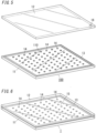
- the pillar mounting device is a device configured to mount pillars 14 on one surface 110 of a substrate 11 to manufacture a pillar mounting substrate 100 (see FIG. 5 ).
- the pillar mounting substrate 100 forms a part of a glass panel unit 1 and has a structure including a plurality of pillars 14 mounted on the surface 110 of the substrate 11.
- Another substrate 12 is placed on the pillar mounting substrate 100 to face the surface 110 of the substrate 11, and peripheral edges of the substrates 11 and 12 facing each other are bonded with a sealing member 13 having a frame shape, thereby obtaining the glass panel unit 1 (see FIG. 6 ) having an inside space 15.
- the substrates 11 and 12 are both glass panes which are transparent but which may be semi-transparent or non-transparent. Moreover, the substrates 11 and 12 each include at least a glass pane and preferably include a coating such as a thermal ray reflecting film in addition to the glass pane.
- the substrate 11 and the substrate 12 are respectively referred to as a "first substrate 11" and a “second substrate 12" to be distinguished from each other.
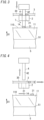
- the pillar mounting device includes a substrate supporting part 5, a support table 2 installed above the substrate supporting part 5, a sheet 3 supported in a horizontal position by the support table 2, and a punch 4 installed above the sheet 3.
- an arrow D1 indicates the up direction, and a direction opposite to the direction indicated by the arrow D1 is the down direction.
- the substrate supporting part 5 has a support surface 51 which supports the first substrate 11.
- the substrate supporting part 5 supports the first substrate 11 in a position in which the surface 110 faces upward.
- the substrate supporting part 5 may have any appropriate structure.
- the support table 2 is provided to be located above the surface 110 of the first substrate 11 supported by the substrate supporting part 5.
- the support table 2 has a through hole 21 penetrating therethrough in the up-down direction.
- the support table 2 has an upper surface on which the sheet 3 is put to cover the through hole 21.
- the sheet 3 includes a base material 30 in sheet form (film form).
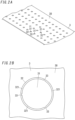
- the base material 30 has a plurality of (a large number of) loop-shaped grooves 32.
- the plurality of loop-shaped grooves 32 are disposed with a distance to one another in a matrix form (see FIG. 2A ).
- the base material 30 is preferably made of a resin, but other materials such as metal, glass, ceramic, or wood may be adopted as long as they are materials that can be punched with the punch 4.
- a base material including a plurality of stacked resin layers may be adopted.
- the base material 30 is made of a resin, it is possible to form pillars 14 each having a low thermal conductivity. Moreover, when the resin of which the base material 30 is made is polyimide, excellent heat resistance is provided.
- each of the loop-shaped grooves 32 includes so-called perforations discontinuously formed by laser processing with, for example, a laser machine. That is, each of the loop-shaped grooves 32 includes a plurality of (three) grooves 321 each having an arc shape. Each of the loop-shaped grooves 32 is located to surround a corresponding one of the portions 31. Each of the portions 31 has a round shape in plan view. These grooves 321 each having an arc shape penetrate through the base material 30 in a thickness direction (the up-down direction) thereof. Between adjacent two of the grooves 321 each having an arc shape, a connection portion 33 is formed.
- a means for forming each groove 321 is not limited to the laser processing. It is also possible to form each groove 321 by another means such as etching process.
- connection portions 33 in the sheet 3 of the present embodiment are formed at a plurality of locations (three locations) at equal intervals in the circumferential direction along the outer shape of each portion 31.
- the connection portions 33 are portions connecting the portion 31 of the base material 30 surrounded by the loop-shaped groove 32 to the remaining portion of the base material 30.
- the punch 4 includes a pin 42 protruding downward.
- the pin 42 has a columnar (cylindrical) shape.
- the pin 42 is configured such that a tip surface (lower surface) of the pin 42 downward punches the portion 31 from the base material 30 of the sheet 3.
- the portion 31 is surrounded by the loop-shaped groove 32.
- the sheet 3 is supported by the support table 2.
- the through hole 21 in the support table 2 is located below the tip surface of the pin 42 with the sheet 3 placed between the tip surface and the support table 2.
- the pin 42 has such a dimensional shape that allows the pin to penetrate through the through hole 21.
- the manufacturing method according to the present embodiment includes a disposition step S1, a punching step S2, a pillar mounting step S3, a displacement step S4, a bonding step S5, and a process step S6.
- the punching step S2 and the pillar mounting step S3 following the punching step S2 are repeated a plurality of times with the displacement step S4 performed between sets each including the punching step S2 and the pillar mounting step S3 which are repeated. Then, the bonding step S5 and the process step S6 are performed.
- the substrate supporting part 5, the support table 2, the sheet 3, and the punch 4 are disposed (see FIG. 1 ) such that the substrate supporting part 5 supports the first substrate 11, the support table 2 is located above the first substrate 11, the support table 2 supports the sheet 3, and the punch 4 is located above the sheet 3.
- the sheet 3 is disposed to cover the upper surface of the support table 2.
- the pin 42 included in the punch 4 is located directly above the through hole 21 in the support table 2 with the sheet 3 placed between the pin 42 and the support table 2.
- the punch 4 including the pin 42 is driven downward.
- the punch 4 is driven downward, and thereby, the pin 42 having a columnar shape downward punches the portion 31 surrounded by the loop-shaped groove 32 from the base material 30 of the sheet 3 through the through hole 21 in the support table 2 (see the void arrow in FIG. 3 ).
- connection portion 33 (see FIG. 2B ) of the sheet 3 are broken by external force exerted by the pin 42.
- the portion 31 surrounded by the loop-shaped groove 32 is punched to have a columnar shape with reduced formation of burrs.
- the base material 30 of the sheet 3 is made of a resin
- burrs are likely to be formed due to punching, but the pillar mounting device of the present embodiment effectively reduces the burrs.
- the base material 30 includes a plurality of resin layers
- burrs are likely to be formed due to punching, but the pillar mounting device of the present embodiment effectively reduces the formation of burrs.
- the portion 31 which has been punched out downward by the pin 42 and which has a columnar shape is placed on the surface 110 of the first substrate 11 with the portion 31 being pressed onto the tip surface of the pin 42.
- the portion 31 having a columnar shape and being placed on the surface 110 forms the pillar 14.
- Liquid such as water is preferably applied to a location on the surface 110 of the first substrate 11 where the pillar 14 is to be placed. The presence of the liquid reduces dislocation of the pillar 14 on the surface 110.
- the pin 42 is displaced upward as indicated by the void arrow in FIG. 4 , and then, the first substrate 11 and the sheet 3 are displaced in the horizontal direction relative to the support table 2 and the punch 4 respectively.
- the travel direction of the first substrate 11 may be the same as or different from the travel direction of the sheet 3.
- FIG. 4 shows a case where the first substrate 11 and the sheet 3 are displaced, but the pillar mounting device may be configured such that the punch 4 and the support table 2 are displaced, or the pillar mounting device may be configured such that the first substrate 11 and the sheet 3 are displaced and the punch 4 and the support table 2 are displaced. Alternatively, the pillar mounting device may be configured such that the support table 2, the sheet 3, and the punch 4 are displaced relative to the first substrate 11 and the sheet 3 is displaced relative to the support table 2 and the punch 4.
- next punching step S2 of a large number of portions 31 included in the sheet 3, a portion 31 which has not been punched and remains is punched with the pin 42.
- the portion 31 thus punched forms another pillar 14.
- the pillar 14 is mounted on the surface 110 of the first substrate 11 by the pin 42.
- the punching step S2 and the pillar mounting step S3 following the punching step S2 are repeated a plurality of times with the displacement step S4 performed between sets each including the punching step S2 and the pillar mounting step S3 which are repeated.
- the punching step S2 and the pillar mounting step S3 are performed a plurality of times, and thereby, the plurality of pillars 14 are mounted with a distance to each other on the surface 110 of the first substrate 11.
- the pillar mounting substrate 100 (see FIG. 5 ) including a plurality of pillars 14 is efficiently manufactured.
- the pillars When a large number of pillars are manufactured in advance and are stored as described in the prior art technique, the pillars may be adsorbed on each other due to static electricity or the like. In contrast, according to the manufacturing method of the present example, it is possible to reduce pillars 14 adsorbed on each other.
- a material for the pillars 14 that is, as a material for the sheet 3
- the manufacturing method of the present example reduces formation of burrs formed at the portion 31 punched from the base material 30. This increases the strength (compressive strength) of the pillar 14 formed of the portion 31.
- the sealing member 13 having a frame shape is disposed on a peripheral portion of the surface 110 of the first substrate 11.
- the sealing member 13 is located on the surface 110 of the first substrate 11 to surround the plurality of pillars 14.
- the second substrate 12 is placed to sandwich the plurality of pillars 14 and the sealing member 13 between the second substrate 12 and the first substrate 11, and the first substrate 11 and the second substrate 12 are bonded together with the sealing member 13.
- the inside space 15 is formed between the first substrate 11 the second substrate 12 thus bonded (see FIG. 6 ).
- the plurality of pillars 14 are located. Each pillar 14 is in contact with the first substrate 11 and the second substrate 12 and maintains the distance between the first substrate 11 and the second substrate 12.
- a pressure in the inside space 15 is reduced to a prescribed degree of vacuum (e.g., degree of vacuum lower than or equal to 0.1 Pa), or gas (dry air, argon, or the like) having thermal insulation properties is supplied to the inside space 15, and then, the ventilation hole 16 is sealed.
- a prescribed degree of vacuum e.g., degree of vacuum lower than or equal to 0.1 Pa
- gas dry air, argon, or the like
- the process step S6 forms the glass panel unit 1 as illustrated in FIG. 6 .
- a sealing site of the ventilation hole 16 is omitted.
- the glass panel unit 1 has the inside space 15 between the first substrate 11 and the second substrate 12.
- the inside space 15 is hermetically sealed with a reduced pressure therein or with gas supplied therein.
- the glass panel unit 1 has the inside space 15 and thus has a high thermal insulation property.
- a glass panel unit 1 may be formed by a manufacturing method without the process step S6.
- the glass panel unit 1 formed by this manufacturing method of the case also has thermal insulation properties to some extent.
- a large number of pillars 14 are disposed with the substantially same distance to one another in a matrix form between the first substrate 11 and the second substrate 12.
- the number and locations of the pillars 14 are not particularly limited.
- One pillar 14 may be disposed on the surface 110 of the first substrate 11.
- the loop-shaped groove 32 includes a plurality of grooves 321 penetrating the base material 30 of the sheet 3 in the thickness direction of the base material 30.
- the loop-shaped groove 32 may include a non-through groove 322.
- the non-through groove 322 is formed by laser processing on one surface of, for example, the sheet 3 to have a continuous loop shape.
- a means for forming the loop-shaped groove 32 having such a continuous shape is not limited to the laser processing, but another means such as an etching process enables the loop-shaped groove 32 to be formed.
- loop-shaped grooves 32 may have a discontinuous loop shape and may be formed not to penetrate through the base material 30.
- the loop-shaped groove 32 has an annular shape, but the shape of the loop-shaped groove 32 is not limited to this embodiment.
- the shape of the loop-shaped groove 32 may be, for example, a polygonal shape (quadrangular shape, hexagonal shape, or the like), or other shapes (ellipse shape, Reuleaux triangle-shape, star shape, or the like).
- the portion 31 surrounded by the loop-shaped groove 32 is punched from the base material 30, thereby forming the pillar 14 having a shape corresponding to the shape of the loop-shaped groove 32.
- the plurality of loop-shaped grooves 32 are disposed with a distance to each other in the base material 30 of the sheet 3.
- no distance may be formed between adjacent loop-shaped grooves 32.
- adjacent loop-shaped grooves 32 may share a part thereof (part on one side of the quadrangular shape).
- a plurality of (a large number of) portions 31 each having a quadrangular shape are arranged in rows and columns, that is, in a matrix form.
- the plurality of (a large number of) loop-shaped grooves 32 each having a quadrangular shape and surrounding the portions 31 are combined altogether to form a grid groove structure including a plurality of longitudinal grooves and a plurality of lateral grooves transverse to one another.
- the portions 31 surrounded by the respective loop-shaped grooves 32 are punched from the base material 30, thereby forming quadrangular prism pillars 14.
- the pillar mounting device of this example it is possible to manufacture a variation of the glass panel unit 1 as illustrated in FIGS. 9 and 10 and it is possible to manufacture a glass window 6 as illustrated in FIG. 12 .
- the variation of the glass panel unit 1 illustrated in FIGS. 9 and 10 includes a third substrate 17 and a frame member 181 in addition to the components of the glass panel unit 1 shown in FIG. 6 .
- the third substrate 17 is located to face the second substrate 12.
- the frame member 181 hermetically bonds entire peripheral portions of the second substrate 12 and the third substrate 17 together.
- the third substrate 17 includes at least a glass pane similarly to the first substrate 11 and the second substrate 12 and may adopt an appropriate panel.
- the third substrate 17 is transparent generally but may be semi-transparent or non-transparent.
- a space 185 which is sealed is formed between counter surfaces 120 and 170 respectively of the second substrate 12 and the third substrate 17.
- the third substrate 17 is located to face one of the first substrate 11 and the second substrate 12. Although not shown in the figure, when the third substrate 17 is disposed to face the first substrate 11, the frame member 181 is bonded to peripheral portions of the first substrate 11 and the third substrate 17, and the space 185 is formed between the first substrate 11 and the third substrate 17.
- a spacer 182 is further disposed on an inner side of the frame member 181.
- the spacer 182 has a frame shape having a hollow.
- the hollow of the spacer 182 is filled with desiccant 184.
- the spacer 182 is made of metal such as aluminum and has a through hole 183 on an inner circumferential side thereof.
- the hollow of the spacer 182 is in communication with the space 185 via the through hole 183.
- the desiccant 184 may be a silica gel, for example.
- the frame member 181 is preferably made of, for example, a highly airtight resin such as a silicon resin and butyl rubber.
- the space 185 is a space hermetically sealed with the second substrate 12 (or the first substrate 11), the third substrate 17, and the frame member 181.
- the space 185 is filled with a dry gas.
- the dry gas is, for example, a dry rare gas such as argon gas or dry air.
- the dry air includes air dried after sealed in the space 185 due to the effect of the desiccant 184.
- the inside space 15 and the space 185 are provided between the third substrate 17 and the first substrate 11 (or the second substrate 12), thereby providing a high thermal insulation property.
- the third substrate 17 is located on one end in a thickness direction of the glass panel unit 1, and the first substrate 11 (or the second substrate 12) is located on the other end in the thickness direction.
- the inside space 15 has a pressure reduced to a prescribed degree of vacuum or is supplied with gas.
- the space 185 is filled with a drying gas.
- the manufacturing method of the variation of the glass panel unit 1 includes a second bonding step S7 performed after the process step S6 in addition to the steps shown in FIG. 7 .
- the second bonding step S7 is a step of bonding the third substrate 17 to one of the first substrate 11 and the second substrate 12 with a frame member 181 disposed between the third substrate 17 and the one of the first substrate 11 and the second substrate 12.
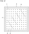
- a glass window 6 shown in FIG. 12 has a structure in which a window frame 19 is fitted to the glass panel unit 1 shown in FIG. 6 , and the glass window 6 has a high thermal insulation property.
- the sealing member 13 of the glass panel unit 1 is preferably hidden by the window frame 19 when viewed from the front side.
- a manufacturing method of the glass window 6 includes a fitting step S8 of fitting the window frame 19 to the glass panel unit 1 in addition to the steps shown in FIG. 7 .
- a target to which the window frame 19 is fitted is not limited to the glass panel unit 1 as shown in FIG. 6 .
- the window frame 19 may be fitted to a glass panel unit 1 as illustrated in, for example, FIGS. 9 and 10 . In each case, a glass window 6 having a high thermal insulation property is obtained.
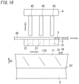
- a pillar mounting device of a second example will be described with reference to FIGS. 14 to 16 .
- components of the pillar mounting device of the present example components similar to those of the first example are denoted by the same reference signs, and the detailed description thereof will be omitted.
- the components of the pillar mounting device components different from those of the first example will be mainly described.
- a support table 2 included in the pillar mounting device of the present example has a plurality of through holes 21 (see FIG. 15 ).
- the plurality of through holes 21 have the same dimensional shape and are located with a distance to one another.
- the plurality of through holes 21 are located in a matrix form in plan view.
- a punch 4 included in the pillar mounting device includes a plurality of pins 42.
- the plurality of pins 42 have the same dimensional shape and are located with a distance to one another.
- the plurality of pins 42 are located in a matrix form in plan view.
- the arrangement pattern of the plurality of pins 42 corresponds to the arrangement pattern of the plurality of through holes 21 in plan view.
- the plurality of pins 42 may be driven into the plurality of through holes 21 located below on a one-to-one basis.
- the pillar mounting device is configured to drive the plurality of pins 42 altogether but may be configured to drive the plurality of pins 42 individually.
- the manufacturing method of the present example includes a disposition step S1, a punching step S2, a pillar mounting step S3, a displacement step S4, a bonding step S5, and a process step S6.
- a disposition step S1 a punching step S2, a pillar mounting step S3, a displacement step S4, a bonding step S5, and a process step S6.
- a substrate supporting part 5, a first substrate 11, a support table 2, a sheet 3, and a punch 4 are disposed in this order (see FIG. 14 ).
- the sheet 3 has a base material 30 in which a plurality of (a large number of) loop-shaped grooves 32 are formed in advance in a matrix form.
- the plurality of pins 42 are disposed to correspond to the plurality of loop-shaped grooves 32 on a one-to-one basis.
- the plurality of pins 42 included in the punch 4 are driven into the sheet 3 (see the void arrow in FIG. 15 ).
- portions 31 surrounded by the plurality of loop-shaped grooves 32 are punched downward from the base material 30. That is, the plurality of portions 31 are punched from the base material 30 by one time of punching.
- the plurality of portions 31 punched from the base material 30 with the plurality of pins 42 are, immediately after being punched, mounted as is on a surface 110 of the first substrate 11 by the plurality of pins 42.
- the plurality of portions 31 mounted on the surface 110 form respective pillars 14.
- the plurality of pins 42 for forming the plurality of pillars 14 in the punching step S2 functions as a movement mechanism 7 (see FIG. 15 ) configured to move the plurality of pillars 14 immediately after being formed to the surface 110 of the first substrate 11.
- liquid such as water is preferably applied to locations on the surface 110 of the first substrate 11 where the plurality of pillars 14 are to be mounted.
- the presence of the liquid reduces dislocation of each pillar 14 on the surface 110.
- the plurality of pins 42 are displaced upward, and then, the first substrate 11 and the sheet 3 are displaced in the horizontal direction relative to the support table 2 and the punch 4 respectively (see the void arrow in FIG. 16 ).
- the punching step S2 and the pillar mounting step S3 following the punching step S2 are repeated a plurality of times with the displacement step S4 performed between sets each including the punching step S2 and the pillar mounting step S3 which are repeated.
- a pillar mounting substrate 100 including a plurality of (a large number of) pillars 14 is manufactured.
- the pillar mounting substrate 100 may be manufactured. In this case, the displacement step S4 is not required.
- the bonding step S5 and the process step S6 are similar to those in the first example. Further performing both the steps S5 and S6 provides a glass panel unit 1 including the pillar mounting substrate 100 and having a high thermal insulation property.
- further performing a second bonding step S7 enables a glass panel unit 1 including three layers to be manufactured.
- further performing a fitting step S8 enables a glass window 6 having a high thermal insulation property to be manufactured.
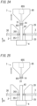
- a pillar mounting device of a first embodiment will be described with reference to FIGS. 17 to 19 .
- components similar to those of the first example are denoted by the same reference signs, and the detailed description thereof will be omitted.
- the components of the pillar mounting device of the present embodiment components different from those of the first example will be mainly described.
- the pillar mounting device of the present embodiment includes a support table 2, a sheet 3 held in a horizontal position by the support table 2, and a punch 4 installed above the sheet 3.
- the support table 2 includes a lower member 23 and an upper member 24.
- the lower member 23 has a groove 231 that is recessed downward.
- the upper member 24 has a through hole 241 penetrating therethrough in the up-down direction.
- An upper end of the groove 231 has an opening, and a lower end of the groove 231 has a bottom surface 233.
- a small gap is provided, and the sheet 3 is disposed in the gap.
- the sheet 3 has a base material 30 in which a plurality of (a large number of) loop-shaped grooves 32 are formed in a matrix form (see FIG. 2A ).
- the punch 4 has a suction pin 43 which has a hollow and which protrudes downward.
- the suction pin 43 is configured such that a tip surface (lower surface) of the suction pin 43 downward punches a portion 31 from the base material 30 of the sheet 3.
- the portion 31 is surrounded by the loop-shaped groove 32.
- the sheet 3 is supported by the support table 2.
- the groove 231 in the lower member 23 is located below the tip surface of the suction pin 43 with the sheet 3 placed between the tip surface and the lower member 23.
- the tip surface of the suction pin 43 has an inlet 431 formed therein.
- the inlet 431 is in communication with a space 45 formed in the punch 4 through a hollow section 432 of the suction pin 43. Reducing a pressure in the space 45 with, for example, a vacuum pump enables the tip surface of the suction pin 43 to be in vacuum contact with the pillar 14.
- a disposition step S1 the support table 2, the sheet 3, and the punch 4 are disposed (see FIG. 17 ) such that the support table 2 supports the sheet 3 and the suction pin 43 is located above the sheet 3.
- the suction pin 43 is located directly above the groove 231 in the lower member 23 of the support table 2 with the sheet 3 placed between the suction pin 43 and the lower member 23.
- the suction pin 43 included in the punch 4 is driven downward through the through hole 241 in the upper member 24.
- the suction pin 43 downward punches the portion 31 surrounded by a loop-shaped groove 32 from the base material 30 of the sheet 3 through the groove 231 of the lower member 23 downward (see the void arrow in FIG. 18 ).
- connection portions 33 (see FIG. 2B ) of the sheet 3 are broken by external force exerted by the suction pin 43.
- the portion 31 surrounded by the loop-shaped groove 32 is punched to have a columnar shape with reduced formation of burrs.
- the portion 31 which is punched out with the suction pin 43 and which has a columnar shape is pressed against the bottom surface 233 of the groove 231 with the portion 31 being pressed against the tip surface of the suction pin 43.
- the portion 31 having a columnar shape and being pressed against the bottom surface 233 forms the pillar 14.
- the suction pin 43 is in vacuum contact with the pillar 14 pressed against the tip surface.
- the punch 4 is driven upward (see the void arrow in FIG. 19 ) with the vacuum contact of the suction pin 43 with the pillar 14 being maintained to move the pillar 14 to a prescribed location on a surface 110 of a first substrate 11 (see, for example, FIG. 5 ).
- the suction pin 43 functions as a movement mechanism 7.
- the suction pin 43 is configured to punch part of the base material 30 to form the pillar 14 in the punching step S2.
- the movement mechanism 7 is configured to move the pillar 14 to the surface 110 of the first substrate 11.
- the sheet 3 is displaced in the horizontal direction relative to the support table 2.
- a next punching step S2 and a next pillar mounting step S3 are performed.
- next punching step S2 of a large number of portions 31 included in the sheet 3, a portion 31 which is not punched and remains is punched with the suction pin 43.
- the portion 31 thus punched forms another pillar 14.
- the pillar 14 is mounted on the surface 110 of the first substrate 11 by the suction pin 43.
- the punching step S2 and the pillar mounting step S3 following the punching step S2 are repeated a plurality of times with the displacement step S4 performed between sets each including the punching step S2 and the pillar mounting step S3 which are repeated.
- the pillar mounting substrate 100 see FIG. 5 ) including the plurality of pillars 14 is efficiently manufactured.
- Steps of manufacturing a glass panel unit 1 and a glass window 6 each including the pillar mounting substrate 100 thus manufactured are similar to the steps described in the first example.
- a bonding step S5 and a process step S6 similar to those of the first example are further performed to manufacture a glass panel unit 1 as illustrated in FIG. 6 .
- the bonding step S5, the process step S6, and a second bonding step S7 similar to those of the first example are further performed to manufacture a glass panel unit 1 having a three-layer structure as illustrated in FIGS. 9 and 10 .
- the bonding step S5, the process step S6, and a fitting step S8 similar to those of the first example are further performed to manufacture a glass window 6 as illustrated in FIG. 12 .
- the punch 4 includes one suction pin 43, but the punch 4 may include a plurality of suction pins 43.
- the plurality of suction pins 43 included in the punch 4 punch a plurality of portions 31 from the base material 30 of the sheet 3, thereby forming a plurality of pillars 14.
- the plurality of suction pins 43 may be driven altogether or individually.
- the plurality of pillars 14 thus formed are mounted on the surface 110 of the first substrate 11 with the plurality of pillars 14 being in vacuum contact with the plurality of suction pins 43.
- the plurality of suction pins 43 function as movement mechanisms 7 configured to move the plurality of pillars 14 thus formed to the surface 110 of the first substrate 11.
- a timing at which the suction pin 43 starts sucking air through the inlet 431 may be a timing at which the suction pin 43 punches a portion 31 from the base material 30, or before or after this timing.
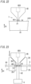
- a pillar mounting device of a second embodiment will be descried based on FIGS. 20 to 22 .
- components similar to those of the first example are denoted by the same reference signs, and the detailed description thereof will be omitted.
- the components of the pillar mounting device of the present embodiment components different from those of the first example will be mainly described.
- the pillar mounting device of the present embodiment includes a table 81 having a surface 810 which is flat and which faces upward, a support table 2 installed above the table 81, a sheet 3 supported in a horizontal position by the support table 2, and a punch 4 installed above the sheet 3.
- the configurations of the support table 2, the sheet 3, and the punch 4 are similar to those in the first example. .
- the table 81, the support table 2, the sheet 3, and the punch 4 are disposed (see FIG. 20 ) such that the support table 2 is located above the table 81, the support table 2 supports the sheet 3, and the punch 4 is located above the sheet 3.
- a pin 42 included in the punch 4 is driven downward through a through hole 21 in the support table 2.
- the pin 42 downward punches a portion 31 surrounded by a loop-shaped groove 32 from a base material 30 of the sheet 3 through the through hole 21 (see the void arrow in FIG. 21 ).
- the portion 31 punched by the pin 42 forms a pillar 14.
- the pillar 14 is placed on the surface 810 of the table 81 with the pillar 14 being pressed against a tip surface of the pin 42.
- a suction tool 83 (see FIG. 22 ) different from the punch 4 comes into vacuum contact with the pillar 14 placed on the table 81.
- the suction tool 83 has an end surface in which an inlet 831 is formed.
- the inlet 831 is in communication with a space 835 formed in the suction tool 83. Reducing a pressure in the space 835 with, for example, a vacuum pump enables the inlet 831 of the suction tool 83 to be in vacuum contact with the pillar 14.
- the suction tool 83 moves the pillar 14 to a prescribed location on a surface 110 of a first substrate 11 (see, for example, FIG. 5 ) with the vacuum contact of the inlet 831 with the pillar 14 being maintained. That is, in the manufacturing method of the present embodiment, the suction tool 83 functions as a movement mechanism 7 configured to move the pillar 14 to the surface 110 of the first substrate 11.
- the sheet 3 and the table 81 are displaced in the horizontal direction relative to the support table 2.
- a next punching step S2 and a next pillar mounting step S3 are performed.
- next punching step S2 of a large number of portions 31 included in the sheet 3, a portion 31 which has not been punched and remains is punched with the pin 42.
- the portion 31 thus punched forms another pillar 14.
- the pillar 14 is mounted on the surface 110 of the first substrate 11 by the suction tool 83.
- the punching step S2 and the pillar mounting step S3 following the punching step S2 are repeated a plurality of times with the displacement step S4 performed between sets each including the punching step S2 and the pillar mounting step S3 which are repeated.
- the pillar mounting substrate 100 see FIG. 5 ) including a plurality of pillars 14 is efficiently manufactured.
- Steps of manufacturing a glass panel unit 1 and a glass window 6 each including the pillar mounting substrate 100 thus manufactured are similar to the steps described in the first example.
- a bonding step S5 and a process step S6 similar to those of the first example are further performed to manufacture a glass panel unit 1 as illustrated in FIG. 6 .
- the bonding step S5, the process step S6, and a second bonding step S7 similar to those of the first example are further performed to manufacture a glass panel unit 1 having a three-layer structure as illustrated in FIGS. 9 and 10 .
- the bonding step S5, the process step S6, and a fitting step S8 similar to those of the first embodiment are further performed to manufacture a glass window 6 as illustrated in FIG. 12 .
- the punch 4 includes one pin 42, but the punch 4 may include a plurality of pins 42.
- the plurality of pins 42 included in the punch 4 punch a plurality of portions 31 from the base material 30 of the sheet 3, thereby forming a plurality of pillars 14.
- the plurality of pins 42 may be driven altogether or individually.
- the plurality of pillars 14 thus formed are mounted on the surface 110 of the first substrate 11 with the pillars 14 being in vacuum contact with the plurality of suction tools 83. That is, the plurality of suction tools 83 function as movement mechanisms 7 configured to move the plurality of pillars 14 thus formed to the surface 110 of the first substrate 11.
- a pillar mounting device of a third embodiment will be descried based on FIGS. 23 to 25 .
- components similar to those of the first example are denoted by the same reference signs, and the detailed description thereof will be omitted.
- the components of the pillar mounting device of the present embodiment components different from those of the first example will be mainly described.
- the pillar mounting device of the present embodiment includes a support table 2, a sheet 3 held in a horizontal position by the support table 2, a punch 4 installed below the sheet 3, and a suction tool 85 installed above the sheet 3.
- the support table 2 includes a lower member 25 and an upper member 26.
- the lower member 25 has a through hole 251 vertically penetrating therethrough.
- the upper member 26 has a through hole 261 vertically penetrating therethrough. Between the lower member 25 and the upper member 26, a small gap is provided, and the sheet 3 is disposed in the gap.
- the sheet 3 has a base material 30 in which a plurality of (a large number of) loop-shaped grooves 32 are formed in a matrix form (see FIG. 2A ).
- the punch 4 has a pin 42 protruding upward.
- the pin 42 is configured such that a tip surface (upper surface) of the pin 42 punches a portion 31 upward from the base material 30 of the sheet 3.
- the portion 31 is surrounded by the loop-shaped groove 32.
- the sheet 3 is supported by the support table 2.
- the suction tool 85 is located above the tip surface of the pin 42 with the sheet 3 placed between the tip surface and the suction tool 85.
- the suction tool 85 has an end surface (lower surface) in which an inlet 851 is formed.
- the inlet 851 is in communication with a space 855 formed in the suction tool 85. Reducing a pressure in the space 855 with, for example, a vacuum pump enables the inlet 851 of the suction tool 85 to be in vacuum contact with the pillar 14.
- the support table 2, the sheet 3, the punch 4, and the suction tool 85 are disposed such that the support table 2 supports the sheet 3, the punch 4 is located below the sheet 3, and the suction tool 85 is located above the sheet 3 (see FIG. 23 ).
- the pin 42 of the punch 4 and the inlet 851 of the suction tool 85 are located on respective sides of the sheet 3 (portion 31).
- the pin 42 included in the punch 4 is driven upward through the through hole 251 in the lower member 25.
- the pin 42 upward punches a portion 31 surrounded by the loop-shaped groove 32 from the base material 30 of the sheet 3 through hole 261 of the upper member 26 (see the void arrow in FIG. 24 ).
- the portion 31 upward punched by the pin 42 and having a columnar shape forms the pillar 14.
- the pillar 14 is pressed against the inlet 851 of the suction tool 85 with the pillar 14 being pressed against the tip surface of the pin 42.
- the inlet 851 of the suction tool 85 abuts on the portion 31 of the sheet 3 before the pin 42 is driven upward.
- the pillar mounting device of the present embodiment is configured to pushes up both the portion 31 (pillar 14) and the suction tool 85 when the pin 42 punches the portion 31 from the base material 30.
- the suction tool 85 may be out of contact with the sheet 3. In this case, after the pin 42 punches the portion 31 from the base material 30, the suction tool 85 abuts on and sucks up the portion 31 (pillar 14).
- the suction tool 85 moves the pillar 14 to a prescribed location on a surface 110 of a first substrate 11 (see, for example, FIG. 5 ). That is, in the manufacturing method of the present embodiment, the suction tool 85 function as a movement mechanism 7 configured to move the pillar 14 thus formed to the surface 110 of the first substrate 11.
- a timing at which the suction tool 85 starts sucking air through the inlet 851 may be a timing at which the pin 42 punches the portion 31 from the base material 30, or before or after this timing.
- the sheet 3 is displaced in the horizontal direction relative to the support table 2, the punch 4, and the suction tool 85.
- a next punching step S2 and a next pillar mounting step S3 are performed.
- next punching step S2 of a large number of portions 31 included in the sheet 3, a portion 31 which has not been punched and remains is punched with the pin 42.
- the portion 31 thus punched forms another pillar 14.
- the pillar 14 is mounted on the surface 110 of the first substrate 11 by the suction tool 85.
- the punching step S2 and the pillar mounting step S3 following the punching step S2 are repeated a plurality of times with the displacement step S4 performed between sets each of which including the punching step S2 and the pillar mounting step S3 which are repeated.
- the pillar mounting substrate 100 see FIG. 5 ) including a plurality of pillars 14 is efficiently manufactured.
- Steps of manufacturing a glass panel unit 1 and a glass window 6 each including the pillar mounting substrate 100 thus manufactured are similar to the steps described in the first example.
- a bonding step S5 and a process step S6 similar to those of the first example are further performed to manufacture a glass panel unit 1 as illustrated in FIG. 6 .
- the bonding step S5, the process step S6, and a second bonding step S7 similar to those of the first example are further performed to manufacture a glass panel unit 1 having a three-layer structure as illustrated in FIGS. 9 and 10 .
- the bonding step S5, the process step S6, and a fitting step S8 similar to those of the first embodiment are further performed to manufacture a glass window 6 as illustrated in FIG. 12 .
- the punch 4 includes one pin 42 and one suction tool 85 is provided, but the punch 4 may include a plurality of pins 42, and a plurality of suction tools 85 may be provided.
- the plurality of pins 42 included in the punch 4 punch a plurality of portions 31 from the base material 30 of the sheet 3, thereby forming a plurality of pillars 14.
- the plurality of pins 42 may be driven altogether or individually.
- the plurality of pillars 14 thus formed are transported to the surface 110 of the first substrate 11 and mounted on the surface 110 with the pillars 14 being in vacuum contact with the plurality of suction tools 85.
- the plurality of suction tools 85 function as movement mechanisms 7 configured to move the plurality of pillars 14 to the surface 110 of the first substrate 11.
- a sheet 3 for forming pillars for a glass panel unit includes a base material 30 having a sheet-like shape.
- the base material 30 has a plurality of loop-shaped grooves 32.
- the base material 30 has a plurality of portions 31 serving as the pillars 14, each of the plurality of portions 31 being surrounded by a corresponding one of the plurality of loop-shaped grooves 32.
- the plurality of portions 31 included in the base material 30 of the sheet 3 are punched while a glass panel unit 1 is manufactured, thereby obtaining the plurality of pillars 14.
- the step of once storing a large number of pillars 14 is not required, and therefore, it is possible to reduce pillars 14 adsorbed on each other.
- formation of burrs at each portion 31 (pillar 14) thus punched is reduced. Since formation of burrs reduces the compressive strength of the pillar 14, the pillar 14 with reduced burrs provides a high compressive strength.
- the base material 30 is made of a resin.
- the plurality of portions 31 included in the base material 30 are punched while a glass panel unit 1 is manufactured, thereby obtaining the plurality of pillars 14 made of a resin.
- the plurality of pillars 14 made of a resin generally has a property of being easily adsorbed on each other due to static electricity, but the step of once storing these pillars 14 is not required, and therefore, adsorption of the plurality of pillars 14 made of a resin on each other is reduced.
- each portion 31 of the base material 30 is surrounded by the loop-shaped groove 32, formation of burrs at the portion 31 (pillar 14 made of a resin) is reduced.
- the base material 30 includes a plurality of resin layers.
- the plurality of portions 31 included in the base material 30 are punched while a glass panel unit 1 is manufactured, thereby obtaining the plurality of pillars 14 made of a resin.
- the plurality of pillars 14 made of a resin generally has a property of being easily adsorbed on each other due to static electricity, but the step of once storing these pillars 14 is not required, and therefore, adsorption of the plurality of pillars 14 on each other is reduced.
- each portion 31 of the base material 30 is surrounded by the loop-shaped groove 32, it is possible to reduce formation of burrs at each portion 31 (pillar 14 including a plurality of resin layers) punched out.
- a sheet 3 for forming pillars for a glass panel unit at least one of the plurality of loop-shaped grooves 32 has a discontinuous loop shape.
- a sheet 3 for forming pillars for a glass panel unit at least one of the plurality of loop-shaped grooves 32 has a discontinuous loop shape and penetrates through the base material 30.
- a sheet 3 for forming pillars for a glass panel unit at least one of the plurality of loop-shaped grooves 32 has a continuous loop shape, and at least a part of the continuous loop shape does not penetrate through the base material 30.
- each of the plurality of loop-shaped grooves 32 is a laser-processed loop-shaped groove.
- An example of a pillar mounting device for manufacturing a glass panel unit includes the sheet 3 for forming the pillar for the glass panel unit, a punch 4 configured to punch at least one of the plurality of portions 31 from the base material 30 of the sheet 3 to form at least one pillar 14, and a movement mechanism 7 configured to move the at least one pillar 14 to a surface 110 of a substrate 11 including a glass pane.
- the pillar mounting device of for manufacturing the glass panel unit it is possible to punch, at a timing immediately before the pillar 14 is mounted, the portion 31 from the base material 30 of the sheet 3 to obtain the pillar 14.
- a step of once storing and transporting a large number of pillars 14 is not required.
- formation of burrs at each portion 31 (pillar 14) thus punched is reduced.
- the pillar 14 with reduced burrs provides a high compressive strength.
- the movement mechanism 7 includes at least one pin 42 included in the punch 4.
- the at least one pin 42 is configured to punch the at least one of the plurality of portions 31 from the base material 30 to form the at least one pillar 14, and then move the at least one pillar 14 to the surface 110 of the substrate 11.
- the pillar mounting device for manufacturing the glass panel unit enables both forming the pillar 14 and mounting the pillar 14 thus formed on the substrate 11 to be performed by the pin 42.
- the movement mechanism 7 includes at least one suction pin 43 included in the punch 4.
- the at least one suction pin 43 is configured to punch the at least one of the plurality of portions 31 from the base material 30 to form the at least one pillar 14, and then move the at least one pillar 14 to the surface 110 of the substrate 11 with the at least one pillar 14 being sucked up by the at least one suction pin 43.
- the pillar mounting device according to the invention as defined by the appended claims, for manufacturing the glass panel unit, enables both forming the pillar 14 and mounting the pillar 14 thus formed on the substrate 11 to be performed by the suction pin 43.
- the movement mechanism 7 includes a suction tool 83 configured to suck up the at least one pillar 14.
- the pillar mounting device for manufacturing the glass panel unit enables the pillar 14 formed by punching to be promptly mounted on the substrate 11 by using the suction tool 83.
- the punch 4 includes at least one pin 42, and the movement mechanism 7 includes a suction tool 35 configured to suck up the at least one pillar 14.
- the at least one pin 42 is configured to punch the at least one of the plurality of portions 31 from the base material 30 to form the at least one pillar 14, and then press the at least one pillar 14 against the suction tool 85.
- the pillar mounting device for manufacturing the glass panel unit enables the pillar 14 thus formed by punching to be promptly mounted on the substrate 11 by using the suction tool 85.
- An exemplary glass panel unit manufacturing method includes a punching step S2, a pillar mounting step S3, and a bonding step S5.
- a sheet 3 and a punch 4 are adopted.
- the sheet 3 includes a base material 30 having a plurality of loop-shaped grooves 32.
- the punch 4 punches at least one of a plurality of portions 31 from the base material 30 to form at least one pillar 14.
- Each of the plurality of portions 31 is surrounded by a corresponding one of the plurality of loop-shaped grooves 32 of the base material 30.
- the at least one pillar 14 is mounted on a surface 110 of a first substrate 11 including a glass pane.
- the first substrate 11 and the second substrate 12 including a glass pane are bonded together with a sealing member 13 to form an inside space 15 between the first substrate 11 and the second substrate 12 so that the at least one pillar 14 is located in the inside space 15.
- the glass panel unit manufacturing method it is possible to punch, at a timing immediately before the pillar 14 is mounted on a first substrate 11, the portion 31 from the base material 30 of the sheet 3 to obtain the pillar 14.
- a step of once storing and transporting a large number of pillars 14 is not required.
- formation of burrs at each portion 31 (pillar 14) thus punched is reduced.
- the pillar 14 with reduced burrs provides a high compressive strength.
- the base material 30 is made of a resin.
- the glass panel unit manufacturing method it is possible to punch, at a timing immediately before the pillar 14 is mounted on the first substrate 11, the portion 31 from the base material 30 to obtain the plurality of pillar 14 made of a resin.
- the pillars 14 made of a resin are generally easily adsorbed on each other due to static electricity, but since the step of once storing a plurality of these pillars 14 is not required, adsorption of the pillars 14 on each other is reduced.
- each portion 31 of the base material 30 is surrounded by the loop-shaped groove 32, formation of burrs at the portion 31 (pillar 14 made of a resin) is reduced.
- the punch 4 mounts the at least one pillar 14 on the surface 110 of the first substrate 11.
- the glass panel unit manufacturing method enables both forming the pillar 14 and mounting the pillar 14 thus formed on the substrate 11 to be performed by the punch 4.
- the sheet 3 is located between the punch 4 and the first substrate 11.
- the glass panel unit manufacturing method it is possible to mount the pillar 14 on the first substrate 11 by the punch 4 immediately after the pillar 14 is formed by punching.
- the punch 4 includes at least one suction pin 43.
- the at least one suction pin 43 punches at least one of the plurality of portions 31 from the base material 30 to form the at least one pillar 14.
- the at least one suction pin 43 mounts the at least one pillar 14 on the surface 110 of the first substrate 11 while sucking up the at least one pillar 14.
- the glass panel unit manufacturing method according to the invention as defined by the appended claims enables both forming the pillar 14 and mounting the pillar 14 thus formed on the substrate 11 to be performed by the suction pin 43.
- the punch 4 includes at least one pin 42.
- the at least one pin 42 punches at least one of the plurality of portions 31 from the base material 30 to form the at least one pillar 14.
- a suction tool 83 different from the punch 4 mounts the at least one pillar 14 on the surface 110 of the first substrate 11 while sucking up the at least one pillar 14.
- This glass panel unit manufacturing method enables the pillar 14 thus formed by punching to be promptly mounted on the first substrate 11 by the suction tool 83.
- the punch 4 includes at least one pin 42.
- the at least one pin 42 punches at least one of the plurality of portions 31 from the base material 30 to form the at least one pillar 14 and the at least one pin 42 presses the at least one pillar 14 against a suction tool 85.
- the suction tool 85 mounts the at least one pillar 14 on the surface 110 of the first substrate 11 while sucking up the at least one pillar 14.
- This glass panel unit manufacturing method enables the pillar 14 thus formed by punching to be promptly mounted on the first substrate 11 by the suction tool 85.
- the punching step S2 and the pillar mounting step S3 are repeated a plurality of times, and then, the bonding step S5 is performed.
- the glass panel unit manufacturing method enables efficient manufacturing of a glass panel unit 1 including a plurality of pillars 14 sandwiched between the first substrate 11 and the second substrate 12.
- a glass panel unit manufacturing method can further include a second bonding step S7 of bonding a third substrate 17 to one of the first substrate 11 and the second substrate 12 with a frame member 181 disposed between the third substrate 17 and the one of the first substrate 11 and the second substrate 12.
- the third substrate 17 includes a glass pane.
- the glass panel unit manufacturing method enables manufacturing of a glass panel unit 1 having a further improved thermal insulation properties.
- a glass window manufacturing method not defined by the appended claims includes a fitting step S8 of fitting a window frame 19 to the glass panel unit 1 manufactured by the glass panel manufacturing method of any one of the first to ninth aspects.
- the glass window manufacturing method enables efficient manufacturing of a glass window having a high thermal insulation property.
Landscapes
- Engineering & Computer Science (AREA)
- Civil Engineering (AREA)
- Structural Engineering (AREA)
- Chemical & Material Sciences (AREA)
- Life Sciences & Earth Sciences (AREA)
- Forests & Forestry (AREA)
- Mechanical Engineering (AREA)
- Chemical Kinetics & Catalysis (AREA)
- Ceramic Engineering (AREA)
- General Chemical & Material Sciences (AREA)
- Geochemistry & Mineralogy (AREA)
- Materials Engineering (AREA)
- Organic Chemistry (AREA)
- Securing Of Glass Panes Or The Like (AREA)
- Joining Of Glass To Other Materials (AREA)
- Perforating, Stamping-Out Or Severing By Means Other Than Cutting (AREA)
Claims (10)
- Säulenmontagevorrichtung zur Herstellung einer Glasscheibeneinheit (1), wobei die Säulenmontagevorrichtung umfasst:ein Blatt (3) zum Bilden von Säulen (14) für eine Glaspaneleinheit (1), wobei das Blatt (3) ein Basismaterial (30) mit einer blattartigen Form umfasst,wobei das Basismaterial (30) eine Mehrzahl von schleifenförmigen Vertiefungen (32) aufweist,das Basismaterial (30) eine Mehrzahl von Abschnitten (31) aufweist, die als die Säulen (14) dienen, wobei jeder der Mehrzahl von Abschnitten (31) von einer entsprechenden der Mehrzahl von schleifenförmigen Nuten (32) umgeben ist, unddas Basismaterial (30) eine Mehrzahl von Harzschichten einschließt,einen Stempel (4), der derart ausgebildet ist, dass er mindestens einen der Mehrzahl von Abschnitten (31) aus dem Basismaterial (30) des Blattes (3) stanzt, um mindestens eine Säule (14) zu bilden, undeinen Bewegungsmechanismus (7), der derart ausgebildet ist, dass er die mindestens eine Säule (14) zu einer Oberfläche (110) eines Substrats (11) bewegt, das eine Glasscheibe enthält, und dadurch gekennzeichnet, dass(a) der Bewegungsmechanismus (7) mindestens einen Saugstift (43) einschließt, der in dem Stempel (4) enthalten ist, wobei der mindestens eine Saugstift (43) ausgebildet ist, um:den mindestens einen der Mehrzahl von Abschnitten (31) aus dem Basismaterial (30) zu stanzen, um die mindestens eine Säule (14) zu bilden, unddann die mindestens eine Säule (14) zu der Oberfläche (110) des Substrats (11) zu bewegen, wobei die mindestens eine Säule (14) durch den mindestens einen Saugstift (43) angesaugt wird, oder dadurch, dass(b) der Bewegungsmechanismus (7) ein Saugwerkzeug (83) umfasst, das so ausgebildet ist, dass es die mindestens eine Säule (14) ansaugt.
- Säulenmontagevorrichtung nach Anspruch 1 zur Herstellung einer Glasscheibeneinheit (1), wobei in dem Blatt (3) zur Bildung von Säulen (14) für eine Glasscheibeneinheit (1)
mindestens eine der Mehrzahl von schleifenförmigen Vertiefungen (32) eine diskontinuierliche Schleifenform aufweist. - Säulenmontagevorrichtung nach Anspruch 1 zur Herstellung einer Glasscheibeneinheit (1), wobei in dem Blatt (3) zur Bildung von Säulen (14) für eine Glasscheibeneinheit (1)
die mindestens eine der Mehrzahl von schlaufenförmigen Vertiefungen (32) eine diskontinuierliche Schlaufenform aufweist und das Basismaterial (30) durchdringt. - Säulenmontagevorrichtung nach Anspruch 1 zur Herstellung einer Glasscheibeneinheit (1), wobei in dem Blatt (3) zur Bildung von Säulen (14) für eine Glasscheibeneinheit (1)mindestens eine der Mehrzahl von schleifenförmigen Vertiefungen (32) eine kontinuierliche Schleifenform aufweist, undmindestens ein Teil der kontinuierlichen Schleifenform nicht durch das Basismaterial (30) durchdringt.
- Säulenmontagevorrichtung nach einem der Ansprüche 1 bis 4 zur Herstellung einer Glasscheibeneinheit (1), wobei in dem Blatt (3) zur Bildung von Säulen (14) für eine Glasscheibeneinheit (1),
jede der Mehrzahl von schleifenförmigen Vertiefungen (32) eine laserbearbeitete schleifenförmige Vertiefung ist. - Säulenmontagevorrichtung nach Anspruch 1 zur Herstellung einer Glasscheibeneinheit (1), wobeider Stempel (4) mindestens einen Stift (42) aufweist, undder mindestens eine Stift (42) ausgebildet ist, um:den mindestens einen der Mehrzahl von Abschnitten (31) aus dem Basismaterial (30) zu stanzen, um die mindestens eine Säule (14) zu bilden, unddann die mindestens eine Säule (14) gegen das Saugwerkzeug (83) zu drücken.
- Verfahren zur Herstellung einer Glasplatteneinheit (1), umfassend:einen Stanzschritt des Bereitstellens eines Stempels (4) und eines Blattes (3), das ein Basismaterial (30) mit einer Mehrzahl von schleifenförmigen Vertiefungen (32) einschließt, und des Stanzens mindestens eines einer Mehrzahl von Abschnitten (31) des Basismaterials (30) aus dem Basismaterial (30) durch den Stempel (4), um mindestens eine Säule (14) zu bilden, wobei jeder der Mehrzahl von Abschnitten (31) von einer entsprechenden der Mehrzahl von schleifenförmigen Vertiefungen (32) umgeben ist;einen Säulenmontageschritt des Montierens der mindestens einen Säule (14) auf einer Oberfläche (110) eines ersten Substrats (11), das eine Glasscheibe einschließt; undeinen Verbindungsschritt des Verbindens des ersten Substrats (11) und eines zweiten Substrats (12), das eine Glasscheibe einschließt, zusammen mit einem Dichtungselement (13), um einen Innenraum (15) zwischen dem ersten Substrat (11) und dem zweiten Substrat (12) zu bilden, so dass die mindestens eine Säule (14) in dem Innenraum (15) angeordnet ist,wobei das Basismaterial (30) eine Mehrzahl von Harzschichten enthält, und dadurch gekennzeichnet, dass(a) der Stempel (4) mindestens einen Saugstift (43) aufweist,im Stanzschritt der mindestens eine Saugstift (43) mindestens einen der Mehrzahl von Abschnitten (31) aus dem Basismaterial (30) stanzt, um die mindestens eine Säule (14) zu bilden, undim Säulenmontageschritt der mindestens eine Saugstift (43) die mindestens eine Säule (14) auf der Oberfläche (110) des ersten Substrats (11) montiert während er die mindestens eine Säule ansaugt; oder dadurch, dass(b) der Stempel (4) mindestens einen Stift (42) aufweist,im Stanzschritt der mindestens eine Stift (42) mindestens einen der Mehrzahl von Abschnitten (31) aus dem Basismaterial (30) stanzt, um die mindestens eine Säule (14) zu bilden, undin dem Säulenmontageschritt ein von dem Stempel (4) verschiedenes Saugwerkzeug (83) die mindestens eine Säule (14) auf der Oberfläche (110) des ersten Substrats (11) montiert, während es die mindestens eine Säule (14) ansaugt.
- Verfahren zur Herstellung einer Glasscheibeneinheit nach Anspruch 7, wobei wennder Stempel (4) mindestens einen Stift (42) einschließt,der mindestens eine Stift (42) die mindestens eine Säule (14) gegen ein Saugwerkzeug (83) drückt.
- Verfahren zur Herstellung einer Glasscheibeneinheit nach Anspruch 7 oder 8, wobei
der Stanzschritt und der Säulenmontageschritt mehrmals wiederholt werden, und dann der Verbindungsschritt durchgeführt wird. - Verfahren zur Herstellung einer Glasplatteneinheit nach einem der Ansprüche 7 bis 9, weiter umfassend einen zweiten Verbindungsschritt des Verbindens eines dritten Substrats (17) mit einem des ersten Substrats (11) und des zweiten Substrats (12) mit einem Rahmenelement (181), das zwischen dem dritten Substrat (17) und dem einen des ersten Substrats (11) und des zweiten Substrats (12) angeordnet ist, wobei das dritte Substrat (17) eine Glasscheibe einschließt.
Applications Claiming Priority (2)
| Application Number | Priority Date | Filing Date | Title |
|---|---|---|---|
| JP2016220692 | 2016-11-11 | ||
| PCT/JP2017/040638 WO2018088539A1 (ja) | 2016-11-11 | 2017-11-10 | ガラスパネルユニットのピラー形成用のシート、ガラスパネルユニット製造用のピラー実装装置、ガラスパネルユニットの製造方法、およびガラス窓の製造方法 |
Publications (4)
| Publication Number | Publication Date |
|---|---|
| EP3540169A1 EP3540169A1 (de) | 2019-09-18 |
| EP3540169A4 EP3540169A4 (de) | 2019-10-30 |
| EP3540169C0 EP3540169C0 (de) | 2024-10-30 |
| EP3540169B1 true EP3540169B1 (de) | 2024-10-30 |
Family
ID=62109904
Family Applications (1)
| Application Number | Title | Priority Date | Filing Date |
|---|---|---|---|
| EP17868690.3A Active EP3540169B1 (de) | 2016-11-11 | 2017-11-10 | Abstandhaltermontagevorrichtung zur herstellung von isolierglasscheiben und verfahren zur herstellung von isolierglasscheiben |
Country Status (4)
| Country | Link |
|---|---|
| US (2) | US10766160B2 (de) |
| EP (1) | EP3540169B1 (de) |
| JP (1) | JP6924968B2 (de) |
| WO (1) | WO2018088539A1 (de) |
Families Citing this family (7)
| Publication number | Priority date | Publication date | Assignee | Title |
|---|---|---|---|---|
| WO2020003793A1 (ja) * | 2018-06-28 | 2020-01-02 | パナソニックIpマネジメント株式会社 | ピラー供給方法、ガラスパネルユニットの製造方法、及びピラー供給装置 |
| US12209454B2 (en) | 2018-11-05 | 2025-01-28 | Panasonic Intellectual Property Management Co., Ltd. | Glass panel unit and method for manufacturing the glass panel unit |
| WO2020203550A1 (ja) * | 2019-03-29 | 2020-10-08 | パナソニックIpマネジメント株式会社 | 積層体の製造方法及び積層体 |
| EP4053088B1 (de) | 2019-11-01 | 2025-07-23 | Panasonic Intellectual Property Management Co., Ltd. | Verfahren zur herstellung eines mehrfachschichtenstapels |
| KR102298567B1 (ko) * | 2020-07-29 | 2021-09-06 | 최승재 | 필러 제조방법 및 이를 이용하여 제조되는 필러 |
| EP4571033A1 (de) * | 2023-12-12 | 2025-06-18 | VKR Holding A/S | Erkennung einer störungssituation während der herstellung einer vig-einheit |
| CN119241046B (zh) * | 2024-09-26 | 2025-12-05 | 浙江大学杭州国际科创中心 | 不透明石英玻璃及其制备方法 |
Family Cites Families (9)
| Publication number | Priority date | Publication date | Assignee | Title |
|---|---|---|---|---|
| JPH0684707B2 (ja) * | 1985-11-29 | 1994-10-26 | ベヒリ・エミ−ル | 熱絶縁作用する建築要素および/または採光要素およびそれらの製造方法およびこの方法を行うための装置 |
| JP3916009B2 (ja) | 1996-09-12 | 2007-05-16 | 日本板硝子株式会社 | 断熱複層ガラス |
| JPH1179799A (ja) | 1997-09-04 | 1999-03-23 | Nippon Sheet Glass Co Ltd | 複層ガラス |
| JP2004323317A (ja) * | 2003-04-25 | 2004-11-18 | Nippon Sheet Glass Spacia Co Ltd | ガラスパネルの中間膜圧着方法 |
| JPWO2010122720A1 (ja) * | 2009-04-20 | 2012-10-25 | パナソニック株式会社 | 流路デバイス |
| WO2013019838A1 (en) * | 2011-08-02 | 2013-02-07 | Jones Robert S | Vacuum insulating glass unit with viscous edge seal |
| ES2751279T3 (es) * | 2014-11-27 | 2020-03-31 | Panasonic Ip Man Co Ltd | Unidad de panel de vidrio |
| CN107428602A (zh) | 2015-03-13 | 2017-12-01 | 松下知识产权经营株式会社 | 制造玻璃面板单元的方法、制造玻璃窗的方法以及制造具有间隔件的玻璃基板的设备 |
| CN107406310B (zh) * | 2015-03-20 | 2020-06-30 | 松下知识产权经营株式会社 | 玻璃面板单元、玻璃窗和制造玻璃面板单元的方法 |
-
2017
- 2017-11-10 EP EP17868690.3A patent/EP3540169B1/de active Active
- 2017-11-10 WO PCT/JP2017/040638 patent/WO2018088539A1/ja not_active Ceased
- 2017-11-10 JP JP2018550289A patent/JP6924968B2/ja active Active
- 2017-11-10 US US16/349,120 patent/US10766160B2/en active Active
-
2020
- 2020-08-05 US US16/985,383 patent/US11052563B2/en active Active
Also Published As
| Publication number | Publication date |
|---|---|
| JPWO2018088539A1 (ja) | 2019-10-17 |
| EP3540169A1 (de) | 2019-09-18 |
| US11052563B2 (en) | 2021-07-06 |
| EP3540169C0 (de) | 2024-10-30 |
| JP6924968B2 (ja) | 2021-08-25 |
| US20190270215A1 (en) | 2019-09-05 |
| EP3540169A4 (de) | 2019-10-30 |
| WO2018088539A1 (ja) | 2018-05-17 |
| US20200361110A1 (en) | 2020-11-19 |
| US10766160B2 (en) | 2020-09-08 |
Similar Documents
| Publication | Publication Date | Title |
|---|---|---|
| EP3540169B1 (de) | Abstandhaltermontagevorrichtung zur herstellung von isolierglasscheiben und verfahren zur herstellung von isolierglasscheiben | |
| JP5961064B2 (ja) | 吸着テーブルの製造方法並びに吸着テーブル | |
| US10464845B2 (en) | Method for manufacturing glass panel unit, method for manufacturing glass window, and device for manufacturing glass substrate with spacer | |
| WO2018221213A1 (ja) | ピラー実装方法、ガラスパネルユニットの製造方法及びピラー実装装置 | |
| CN106024724B (zh) | 一种承载基板及利用该承载基板制作面板的方法 | |
| US10214955B2 (en) | Glass panel unit, glass window, and method for manufacturing glass panel unit | |
| KR101264842B1 (ko) | 진공 복층유리와 이를 제조하기 위한 제조장치 및 그 제조방법 | |
| EP3521258B1 (de) | Verfahren zur herstellung einer glasscheibeneinheit | |
| EP3521257B1 (de) | Verfahren zur herstellung einer glasscheibeneinheit und verfahren zur herstellung eines glasfensters | |
| CN106170391B (zh) | 层合装置和用于制造层合体的方法 | |
| EP3604245B1 (de) | Verfahren zur herstellung einer glasscheibeneinheit und verfahren zur herstellung eines glasfensters | |
| EP3632871B1 (de) | Verfahren und vorrichtung zum platzieren von säulen | |
| EP3808712B1 (de) | Verfahren zur herstellung einer glasscheibeneinheit | |
| EP3816128B1 (de) | Säulenzuführverfahren, verfahren zur herstellung einer glasplatteneinheit und säulenzuführvorrichtung | |
| CN222201960U (zh) | 玻璃的真空贴合治具 | |
| JPWO2006075515A1 (ja) | 表示パネルの製造装置および表示パネルの製造方法 | |
| JPWO2018221208A1 (ja) | ガラスパネルユニットの製造方法及びガラス窓の製造方法 | |
| JP2002128544A (ja) | 真空複層パネルの製造方法 | |
| JP6016604B2 (ja) | 封着装置、封着用トレイ |
Legal Events
| Date | Code | Title | Description |
|---|---|---|---|
| STAA | Information on the status of an ep patent application or granted ep patent |
Free format text: STATUS: THE INTERNATIONAL PUBLICATION HAS BEEN MADE |
|
| PUAI | Public reference made under article 153(3) epc to a published international application that has entered the european phase |
Free format text: ORIGINAL CODE: 0009012 |
|
| STAA | Information on the status of an ep patent application or granted ep patent |
Free format text: STATUS: REQUEST FOR EXAMINATION WAS MADE |
|
| 17P | Request for examination filed |
Effective date: 20190502 |
|
| AK | Designated contracting states |
Kind code of ref document: A1 Designated state(s): AL AT BE BG CH CY CZ DE DK EE ES FI FR GB GR HR HU IE IS IT LI LT LU LV MC MK MT NL NO PL PT RO RS SE SI SK SM TR |
|
| AX | Request for extension of the european patent |
Extension state: BA ME |
|
| A4 | Supplementary search report drawn up and despatched |
Effective date: 20190930 |
|
| RIC1 | Information provided on ipc code assigned before grant |
Ipc: C03C 27/06 20060101ALI20190924BHEP Ipc: E06B 3/677 20060101ALI20190924BHEP Ipc: B26F 1/44 20060101ALI20190924BHEP Ipc: E06B 3/663 20060101AFI20190924BHEP Ipc: E06B 3/673 20060101ALI20190924BHEP |
|
| DAV | Request for validation of the european patent (deleted) | ||
| DAX | Request for extension of the european patent (deleted) | ||
| STAA | Information on the status of an ep patent application or granted ep patent |
Free format text: STATUS: EXAMINATION IS IN PROGRESS |
|
| 17Q | First examination report despatched |
Effective date: 20220617 |
|
| GRAP | Despatch of communication of intention to grant a patent |
Free format text: ORIGINAL CODE: EPIDOSNIGR1 |
|
| STAA | Information on the status of an ep patent application or granted ep patent |
Free format text: STATUS: GRANT OF PATENT IS INTENDED |
|
| INTG | Intention to grant announced |
Effective date: 20240531 |
|
| GRAS | Grant fee paid |
Free format text: ORIGINAL CODE: EPIDOSNIGR3 |
|
| GRAA | (expected) grant |
Free format text: ORIGINAL CODE: 0009210 |
|
| STAA | Information on the status of an ep patent application or granted ep patent |
Free format text: STATUS: THE PATENT HAS BEEN GRANTED |
|
| AK | Designated contracting states |
Kind code of ref document: B1 Designated state(s): AL AT BE BG CH CY CZ DE DK EE ES FI FR GB GR HR HU IE IS IT LI LT LU LV MC MK MT NL NO PL PT RO RS SE SI SK SM TR |
|
| REG | Reference to a national code |
Ref country code: GB Ref legal event code: FG4D |
|
| REG | Reference to a national code |
Ref country code: CH Ref legal event code: EP |
|
| REG | Reference to a national code |
Ref country code: IE Ref legal event code: FG4D |
|
| REG | Reference to a national code |
Ref country code: DE Ref legal event code: R096 Ref document number: 602017085833 Country of ref document: DE |
|
| U01 | Request for unitary effect filed |
Effective date: 20241128 |
|
| U07 | Unitary effect registered |
Designated state(s): AT BE BG DE DK EE FI FR IT LT LU LV MT NL PT RO SE SI Effective date: 20241209 |
|
| U20 | Renewal fee for the european patent with unitary effect paid |
Year of fee payment: 8 Effective date: 20241227 |
|
| PG25 | Lapsed in a contracting state [announced via postgrant information from national office to epo] |
Ref country code: IS Free format text: LAPSE BECAUSE OF FAILURE TO SUBMIT A TRANSLATION OF THE DESCRIPTION OR TO PAY THE FEE WITHIN THE PRESCRIBED TIME-LIMIT Effective date: 20250228 Ref country code: HR Free format text: LAPSE BECAUSE OF FAILURE TO SUBMIT A TRANSLATION OF THE DESCRIPTION OR TO PAY THE FEE WITHIN THE PRESCRIBED TIME-LIMIT Effective date: 20241030 |
|
| PG25 | Lapsed in a contracting state [announced via postgrant information from national office to epo] |
Ref country code: ES Free format text: LAPSE BECAUSE OF FAILURE TO SUBMIT A TRANSLATION OF THE DESCRIPTION OR TO PAY THE FEE WITHIN THE PRESCRIBED TIME-LIMIT Effective date: 20241030 |
|
| PG25 | Lapsed in a contracting state [announced via postgrant information from national office to epo] |
Ref country code: NO Free format text: LAPSE BECAUSE OF FAILURE TO SUBMIT A TRANSLATION OF THE DESCRIPTION OR TO PAY THE FEE WITHIN THE PRESCRIBED TIME-LIMIT Effective date: 20250130 |
|
| PG25 | Lapsed in a contracting state [announced via postgrant information from national office to epo] |
Ref country code: GR Free format text: LAPSE BECAUSE OF FAILURE TO SUBMIT A TRANSLATION OF THE DESCRIPTION OR TO PAY THE FEE WITHIN THE PRESCRIBED TIME-LIMIT Effective date: 20250131 |
|
| PG25 | Lapsed in a contracting state [announced via postgrant information from national office to epo] |
Ref country code: PL Free format text: LAPSE BECAUSE OF FAILURE TO SUBMIT A TRANSLATION OF THE DESCRIPTION OR TO PAY THE FEE WITHIN THE PRESCRIBED TIME-LIMIT Effective date: 20241030 |
|
| PG25 | Lapsed in a contracting state [announced via postgrant information from national office to epo] |
Ref country code: RS Free format text: LAPSE BECAUSE OF FAILURE TO SUBMIT A TRANSLATION OF THE DESCRIPTION OR TO PAY THE FEE WITHIN THE PRESCRIBED TIME-LIMIT Effective date: 20250130 |
|
| REG | Reference to a national code |
Ref country code: CH Ref legal event code: PL |
|
| PG25 | Lapsed in a contracting state [announced via postgrant information from national office to epo] |
Ref country code: SM Free format text: LAPSE BECAUSE OF FAILURE TO SUBMIT A TRANSLATION OF THE DESCRIPTION OR TO PAY THE FEE WITHIN THE PRESCRIBED TIME-LIMIT Effective date: 20241030 |
|
| PG25 | Lapsed in a contracting state [announced via postgrant information from national office to epo] |
Ref country code: MC Free format text: LAPSE BECAUSE OF FAILURE TO SUBMIT A TRANSLATION OF THE DESCRIPTION OR TO PAY THE FEE WITHIN THE PRESCRIBED TIME-LIMIT Effective date: 20241030 |
|
| REG | Reference to a national code |
Ref country code: CH Ref legal event code: PL |
|
| PG25 | Lapsed in a contracting state [announced via postgrant information from national office to epo] |
Ref country code: CH Free format text: LAPSE BECAUSE OF NON-PAYMENT OF DUE FEES Effective date: 20241130 |
|
| PG25 | Lapsed in a contracting state [announced via postgrant information from national office to epo] |
Ref country code: SK Free format text: LAPSE BECAUSE OF FAILURE TO SUBMIT A TRANSLATION OF THE DESCRIPTION OR TO PAY THE FEE WITHIN THE PRESCRIBED TIME-LIMIT Effective date: 20241030 |
|
| PG25 | Lapsed in a contracting state [announced via postgrant information from national office to epo] |
Ref country code: CZ Free format text: LAPSE BECAUSE OF FAILURE TO SUBMIT A TRANSLATION OF THE DESCRIPTION OR TO PAY THE FEE WITHIN THE PRESCRIBED TIME-LIMIT Effective date: 20241030 |
|
| PLBE | No opposition filed within time limit |
Free format text: ORIGINAL CODE: 0009261 |
|
| STAA | Information on the status of an ep patent application or granted ep patent |
Free format text: STATUS: NO OPPOSITION FILED WITHIN TIME LIMIT |
|
| 26N | No opposition filed |
Effective date: 20250731 |
|
| PG25 | Lapsed in a contracting state [announced via postgrant information from national office to epo] |
Ref country code: IE Free format text: LAPSE BECAUSE OF NON-PAYMENT OF DUE FEES Effective date: 20241110 |
|
| U20 | Renewal fee for the european patent with unitary effect paid |
Year of fee payment: 9 Effective date: 20251127 |
|
| PGFP | Annual fee paid to national office [announced via postgrant information from national office to epo] |
Ref country code: GB Payment date: 20251121 Year of fee payment: 9 |