EP3537530A1 - Storage battery transfer support device and storage battery transfer support method - Google Patents
Storage battery transfer support device and storage battery transfer support method Download PDFInfo
- Publication number
- EP3537530A1 EP3537530A1 EP19162203.4A EP19162203A EP3537530A1 EP 3537530 A1 EP3537530 A1 EP 3537530A1 EP 19162203 A EP19162203 A EP 19162203A EP 3537530 A1 EP3537530 A1 EP 3537530A1
- Authority
- EP
- European Patent Office
- Prior art keywords
- battery
- relocation
- information
- storage
- storage battery
- Prior art date
- Legal status (The legal status is an assumption and is not a legal conclusion. Google has not performed a legal analysis and makes no representation as to the accuracy of the status listed.)
- Ceased
Links
- 238000003860 storage Methods 0.000 title claims abstract description 393
- 238000000034 method Methods 0.000 title claims description 37
- 230000006866 deterioration Effects 0.000 claims abstract description 177
- 238000004891 communication Methods 0.000 claims description 25
- 230000008569 process Effects 0.000 claims description 25
- 238000009434 installation Methods 0.000 claims description 13
- 238000012857 repacking Methods 0.000 claims description 8
- 230000007704 transition Effects 0.000 claims description 7
- 238000005303 weighing Methods 0.000 claims 1
- 238000010586 diagram Methods 0.000 description 9
- 230000005611 electricity Effects 0.000 description 6
- 230000036541 health Effects 0.000 description 6
- 230000007423 decrease Effects 0.000 description 5
- HBBGRARXTFLTSG-UHFFFAOYSA-N Lithium ion Chemical compound [Li+] HBBGRARXTFLTSG-UHFFFAOYSA-N 0.000 description 4
- 229910001416 lithium ion Inorganic materials 0.000 description 4
- 238000004064 recycling Methods 0.000 description 4
- 230000000694 effects Effects 0.000 description 3
- 230000009467 reduction Effects 0.000 description 3
- 238000009825 accumulation Methods 0.000 description 2
- 238000013459 approach Methods 0.000 description 2
- 230000005540 biological transmission Effects 0.000 description 2
- 230000003247 decreasing effect Effects 0.000 description 2
- 230000002542 deteriorative effect Effects 0.000 description 2
- 229910052739 hydrogen Inorganic materials 0.000 description 2
- 239000001257 hydrogen Substances 0.000 description 2
- 238000012423 maintenance Methods 0.000 description 2
- 238000004519 manufacturing process Methods 0.000 description 2
- 239000000463 material Substances 0.000 description 2
- 229910052759 nickel Inorganic materials 0.000 description 2
- PXHVJJICTQNCMI-UHFFFAOYSA-N nickel Substances [Ni] PXHVJJICTQNCMI-UHFFFAOYSA-N 0.000 description 2
- -1 nickel hydrogen Chemical class 0.000 description 2
- 238000005457 optimization Methods 0.000 description 2
- 230000005856 abnormality Effects 0.000 description 1
- 230000009471 action Effects 0.000 description 1
- 230000002950 deficient Effects 0.000 description 1
- 239000000284 extract Substances 0.000 description 1
- 238000005259 measurement Methods 0.000 description 1
- 230000004048 modification Effects 0.000 description 1
- 238000012986 modification Methods 0.000 description 1
- 238000010248 power generation Methods 0.000 description 1
- 238000012545 processing Methods 0.000 description 1
- 230000003252 repetitive effect Effects 0.000 description 1
- 230000004044 response Effects 0.000 description 1
- 239000013589 supplement Substances 0.000 description 1
- 230000001502 supplementing effect Effects 0.000 description 1
Images


Classifications
-
- B—PERFORMING OPERATIONS; TRANSPORTING
- B60—VEHICLES IN GENERAL
- B60L—PROPULSION OF ELECTRICALLY-PROPELLED VEHICLES; SUPPLYING ELECTRIC POWER FOR AUXILIARY EQUIPMENT OF ELECTRICALLY-PROPELLED VEHICLES; ELECTRODYNAMIC BRAKE SYSTEMS FOR VEHICLES IN GENERAL; MAGNETIC SUSPENSION OR LEVITATION FOR VEHICLES; MONITORING OPERATING VARIABLES OF ELECTRICALLY-PROPELLED VEHICLES; ELECTRIC SAFETY DEVICES FOR ELECTRICALLY-PROPELLED VEHICLES
- B60L58/00—Methods or circuit arrangements for monitoring or controlling batteries or fuel cells, specially adapted for electric vehicles
- B60L58/10—Methods or circuit arrangements for monitoring or controlling batteries or fuel cells, specially adapted for electric vehicles for monitoring or controlling batteries
- B60L58/12—Methods or circuit arrangements for monitoring or controlling batteries or fuel cells, specially adapted for electric vehicles for monitoring or controlling batteries responding to state of charge [SoC]
-
- H—ELECTRICITY
- H01—ELECTRIC ELEMENTS
- H01M—PROCESSES OR MEANS, e.g. BATTERIES, FOR THE DIRECT CONVERSION OF CHEMICAL ENERGY INTO ELECTRICAL ENERGY
- H01M10/00—Secondary cells; Manufacture thereof
- H01M10/54—Reclaiming serviceable parts of waste accumulators
-
- H—ELECTRICITY
- H01—ELECTRIC ELEMENTS
- H01M—PROCESSES OR MEANS, e.g. BATTERIES, FOR THE DIRECT CONVERSION OF CHEMICAL ENERGY INTO ELECTRICAL ENERGY
- H01M10/00—Secondary cells; Manufacture thereof
- H01M10/42—Methods or arrangements for servicing or maintenance of secondary cells or secondary half-cells
- H01M10/4207—Methods or arrangements for servicing or maintenance of secondary cells or secondary half-cells for several batteries or cells simultaneously or sequentially
-
- B—PERFORMING OPERATIONS; TRANSPORTING
- B60—VEHICLES IN GENERAL
- B60L—PROPULSION OF ELECTRICALLY-PROPELLED VEHICLES; SUPPLYING ELECTRIC POWER FOR AUXILIARY EQUIPMENT OF ELECTRICALLY-PROPELLED VEHICLES; ELECTRODYNAMIC BRAKE SYSTEMS FOR VEHICLES IN GENERAL; MAGNETIC SUSPENSION OR LEVITATION FOR VEHICLES; MONITORING OPERATING VARIABLES OF ELECTRICALLY-PROPELLED VEHICLES; ELECTRIC SAFETY DEVICES FOR ELECTRICALLY-PROPELLED VEHICLES
- B60L58/00—Methods or circuit arrangements for monitoring or controlling batteries or fuel cells, specially adapted for electric vehicles
- B60L58/10—Methods or circuit arrangements for monitoring or controlling batteries or fuel cells, specially adapted for electric vehicles for monitoring or controlling batteries
-
- G—PHYSICS
- G01—MEASURING; TESTING
- G01R—MEASURING ELECTRIC VARIABLES; MEASURING MAGNETIC VARIABLES
- G01R31/00—Arrangements for testing electric properties; Arrangements for locating electric faults; Arrangements for electrical testing characterised by what is being tested not provided for elsewhere
- G01R31/36—Arrangements for testing, measuring or monitoring the electrical condition of accumulators or electric batteries, e.g. capacity or state of charge [SoC]
- G01R31/367—Software therefor, e.g. for battery testing using modelling or look-up tables
-
- G—PHYSICS
- G01—MEASURING; TESTING
- G01R—MEASURING ELECTRIC VARIABLES; MEASURING MAGNETIC VARIABLES
- G01R31/00—Arrangements for testing electric properties; Arrangements for locating electric faults; Arrangements for electrical testing characterised by what is being tested not provided for elsewhere
- G01R31/36—Arrangements for testing, measuring or monitoring the electrical condition of accumulators or electric batteries, e.g. capacity or state of charge [SoC]
- G01R31/382—Arrangements for monitoring battery or accumulator variables, e.g. SoC
-
- G—PHYSICS
- G01—MEASURING; TESTING
- G01R—MEASURING ELECTRIC VARIABLES; MEASURING MAGNETIC VARIABLES
- G01R31/00—Arrangements for testing electric properties; Arrangements for locating electric faults; Arrangements for electrical testing characterised by what is being tested not provided for elsewhere
- G01R31/36—Arrangements for testing, measuring or monitoring the electrical condition of accumulators or electric batteries, e.g. capacity or state of charge [SoC]
- G01R31/392—Determining battery ageing or deterioration, e.g. state of health
-
- G—PHYSICS
- G06—COMPUTING; CALCULATING OR COUNTING
- G06Q—INFORMATION AND COMMUNICATION TECHNOLOGY [ICT] SPECIALLY ADAPTED FOR ADMINISTRATIVE, COMMERCIAL, FINANCIAL, MANAGERIAL OR SUPERVISORY PURPOSES; SYSTEMS OR METHODS SPECIALLY ADAPTED FOR ADMINISTRATIVE, COMMERCIAL, FINANCIAL, MANAGERIAL OR SUPERVISORY PURPOSES, NOT OTHERWISE PROVIDED FOR
- G06Q10/00—Administration; Management
- G06Q10/06—Resources, workflows, human or project management; Enterprise or organisation planning; Enterprise or organisation modelling
- G06Q10/063—Operations research, analysis or management
- G06Q10/0631—Resource planning, allocation, distributing or scheduling for enterprises or organisations
- G06Q10/06315—Needs-based resource requirements planning or analysis
-
- G—PHYSICS
- G06—COMPUTING; CALCULATING OR COUNTING
- G06Q—INFORMATION AND COMMUNICATION TECHNOLOGY [ICT] SPECIALLY ADAPTED FOR ADMINISTRATIVE, COMMERCIAL, FINANCIAL, MANAGERIAL OR SUPERVISORY PURPOSES; SYSTEMS OR METHODS SPECIALLY ADAPTED FOR ADMINISTRATIVE, COMMERCIAL, FINANCIAL, MANAGERIAL OR SUPERVISORY PURPOSES, NOT OTHERWISE PROVIDED FOR
- G06Q50/00—Information and communication technology [ICT] specially adapted for implementation of business processes of specific business sectors, e.g. utilities or tourism
- G06Q50/06—Energy or water supply
-
- H—ELECTRICITY
- H01—ELECTRIC ELEMENTS
- H01M—PROCESSES OR MEANS, e.g. BATTERIES, FOR THE DIRECT CONVERSION OF CHEMICAL ENERGY INTO ELECTRICAL ENERGY
- H01M10/00—Secondary cells; Manufacture thereof
- H01M10/42—Methods or arrangements for servicing or maintenance of secondary cells or secondary half-cells
- H01M10/48—Accumulators combined with arrangements for measuring, testing or indicating the condition of cells, e.g. the level or density of the electrolyte
- H01M10/482—Accumulators combined with arrangements for measuring, testing or indicating the condition of cells, e.g. the level or density of the electrolyte for several batteries or cells simultaneously or sequentially
-
- B—PERFORMING OPERATIONS; TRANSPORTING
- B60—VEHICLES IN GENERAL
- B60L—PROPULSION OF ELECTRICALLY-PROPELLED VEHICLES; SUPPLYING ELECTRIC POWER FOR AUXILIARY EQUIPMENT OF ELECTRICALLY-PROPELLED VEHICLES; ELECTRODYNAMIC BRAKE SYSTEMS FOR VEHICLES IN GENERAL; MAGNETIC SUSPENSION OR LEVITATION FOR VEHICLES; MONITORING OPERATING VARIABLES OF ELECTRICALLY-PROPELLED VEHICLES; ELECTRIC SAFETY DEVICES FOR ELECTRICALLY-PROPELLED VEHICLES
- B60L2240/00—Control parameters of input or output; Target parameters
- B60L2240/40—Drive Train control parameters
- B60L2240/54—Drive Train control parameters related to batteries
-
- B—PERFORMING OPERATIONS; TRANSPORTING
- B60—VEHICLES IN GENERAL
- B60L—PROPULSION OF ELECTRICALLY-PROPELLED VEHICLES; SUPPLYING ELECTRIC POWER FOR AUXILIARY EQUIPMENT OF ELECTRICALLY-PROPELLED VEHICLES; ELECTRODYNAMIC BRAKE SYSTEMS FOR VEHICLES IN GENERAL; MAGNETIC SUSPENSION OR LEVITATION FOR VEHICLES; MONITORING OPERATING VARIABLES OF ELECTRICALLY-PROPELLED VEHICLES; ELECTRIC SAFETY DEVICES FOR ELECTRICALLY-PROPELLED VEHICLES
- B60L2240/00—Control parameters of input or output; Target parameters
- B60L2240/70—Interactions with external data bases, e.g. traffic centres
- B60L2240/72—Charging station selection relying on external data
-
- B—PERFORMING OPERATIONS; TRANSPORTING
- B60—VEHICLES IN GENERAL
- B60L—PROPULSION OF ELECTRICALLY-PROPELLED VEHICLES; SUPPLYING ELECTRIC POWER FOR AUXILIARY EQUIPMENT OF ELECTRICALLY-PROPELLED VEHICLES; ELECTRODYNAMIC BRAKE SYSTEMS FOR VEHICLES IN GENERAL; MAGNETIC SUSPENSION OR LEVITATION FOR VEHICLES; MONITORING OPERATING VARIABLES OF ELECTRICALLY-PROPELLED VEHICLES; ELECTRIC SAFETY DEVICES FOR ELECTRICALLY-PROPELLED VEHICLES
- B60L2240/00—Control parameters of input or output; Target parameters
- B60L2240/80—Time limits
-
- B—PERFORMING OPERATIONS; TRANSPORTING
- B60—VEHICLES IN GENERAL
- B60L—PROPULSION OF ELECTRICALLY-PROPELLED VEHICLES; SUPPLYING ELECTRIC POWER FOR AUXILIARY EQUIPMENT OF ELECTRICALLY-PROPELLED VEHICLES; ELECTRODYNAMIC BRAKE SYSTEMS FOR VEHICLES IN GENERAL; MAGNETIC SUSPENSION OR LEVITATION FOR VEHICLES; MONITORING OPERATING VARIABLES OF ELECTRICALLY-PROPELLED VEHICLES; ELECTRIC SAFETY DEVICES FOR ELECTRICALLY-PROPELLED VEHICLES
- B60L2260/00—Operating Modes
- B60L2260/40—Control modes
- B60L2260/50—Control modes by future state prediction
-
- H—ELECTRICITY
- H01—ELECTRIC ELEMENTS
- H01M—PROCESSES OR MEANS, e.g. BATTERIES, FOR THE DIRECT CONVERSION OF CHEMICAL ENERGY INTO ELECTRICAL ENERGY
- H01M10/00—Secondary cells; Manufacture thereof
- H01M10/42—Methods or arrangements for servicing or maintenance of secondary cells or secondary half-cells
- H01M10/425—Structural combination with electronic components, e.g. electronic circuits integrated to the outside of the casing
- H01M2010/4278—Systems for data transfer from batteries, e.g. transfer of battery parameters to a controller, data transferred between battery controller and main controller
-
- H—ELECTRICITY
- H01—ELECTRIC ELEMENTS
- H01M—PROCESSES OR MEANS, e.g. BATTERIES, FOR THE DIRECT CONVERSION OF CHEMICAL ENERGY INTO ELECTRICAL ENERGY
- H01M2220/00—Batteries for particular applications
- H01M2220/20—Batteries in motive systems, e.g. vehicle, ship, plane
-
- Y—GENERAL TAGGING OF NEW TECHNOLOGICAL DEVELOPMENTS; GENERAL TAGGING OF CROSS-SECTIONAL TECHNOLOGIES SPANNING OVER SEVERAL SECTIONS OF THE IPC; TECHNICAL SUBJECTS COVERED BY FORMER USPC CROSS-REFERENCE ART COLLECTIONS [XRACs] AND DIGESTS
- Y02—TECHNOLOGIES OR APPLICATIONS FOR MITIGATION OR ADAPTATION AGAINST CLIMATE CHANGE
- Y02E—REDUCTION OF GREENHOUSE GAS [GHG] EMISSIONS, RELATED TO ENERGY GENERATION, TRANSMISSION OR DISTRIBUTION
- Y02E60/00—Enabling technologies; Technologies with a potential or indirect contribution to GHG emissions mitigation
- Y02E60/10—Energy storage using batteries
-
- Y—GENERAL TAGGING OF NEW TECHNOLOGICAL DEVELOPMENTS; GENERAL TAGGING OF CROSS-SECTIONAL TECHNOLOGIES SPANNING OVER SEVERAL SECTIONS OF THE IPC; TECHNICAL SUBJECTS COVERED BY FORMER USPC CROSS-REFERENCE ART COLLECTIONS [XRACs] AND DIGESTS
- Y02—TECHNOLOGIES OR APPLICATIONS FOR MITIGATION OR ADAPTATION AGAINST CLIMATE CHANGE
- Y02T—CLIMATE CHANGE MITIGATION TECHNOLOGIES RELATED TO TRANSPORTATION
- Y02T10/00—Road transport of goods or passengers
- Y02T10/60—Other road transportation technologies with climate change mitigation effect
- Y02T10/70—Energy storage systems for electromobility, e.g. batteries
-
- Y—GENERAL TAGGING OF NEW TECHNOLOGICAL DEVELOPMENTS; GENERAL TAGGING OF CROSS-SECTIONAL TECHNOLOGIES SPANNING OVER SEVERAL SECTIONS OF THE IPC; TECHNICAL SUBJECTS COVERED BY FORMER USPC CROSS-REFERENCE ART COLLECTIONS [XRACs] AND DIGESTS
- Y02—TECHNOLOGIES OR APPLICATIONS FOR MITIGATION OR ADAPTATION AGAINST CLIMATE CHANGE
- Y02T—CLIMATE CHANGE MITIGATION TECHNOLOGIES RELATED TO TRANSPORTATION
- Y02T10/00—Road transport of goods or passengers
- Y02T10/60—Other road transportation technologies with climate change mitigation effect
- Y02T10/72—Electric energy management in electromobility
-
- Y—GENERAL TAGGING OF NEW TECHNOLOGICAL DEVELOPMENTS; GENERAL TAGGING OF CROSS-SECTIONAL TECHNOLOGIES SPANNING OVER SEVERAL SECTIONS OF THE IPC; TECHNICAL SUBJECTS COVERED BY FORMER USPC CROSS-REFERENCE ART COLLECTIONS [XRACs] AND DIGESTS
- Y02—TECHNOLOGIES OR APPLICATIONS FOR MITIGATION OR ADAPTATION AGAINST CLIMATE CHANGE
- Y02T—CLIMATE CHANGE MITIGATION TECHNOLOGIES RELATED TO TRANSPORTATION
- Y02T90/00—Enabling technologies or technologies with a potential or indirect contribution to GHG emissions mitigation
- Y02T90/10—Technologies relating to charging of electric vehicles
- Y02T90/16—Information or communication technologies improving the operation of electric vehicles
-
- Y—GENERAL TAGGING OF NEW TECHNOLOGICAL DEVELOPMENTS; GENERAL TAGGING OF CROSS-SECTIONAL TECHNOLOGIES SPANNING OVER SEVERAL SECTIONS OF THE IPC; TECHNICAL SUBJECTS COVERED BY FORMER USPC CROSS-REFERENCE ART COLLECTIONS [XRACs] AND DIGESTS
- Y02—TECHNOLOGIES OR APPLICATIONS FOR MITIGATION OR ADAPTATION AGAINST CLIMATE CHANGE
- Y02W—CLIMATE CHANGE MITIGATION TECHNOLOGIES RELATED TO WASTEWATER TREATMENT OR WASTE MANAGEMENT
- Y02W30/00—Technologies for solid waste management
- Y02W30/50—Reuse, recycling or recovery technologies
- Y02W30/84—Recycling of batteries or fuel cells
Definitions
- the present invention relates to a storage battery relocation assistance apparatus for providing the assistance for relocating and using a storage battery and also to a storage battery relocation assistance method for the same.
- HEVs Hybrid Electric Vehicles
- PEVs Plug-in Electric Vehicles
- EVs Electric Vehicles
- Examples of the storage batteries mentioned herein include a lithium ion secondary battery and a nickel hydrogen secondary battery.
- Electricity storage systems for supplementing electric power supply using storage batteries have been put in practical use at, for example, houses, buildings, or factories.
- storage batteries are charged with surplus generated electric power or low cost midnight electric power, while the storage batteries are used to supply electric power to electric appliances when the amount of electric power generation decreases, or during a time period when the cost of a commercial power source is high, or when electric power is in shortage.
- Patent Literature 1 discloses a power supply service system that manages the use state of the battery of a car and the customers and enables smooth charging and replacing of the battery.
- a storage battery used to run a vehicle is subject to very severe conditions, such as repetitive charging and outputting of a high current.
- the use conditions of a storage battery in an electricity storage system in a house are moderate.
- a storage battery used in a vehicle can be technically recycled when deteriorating and no longer satisfying use conditions. More specifically, the storage battery includes rare materials, so that deteriorated storage battery undergoes a decomposing process and is then utilized as new storage battery materials.
- a storage battery relocation assistance apparatus includes: a collection section that collects battery information representing a state of a plurality of storage batteries used in a plurality of facilities; a battery information storing section that stores the battery information collected by the collection section; and a deterioration prediction section that predicts deterioration of the plurality of storage batteries when the plurality of storage batteries are relocated and used among the plurality of facilities, based on the battery information stored in the battery information storing section.
- a storage battery relocation assistance method includes: collecting battery information representing a state of a plurality of storage batteries used in a plurality of facilities, through a communication network or a storage medium; storing, in a battery information storing section, the battery information collected by the collecting; and predicting, by a deterioration prediction section, deterioration of the plurality of storage batteries when the plurality of storage batteries are relocated and used among the plurality of facilities, based on the battery information stored in the battery information storing section.
- deterioration of a plurality of storage batteries relocated and used among a plurality of facilities is predicted, and thus determining the optimal relocation time and relocation destination of the storage battery can be assisted based on the result of prediction of deterioration. Accordingly, it is possible to make a contribution to a comprehensive cost reduction for the life cycle of a storage battery.
- FIG. 1 is a configuration diagram illustrating a whole storage battery recycle system according to an embodiment of the present invention.
- the storage battery recycle system in this embodiment includes storage battery relocation assistance server 1, a plurality of vehicles 100, a plurality of houses 200, a plurality of buildings 300, a plurality of factories 400, collected-battery warehouse 500, and network 600 utilized for data transmission.
- storage battery relocation assistance server 1 a plurality of vehicles 100, a plurality of houses 200, a plurality of buildings 300, a plurality of factories 400, collected-battery warehouse 500, and network 600 utilized for data transmission.
- FIG. 1 one each of the plurality of vehicles 100, houses 200, buildings 300 and factories 400 is illustrated by one representative element.
- storage battery relocation assistance server 1 corresponds to an embodiment of the storage battery relocation assistance apparatus according to the present invention
- vehicle 100, house 200, building 300, and factory 400 correspond to an embodiment of a plurality of facilities using a storage battery.
- Storage battery relocation assistance server 1 is a computer including, for example, a CPU (Central Processing Unit) as an arithmetic unit, a RAM (Random Access Memory) and a hard disk as storing section 20, a communication apparatus, a display or a printer as an information output section, and an input apparatus for inputting an operational command from an operator.
- a CPU Central Processing Unit
- RAM Random Access Memory
- storage battery relocation assistance server 1 a software module read from the hard disk is expanded on the RAM and is executed by the CPU to implement a plurality of functional modules. More specifically, storage battery relocation assistance server 1 includes, as the plurality of functional modules, in-use battery state collection section 11, in-use battery deterioration prediction section 12, input section 13 for inputting information on use destinations, relocation determination section 14, reporting section 15, collected-battery deterioration prediction section 16, and collected-battery state collection section 17.
- Storing section 20 in storage battery relocation assistance server 1 includes in-use battery information storing section 21, in-use battery deterioration prediction information storing section 22, use-destination-information storing section 23, unused-battery deterioration prediction information storing section 24, collected-battery deterioration prediction information storing section 25, and collected-battery information storing section 26.
- This plurality of storing sections 21 to 26 stores and manages predetermined information according to predetermined formats.
- In-use battery information storing section 21 corresponds to an embodiment of the battery information management section according to the present invention
- use-destination-information storing section 23 corresponds to an embodiment of the requirement information management section according to the present invention.
- In-use battery state collection section 11 collects information (referred to as battery information) representing a state of a plurality of storage batteries used in the plurality of vehicles 100, the plurality of houses 200, the plurality of buildings 300, and the plurality of factories 400, and stores the information in in-use battery information storing section 21.
- the battery information is collected always or periodically.
- In-use battery state collection section 11 is capable of exchanging data with the communication sections of the plurality of vehicles 100, the plurality of houses 200, the plurality of buildings 300, and the plurality of factories 400 through a communication apparatus connected to network 600. The collected in-use battery information will be described below in detail.
- In-use battery deterioration prediction section 12 predicts future deterioration of each storage battery on the basis of the battery information on an in-use storage battery, and stores this prediction result (referred to as deterioration prediction information) in in-use battery deterioration prediction information storing section 22.
- This deterioration prediction information will be described below in detail.
- Input section 13 receives information, which is inputted by an operator according to a predetermined input format through the input apparatus, on each facility (referred to as use-destination-information) of the plurality of vehicles 100, the plurality of houses 200, the plurality of buildings 300, and the plurality of factories 400. Input section 13 then stores the inputted use-destination-information in use-destination-information storing section 23. The content of this use-destination-information will be described below.
- Collected-battery state collection section 17 collects information representing a state of a plurality of storage batteries kept in collected-battery warehouse 500, and stores the information in collected-battery information storing section 26. Collected-battery state collection section 17 is capable of exchanging data with a communication section of collected-battery warehouse 500 through a communication apparatus connected to network 600. The collected information in this case is almost the same as information collected by in-use battery state collection section 11.
- Collected-battery deterioration prediction section 16 predicts future deterioration of the plurality of storage batteries kept in collected-battery warehouse 500, and stores information on the prediction result in collected-battery deterioration prediction information storing section 25. The details of this deterioration prediction will be described later as a supplement for prediction of deterioration of an in-use storage battery.
- Unused-battery deterioration prediction information storing section 24 is a storing section for beforehand storing, as deterioration prediction information, information on the future deterioration property of an unused storage battery that is kept while being unused.
- Relocation determination section 14 reads, from storing section 20, the deterioration prediction information on an in-use storage battery, the deterioration prediction information on an unused storage battery, the deterioration prediction information on a collected storage battery, and the use-destination-information on each facility. Based on the above-described deterioration prediction information and information on predetermined relocation requirements for a storage battery, relocation determination section 14 then performs an optimization process and determines the optimal relocation time and relocation destination of each storage battery. That is, relocation determination section 14 determines the optimal relocation schedule for each storage battery.
- Reporting section 15 extracts, for example, a relocation schedule involving relocation time close to the present time from among the optimal relocation schedules for respective storage batteries determined in relocation determination section 14, and lists these information items on the display or on a printout. Based on these information items, an operator sets the schedule for relocation exchange for storage batteries in the plurality of vehicle 100, the plurality of house 200, the plurality of building 300, the plurality of factory 400, and collected-battery warehouse 500, and advances a procedure of relocation of the storage batteries. That is, the operator and a worker, for example, report to a contractor, an exchange of a storage battery, and then perform exchange maintenance of a storage battery on the basis of the schedule for a relocation exchange.
- Vehicle 100 includes storage battery B, charger 101, battery control section 102, in-vehicle communication section 103, and socket 104.
- Storage battery B supplies electric power to a running motor (not illustrated) of vehicle 100 to drive the vehicle.
- Socket 104 is connected to external cable 211 for the input of an external power source and transmission and reception of data.
- Charger 101 charges storage battery B with the external power source inputted from socket 104.
- Battery control section 102 controls necessary electric power supplied to the running motor from storage battery B.
- Battery control section 102 measures and monitors, for example, the voltage, input and output currents, a temperature, a state of charge (SOC), and a deterioration state (SOH: State Of Health) of storage battery B, and transmits these information items to storage battery relocation assistance server 1 through in-vehicle communication section 103. If cable 211 serving as a communication path is connected to socket 104, in-vehicle communication section 103 performs data communication through cable 211. Otherwise, in-vehicle communication section 103 is connected to network 600 through radio communication and performs data communication.
- SOC state of charge
- SOH State Of Health
- the state of charge is the ratio of a residual capacity to a fully charged capacity
- the deterioration state is a value representing a state of deterioration of a storage battery calculated from the internal resistance value of the storage battery.
- House 200 includes, for example, storage battery B, battery control section 201, electric load 202, and in-house communication section 203.
- storage battery B is charged with electric power from a commercial power source (also referred to as a common power source) in the time zone when an electricity price is low, and supplies electric power to electric load 202 in the time zone when the electricity price is high or when electricity is deficient.
- Electric load 202 is one of various kinds of electric appliances used in house 200.
- Battery control section 201 measures and monitors, for example, the voltage, input and output currents, a temperature, a state of charge (SOC), and a state of health (SOH) of storage battery B, and transmits these information items to storage battery relocation assistance server 1 through in-house communication section 203.
- In-house communication section 203 can be connected to network 600 to perform data communication.
- Each of building 300 and factory 400 also includes storage battery B, a battery control section, an electric load, and a communication section similarly to house 200.
- collected-battery warehouse 500 is a facility for keeping storage batteries B temporarily collected from any of the facilities.
- Collected-battery warehouse 500 includes collected storage battery B, battery management section 501, and communication section 502.
- Battery management section 501 controls storage battery B so as to be maintained in an appropriate state of charge, or control storage battery B so as to appropriately charge and discharge, in order to delay the progression degree of deterioration of storage battery B.
- Battery control section 501 measures the voltage, input and output currents, a temperature, a state of charge (SOC), and a state of health (SOH) of storage battery B, and transmits the measurement result to storage battery relocation assistance server 1 through communication section 502.
- FIG. 2 is a data table illustrating an example content of the in-use battery information stored in in-use battery information storing section 21.
- In-use battery information storing section 21 stores a plurality of respective information items representing states of a plurality of storage batteries used in the plurality of facilities. To these information items, the information collected by in-use battery state collection section 11 is sequentially added.
- the in-use battery information stored in in-use battery information storing section 21 includes, for example, a model number, a present use place, the history of past use places, an initial capacity, a voltage log, a current log, a temperature log, a state of charge (SOC), a state of health (SOH), and charge/discharge allowable electric power (also referred to as an SOP: State Of Power (prediction electric power ability)). These information items are independently stored for all the registered storage batteries. Information on the voltage log, the current log, and the temperature log is stored as the series of data representing the voltage, current, and a temperature at a plurality of time points (ti), respectively. Information on the state of charge, the state of health, and charge/discharge allowable electric power is also stored as the series of data representing the respective values at a plurality of time points.
- the charge/discharge allowable electric power represents the maximum charge electric power and the maximum electric discharge electric power estimated from, for example, the voltage and the internal resistance of the storage battery.
- In-use battery state collection section 11 collects, from each facility, respective information items on the voltage log, the current log, the temperature log, the state of charge (SOC), the deterioration state (SOH), and the charge/discharge allowable electric power (SOP) among the items in the data table of FIG. 2 . In-use battery state collection section 11 then adds the collected information items to the in-use battery information items and stores the resultant information items.
- SOC state of charge
- SOH deterioration state
- SOP charge/discharge allowable electric power
- Collected-battery information storing section 26 also stores respective collected-battery information items including the items in the data table of FIG. 2 .
- Collected-battery state collection section 17 collects, from collected-battery warehouse 500, respective information items on the voltage log, the current log, the temperature log, the state of charge (SOC), the deterioration state (SOH), and the charge/discharge allowable electric power (SOP). Collected-battery state collection section 17 then adds the collected information items to the collected-battery information items and stores the resultant information items in collected-battery information storing section 26.
- FIG. 3 is a data table illustrating an example of the deterioration prediction information stored in in-use battery deterioration prediction information storing section 22.
- in-use battery deterioration prediction information storing section 22 stores a plurality of pieces of curvilinear data of deterioration states predicted according to various relocation models for each storage battery.
- the relocation model is a model representing at which time and to which facility a target storage battery is relocated.
- the relocation model will be described below in detail.
- various relocation models are set so as to include various relocation patterns possible for relocation of storage batteries in reality.
- the curvilinear data of deterioration states will be described below in detail. As illustrated in FIG. 9 , the curvilinear data is data representing a time variation in a deterioration state (referred to as SOH or "the residual capacity of a battery").
- FIG. 4 is a data table illustrating an example of the use-destination-information stored in use-destination-information storing section 23.
- the use-destination-information includes, as information representing each facility, use destination data for identifying the facility, contractor data for identifying a contractor, and use destination category data for representing the category (for example, a vehicle, a house, a building, and a factory) of the facility, for example.
- the use-destination-information includes, as requirement information to the storage battery, information on contract electric power demand representing the maximum electric power which can be supplied from the storage battery, information on a contract battery capacity representing the minimum capacity of the storage battery, and information on an installation space for installing the storage battery, for example.
- Use-destination-information storing section 23 stores the above-described use-destination-information for all facilities receiving service of the supply of the storage batteries.
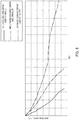
- FIG. 5 is a graph illustrating a time variation in the discharge capacity of the same storage battery charged and discharged repeatedly with a predetermined current amount. Respective three graph lines in FIG. 5 indicate the cases of high, middle, and low charge/discharge currents.
- the storage battery deteriorates and gradually decreases the discharge capacity (also referred to as a battery capacity) by repeating charge and discharge.
- the magnitude of a charge/discharge current for the storage battery i.e., the severity of use of the storage battery also varies the rate of deteriorating the storage battery. For example, a higher charge/discharge current increases the rate of the deterioration, and a lower charge/discharge current decreases the rate of the deterioration.
- the graph line for the high charge/discharge current in FIG. 5 indicates an example case used for a vehicle.
- Storage battery B of vehicle 100 outputs a large current in the case of running, and rapidly charges in the case of charging. Therefore, the use conditions for the storage battery in vehicle 100 are very severe in comparison with the other facilities.
- vehicle 100 is required to have a high storage battery performance, the storage battery performance reaches the lower limit of the required performance of vehicle 100 at a stage at which the deterioration degree of the storage battery does not progress so much.
- the graph line for the middle charge/discharge current in FIG. 5 indicates an example case used for a house.
- Storage battery B in house 200 or building 300 charges and discharges relatively moderately. Furthermore, in house 200 or building 300, the installation space for storage battery B is large in comparison with vehicle 100, and many storage batteries can be used in parallel. Therefore, in house 200 or building 300, the use conditions required for storage battery B are moderate in comparison with vehicle 100. Moreover, since the use conditions are moderate, the storage battery performance required for house 200 or building 300 is low in comparison with that for vehicle 100.
- the graph line for the low charge/discharge current in FIG. 5 indicates an example case used for a factory.
- factory 400 storage battery B charges and discharges in a further planned and stable manner.
- the installation space for storage battery B is further large in comparison with house 200 and building 300, and an enormous number of storage batteries can be used in parallel. Therefore, the use conditions for storage battery B in factory 400 are moderate in comparison with the use conditions for house 200 and building 300.
- the use conditions are moderate, the storage battery performance required for factory 400 is low in comparison with those for house 200 and building 300.
- the progression degree of deterioration is large in the storage battery used in vehicle 100, and decreases in the storage batteries used in house 200 (or building 300) and factory 400 in this order.
- the storage battery performance required for each application is the highest in vehicle 100, and decreases in the order of house 200 (or building 300) and factory 400.
- FIGS. 6A to 6C are graphs illustrating changes in deterioration curves in the case of relocation use of the storage battery.
- FIGS. 6A to 6C illustrate deterioration curves of storage batteries when a storage battery used for a certain period in a vehicle continues being used in the vehicle and when the storage battery used for the certain period is relocated to and used in a house or a factory, as an example.
- the deterioration curve of a storage battery variously changes depending on to which facility the storage battery is relocated for use and depending on when the storage battery is relocated. Moreover, assuming that the time point of the storage battery performance reaching the lower limit of the performance required for each facility is defined as a storage battery life, as can be seen from comparison in FIGS. 6A to 6C , the relocation use of a storage battery can lead to a longer storage battery life of the storage battery.
- FIG. 7 is a configuration diagram illustrating the details of storage battery B.
- Storage battery B as an object to be provided in a system of the present embodiment is composed of, for example, a lithium ion secondary battery.
- Storage battery B is provided by being packaged in a form of battery pack BP which can readily be mounted on each facility.
- battery pack BP includes a plurality of battery modules BM bundled in order to provide predetermined output and capacity.
- each battery module BM has a plurality of battery cells BC mounted therein.
- the collection and management of the battery information and the relocation use of the storage battery described above can be performed in units of battery packs BP, and also in units of battery modules BM or in units of battery cells BC.
- FIG. 8 is a flow chart illustrating the procedure of the storage battery deterioration prediction process.
- FIG. 9 is an explanatory diagram illustrating the various relocation models subject to deterioration prediction.
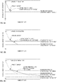
- FIGS. 10A to 10C are graphs illustrating the outline of the deterioration prediction curves of the storage battery in one relocation model.
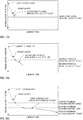
- FIGS. 11A to 11C are graphs illustrating the outline of the deterioration prediction curves of the storage battery in another relocation model.
- in-use battery deterioration prediction section 12 starts this storage battery deterioration prediction process. If the process starts, in-use battery deterioration prediction section 12 first reads in-use battery information from the in-use battery information storing section in step S11.
- step S12 in-use battery deterioration prediction section 12 sequentially selectively sets one relocation model for relocating a storage battery in the plurality of facilities from among the various relocation models.
- the various relocation models include a plurality of relocation patterns in which a storage battery is first used for vehicle 100 having severe use conditions and is then relocated to house 200, building 300, or factory 400 in order of the gradually loosened use conditions.
- the various relocation models also include relocation patterns involving the skip of one or more of house 200, building 300, and factory 400.
- the various relocation models also include patterns based on changing storage battery relocation time.
- the relocation models in FIGS. 9A to 9M have patterns in which a storage battery is relocated when the storage battery performance reaches the lower limit of the required performance for the facility using the storage battery.
- the relocation model in FIG. 9Q has a pattern in which a storage battery is relocated a little earlier (for example, a storage battery is relocated when the storage battery performance reaches a higher level by a predetermined amount than the lower limit of the required performance).
- the various relocation models also include patterns in which a relocation destination is set to another house 200, another building 300, or another factory 400 in the same category. Even in a facility in the same category (for example, house), a storage battery is severely utilized in some place and less severely utilized in another place, and the progression degree of deterioration is not necessarily the same.
- the relocation model in FIG. 9M involves relocation destinations changed independently.
- a facility model may be prepared so as to have a standard progression degree of deterioration
- a plurality of facility models may be prepared so as to have progression degrees of deterioration shifted from the standard degree at a plurality of levels, and these facility models may be combined to thereby prepare relocation models.
- step S13 in-use battery deterioration prediction section 12 predicts deterioration of the storage battery according to the relocation model set in step S12.
- the graphs in FIGS. 10A to 10C illustrate the case of a relocation model in which a storage battery used in vehicle 100 is used down to the lower limit of the required performance in each facility and is sequentially relocated to house 200 and then factory 400.
- in-use battery deterioration prediction section 12 predicts the deterioration prediction curve in vehicle 100 in FIG. 10A , for example, from the time transition data of the deterioration state (SOH) in the in-use battery information.
- in-use battery deterioration prediction section 12 can calculate a deterioration prediction curve from the data of the voltage log, the current log, and the temperature log in the in-use battery information, assuming that the same use situation continues.
- In-use battery deterioration prediction section 12 also calculates the deterioration prediction curve in house 200 in FIG. 10B , on the basis of the in-use battery information on another storage battery used in house 200. That is, a deterioration prediction curve is calculated from the data of the time transition data of the deterioration state (SOH) or the voltage log, the current log, and the temperature log included in the in-use battery information, assuming that the storage battery is used in the same situation.
- SOH time transition data of the deterioration state
- in-use battery deterioration prediction section 12 similarly calculates the deterioration prediction curve of factory 400 in FIG. 10C , on the basis of the in-use battery information on another storage battery used in factory 400.
- FIGS. 11A to 11C illustrate the case of a relocation model for sequentially relocating a storage battery presently used in vehicle 100 to house 200 and factory 400 in a stage involving a higher level by 10% than the lower limit of the required performance in each facility.
- in-use battery deterioration prediction section 12 calculates a deterioration prediction curve by setting the relocation time for a storage battery to the time when the storage battery performance reaches a higher value by a predetermined ratio than the lower limit of the required performance of each facility.
- In-use battery deterioration prediction section 12 also summarizes and calculates prediction of the progression degree of deterioration in each facility on the basis of the in-use battery information also in this relocation model similarly to the case of the relocation model in FIG. 10 .
- In-use battery deterioration prediction section 12 may also read the use-destination-information from use-destination-information storing section 23 to acquire information on the storage battery required performance in each facility.
- in-use battery deterioration prediction section 12 obtains the deterioration prediction curve of the storage battery for one relocation model, as illustrated in FIGS. 10A to 10C or 11A to 11C .
- step S14 in-use battery deterioration prediction section 12 accumulates the prediction result data representing the deterioration prediction curve obtained in step S13, into in-use battery deterioration prediction information storing section 22.
- in-use battery deterioration prediction section 12 then repeats the deterioration prediction and accumulation of the prediction result data for all the relocation patterns.
- in-use battery deterioration prediction section 12 also repeats the deterioration prediction and accumulation of the prediction result data for all the storage batteries.
- in-use battery deterioration prediction information storing section 22 accumulates therein the data of the deterioration curve in the case of the relocation use in the various relocation models for each storage battery.
- Collected-battery deterioration prediction section 16 predicts deterioration of the plurality of storage batteries B that would occur if they are continued to be kept in the collected-battery warehouse, and stores the data of the predicted deterioration curve in collected-battery deterioration prediction information storing section 25.
- This deterioration curve can be predicted and calculated from the time transition data of the deterioration state (SOH) or the data of the voltage log, the current log, and the temperature log stored in collected-battery information storing section 26, assuming that the deterioration progresses in the same situation.
- collected-battery deterioration prediction section 16 may also predict deterioration of a collected battery used by relocation, for example, to the house, the building, or the factory similarly to in-use battery deterioration prediction section 12, and may store the deterioration curve in collected-battery deterioration prediction information storing section 25.
- relocation determination section 14 Next, a relocation determination process performed by relocation determination section 14 will be described.
- FIG. 12 is a flow chart illustrating a procedure of the relocation determination process.
- FIG. 13 is a table illustrating determination requirements for relocating a storage battery.
- Relocation determination section 14 starts this relocation determination process in response to an instruction from an operator or at predetermined time interval. If the process is started, relocation determination section 14 first reads, in step S21, the data of predicted deterioration curve (also referred to as "deterioration prediction information") of each storage battery from in-use battery deterioration prediction information storing section 22, unused-battery deterioration prediction information storing section 24, and collected-battery deterioration prediction information storing section 25.
- deterioration prediction information also referred to as "deterioration prediction information”
- step S22 relocation determination section 14 reads use-destination-information from use-destination-information storing section 23.
- relocation determination section 14 determines the combination of the optimal relocation time and relocation destination (referred to as "relocation schedule") for each storage battery on the basis of the read data, by performing a calculation process (for example, optimization process) for comprehensively improving the sufficiency level of a plurality of predetermined determination requirements.
- the determination requirements for relocating storage batteries include, for example, a requirement of maintaining the contract electric power demand in each use destination, a requirement of maintaining the contract battery capacity in each use destination, and a requirement of setting relocation time in a way that makes the relocation time close to a time when the storage battery performance comes near the lower limit of the required performance in each facility.
- the determination requirements include, for example, a requirement of decreasing the number of new storage batteries to be supplied, a requirement of reducing a variation in the deterioration degrees of storage batteries simultaneously used in each facility, and a requirement of decreasing the reserved quantity of collected batteries.
- the determination requirements include a requirement of increasing the usage rate of the installation space for storage batteries in each facility.
- step S23 relocation determination section 14 performs a calculation process so as to better satisfy a requirement having a larger weighting factor, and determines the relocation schedule for each storage battery.
- the optimal storage battery which can be relocated from vehicle 100 to this house 200 is extracted to display this information on the relocation schedule.
- the optimal storage battery which can be relocated from the plurality of vehicles 100, houses 200, or buildings 300 to this factory 400 is extracted to display this information on the relocation schedule.
- information representing that the several storage batteries need to be replaced is displayed on the relocation schedule.
- the calculation process for comprehensively improving the sufficiency level of each determination requirement calculates a relocation schedule for storage batteries, the relocation schedule surely satisfying a requirement of maintaining the contract electric power demand in each use destination and a requirement of maintaining the contract battery capacity in each use destination.
- the relocation schedule for each storage battery is calculated to set relocation time in a way that makes the relocation time as close as possible to a time when a storage battery comes near the lower limit of the required performance in each facility and so as to minimize the number of new storage batteries to be supplied.
- the relocation schedule is calculated so as to minimize a variation in the deterioration degrees of storage batteries simultaneously used in each facility and so as to minimize the reserved quantity of collected batteries.
- the relocation schedule is calculated so as to relocate many progressively deteriorated storage batteries to a facility having a large installation space to increase the usage rate of the large installation space.
- the relocation schedule is calculated according to other determination requirements that are set variously.
- relocation determination section 14 distinguishes a relocation schedule involving relocation time close to the present time (for example, within one month from the present time) from among the determined relocation schedules. Then, if relocation determination section 14 finds a relocation schedule close to the present time, relocation determination section 14 outputs information on the relocation schedule to reporting section 15, in step S25. Thereby, the information on the relocation schedule is reported from reporting section 15 to an operator.
- the optimized relocation schedule which can better satisfy the determination requirements for relocation, for the storage battery is determined to display information on this relocation schedule for an operator.
- an operator Based on the information on this relocation schedule, an operator sets the schedule for relocation exchange for storage batteries in the plurality of vehicle 100, the plurality of house 200, the plurality of building 300, the plurality of factories 400, and collected-battery warehouse 500 in reality, and can advance a procedure of relocation of the storage batteries. That is, the operator and a worker, for example, report an exchange of a storage battery and perform exchange maintenance of a storage battery for a contractor according to the schedule for a relocation exchange.
- FIGS. 14A to 16 are explanatory diagrams of an example of repacking for relocating a storage battery.
- the storage battery may be relocated after repacking battery pack BP1 into other battery packs BP2 and BP3 according to conditions of a relocation destination or the battery state in battery pack BP1.
- a storage battery may be relocated in units of battery modules BM1.
- a storage battery may be relocated after such repacking that the deterioration degrees of a plurality of battery modules BMa and BMb in battery packs BP2 and BP3 are uniform. Then, battery packs BP2a and BP3a repacked so as to have uniform deterioration degrees may also be relocated.
- a storage battery may be relocated after replacing this battery cell BC1 with battery cell BC2 deteriorated in a similar degree to the other cells. Then, battery module BMla partially replaced may be relocated.
- relocation determination section 14 can also determine a relocation schedule in units of battery modules BM or in units of battery cells BC to thereby display information on combination for repacking battery packs and information on combination for uniforming non-uniform deterioration degrees.
- the in-use battery information representing the states of the plurality of storage batteries used in the plurality of facilities is collected in storage battery relocation assistance server 1. Furthermore, in-use battery deterioration prediction section 12 in storage battery relocation assistance server 1 predicts deterioration of storage batteries in the case of relocating the storage batteries in the plurality of facilities, on the basis of these information items. Therefore, this deterioration prediction result can assist determination of the optimal relocation time and relocation destination of a storage battery.
- relocation determination section 14 determines the combination of the optimal relocation time and relocation destination for each storage battery, on the basis of the deterioration prediction result in the case of relocating each storage battery among the plurality of facilities and the use-destination-information.
- Storage battery relocation assistance server 1 then outputs information on the relocation schedule of the determination result to the exterior. Therefore, on the basis of the information on this relocation schedule, an operator or a worker can set the schedule for relocating storage batteries in reality among the plurality of facilities and can cause the plurality of storage batteries to be relocated and used in the plurality of facilities. This can contribute to a comprehensive cost reduction for the life cycle from manufacturing to recycling of a storage battery.
- in-use battery state collection section 11 collects battery information through communication network 600.
- the battery information may also be collected after a delay of one week to several months, instead of real-time collecting of the battery information. Therefore, for example, the battery information may be accumulated in the facility during a predetermined period, and in-use battery state collection section 11 may collect this battery information through a storage medium, such as a record disk, a memory card, or a USB (Universal Serial Bus) memory.
- a storage medium having battery information written in the facility may be sent to the manager of storage battery relocation assistance server 1, and the manager may read battery information from this storage medium to send the battery information to in-use battery state collection section 11.
- storage battery relocation assistance server 1 may handle a plurality of kinds of storage batteries (for example, a lithium ion secondary battery and a nickel hydrogen secondary battery). Storage battery relocation assistance server 1 then performs a relocation schedule for relocating, to a facility using a first kind of storage battery, and using a second kind of storage battery.
- the embodiment has been described using specific examples for the contents of the in-use battery information, use-destination-information, and the determination requirement for relocation.
- the in-use battery information, the use-destination-information, and the determination requirement for relocation are not limited to the contents described in the embodiment.
- the relocation model which is set for predicting deterioration of a storage battery can also be modified appropriately by, for example, adding a relocation model having a collection period in midstream.
- the present invention can be utilized for the storage battery comprehensive management service for relocating and using a storage battery among the plurality of facilities.
Landscapes
- Engineering & Computer Science (AREA)
- Business, Economics & Management (AREA)
- Human Resources & Organizations (AREA)
- Economics (AREA)
- General Physics & Mathematics (AREA)
- Physics & Mathematics (AREA)
- Strategic Management (AREA)
- Manufacturing & Machinery (AREA)
- Chemical & Material Sciences (AREA)
- Chemical Kinetics & Catalysis (AREA)
- Electrochemistry (AREA)
- General Chemical & Material Sciences (AREA)
- Theoretical Computer Science (AREA)
- Marketing (AREA)
- General Business, Economics & Management (AREA)
- Tourism & Hospitality (AREA)
- Entrepreneurship & Innovation (AREA)
- Power Engineering (AREA)
- Sustainable Energy (AREA)
- Life Sciences & Earth Sciences (AREA)
- Sustainable Development (AREA)
- Transportation (AREA)
- Mechanical Engineering (AREA)
- Health & Medical Sciences (AREA)
- Quality & Reliability (AREA)
- Educational Administration (AREA)
- Operations Research (AREA)
- Game Theory and Decision Science (AREA)
- Development Economics (AREA)
- General Health & Medical Sciences (AREA)
- Primary Health Care (AREA)
- Public Health (AREA)
- Water Supply & Treatment (AREA)
- Secondary Cells (AREA)
- Charge And Discharge Circuits For Batteries Or The Like (AREA)
- Electric Propulsion And Braking For Vehicles (AREA)
- Management, Administration, Business Operations System, And Electronic Commerce (AREA)
Priority Applications (1)
| Application Number | Priority Date | Filing Date | Title |
|---|---|---|---|
| EP23152908.2A EP4191738A1 (en) | 2011-12-06 | 2012-12-04 | Storage battery transfer support device and storage batttery transfer support method |
Applications Claiming Priority (3)
| Application Number | Priority Date | Filing Date | Title |
|---|---|---|---|
| JP2011266774A JP5247874B2 (ja) | 2011-12-06 | 2011-12-06 | 蓄電池移転支援装置および蓄電池移転支援方法 |
| EP12856271.7A EP2790262A4 (en) | 2011-12-06 | 2012-12-04 | DEVICE AND METHOD FOR ASSISTING BATTERY TRANSFER |
| PCT/JP2012/007776 WO2013084481A1 (ja) | 2011-12-06 | 2012-12-04 | 蓄電池移転支援装置および蓄電池移転支援方法 |
Related Parent Applications (1)
| Application Number | Title | Priority Date | Filing Date |
|---|---|---|---|
| EP12856271.7A Division EP2790262A4 (en) | 2011-12-06 | 2012-12-04 | DEVICE AND METHOD FOR ASSISTING BATTERY TRANSFER |
Related Child Applications (1)
| Application Number | Title | Priority Date | Filing Date |
|---|---|---|---|
| EP23152908.2A Division EP4191738A1 (en) | 2011-12-06 | 2012-12-04 | Storage battery transfer support device and storage batttery transfer support method |
Publications (1)
| Publication Number | Publication Date |
|---|---|
| EP3537530A1 true EP3537530A1 (en) | 2019-09-11 |
Family
ID=48573871
Family Applications (3)
| Application Number | Title | Priority Date | Filing Date |
|---|---|---|---|
| EP19162203.4A Ceased EP3537530A1 (en) | 2011-12-06 | 2012-12-04 | Storage battery transfer support device and storage battery transfer support method |
| EP12856271.7A Ceased EP2790262A4 (en) | 2011-12-06 | 2012-12-04 | DEVICE AND METHOD FOR ASSISTING BATTERY TRANSFER |
| EP23152908.2A Withdrawn EP4191738A1 (en) | 2011-12-06 | 2012-12-04 | Storage battery transfer support device and storage batttery transfer support method |
Family Applications After (2)
| Application Number | Title | Priority Date | Filing Date |
|---|---|---|---|
| EP12856271.7A Ceased EP2790262A4 (en) | 2011-12-06 | 2012-12-04 | DEVICE AND METHOD FOR ASSISTING BATTERY TRANSFER |
| EP23152908.2A Withdrawn EP4191738A1 (en) | 2011-12-06 | 2012-12-04 | Storage battery transfer support device and storage batttery transfer support method |
Country Status (5)
| Country | Link |
|---|---|
| US (4) | US9555717B2 (zh) |
| EP (3) | EP3537530A1 (zh) |
| JP (2) | JP5247874B2 (zh) |
| CN (3) | CN106229565B (zh) |
| WO (1) | WO2013084481A1 (zh) |
Families Citing this family (70)
| Publication number | Priority date | Publication date | Assignee | Title |
|---|---|---|---|---|
| JP5247874B2 (ja) * | 2011-12-06 | 2013-07-24 | パナソニック株式会社 | 蓄電池移転支援装置および蓄電池移転支援方法 |
| US9551758B2 (en) | 2012-12-27 | 2017-01-24 | Duracell U.S. Operations, Inc. | Remote sensing of remaining battery capacity using on-battery circuitry |
| DE102013001066B4 (de) * | 2013-01-23 | 2022-01-20 | Brose Fahrzeugteile Se & Co. Kommanditgesellschaft, Bamberg | Kapazitiver Näherungssensor |
| US9478850B2 (en) | 2013-05-23 | 2016-10-25 | Duracell U.S. Operations, Inc. | Omni-directional antenna for a cylindrical body |
| US9726763B2 (en) * | 2013-06-21 | 2017-08-08 | Duracell U.S. Operations, Inc. | Systems and methods for remotely determining a battery characteristic |
| EP3026751B1 (en) * | 2013-07-25 | 2019-04-17 | Nissan Motor Co., Ltd | Battery secondary use management system, battery secondary use management device, and battery secondary use management method |
| JP5765375B2 (ja) * | 2013-07-25 | 2015-08-19 | トヨタ自動車株式会社 | 制御装置及び制御方法 |
| FR3010532B1 (fr) * | 2013-09-11 | 2017-06-09 | Commissariat Energie Atomique | Procede, dispositif et systeme d'estimation de l'etat de charge d'une batterie |
| JP6090143B2 (ja) * | 2013-12-13 | 2017-03-08 | トヨタ自動車株式会社 | 余寿命判定方法及びコスト算出方法 |
| US10088456B2 (en) * | 2014-03-31 | 2018-10-02 | Texas Instruments Incorporated | Scanning acoustic microscopy system and method |
| JP6149802B2 (ja) * | 2014-05-26 | 2017-06-21 | トヨタ自動車株式会社 | 余寿命推定方法 |
| US9882250B2 (en) | 2014-05-30 | 2018-01-30 | Duracell U.S. Operations, Inc. | Indicator circuit decoupled from a ground plane |
| WO2016052314A1 (ja) * | 2014-09-29 | 2016-04-07 | 三菱電機株式会社 | 絶縁劣化監視装置 |
| CN104325872A (zh) * | 2014-11-03 | 2015-02-04 | 宁德时代新能源科技有限公司 | 电池模组梯次利用系统及其使用方法 |
| CN104597406B (zh) * | 2014-12-30 | 2017-11-28 | 深圳市科陆电子科技股份有限公司 | 锂电池储能系统容量下降分析处理方法及分析处理装置 |
| US10228398B2 (en) * | 2015-04-02 | 2019-03-12 | Rosemount Aerospace Inc. | System and method for minimizing magnetic field effect on an isolated magnetometer |
| WO2016194082A1 (ja) * | 2015-05-29 | 2016-12-08 | 日産自動車株式会社 | バッテリ劣化度推定装置および推定方法 |
| KR101582825B1 (ko) * | 2015-06-30 | 2016-01-07 | 정현아 | 태양전지 모니터링장치 |
| US10502696B2 (en) * | 2015-07-28 | 2019-12-10 | Furuno Electric Co., Ltd. | Water vapor observing apparatus |
| CN105092907B (zh) * | 2015-08-28 | 2017-06-16 | 深圳市华星光电技术有限公司 | 信号转接装置及测试系统 |
| US10297875B2 (en) | 2015-09-01 | 2019-05-21 | Duracell U.S. Operations, Inc. | Battery including an on-cell indicator |
| KR102032071B1 (ko) * | 2015-09-02 | 2019-10-14 | 가부시키가이샤 히다치 하이테크놀로지즈 | 회로 검사 방법 및 시료 검사 장치 |
| KR102340973B1 (ko) * | 2015-09-18 | 2021-12-17 | 삼성전자주식회사 | 반도체 테스트 장치 및 방법과 데이터 분석 장치 |
| KR102527334B1 (ko) * | 2015-11-24 | 2023-05-02 | 삼성전자주식회사 | 배터리 관리 장치 및 방법 |
| KR20170060499A (ko) * | 2015-11-24 | 2017-06-01 | 현대자동차주식회사 | 배터리의 출력을 제어하는 방법 |
| EP3182169B1 (en) * | 2015-12-17 | 2018-12-05 | Mettler-Toledo Safeline Limited | Metal detection apparatus |
| US10176100B1 (en) * | 2015-12-21 | 2019-01-08 | Cadence Design Systems, Inc. | Cache coherency process |
| CN108701316B (zh) * | 2016-02-24 | 2023-09-29 | 松下知识产权经营株式会社 | 服务器装置及其控制方法 |
| CN105667464A (zh) * | 2016-03-18 | 2016-06-15 | 蔚来汽车有限公司 | 基于云存储的电动汽车换电系统和方法 |
| DE102016107528A1 (de) * | 2016-04-22 | 2017-10-26 | CTC cartech company GmbH | Verfahren und System zur Bewertung einer elektrochemischen Speichereinheit |
| CN107688107B (zh) * | 2016-08-04 | 2019-11-22 | 创意电子股份有限公司 | 测试装置与其探针连接器 |
| US10634730B2 (en) * | 2016-09-09 | 2020-04-28 | Inventus Holdings, Llc | Selective redistribution and replenishment of utility scale battery electric storage systems |
| US10197640B2 (en) * | 2016-09-30 | 2019-02-05 | International Business Machines Corporation | Carrier-resolved multiple dipole line magnet photo-hall system |
| US10818979B2 (en) | 2016-11-01 | 2020-10-27 | Duracell U.S. Operations, Inc. | Single sided reusable battery indicator |
| US10151802B2 (en) | 2016-11-01 | 2018-12-11 | Duracell U.S. Operations, Inc. | Reusable battery indicator with electrical lock and key |
| US11024891B2 (en) | 2016-11-01 | 2021-06-01 | Duracell U.S. Operations, Inc. | Reusable battery indicator with lock and key mechanism |
| US10608293B2 (en) | 2016-11-01 | 2020-03-31 | Duracell U.S. Operations, Inc. | Dual sided reusable battery indicator |
| US10483634B2 (en) | 2016-11-01 | 2019-11-19 | Duracell U.S. Operations, Inc. | Positive battery terminal antenna ground plane |
| JP7032061B2 (ja) * | 2017-05-31 | 2022-03-08 | 三菱重工業株式会社 | 調達支援装置、調達支援システム、調達支援方法、及びプログラム |
| KR101944751B1 (ko) | 2017-09-06 | 2019-02-01 | 주식회사 민테크 | 배터리 재사용 수명 진단 방법 |
| US10804688B2 (en) * | 2017-10-11 | 2020-10-13 | Littelfuse, Inc. | Arc detection based on variance of current flow |
| JP2018050457A (ja) * | 2017-10-26 | 2018-03-29 | 株式会社東芝 | 設備管理システム及び設備管理方法 |
| JP6874666B2 (ja) * | 2017-12-14 | 2021-05-19 | トヨタ自動車株式会社 | 電池情報処理装置、電池製造支援装置、組電池、電池情報処理方法、及び組電池の製造方法 |
| JP6911747B2 (ja) * | 2017-12-25 | 2021-07-28 | トヨタ自動車株式会社 | 電池情報処理装置、電池製造支援装置、組電池、電池情報処理方法、及び組電池の製造方法 |
| EP3780246A4 (en) * | 2018-03-26 | 2022-03-09 | Kyocera Corporation | CONTROL DEVICE, INFORMATION PROCESSING DEVICE AND ACCUMULATOR RECOVERY SYSTEM |
| JP2019184374A (ja) * | 2018-04-06 | 2019-10-24 | 株式会社日立製作所 | 蓄電システム |
| WO2019207852A1 (ja) * | 2018-04-23 | 2019-10-31 | パナソニックIpマネジメント株式会社 | データセンタのバックアップ用電源システム、バックアップ用電池ラック |
| JPWO2019235645A1 (ja) * | 2018-06-08 | 2021-06-17 | パナソニックIpマネジメント株式会社 | バッテリ管理システム及びバッテリ管理方法 |
| WO2020036984A1 (en) * | 2018-08-14 | 2020-02-20 | Batterycheck Llc | Power cell tracking and optimization system |
| DE112019004579T5 (de) * | 2018-09-13 | 2021-07-22 | Honda Motor Co., Ltd. | Anordnungsplanungsvorrichtung |
| JP7031615B2 (ja) * | 2019-01-16 | 2022-03-08 | 株式会社デンソー | 再利用可能な二次電池モジュールの供給設定システム |
| JP7048519B2 (ja) * | 2019-01-25 | 2022-04-05 | 本田技研工業株式会社 | 二次電池状態検知システム、二次電池状態検知装置および二次電池状態検知方法 |
| JP7088065B2 (ja) * | 2019-02-15 | 2022-06-21 | トヨタ自動車株式会社 | 車両管理システム |
| JP7147621B2 (ja) * | 2019-02-20 | 2022-10-05 | トヨタ自動車株式会社 | 充電制御装置及び方法 |
| JP7229062B2 (ja) * | 2019-03-27 | 2023-02-27 | 本田技研工業株式会社 | 寿命予測装置、寿命予測方法、及びプログラム |
| JP7178940B2 (ja) * | 2019-03-28 | 2022-11-28 | 本田技研工業株式会社 | 選定装置、選定方法、及びプログラム |
| JP7168521B2 (ja) * | 2019-05-09 | 2022-11-09 | 本田技研工業株式会社 | 決定装置、二次電池、決定方法およびプログラム |
| EP3990309A1 (en) * | 2019-06-28 | 2022-05-04 | Analog Devices International Unlimited Company | Battery fleet monitoring systems |
| JP6944209B2 (ja) * | 2020-02-05 | 2021-10-06 | 東洋システム株式会社 | 中古二次電池再利用システム |
| JP7443821B2 (ja) | 2020-02-28 | 2024-03-06 | 株式会社デンソー | 情報算出システム |
| WO2021207358A1 (en) * | 2020-04-09 | 2021-10-14 | Sensata Technologies, Inc. | Lifetime battery tracking using a wireless interface |
| JP7380440B2 (ja) * | 2020-06-18 | 2023-11-15 | トヨタ自動車株式会社 | 車両診断システムおよび車両 |
| US11977121B2 (en) | 2020-09-15 | 2024-05-07 | Analog Devices International Unlimited Company | Autonomous battery monitoring system |
| JP7363728B2 (ja) | 2020-09-25 | 2023-10-18 | トヨタ自動車株式会社 | 電気自動車の電池の管理装置 |
| US11837754B2 (en) | 2020-12-30 | 2023-12-05 | Duracell U.S. Operations, Inc. | Magnetic battery cell connection mechanism |
| WO2022210523A1 (ja) * | 2021-03-30 | 2022-10-06 | 本田技研工業株式会社 | 燃料電池の二次利用判定システム及び燃料電池の二次利用判定方法 |
| US11989073B2 (en) | 2021-08-05 | 2024-05-21 | Batterycheck Llc | System for facilitating edge analytics for power systems |
| WO2022187689A1 (en) * | 2022-03-04 | 2022-09-09 | Innopeak Technology, Inc. | Systems and methods for evaluating battery aging with data analytics |
| JP7415288B2 (ja) | 2022-03-25 | 2024-01-17 | いすゞ自動車株式会社 | バッテリ交換ステーション及びバッテリの温度管理方法 |
| WO2023234395A1 (ja) * | 2022-06-02 | 2023-12-07 | 株式会社村田製作所 | 電源装置、診断装置および診断方法 |
Citations (4)
| Publication number | Priority date | Publication date | Assignee | Title |
|---|---|---|---|---|
| JP2002140398A (ja) | 2000-11-01 | 2002-05-17 | Nec Corp | 自動車の給電サービスシステム |
| EP1786057A2 (en) * | 2005-11-14 | 2007-05-16 | Hitachi Vehicle Energy, Ltd. | Secondary battery and battery management |
| US20070134546A1 (en) * | 2005-10-18 | 2007-06-14 | Zenzo Hashimoto | Method of recycling a battery |
| US20090284226A1 (en) * | 2008-05-19 | 2009-11-19 | Panasonic Ev Energy Co., Ltd. | Method for exchanging rechargeable batteries |
Family Cites Families (13)
| Publication number | Priority date | Publication date | Assignee | Title |
|---|---|---|---|---|
| US6947881B1 (en) * | 1999-07-07 | 2005-09-20 | Honda Giken Kogyo Kabushiki Kaisha | Shared vehicle system and method with vehicle relocation |
| AU2001290370A1 (en) * | 2000-09-04 | 2002-03-22 | Invensys Energy Systems (Nz) Limited | Battery monitoring network |
| US8355965B2 (en) | 2005-02-22 | 2013-01-15 | Sharp Kabushiki Kaisha | Battery exchange service system and charging method therefor, and portable device |
| JP2007240182A (ja) * | 2006-03-06 | 2007-09-20 | Sony Corp | バッテリパックおよびその残容量情報供給装置 |
| CN100499312C (zh) * | 2006-05-12 | 2009-06-10 | 财团法人工业技术研究院 | 结合再生能源与无线通讯的供电及电池交换装置 |
| JP2008268082A (ja) * | 2007-04-23 | 2008-11-06 | Japan Radio Co Ltd | 携帯端末用バッテリの検査装置及び検査方法 |
| WO2009075109A1 (ja) | 2007-12-13 | 2009-06-18 | Panasonic Corporation | リチウム二次電池の寿命推定方法と劣化抑制方法、寿命推定器と劣化抑制器、それを用いた電池パック、充電器 |
| JP5509577B2 (ja) * | 2008-10-31 | 2014-06-04 | 日本電気株式会社 | 充電装置、管理装置、バッテリシステム、バッテリ管理方法、およびバッテリ管理プログラム |
| JP5310003B2 (ja) * | 2009-01-07 | 2013-10-09 | 新神戸電機株式会社 | 風力発電用鉛蓄電池制御システム |
| KR101398344B1 (ko) * | 2010-03-31 | 2014-05-23 | 도요타지도샤가부시키가이샤 | 중고 2차 전지의 선별 방법, 리빌트 전지 팩, 이것을 사용한 차량 및 전지 사용 기기, 및 리빌트 전지 팩의 제조 방법 |
| KR101132948B1 (ko) * | 2010-05-13 | 2012-04-05 | 엘에스산전 주식회사 | 전기자동차 충방전 시스템, 충방전 장치, 충방전 방법 |
| EP2458704A1 (en) * | 2010-11-30 | 2012-05-30 | Restore N.V. | Method and system for charging a fleet of batteries |
| JP5247874B2 (ja) * | 2011-12-06 | 2013-07-24 | パナソニック株式会社 | 蓄電池移転支援装置および蓄電池移転支援方法 |
-
2011
- 2011-12-06 JP JP2011266774A patent/JP5247874B2/ja active Active
-
2012
- 2012-12-04 EP EP19162203.4A patent/EP3537530A1/en not_active Ceased
- 2012-12-04 WO PCT/JP2012/007776 patent/WO2013084481A1/ja active Application Filing
- 2012-12-04 US US14/363,359 patent/US9555717B2/en active Active
- 2012-12-04 CN CN201610591265.2A patent/CN106229565B/zh active Active
- 2012-12-04 EP EP12856271.7A patent/EP2790262A4/en not_active Ceased
- 2012-12-04 EP EP23152908.2A patent/EP4191738A1/en not_active Withdrawn
- 2012-12-04 CN CN201610590288.1A patent/CN106207282A/zh active Pending
- 2012-12-04 CN CN201280059039.XA patent/CN104025367B/zh active Active
-
2013
- 2013-04-08 JP JP2013080316A patent/JP5842182B2/ja active Active
-
2016
- 2016-11-16 US US15/352,699 patent/US9748617B2/en active Active
-
2017
- 2017-07-25 US US15/658,812 patent/US10074882B2/en active Active
-
2018
- 2018-06-26 US US16/018,791 patent/US10312557B2/en active Active
Patent Citations (4)
| Publication number | Priority date | Publication date | Assignee | Title |
|---|---|---|---|---|
| JP2002140398A (ja) | 2000-11-01 | 2002-05-17 | Nec Corp | 自動車の給電サービスシステム |
| US20070134546A1 (en) * | 2005-10-18 | 2007-06-14 | Zenzo Hashimoto | Method of recycling a battery |
| EP1786057A2 (en) * | 2005-11-14 | 2007-05-16 | Hitachi Vehicle Energy, Ltd. | Secondary battery and battery management |
| US20090284226A1 (en) * | 2008-05-19 | 2009-11-19 | Panasonic Ev Energy Co., Ltd. | Method for exchanging rechargeable batteries |
Non-Patent Citations (6)
| Title |
|---|
| ANONYMOUS: "State of health - Wikipedia", 15 November 2011 (2011-11-15), XP055489135, Retrieved from the Internet <URL:https://en.wikipedia.org/w/index.php?title=State_of_health&oldid=460859654> [retrieved on 20180629] * |
| J NEUBAUER ET AL: "PHEV/EV Li-Ion Battery Second-Use Project (Presentation)", XXX, 1 April 2010 (2010-04-01), United States, XP055489583 * |
| JIE LIU ET AL: "An Adaptive Recurrent Neural Network for Remaining Useful Life Prediction of Lithium-ion Batteries", 1 October 2010 (2010-10-01), XP055489150, Retrieved from the Internet <URL:https://www.phmsociety.org/sites/phmsociety.org/files/phm_submission/2010/phmc_10_065.pdf> * |
| MARANO V ET AL: "Lithium-ion batteries life estimation for plug-in hybrid electric vehicles", VEHICLE POWER AND PROPULSION CONFERENCE, 2009. VPPC '09. IEEE, IEEE, PISCATAWAY, NJ, USA, 7 September 2009 (2009-09-07), pages 536 - 543, XP031637819, ISBN: 978-1-4244-2600-3 * |
| PETER WOLFS: "An economic assessment of second use lithium-ion batteries for grid support", UNIVERSITIES POWER ENGINEERING CONFERENCE (AUPEC), 2010 20TH AUSTRALASIAN, IEEE, 5 December 2010 (2010-12-05), pages 1 - 6, XP031913102, ISBN: 978-1-4244-8379-2 * |
| VILAYANUR V VISWANATHAN ET AL: "Second Use of Transportation Batteries: Maximizing the Value of Batteries for Transportation and Grid Services", IEEE TRANSACTIONS ON VEHICULAR TECHNOLOGY, IEEE SERVICE CENTER, PISCATAWAY, NJ, US, vol. 60, no. 7, 1 September 2011 (2011-09-01), pages 2963 - 2970, XP011359733, ISSN: 0018-9545, DOI: 10.1109/TVT.2011.2160378 * |
Also Published As
| Publication number | Publication date |
|---|---|
| CN104025367B (zh) | 2016-09-28 |
| CN106229565B (zh) | 2019-08-09 |
| EP4191738A1 (en) | 2023-06-07 |
| EP2790262A1 (en) | 2014-10-15 |
| EP2790262A4 (en) | 2015-08-19 |
| JP5247874B2 (ja) | 2013-07-24 |
| US10312557B2 (en) | 2019-06-04 |
| CN106207282A (zh) | 2016-12-07 |
| US20180301770A1 (en) | 2018-10-18 |
| US9555717B2 (en) | 2017-01-31 |
| US20140320144A1 (en) | 2014-10-30 |
| JP2013120640A (ja) | 2013-06-17 |
| WO2013084481A1 (ja) | 2013-06-13 |
| US9748617B2 (en) | 2017-08-29 |
| CN106229565A (zh) | 2016-12-14 |
| CN104025367A (zh) | 2014-09-03 |
| US20170324124A1 (en) | 2017-11-09 |
| US20170062883A1 (en) | 2017-03-02 |
| JP5842182B2 (ja) | 2016-01-13 |
| US10074882B2 (en) | 2018-09-11 |
| JP2013140631A (ja) | 2013-07-18 |
Similar Documents
| Publication | Publication Date | Title |
|---|---|---|
| US10312557B2 (en) | Storage battery relocation assistance apparatus and method | |
| EP2182575B1 (en) | Cartridge battery, management device, battery system, management method, and program | |
| CN105556786A (zh) | 蓄电池管理装置、蓄电池、蓄电池管理方法和程序 | |
| US9209629B2 (en) | Charge-discharge control device, charge-discharge control system, and computer program product | |
| WO2014196270A1 (ja) | 電池及び充電装置の管理システム、方法並びに充電装置 | |
| JP5887260B2 (ja) | 蓄電池の残量管理装置 | |
| EP3016237A1 (en) | Method for controlling charging power, system for controlling charging power, and program | |
| US20210339653A1 (en) | System for setting power supply of reusable secondary cell module | |
| CN105340150A (zh) | 充电状态管理方法、充电状态管理设备以及程序 | |
| Singh et al. | Benefit maximization and optimal scheduling of renewable energy sources integrated system considering the impact of energy storage device and Plug-in Electric vehicle load demand | |
| EP2871748A1 (en) | Charging system control device, program, and control method | |
| JP2012130106A (ja) | 蓄電装置の管理装置、蓄電装置の管理方法、及び電力供給システム | |
| JP6037678B2 (ja) | 蓄電池充放電制御装置及び蓄電池充放電制御システム | |
| CN114123430A (zh) | 一种多支路电池组供电的智能分组管理装置及控制方法 | |
| CN212783566U (zh) | 电池包群智能管理系统及电池包监控诊断装置 | |
| KR20210082297A (ko) | 공유형 배터리 교체 서비스 방법 | |
| Jung et al. | Lithium ion battery system in data centers | |
| Yousuf et al. | An In-Depth Exploration of Electric Vehicle Charging Station Infrastructure: A Comprehensive Review of Challenges, Mitigation Approaches, and Optimization Strategies | |
| WO2024062947A1 (ja) | 情報提供方法、管理システム及び充放電システム | |
| Iwanski | Prioritized sharing of charging energy in a multiple charging unit based batteries swapping station at communication fault | |
| Martel et al. | Preemptive degradation-induced battery replacement for hybrid electric vehicles in sustained optimal extended-range driving conditions | |
| Harasis et al. | Enabling Large-Scale Integration of Electric Bus Fleets in Harsh Environments: Possibilities, Potentials, and Challenges | |
| CN115347589A (zh) | 一种整包电池梯次利用系统和方法 | |
| CN115152119A (zh) | 蓄电池系统 |
Legal Events
| Date | Code | Title | Description |
|---|---|---|---|
| PUAI | Public reference made under article 153(3) epc to a published international application that has entered the european phase |
Free format text: ORIGINAL CODE: 0009012 |
|
| STAA | Information on the status of an ep patent application or granted ep patent |
Free format text: STATUS: THE APPLICATION HAS BEEN PUBLISHED |
|
| AC | Divisional application: reference to earlier application |
Ref document number: 2790262 Country of ref document: EP Kind code of ref document: P |
|
| AK | Designated contracting states |
Kind code of ref document: A1 Designated state(s): AL AT BE BG CH CY CZ DE DK EE ES FI FR GB GR HR HU IE IS IT LI LT LU LV MC MK MT NL NO PL PT RO RS SE SI SK SM TR |
|
| STAA | Information on the status of an ep patent application or granted ep patent |
Free format text: STATUS: REQUEST FOR EXAMINATION WAS MADE |
|
| 17P | Request for examination filed |
Effective date: 20200227 |
|
| RBV | Designated contracting states (corrected) |
Designated state(s): AL AT BE BG CH CY CZ DE DK EE ES FI FR GB GR HR HU IE IS IT LI LT LU LV MC MK MT NL NO PL PT RO RS SE SI SK SM TR |
|
| STAA | Information on the status of an ep patent application or granted ep patent |
Free format text: STATUS: EXAMINATION IS IN PROGRESS |
|
| 17Q | First examination report despatched |
Effective date: 20210301 |
|
| STAA | Information on the status of an ep patent application or granted ep patent |
Free format text: STATUS: THE APPLICATION HAS BEEN REFUSED |
|
| 18R | Application refused |
Effective date: 20221020 |