EP3536654A1 - Flurförderzeug mit einem fahrerdisplay - Google Patents
Flurförderzeug mit einem fahrerdisplay Download PDFInfo
- Publication number
- EP3536654A1 EP3536654A1 EP19160882.7A EP19160882A EP3536654A1 EP 3536654 A1 EP3536654 A1 EP 3536654A1 EP 19160882 A EP19160882 A EP 19160882A EP 3536654 A1 EP3536654 A1 EP 3536654A1
- Authority
- EP
- European Patent Office
- Prior art keywords
- function
- driver
- display
- truck according
- assigned
- Prior art date
- Legal status (The legal status is an assumption and is not a legal conclusion. Google has not performed a legal analysis and makes no representation as to the accuracy of the status listed.)
- Granted
Links
Images


Classifications
-
- G—PHYSICS
- G06—COMPUTING OR CALCULATING; COUNTING
- G06F—ELECTRIC DIGITAL DATA PROCESSING
- G06F3/00—Input arrangements for transferring data to be processed into a form capable of being handled by the computer; Output arrangements for transferring data from processing unit to output unit, e.g. interface arrangements
- G06F3/01—Input arrangements or combined input and output arrangements for interaction between user and computer
- G06F3/02—Input arrangements using manually operated switches, e.g. using keyboards or dials
- G06F3/023—Arrangements for converting discrete items of information into a coded form, e.g. arrangements for interpreting keyboard generated codes as alphanumeric codes, operand codes or instruction codes
- G06F3/0238—Programmable keyboards
-
- B—PERFORMING OPERATIONS; TRANSPORTING
- B60—VEHICLES IN GENERAL
- B60K—ARRANGEMENT OR MOUNTING OF PROPULSION UNITS OR OF TRANSMISSIONS IN VEHICLES; ARRANGEMENT OR MOUNTING OF PLURAL DIVERSE PRIME-MOVERS IN VEHICLES; AUXILIARY DRIVES FOR VEHICLES; INSTRUMENTATION OR DASHBOARDS FOR VEHICLES; ARRANGEMENTS IN CONNECTION WITH COOLING, AIR INTAKE, GAS EXHAUST OR FUEL SUPPLY OF PROPULSION UNITS IN VEHICLES
- B60K35/00—Instruments specially adapted for vehicles; Arrangement of instruments in or on vehicles
- B60K35/10—Input arrangements, i.e. from user to vehicle, associated with vehicle functions or specially adapted therefor
-
- B—PERFORMING OPERATIONS; TRANSPORTING
- B60—VEHICLES IN GENERAL
- B60K—ARRANGEMENT OR MOUNTING OF PROPULSION UNITS OR OF TRANSMISSIONS IN VEHICLES; ARRANGEMENT OR MOUNTING OF PLURAL DIVERSE PRIME-MOVERS IN VEHICLES; AUXILIARY DRIVES FOR VEHICLES; INSTRUMENTATION OR DASHBOARDS FOR VEHICLES; ARRANGEMENTS IN CONNECTION WITH COOLING, AIR INTAKE, GAS EXHAUST OR FUEL SUPPLY OF PROPULSION UNITS IN VEHICLES
- B60K35/00—Instruments specially adapted for vehicles; Arrangement of instruments in or on vehicles
- B60K35/20—Output arrangements, i.e. from vehicle to user, associated with vehicle functions or specially adapted therefor
- B60K35/21—Output arrangements, i.e. from vehicle to user, associated with vehicle functions or specially adapted therefor using visual output, e.g. blinking lights or matrix displays
- B60K35/22—Display screens
-
- B—PERFORMING OPERATIONS; TRANSPORTING
- B66—HOISTING; LIFTING; HAULING
- B66F—HOISTING, LIFTING, HAULING OR PUSHING, NOT OTHERWISE PROVIDED FOR, e.g. DEVICES WHICH APPLY A LIFTING OR PUSHING FORCE DIRECTLY TO THE SURFACE OF A LOAD
- B66F9/00—Devices for lifting or lowering bulky or heavy goods for loading or unloading purposes
- B66F9/06—Devices for lifting or lowering bulky or heavy goods for loading or unloading purposes movable, with their loads, on wheels or the like, e.g. fork-lift trucks
- B66F9/075—Constructional features or details
- B66F9/0759—Details of operating station, e.g. seats, levers, operator platforms, cabin suspension
-
- B—PERFORMING OPERATIONS; TRANSPORTING
- B66—HOISTING; LIFTING; HAULING
- B66F—HOISTING, LIFTING, HAULING OR PUSHING, NOT OTHERWISE PROVIDED FOR, e.g. DEVICES WHICH APPLY A LIFTING OR PUSHING FORCE DIRECTLY TO THE SURFACE OF A LOAD
- B66F9/00—Devices for lifting or lowering bulky or heavy goods for loading or unloading purposes
- B66F9/06—Devices for lifting or lowering bulky or heavy goods for loading or unloading purposes movable, with their loads, on wheels or the like, e.g. fork-lift trucks
- B66F9/075—Constructional features or details
- B66F9/20—Means for actuating or controlling masts, platforms, or forks
-
- B—PERFORMING OPERATIONS; TRANSPORTING
- B66—HOISTING; LIFTING; HAULING
- B66F—HOISTING, LIFTING, HAULING OR PUSHING, NOT OTHERWISE PROVIDED FOR, e.g. DEVICES WHICH APPLY A LIFTING OR PUSHING FORCE DIRECTLY TO THE SURFACE OF A LOAD
- B66F9/00—Devices for lifting or lowering bulky or heavy goods for loading or unloading purposes
- B66F9/06—Devices for lifting or lowering bulky or heavy goods for loading or unloading purposes movable, with their loads, on wheels or the like, e.g. fork-lift trucks
- B66F9/075—Constructional features or details
- B66F9/20—Means for actuating or controlling masts, platforms, or forks
- B66F9/24—Electrical devices or systems
-
- B—PERFORMING OPERATIONS; TRANSPORTING
- B60—VEHICLES IN GENERAL
- B60K—ARRANGEMENT OR MOUNTING OF PROPULSION UNITS OR OF TRANSMISSIONS IN VEHICLES; ARRANGEMENT OR MOUNTING OF PLURAL DIVERSE PRIME-MOVERS IN VEHICLES; AUXILIARY DRIVES FOR VEHICLES; INSTRUMENTATION OR DASHBOARDS FOR VEHICLES; ARRANGEMENTS IN CONNECTION WITH COOLING, AIR INTAKE, GAS EXHAUST OR FUEL SUPPLY OF PROPULSION UNITS IN VEHICLES
- B60K2360/00—Indexing scheme associated with groups B60K35/00 or B60K37/00 relating to details of instruments or dashboards
- B60K2360/122—Instrument input devices with reconfigurable control functions, e.g. reconfigurable menus
-
- B—PERFORMING OPERATIONS; TRANSPORTING
- B60—VEHICLES IN GENERAL
- B60K—ARRANGEMENT OR MOUNTING OF PROPULSION UNITS OR OF TRANSMISSIONS IN VEHICLES; ARRANGEMENT OR MOUNTING OF PLURAL DIVERSE PRIME-MOVERS IN VEHICLES; AUXILIARY DRIVES FOR VEHICLES; INSTRUMENTATION OR DASHBOARDS FOR VEHICLES; ARRANGEMENTS IN CONNECTION WITH COOLING, AIR INTAKE, GAS EXHAUST OR FUEL SUPPLY OF PROPULSION UNITS IN VEHICLES
- B60K2360/00—Indexing scheme associated with groups B60K35/00 or B60K37/00 relating to details of instruments or dashboards
- B60K2360/139—Clusters of instrument input devices
-
- B—PERFORMING OPERATIONS; TRANSPORTING
- B60—VEHICLES IN GENERAL
- B60Y—INDEXING SCHEME RELATING TO ASPECTS CROSS-CUTTING VEHICLE TECHNOLOGY
- B60Y2200/00—Type of vehicle
- B60Y2200/10—Road Vehicles
- B60Y2200/15—Fork lift trucks, Industrial trucks
Definitions
- the present invention relates to an industrial truck with a driver's display and at least one manually operable control element. Furthermore, a plurality of function keys is assigned to the manually operable control element spatially adjacent.
- a truck which is equipped with a control computer for controlling driving and working functions and with at least one display and control device.
- a Hubbignvorians is offered, in which a predetermined lifting height automatically approached and their achievement is displayed.
- a menu for selecting the desired lifting height is offered in the display and operating device, wherein this preselection can be changed by the operator.
- the favorite switching elements can be freely assigned by the operator with a lifting height.
- the invention has for its object to provide a truck with a driver's display, in which for ergonomic operation a variety of vehicle functions can be called easily and in an obvious manner.
- the truck according to the invention has a driver's display and at least one manually operable control element.
- a plurality of function keys are arranged spatially adjacent to the operating element, which may have, for example, a joystick or another steering / operating lever. The spatial proximity of the function keys to the control element allows ergonomic operation.
- a switchover key for the function keys is provided, upon actuation of which at least one of the function keys is assigned a secondary function.
- the secondary function can be called up for a pre-determined period of time after the shift key has been actuated by means of the corresponding function key. Alternatively to the predetermined time period, the Secondary function also be called permanently via the corresponding function key until the shift key is pressed again.
- the secondary function forms a driver-specific, freely programmable function which can be assigned by the driver himself as a secondary function of a function key without consulting a service technician or other assistance in accordance with his wishes and ideas.
- the truck according to the invention with its driver's display offers a number of possibilities here.
- the vehicle functions which can be conveniently called up via a function key, can be doubled. If each function key is assigned a secondary function, twice as many vehicle functions are available. Another particular advantage is that the secondary function can be selected driver-specific. If a first driver prefers to place the vehicle function B as a secondary function on a function key A, another driver can place the vehicle function C on the same function key. This results in pairs of vehicle functions (A, B), (B, C), which are defined by the driver as being dependent on the driver registered on the vehicle.
- the toggle button is designed to switch to a programming mode by actuating for more than a predetermined minimum duration.
- activating an operating function and actuating a function key to be assigned assigns the activated operating function as a secondary function. This is preferably done by this is activated by a function key after switching to the programming mode for occupancy of their secondary function. If an operating function is then selected and activated, for example by a selection via the driver's display, the function key is assigned this secondary function as a secondary function.
- the driver's display is equipped with one or more controls.
- the controls provided on the driver's display serve to display and select vehicle functions via the driver's display.
- the vehicle functions selected via the driver's display can be activated directly or assigned as a secondary function to one of the function keys.
- Important in the interpretation of the provided on the driver's display controls is that the selection of a vehicle function always works the same, regardless of whether the vehicle function should be turned on or activated or whether it should be selected as a secondary function for a function key. As a result, an intuitive operation and an intuitive assignment of driver-specific functions is particularly well possible.
- a storage unit and a driver registration unit are provided.
- a driver logs on to the driver logon unit his driver-specific secondary functions are loaded from the memory unit and, when the driver logs out, his driver-specific secondary functions are stored in the memory unit.
- the memory unit makes it possible to provide the secondary functions for a driver as needed and to assign them to a driver.
- the driver person is identified and the associated secondary functions are retrieved and provided.
- a further embodiment, which allows a highly intuitive operation is that upon actuation of the shift key the assigned secondary functions are displayed in the driver's display.
- the display of individual functions in the display is preferably carried out side by side in a meaningful order as the secondary functions are stored on the function keys. By repeating the secondary functions, they are recalled to the driver and thus memorized better. The intuitive operation is thereby facilitated.
- the secondary functions are preferably displayed only after the shift key has been pressed.
- the display of the secondary functions can be terminated by a renewed actuation of the shift key.
- the renewed actuation of the shift key also ends the possibility of triggering the secondary function by actuating the function key.
- the toggle button is spatially adjacent to the control element, such that preferably no wide encompassing or complete release of the control element must be done.
- Fig. 1 shows a reach truck 10 with two projecting arms 12 and a displaceably mounted on this mast base 14.
- the reach truck 10 has a driver's cab 16 with a driver's shelter roof 18 supported by four columns 20, 22.
- the formed as A-pillars columns 20 are on the side facing away from the radar arms 12 side, while the B-pillars 22 are provided on the side facing the mast side of the cab 16.
- a driver's seat 24 is arranged, which is oriented transversely to a vehicle longitudinal direction L. The transverse orientation of the driver's seat 24 causes the driver in a method of the reach truck along the vehicle longitudinal direction L moves laterally.
- the driver's seat opposite a steering unit 26 is provided, which is a steering wheel 28 (see. Fig. 3 ) and a driver's display 30 has.
- a steering wheel 28 see. Fig. 3
- a driver's display 30 has.
- an armrest 32 is provided on the side facing the mast base 14 on the side of the driver's seat 24.
- the armrest 32 serves to support the forearm of a driver seated in the driver's seat 24. With the right hand, the driver can grab an operating lever 34 and operate it.
- Fig. 2 shows a section Fig. 1 in which the operating lever 34 and the driver's display 30 can be seen.
- the operating lever 34 can be completely or partially encompassed. It is also possible to move the operating lever 34 only with the fingertips.
- a field 36 is arranged with function keys.
- the panel 36 is arranged so that it can also be operated with a lying on the armrest 32 forearm.
- the function keys in the field 36 for example, with the Forefinger or middle finger pressed, the hand remains on the operating lever, the thumb can also be used for the function keys. It is also possible to operate the function keys 36 with one hand, while further fingers actuate the operating lever 34.
- Fig. 3 shows the steering unit 26 in detail.
- the steering unit 26 has a steering wheel 28 which can be grasped and rotated, for example, via a knob 38.
- the knob 38 is in the left position at 9 o'clock, which facilitates operation with the help of the left hand.
- a driver registration unit 40 is provided in the steering unit.
- Fig. 3 shows three different driver registration units, wherein a keyboard 40a may be provided for entering a PIN.
- a card reader 40b may be provided which reads out a driver-specific identification card.
- a further option for a driver log-on unit is the illustrated chip reader 40c which, for example, reads out a personal driver chip card, whereby different techniques for the data exchange may be provided here, for example a transponder card, RFID or another near-field communication.
- One of the three driver registration units is inserted into the steering unit 26 and connected to the vehicle and its controller.
- the driver's display 30 has, as in Fig. 4 shown, a display 42, which may be formed, for example, as a touch-sensitive screen (touch screen).
- a display 42 which may be formed, for example, as a touch-sensitive screen (touch screen).
- six controls 44a - f are provided, which are designed as push buttons. With the help of the pushbuttons operating variables and vehicle functions can be displayed and selected in an obvious menu navigation. It can also be provided that the controls are occupied below the display 42 with fixed functions for the operation of the vehicle.
- the controls 44 on the steering unit 26 are arranged for the driver that they can not be operated simultaneously with the operating lever 34, but the operating lever 34 must be released to operate them (one-handed operation).
- Fig. 5 shows the field 36 with the function keys 46a to 46f, which are individually occupied with a fixed preconfigured function.
- the function key 46a aligns the load fork horizontally
- the function key 46b aligns a side slider with the center of the vehicle.
- the function key 46c triggers a weighing function on the vehicle.
- Function key 46e aligns the load handling device centrally between the load arms of a truck in order to avoid collisions during lowering.
- Function key 46f defines a crawl speed for the vehicle.
- Function key 46d is not defined in the illustrated embodiment.
- a shift key 48 is provided. The shift key 48 activates the secondary function for the function keys.
- the secondary function can be activated for a predetermined period of time, for example for a few seconds, by means of the shift key 48. During this period, the secondary functions are displayed in the display 42. As an alternative to the predetermined period of time, it is also possible for shift key 48 to activate the secondary functions until the shift key is pressed again.
- a light directed toward the load part can be provided as a secondary function for the horizontally oriented load fork with its function key 46a.
- the operator first actuates the function key 46a to horizontally align the forks and subsequently the shift key 48 to activate the illumination directed to the forks by re-activating the function key 46a.
- the secondary function can also be assigned to the function key 46f during crawl speed. Thus, it can be provided as a secondary function for the crawl speed that a all-round lighting is switched on the vehicle to make other participants aware of the crawl speed.
Landscapes
- Engineering & Computer Science (AREA)
- Transportation (AREA)
- Structural Engineering (AREA)
- Mechanical Engineering (AREA)
- Combustion & Propulsion (AREA)
- Chemical & Material Sciences (AREA)
- Civil Engineering (AREA)
- Geology (AREA)
- Life Sciences & Earth Sciences (AREA)
- General Engineering & Computer Science (AREA)
- Theoretical Computer Science (AREA)
- Human Computer Interaction (AREA)
- Physics & Mathematics (AREA)
- General Physics & Mathematics (AREA)
- Forklifts And Lifting Vehicles (AREA)
- Instrument Panels (AREA)
- Mechanical Control Devices (AREA)
Abstract
Description
- Die vorliegende Erfindung betrifft ein Flurförderzeug mit einem Fahrerdisplay und mindestens einem von Hand betätigbaren Bedienelement. Ferner ist eine Vielzahl von Funktionstasten dem von Hand betätigbaren Bedienelement räumlich benachbart zugeordnet.
- Flurförderzeuge mit einem Bedienplatz für den Fahrer, beispielsweise Schubmaststapler oder andere Gabelstapler, besitzen häufig ein Fahrerdisplay, auf dem dem Fahrer Informationen zum aktuellen Betriebszustand des Fahrzeugs und/oder zu auszuführenden Fahrzeugfunktionen angezeigt werden. Ferner ist es bekannt, das Flurförderzeug mit einer Reihe von Funktionstasten auszustatten, deren Betätigung direkt eine vorbestimmte Fahrzeugfunktion auslöst. Derartige Funktionstasten ermöglichen dem Fahrer, Funktionen an dem Fahrzeug komfortabel zu bedienen, ohne mit einem Umgreifen am oder Loslassen vom Bedienelement Funktionen an dem Fahrerdisplay auszuwählen und durchzuführen.
- Aus
EP 2 993 155 B1 ist ein Flurförderzeug bekannt geworden, das mit einem Steuerungsrechner zur Ansteuerung von Fahr- und Arbeitsfunktionen sowie mit mindestens einer Anzeige- und Bedienvorrichtung ausgestattet ist. Für eine einfache Bedienung des Flurförderzeugs wird eine Hubhöhenvorwahl angeboten, bei der eine vorbestimmte Hubhöhe automatisch angefahren und deren Erreichen angezeigt wird. Über einen Steuerungsrechner wird in der Anzeige- und Bedienvorrichtung ein Menü zur Auswahl der gewünschten Hubhöhe angeboten, wobei durch den Bediener diese Vorauswahl abgeändert werden kann. Ferner ist es ebenfalls bekannt, freiprogrammierbare Favoritenschaltelemente vorzusehen, die mit einer Hubhöhe belegt werden können, wobei durch eine einzige Betätigung der Favoritenschaltelemente diese Hubhöhe auswählbar ist. Die Favoritenschaltelemente sind durch den Bediener mit einer Hubhöhe frei belegbar. - Als nachteilig an der mitunter sehr komplexen Ansteuerung von Flurförderzeugen hat sich herausgestellt, dass fest vorgegebene Funktionstasten die relevante Anzahl an abzurufenden Bedien- und Fahrzeugfunktionen nicht ausreichend abbilden können, ohne dass eine unübersichtliche Vielzahl an fest vorgegebenen Funktionstasten notwendig wird.
- Der Erfindung liegt die Aufgabe zugrunde, ein Flurförderzeug mit einem Fahrerdisplay bereitzustellen, bei dem für eine ergonomische Bedienung eine Vielzahl von Fahrzeugfunktionen einfach und in sinnfälliger Weise aufgerufen werden können.
- Erfindungsgemäß wird die Aufgabe durch ein Flurförderzeug mit den Merkmalen aus Anspruch 1 gelöst. Vorteilhafte Ausgestaltungen bilden die Gegenstände der Unteransprüche.
- Das erfindungsgemäße Flurförderzeug besitzt ein Fahrerdisplay und mindestens ein von Hand betätigbares Bedienelement. Eine Vielzahl von Funktionstasten ist räumlich benachbart zu dem Bedienelement angeordnet, das beispielsweise einen Joy-Stick oder einen anderen Lenk-/Bedienhebel aufweisen kann. Die räumliche Nähe der Funktionstasten zu dem Bedienelement gestattet eine ergonomische Bedienung.
- Erfindungsgemäß ist eine Umschalttaste für die Funktionstasten vorgesehen, bei deren Betätigung mindestens einer der Funktionstasten eine Zweitfunktion zugeordnet ist. Bevorzugt kann die Zweitfunktion für eine vorgestimmte Zeitspanne nach Betätigung der Umschalttaste über die entsprechende Funktionstaste aufgerufen werden. Alternativ zu der vorbestimmten Zeitspanne kann die Zweitfunktion auch dauerhaft über die entsprechende Funktionstaste aufgerufen werden bis die Umschalttaste erneut betätigt wird. Vorteilhafterweise bildet die Zweitfunktion eine fahrerspezifisch frei programmierbare Funktion, die vom Fahrer selbst, ohne Hinzuziehen eines Servicetechnikers oder einer anderen Hilfe entsprechend seinen Wünschen und Vorstellungen als Zweitfunktion einer Funktionstaste zugeordnet werden kann. Das erfindungsgemäße Flurförderzeug mit seinem Fahrerdisplay bietet hier eine Reihe von Möglichkeiten. Einerseits können, ohne die Anzahl der zu bedienenden Funktionstasten zu vergrößern, die Fahrzeugfunktionen, die bequem über eine Funktionstaste aufrufbar sind, verdoppelt werden. Wenn jede Funktionstaste mit einer Zweitfunktion belegt ist, dann stehen doppelt so viele Fahrzeugfunktionen zur Verfügung. Ein weiterer besonderer Vorteil besteht darin, dass die Zweitfunktion fahrerspezifisch gewählt werden kann. Bevorzugt ein erster Fahrer die Fahrzeugfunktion B als Zweitfunktion auf einer Funktionstaste A zu legen, so kann ein anderer Fahrer die Fahrzeugfunktion C auf dieselbe Funktionstaste legen. So entstehen Paare von Fahrzeugfunktionen (A, B), (B, C), die fahrerspezifisch als abhängig von dem am Fahrzeug angemeldeten Fahrer definiert sind.
- In einer bevorzugten Weiterbildung ist die Umschalttaste ausgebildet, um durch eine Betätigung für mehr als eine vorbestimmte Mindestdauer in einen Programmiermodus zu wechseln. In dem Programmiermodus wird durch Aktivieren einer Betriebsfunktion und Betätigung einer zu belegenden Funktionstaste dieser die aktivierte Betriebsfunktion als Zweitfunktion zugewiesen. Bevorzugt erfolgt dies, indem nach einem Wechsel in den Programmiermodus durch Betätigen einer Funktionstaste, diese für eine Belegung ihrer Zweitfunktion aktiviert wird. Ist dann eine Betriebsfunktion ausgewählt und aktiviert, beispielsweise durch eine Auswahl über das Fahrerdisplay, so ist die Funktionstaste mit dieser Betriebsfunktion als Zweitfunktion belegt.
- In einer weiter bevorzugten Ausgestaltung ist das Fahrerdisplay mit einem oder mehreren Bedienelementen ausgestattet. Die an dem Fahrerdisplay vorgesehenen Bedienelementen dienen dazu, über das Fahrerdisplay Fahrzeugfunktionen darzustellen und auszuwählen. Die über das Fahrerdisplay ausgewählten Fahrzeugfunktionen können direkt aktiviert oder als Zweitfunktion einer der Funktionstasten zugewiesen werden. Wichtig an der Auslegung der am Fahrerdisplay vorgesehenen Bedienelemente ist, dass die Auswahl einer Fahrzeugfunktion stets gleich funktioniert, unabhängig davon, ob die Fahrzeugfunktion eingeschaltet oder aktiviert werden soll oder ob diese als Zweitfunktion für eine Funktionstaste ausgewählt werden soll. Hierdurch ist eine intuitive Bedienung und auch eine intuitive Zuweisung von fahrerspezifischen Funktionen besonders gut möglich.
- In einer bevorzugten Weiterbildung des erfindungsgemäßen Flurförderzeugs sind eine Speichereinheit und eine Fahreranmeldeeinheit vorgesehen. Hierbei ist vorgesehen, dass bei einem Anmelden eines Fahrers an der Fahreranmeldeeinheit seine fahrerspezifischen Zweitfunktionen aus der Speichereinheit geladen und bei einem Abmelden des Fahrers seine fahrerspezifischen Zweitfunktionen in der Speichereinheit gespeichert werden. Die Speichereinheit erlaubt es, die Zweitfunktionen für einen Fahrer jeweils bedarfsgerecht bereitzustellen und diese einer Fahrerperson zuzuordnen. Über die Fahreranmeldeeinheit wird die Fahrerperson identifiziert und die zugeordneten Zweitfunktionen werden abgerufen und bereitgestellt.
- Eine weitere Ausgestaltung, die eine im hohen Maße intuitive Bedienung gestattet, besteht darin, dass bei einer Betätigung der Umschalttaste die zugewiesenen Zweitfunktionen in dem Fahrerdisplay dargestellt werden. Die Anzeige der einzelnen Funktionen im Display erfolgt bevorzugt nebeneinander in einer sinnfälligen Reihenfolge wie die Zweitfunktionen auf den Funktionstasten abgelegt sind. Durch das erneute Darstellen der Zweitfunktionen werden diese dem Fahrer in Erinnerung gerufen und so besser memoriert. Auch die intuitive Bedienung wird hierdurch erleichtert. Um Verwirrungen zu vermeiden, werden die Zweitfunktionen bevorzugt nur dargestellt, nachdem die Umschalttaste betätigt wurde. Bevorzugt kann durch eine erneute Betätigung der Umschalttaste die Darstellung der Zweitfunktionen beendet werden. Bevorzugt endet mit der erneuten Betätigung der Umschalttaste auch die Möglichkeit die Zweitfunktion durch Betätigung der Funktionstaste auszulösen.
- In einer bevorzugten Weiterbildung der Erfindung ist die Umschalttaste räumlich benachbart zu dem Bedienelement angeordnet, derart, dass bevorzugt kein weites Umgreifen oder vollständiges Loslassen des Bedienelements erfolgen muss.
- Eine bevorzugte Ausgestaltung der Erfindung wird nachfolgend an einem beispielhaften Flurförderzeug erläutert. Es zeigen:
- Fig. 1
- eine perspektivische Ansicht von der Lastseite in die Fahrerkabine eines Schubmaststaplers, wobei der Hubmast nicht dargestellt ist,
- Fig. 2
- eine Detailansicht mit Lenkeinheit und Bedienelement,
- Fig. 3
- die Lenkeinheit mit dem Fahrerdisplay und mehreren beispielhaften Fahreranmeldeeinheiten als Zugangsmodule,
- Fig. 4
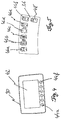
- das Fahrerdisplay mit seinen Bedientasten und
- Fig. 5
- die Funktionstasten mit einer zugehörigen Umschalttaste.
-
Fig. 1 zeigt einen Schubmaststapler 10 mit zwei vorstehenden Radarmen 12 und einem an diesen verschieblich gelagert Mastfuß 14. Zur besseren Übersicht ist der am Mastfuß 14 angeordnete Hubmast nicht dargestellt. Der Schubmaststapler 10 besitzt eine Fahrerkabine 16 mit einem Fahrerschutzdach 18, das von vier Säulen 20, 22 getragen ist. Die als A-Säulen ausgebildeten Säulen 20 liegen auf der von den Radarmen 12 fortweisenden Seite, während die B-Säulen 22 auf der zum Hubmast weisenden Seite der Fahrerkabine 16 vorgesehen sind. In der Fahrerkabine 16 ist ein Fahrersitz 24 angeordnet, der quer zu einer Fahrzeugslängsrichtung L orientiert ist. Die Querausrichtung des Fahrersitzes 24 bewirkt, dass der Fahrer bei einem Verfahren des Schubmaststaplers entlang der Fahrzeuglängsrichtung L sich seitlich bewegt. Dem Fahrersitz gegenüber ist eine Lenkeinheit 26 vorgesehen, die ein Lenkrad 28 (vgl.Fig. 3 ) sowie ein Fahrerdisplay 30 besitzt. InFig. 1 ist ferner zu erkennen, dass seitlich des Fahrersitzes 24 auf der zum Mastfuß 14 weisenden Seite eine Armstütze 32 vorgesehen ist. Die Armstütze 32 dient zum Abstützen des Unterarms eines in dem Fahrersitz 24 sitzenden Fahrers. Mit der rechten Hand kann der Fahrer einen Bedienhebel 34 ergreifen und diesen betätigen. -
Fig. 2 zeigt einen Ausschnitt ausFig. 1 , in dem der Bedienhebel 34 sowie das Fahrerdisplay 30 zu erkennen sind. Auf der Armstütze 32 liegt der rechte Unterarm der Bedienperson auf, wobei das Handgelenk zur besseren Beweglichkeit nicht aufliegt, sondern frei bleibt. Der Bedienhebel 34 kann ganz oder teilweise umgriffen werden. Auch ist es möglich, den Bedienhebel 34 nur mit den Fingerkuppen zu bewegen. Zwischen Armstütze 32 und Bedienhebel 34 ist ein Feld 36 mit Funktionstasten angeordnet. Das Feld 36 ist derart angeordnet, dass es auch mit einem auf der Armstütze 32 liegenden Unterarm bedient werden kann. Zur Bedienung werden die Funktionstasten in dem Feld 36 beispielsweise mit dem Zeigefinger oder dem Mittelfinger gedrückt, bleibt die Hand auf dem Bedienhebel liegen, kann auch der Daumen für die Funktionstasten benutzt werden. Auch ist es möglich, mit einer Hand die Funktionstasten 36 zu betätigen, während weitere Finger den Bedienhebel 34 betätigen. -
Fig. 3 zeigt die Lenkeinheit 26 im Detail. Die Lenkeinheit 26 besitzt ein Lenkrad 28, das beispielsweise über einen Knauf 38 ergriffen und gedreht werden kann. Bevorzugt befindet sich der Knauf 38 in der linken Position bei 9-Uhr, die eine Bedienung mit Hilfe der linken Hand erleichtert. Ferner ist in der Lenkeinheit eine Fahreranmeldeeinheit 40 vorgesehen.Fig. 3 zeigt drei verschiedene Fahreranmeldeeinheiten, wobei eine Tastatur 40a zur Eingabe einer PIN vorgesehen sein kann. Als Fahreranmeldeeinheit kann auch ein Kartenlesegerät 40b vorgesehen sein, das eine fahrerspezifische Identifikationskarte ausliest. Eine weitere Option für eine Fahreranmeldeeinheit ist das dargestellte Chiplesegerät 40c, das beispielsweise eine persönliche Fahrerchipkarte ausliest, wobei hier unterschiedliche Techniken für den Datenaustausch vorgesehen sein können, beispielsweise eine Transponderkarte, RFID oder eine andere Nahfeldkommunikation. - Eines der drei Fahreranmeldeeinheiten wird in die Lenkeinheit 26 eingesetzt und mit dem Fahrzeug und seiner Steuerung verbunden.
- Das Fahrerdisplay 30 besitzt, wie in
Fig. 4 dargestellt, eine Anzeige 42, die beispielsweise auch als berührungsempfindlicher Schirm (Touchscreen) ausgebildet sein kann. Unterhalb der Anzeige 42 sind sechs Bedienelemente 44a - f vorgesehen, die als Druckknöpfe ausgebildet sind. Mithilfe der Druckknöpfe können in einer sinnfälligen Menüführung Betriebsgrößen und Fahrzeugfunktionen angezeigt und ausgewählt werden. Auch kann vorgesehen sein, dass die Bedienelemente unterhalb der Anzeige 42 mit festen Funktionen für die Bedienung des Fahrzeugs belegt sind. Die Bedienelemente 44 an der Lenkeinheit 26 sind jedoch so für den Fahrer angeordnet, dass diese nicht gleichzeitig mit dem Bedienhebel 34 betätigt werden können, sondern der Bedienhebel 34 losgelassen werden muss, um diese zu betätigen (bei Einhandbedienung). -
Fig. 5 zeigt das Feld 36 mit den Funktionstasten 46a bis 46f, die einzeln mit einer fest vorkonfigurierten Funktion belegt sind. Die Funktionstaste 46a richtet beispielsweise die Lastgabel horizontal aus, die Funktionstaste 46b richtet einen Seitenschieber mittig am Fahrzeug aus. Über die Funktionstaste 46c wird eine Wiegefunktion am Fahrzeug ausgelöst, Funktionstaste 46e richtet das Lastaufnahmemittel mittig zwischen den Lastarmen eines Flurförderzeugs aus, um Kollisionen beim Absenken zu vermeiden. Funktionstaste 46f definiert eine Schleichfahrt für das Fahrzeug. Funktionstaste 46d ist in dem dargestellten Ausführungsbeispiel nicht definiert. Zusätzlich zu den Funktionstasten 46 ist eine Umschalttaste 48 vorgesehen. Die Umschalttaste 48 aktiviert die Zweitfunktion für die Funktionstasten. So kann beispielsweise über die Umschalttaste 48 die Zweitfunktion für eine vorbestimmte Zeitdauer, beispielsweise für einige Sekunden, aktiviert werden. In dieser Zeitspanne werden die Zweitfunktionen in der Anzeige 42 dargestellt. Alternative zu der vorbestimmten Zeitspanne ist es auch möglich, dass Umschalttaste 48 die Zweitfunktionen so lange aktiviert, bis die Umschalttatse erneut gedrückt wird. - Ist die Umschalttaste aktiviert, so kann beispielsweise als eine Zweitfunktion zur horizontal ausgerichteten Lastgabel mit ihrer Funktionstaste 46a eine auf das Lastteil gerichtete Beleuchtung vorgesehen sein. In diesem Fall betätigt die Bedienperson zunächst die Funktionstaste 46a, um die Lastgabel horizontal auszurichten und nachfolgend die Umschalttaste 48, um durch erneutes Betätigen der Funktionstaste 46a die auf die Lastgabeln gerichtete Beleuchtung zu aktivieren. Ähnlich sinnfällig kann die Zweitfunktion beispielsweise auch bei der Schleichfahrt mit der Funktionstaste 46f belegt sein. So kann als Zweitfunktion für die Schleichfahrt vorgesehen sein, dass eine Rundumbeleuchtung an dem Fahrzeug eingeschaltet wird, um andere Teilnehmer auf die Schleichfahrt aufmerksam zu machen.
- Bei dem Einsatz des erfindungsgemäßen Fahrzeugs können verschiedene Bediensituationen unterschieden werden:
- Betätigung der Zweitfunktion:
Wenn die Umschalttaste 48 nicht eingeschaltet ist, so kann diese durch einen Tastendruck auf das Tastenfeld eingeschaltet werden. Eine etwaige vorgesehene LED zeigt optisch die aktivierte Umschalttaste 48 an. Ist die Umschalttaste 48 eingeschaltet, so werden auf der Anzeige 42 die für die Funktionstasten 46 abgespeicherten Zweitfunktionen in Symbolen sinnfällig dargestellt. Die Positionierung der Symbole entspricht dabei der Reihenfolge der Funktionstasten 46. Wird nun eine der Funktionstasten 46 betätigt, so wird nicht die primär hinterlegte Funktion ausgeführt, sondern die hinterlegte Zweitfunktion gelangt zur Ausführung. Mit der Betätigung der Funktionstaste geht die Umschalttaste wieder in ihre Ausgangssituation, der nicht betätigten Umschalttaste zurück. - Belegen der Zweitfunktion:
Zur Belegung der Zweitfunktion wird die Umschalttaste für eine bestimmte Zeitdauer, beispielsweise für länger als 3 Sekunden, durchgehend gedrückt. Durch das Gedrückthalten der Umschalttaste fangen beispielsweise alle Funktionstasten 46 an zu blinken. Ist eine der Funktionstasten bereits mit einer Zweitfunktion belegt, so kann diese auch in der Anzeige 42 dargestellt werden. Von den Funktionstasten 46, sei es, dass diese noch nicht mit einer Zweitfunktion belegt sind oder bereits mit einer Zweitfunktion belegt sind, wird eine durch Betätigen der Funktionstaste ausgewählt. Nachfolgend kann bevorzugt über die Bedientasten 44 an der Anzeige 42 eine spezielle Funktion in dem Menü ausgewählt und für die ausgewählte Funktionstaste als Zweitfunktion aktiviert werden. Beispielsweise kann in einem Untermenü eine Rundumbeleuchtung für das Fahrzeug aktiviert werden. Wird diese Funktion in der Anzeige 42 aktiviert, so wird diese Funktion als Zweitfunktion der zuvor ausgewählten Funktionstaste abgelegt. Die Umschalttaste kehrt danach in ihre Ausgangslage zurück und der Belegungsvorgang ist abgeschlossen. Die Zweitfunktionen sind durch den Fahrer selbst programmierbare Funktionen, bei deren Auswahl und Festlegung der Fahrer keiner externen Unterstützung bedarf. - Personenspezifische Zweitfunktion:
Zur Betätigung des Flurförderzeugs identifiziert sich der Fahrer an einer Erkennungseinheit. Dies kann über eine PIN, eine Identifikationskarte oder einen Chip erfolgen. Mithilfe dieser persönlichen Anmeldung kann ein personenspezifisches Benutzerprofil aktiviert werden. Dies beinhaltet beispielsweise die Zweitfunktionen für die Funktionstasten. Ändert die Bedienperson, solange sie am Fahrzeug angemeldet ist, ihre Belegung der Zweitfunktion, so wird diese beim Abmelden oder Verlassen des Fahrzeugs gespeichert und steht beim nächsten Anmeldevorgang automatisch für den Fahrer wieder zur Verfügung. -
- 10
- Schubmaststapler
- 12
- Radarme
- 14
- Mastfuß
- 16
- Fahrerkabine
- 18
- Fahrerschutzdach
- 20
- A-Säulen
- 22
- B-Säulen
- 24
- Fahrersitz
- 26
- Lenkeinheit
- 28
- Lenkrad
- 30
- Fahrerdisplay
- 32
- Armstütze
- 34
- Bedienhebel
- 36
- Feld mit Funktionstasten
- 38
- Knauf
- 40
- Fahreranmeldeeinheit
- 40a
- Tastatur
- 40b
- Kartenlesegerät
- 40c
- Chiplesegerät
- 42
- Anzeige
- 44a-f
- Bedienelemente
- 46a-f
- Funktionstasten
- 48
- Umschalttaste
Claims (10)
- Flurförderzeug mit einem Fahrerdisplay (30) und mindestens einem von Hand betätigbaren Bedienelement (34), dem eine Vielzahl (36) von Funktionstasten (46) zugeordnet ist,
dadurch gekennzeichnet, dass
eine Umschalttaste (48) für die Funktionstasten (46) vorgesehen ist, bei deren Betätigung mindestens einer der Funktionstasten (46) eine jeweilige Zweitfunktion zugeordnet ist, wobei die Zweitfunktion eine vom Fahrer selbst programmierbare Funktion ist. - Flurförderzeug nach Anspruch 1, dadurch gekennzeichnet, dass die Umschalttaste (48) ausgebildet ist, durch eine Betätigung für mehr als eine vorbestimmte Mindestdauer in einen Programmiermodus zu wechseln, in dem durch Aktivieren einer Betriebsfunktion und Betätigen einer zu belegenden Funktionstaste (46), dieser die aktivierte Betriebsfunktion als Zweitfunktion zugewiesen werden kann.
- Flurförderzeug nach Anspruch 1 oder 2, dadurch gekennzeichnet, dass das Fahrerdisplay (30) mit einem oder mehreren Bedienelementen (44) ausgestattet ist, deren Betätigung eine über das Fahrerdisplay (30) ausgewählte Fahrzeugfunktion aktivieren oder als Zweitfunktion einer der Funktionstasten (46) zuweisen kann.
- Flurförderzeug nach einem der Ansprüche 1 bis 3, dadurch gekennzeichnet, dass eine Speichereinheit und eine Fahreranmeldeeinheit (40) vorgesehen sind, wobei beim Anmelden eines Fahrers an der Fahreranmeldeeinheit (40) seine fahrerspezifischen Zweitfunktionen aus der Speichereinheit geladen und bei einem Abmelden des Fahrers seine fahrerspezifischen Zweitfunktionen in der Speichereinheit gespeichert werden.
- Flurförderzeug nach einem der Ansprüche 1 bis 4, dadurch gekennzeichnet, dass bei einer Betätigung der Umschalttaste (48) die zugewiesenen Zweitfunktionen in dem Fahrerdisplay (30) dargestellt werden.
- Flurförderzeug nach Anspruch 5, dadurch gekennzeichnet, dass die zugewiesenen Zweitfunktionen mindestens für eine vorbestimmte Zeitspanne dargestellt werden.
- Flurförderzeug nach Anspruch 5 oder 6, dadurch gekennzeichnet, dass durch eine erneute Betätigung der Umschalttaste (48) die Darstellung der Zweitfunktionen beendet wird.
- Flurförderzeug nach einem der Ansprüche 1 bis 7, dadurch gekennzeichnet, dass durch eine erneute Betätigung der Umschalttaste (48) die Möglichkeit zum Abruf der Zweitfunktion beendet wird.
- Flurförderzeug nach einem der Ansprüche 1 bis 8, dadurch gekennzeichnet, dass die Umschalttaste (48) räumlich benachbart zu dem Bedienelement (34) angeordnet ist.
- Flurförderzeug nach einem der Ansprüche 1 bis 9, dadurch gekennzeichnet, dass bei einer Betätigung der Umschalttaste (48) die Zweitfunktionen für die Funktionstasten für eine vorbestimmte Zeitspanne aufrufbar sind.
Applications Claiming Priority (1)
| Application Number | Priority Date | Filing Date | Title |
|---|---|---|---|
| DE102018105410.6A DE102018105410A1 (de) | 2018-03-08 | 2018-03-08 | Flurförderzeug mit einem Fahrerdisplay |
Publications (2)
| Publication Number | Publication Date |
|---|---|
| EP3536654A1 true EP3536654A1 (de) | 2019-09-11 |
| EP3536654B1 EP3536654B1 (de) | 2022-12-28 |
Family
ID=65717819
Family Applications (1)
| Application Number | Title | Priority Date | Filing Date |
|---|---|---|---|
| EP19160882.7A Active EP3536654B1 (de) | 2018-03-08 | 2019-03-05 | Flurförderzeug mit einem fahrerdisplay |
Country Status (4)
| Country | Link |
|---|---|
| US (1) | US11347324B2 (de) |
| EP (1) | EP3536654B1 (de) |
| CN (1) | CN110240092B (de) |
| DE (1) | DE102018105410A1 (de) |
Cited By (1)
| Publication number | Priority date | Publication date | Assignee | Title |
|---|---|---|---|---|
| EP4122738A1 (de) * | 2021-07-20 | 2023-01-25 | AGCO International GmbH | Konfigurierbare benutzerschnittstelle |
Families Citing this family (4)
| Publication number | Priority date | Publication date | Assignee | Title |
|---|---|---|---|---|
| DE102018101538A1 (de) * | 2018-01-24 | 2019-07-25 | Jungheinrich Aktiengesellschaft | Flurförderzeug |
| DE102018105410A1 (de) * | 2018-03-08 | 2019-09-12 | Jungheinrich Aktiengesellschaft | Flurförderzeug mit einem Fahrerdisplay |
| SE544413C2 (en) * | 2020-01-24 | 2022-05-10 | Toyota Mat Handling Manufacturing Sweden Ab | Material handling vehicle and method for its operation by assigning a function to a favourite button on a touch screen |
| DE102024119167A1 (de) * | 2024-07-05 | 2026-01-08 | Jungheinrich Aktiengesellschaft | Flurförderzeug mit Multifunktionselement |
Citations (6)
| Publication number | Priority date | Publication date | Assignee | Title |
|---|---|---|---|---|
| DE102006059057A1 (de) * | 2006-12-14 | 2008-06-19 | Daimler Ag | Lenkrad für ein Fahrzeug mit zumindest einem Bedienelement |
| EP2338720A1 (de) * | 2009-12-24 | 2011-06-29 | Iveco S.p.A. | Bedien- und Konfigurationssystem für Fahrzeugsysteme, insbesondere für industrielle und Nutzfahrzeuge |
| EP2889255A1 (de) * | 2013-12-30 | 2015-07-01 | STILL GmbH | Flurförderzeug mit Anzeige- und Bedienvorrichtung |
| EP2889256A1 (de) * | 2013-12-30 | 2015-07-01 | STILL GmbH | Flurförderzeug mit Anzeige- und Bedienvorrichtung |
| EP2993155A1 (de) | 2014-09-08 | 2016-03-09 | STILL GmbH | Flurförderzeug mit assistenzfunktion |
| DE102015112201A1 (de) * | 2015-07-27 | 2017-02-02 | Claas Tractor Sas | Bedieneinheit für ein Arbeitsfahrzeug sowie Arbeitsfahrzeug |
Family Cites Families (28)
| Publication number | Priority date | Publication date | Assignee | Title |
|---|---|---|---|---|
| US5361644A (en) * | 1991-04-10 | 1994-11-08 | Wagner Fordertechnik Gmbh & Co. Kg | Combination control grip for two-hand operation or guided-surface industrial trucks |
| IT1269440B (it) * | 1994-01-19 | 1997-04-01 | Fita Om Carrelli Elevatori S P | Carrello elevatore a motorizzazione elettrica |
| DE19742657A1 (de) * | 1997-09-26 | 1999-04-01 | Bosch Gmbh Robert | Wischvorrichtung |
| US7265745B1 (en) * | 2000-04-27 | 2007-09-04 | Intel Corporation | Compact alphanumeric keyboard |
| US20060031465A1 (en) * | 2004-05-26 | 2006-02-09 | Motorola, Inc. | Method and system of arranging configurable options in a user interface |
| US8161404B2 (en) * | 2004-08-26 | 2012-04-17 | Harman Becker Automotive Systems Gmbh | Vehicle multimedia system |
| US9098118B2 (en) * | 2004-10-20 | 2015-08-04 | Robert R. Kodama | Computer keyboard with pointer control |
| CN2898893Y (zh) * | 2006-03-15 | 2007-05-09 | 延锋伟世通汽车饰件系统有限公司 | 车内控制系统 |
| US9026284B2 (en) * | 2006-09-21 | 2015-05-05 | General Electric Company | Methods and systems for throttle control and coupling control for vehicles |
| US20080257651A1 (en) * | 2007-04-23 | 2008-10-23 | Williamson Joel L | Lift truck with productivity enhancing package including variable tilt and vertical masting |
| US9032620B2 (en) * | 2008-12-12 | 2015-05-19 | Nuovo Pignone S.P.A. | Method for moving and aligning heavy device |
| CN101995969A (zh) * | 2009-08-26 | 2011-03-30 | 捷致科技有限公司 | 具有按键功能延伸设计的鼠标 |
| CN102043468A (zh) | 2009-10-21 | 2011-05-04 | 捷致科技有限公司 | 键盘 |
| US20130275907A1 (en) * | 2010-10-14 | 2013-10-17 | University of Technology ,Sydney | Virtual keyboard |
| US9026343B2 (en) * | 2010-12-29 | 2015-05-05 | Paccar Inc | Systems and methods for improving the efficiency of a vehicle |
| US9348492B1 (en) * | 2011-04-22 | 2016-05-24 | Angel A. Penilla | Methods and systems for providing access to specific vehicle controls, functions, environment and applications to guests/passengers via personal mobile devices |
| DE102013100419A1 (de) * | 2013-01-16 | 2014-07-17 | Linde Material Handling Gmbh | Flurförderzeug mit Komfortfunktion |
| DE102013006412A1 (de) * | 2013-04-13 | 2014-10-16 | Jungheinrich Aktiengesellschaft | Flurförderzeug mit einer Steuereinheit |
| DE102014101674A1 (de) * | 2013-12-30 | 2015-07-02 | Still Gmbh | Flurförderzeug mit Anzeige- und Bedienvorrichtung |
| US9758116B2 (en) * | 2014-01-10 | 2017-09-12 | Sony Corporation | Apparatus and method for use in configuring an environment of an automobile |
| DE102014107082A1 (de) * | 2014-05-20 | 2015-11-26 | Jungheinrich Aktiengesellschaft | Flurförderzeug mit Rampenhubfunktion |
| US9311033B2 (en) * | 2014-08-07 | 2016-04-12 | Kabushiki Kaisha Toshiba | Image processing apparatus system for storing and retrieving setting information |
| US10152227B2 (en) * | 2014-08-26 | 2018-12-11 | International Business Machines Corporation | Free form user-designed single-handed touchscreen keyboard |
| KR101716218B1 (ko) * | 2015-11-10 | 2017-03-15 | 현대자동차주식회사 | 차량 및 그 제어방법 |
| CN107103447B (zh) * | 2016-02-23 | 2021-04-13 | 平安科技(深圳)有限公司 | 页面配置方法和装置 |
| US20180261091A1 (en) * | 2017-03-08 | 2018-09-13 | Cesar Hernandez-Urbina | Home and work navigation information in main radio display with immediate navigation access |
| CN206590835U (zh) * | 2017-03-21 | 2017-10-27 | 宁夏东匠自动化技术有限公司 | 小型机械取货车 |
| DE102018105410A1 (de) * | 2018-03-08 | 2019-09-12 | Jungheinrich Aktiengesellschaft | Flurförderzeug mit einem Fahrerdisplay |
-
2018
- 2018-03-08 DE DE102018105410.6A patent/DE102018105410A1/de active Pending
-
2019
- 2019-03-05 EP EP19160882.7A patent/EP3536654B1/de active Active
- 2019-03-08 US US16/296,839 patent/US11347324B2/en active Active
- 2019-03-08 CN CN201910174069.9A patent/CN110240092B/zh active Active
Patent Citations (6)
| Publication number | Priority date | Publication date | Assignee | Title |
|---|---|---|---|---|
| DE102006059057A1 (de) * | 2006-12-14 | 2008-06-19 | Daimler Ag | Lenkrad für ein Fahrzeug mit zumindest einem Bedienelement |
| EP2338720A1 (de) * | 2009-12-24 | 2011-06-29 | Iveco S.p.A. | Bedien- und Konfigurationssystem für Fahrzeugsysteme, insbesondere für industrielle und Nutzfahrzeuge |
| EP2889255A1 (de) * | 2013-12-30 | 2015-07-01 | STILL GmbH | Flurförderzeug mit Anzeige- und Bedienvorrichtung |
| EP2889256A1 (de) * | 2013-12-30 | 2015-07-01 | STILL GmbH | Flurförderzeug mit Anzeige- und Bedienvorrichtung |
| EP2993155A1 (de) | 2014-09-08 | 2016-03-09 | STILL GmbH | Flurförderzeug mit assistenzfunktion |
| DE102015112201A1 (de) * | 2015-07-27 | 2017-02-02 | Claas Tractor Sas | Bedieneinheit für ein Arbeitsfahrzeug sowie Arbeitsfahrzeug |
Cited By (1)
| Publication number | Priority date | Publication date | Assignee | Title |
|---|---|---|---|---|
| EP4122738A1 (de) * | 2021-07-20 | 2023-01-25 | AGCO International GmbH | Konfigurierbare benutzerschnittstelle |
Also Published As
| Publication number | Publication date |
|---|---|
| US20190278385A1 (en) | 2019-09-12 |
| DE102018105410A1 (de) | 2019-09-12 |
| CN110240092A (zh) | 2019-09-17 |
| EP3536654B1 (de) | 2022-12-28 |
| CN110240092B (zh) | 2023-04-28 |
| US11347324B2 (en) | 2022-05-31 |
Similar Documents
| Publication | Publication Date | Title |
|---|---|---|
| EP3536654B1 (de) | Flurförderzeug mit einem fahrerdisplay | |
| DE69601944T2 (de) | Einheit zum verstellen der lage von mindestens zwei gliedern eines kraftfahrzeuges | |
| EP2930049B1 (de) | Anwenderschnittstelle und Verfahren zur Anpassung einer Ansicht auf einer Anzeigeeinheit | |
| DE19605427B4 (de) | Bedienvorrichtung in Kraftfahrzeugen | |
| WO2018137787A1 (de) | Verfahren zum betreiben einer mensch-maschinen-schnittstelle sowie mensch-maschinen-schnittstelle | |
| EP1604942B1 (de) | Vorrichtung zur Unterstützung des Ein-und Ausstapelns bei einem Stapler | |
| DE19606467A1 (de) | Verfahren zum Betrieb einer Tastatur und Tastaturabdeckung zur Anwendung des Verfahrens | |
| DE102004058954B4 (de) | Multifunktions-Bedieneinrichtung für Kraftfahrzeuge | |
| DE102007023774A1 (de) | Flurförderzeug mit Hubhöhenvorwahl | |
| EP2889256B1 (de) | Flurförderzeug mit Anzeige- und Bedienvorrichtung | |
| DE10248993A1 (de) | Betätigungsvorrichtung für eine Kochmulde | |
| DE102004061420A1 (de) | Bediensystem für ein Fahrzeug | |
| EP2889255B1 (de) | Flurförderzeug mit Anzeige- und Bedienvorrichtung | |
| DE102009037401A1 (de) | Fahrzeug mit einer Bedieneinrichtung | |
| EP0284007A2 (de) | Dateneingabe an Druckmaschinen | |
| EP1080979B1 (de) | Verfahren zur Gerätebedienung in Kraftfahrzeugen | |
| WO2004005065A1 (de) | Programmierbares bedienelement | |
| DE202005021769U1 (de) | Lenkrad mit einer Schalteranordnung für ein Kraftfahrzeug | |
| DE4201469C2 (de) | Orts- oder Fernbedienungstastatur | |
| EP0446396B1 (de) | Einrichtung zur Befehlsgabe für programmierbare Gebäudesystemtechnik | |
| DE102005025301B4 (de) | Einrichtung zur manuellen Eingabe und Anzeige von Daten | |
| EP2015163B1 (de) | Verfahren zur Übergabe von Zeichen und Vorrichtung zum Ausüben solchen Verfahrens | |
| EP3801793B1 (de) | Gamepad | |
| EP2889254A1 (de) | Flurförderzeug mit Anzeige- und Bedienvorrichtung | |
| DE102005025887A1 (de) | Bedieneinrichtung für ein Kraftfahrzeug |
Legal Events
| Date | Code | Title | Description |
|---|---|---|---|
| PUAI | Public reference made under article 153(3) epc to a published international application that has entered the european phase |
Free format text: ORIGINAL CODE: 0009012 |
|
| STAA | Information on the status of an ep patent application or granted ep patent |
Free format text: STATUS: THE APPLICATION HAS BEEN PUBLISHED |
|
| AK | Designated contracting states |
Kind code of ref document: A1 Designated state(s): AL AT BE BG CH CY CZ DE DK EE ES FI FR GB GR HR HU IE IS IT LI LT LU LV MC MK MT NL NO PL PT RO RS SE SI SK SM TR |
|
| AX | Request for extension of the european patent |
Extension state: BA ME |
|
| STAA | Information on the status of an ep patent application or granted ep patent |
Free format text: STATUS: REQUEST FOR EXAMINATION WAS MADE |
|
| 17P | Request for examination filed |
Effective date: 20200115 |
|
| RBV | Designated contracting states (corrected) |
Designated state(s): AL AT BE BG CH CY CZ DE DK EE ES FI FR GB GR HR HU IE IS IT LI LT LU LV MC MK MT NL NO PL PT RO RS SE SI SK SM TR |
|
| RIC1 | Information provided on ipc code assigned before grant |
Ipc: B60K 35/00 20060101ALI20220728BHEP Ipc: B60K 37/06 20060101ALI20220728BHEP Ipc: B66F 9/20 20060101ALI20220728BHEP Ipc: G05G 9/047 20060101ALI20220728BHEP Ipc: B66F 9/24 20060101ALI20220728BHEP Ipc: B66F 9/075 20060101AFI20220728BHEP |
|
| GRAP | Despatch of communication of intention to grant a patent |
Free format text: ORIGINAL CODE: EPIDOSNIGR1 |
|
| STAA | Information on the status of an ep patent application or granted ep patent |
Free format text: STATUS: GRANT OF PATENT IS INTENDED |
|
| INTG | Intention to grant announced |
Effective date: 20220914 |
|
| GRAS | Grant fee paid |
Free format text: ORIGINAL CODE: EPIDOSNIGR3 |
|
| GRAA | (expected) grant |
Free format text: ORIGINAL CODE: 0009210 |
|
| STAA | Information on the status of an ep patent application or granted ep patent |
Free format text: STATUS: THE PATENT HAS BEEN GRANTED |
|
| AK | Designated contracting states |
Kind code of ref document: B1 Designated state(s): AL AT BE BG CH CY CZ DE DK EE ES FI FR GB GR HR HU IE IS IT LI LT LU LV MC MK MT NL NO PL PT RO RS SE SI SK SM TR |
|
| REG | Reference to a national code |
Ref country code: GB Ref legal event code: FG4D Free format text: NOT ENGLISH |
|
| REG | Reference to a national code |
Ref country code: CH Ref legal event code: EP |
|
| REG | Reference to a national code |
Ref country code: DE Ref legal event code: R096 Ref document number: 502019006601 Country of ref document: DE |
|
| REG | Reference to a national code |
Ref country code: AT Ref legal event code: REF Ref document number: 1540368 Country of ref document: AT Kind code of ref document: T Effective date: 20230115 |
|
| REG | Reference to a national code |
Ref country code: IE Ref legal event code: FG4D Free format text: LANGUAGE OF EP DOCUMENT: GERMAN |
|
| REG | Reference to a national code |
Ref country code: SE Ref legal event code: TRGR |
|
| REG | Reference to a national code |
Ref country code: LT Ref legal event code: MG9D |
|
| PG25 | Lapsed in a contracting state [announced via postgrant information from national office to epo] |
Ref country code: NO Free format text: LAPSE BECAUSE OF FAILURE TO SUBMIT A TRANSLATION OF THE DESCRIPTION OR TO PAY THE FEE WITHIN THE PRESCRIBED TIME-LIMIT Effective date: 20230328 Ref country code: LT Free format text: LAPSE BECAUSE OF FAILURE TO SUBMIT A TRANSLATION OF THE DESCRIPTION OR TO PAY THE FEE WITHIN THE PRESCRIBED TIME-LIMIT Effective date: 20221228 Ref country code: FI Free format text: LAPSE BECAUSE OF FAILURE TO SUBMIT A TRANSLATION OF THE DESCRIPTION OR TO PAY THE FEE WITHIN THE PRESCRIBED TIME-LIMIT Effective date: 20221228 |
|
| REG | Reference to a national code |
Ref country code: NL Ref legal event code: MP Effective date: 20221228 |
|
| PG25 | Lapsed in a contracting state [announced via postgrant information from national office to epo] |
Ref country code: RS Free format text: LAPSE BECAUSE OF FAILURE TO SUBMIT A TRANSLATION OF THE DESCRIPTION OR TO PAY THE FEE WITHIN THE PRESCRIBED TIME-LIMIT Effective date: 20221228 Ref country code: LV Free format text: LAPSE BECAUSE OF FAILURE TO SUBMIT A TRANSLATION OF THE DESCRIPTION OR TO PAY THE FEE WITHIN THE PRESCRIBED TIME-LIMIT Effective date: 20221228 Ref country code: HR Free format text: LAPSE BECAUSE OF FAILURE TO SUBMIT A TRANSLATION OF THE DESCRIPTION OR TO PAY THE FEE WITHIN THE PRESCRIBED TIME-LIMIT Effective date: 20221228 Ref country code: GR Free format text: LAPSE BECAUSE OF FAILURE TO SUBMIT A TRANSLATION OF THE DESCRIPTION OR TO PAY THE FEE WITHIN THE PRESCRIBED TIME-LIMIT Effective date: 20230329 |
|
| PG25 | Lapsed in a contracting state [announced via postgrant information from national office to epo] |
Ref country code: NL Free format text: LAPSE BECAUSE OF FAILURE TO SUBMIT A TRANSLATION OF THE DESCRIPTION OR TO PAY THE FEE WITHIN THE PRESCRIBED TIME-LIMIT Effective date: 20221228 |
|
| PG25 | Lapsed in a contracting state [announced via postgrant information from national office to epo] |
Ref country code: SM Free format text: LAPSE BECAUSE OF FAILURE TO SUBMIT A TRANSLATION OF THE DESCRIPTION OR TO PAY THE FEE WITHIN THE PRESCRIBED TIME-LIMIT Effective date: 20221228 Ref country code: RO Free format text: LAPSE BECAUSE OF FAILURE TO SUBMIT A TRANSLATION OF THE DESCRIPTION OR TO PAY THE FEE WITHIN THE PRESCRIBED TIME-LIMIT Effective date: 20221228 Ref country code: PT Free format text: LAPSE BECAUSE OF FAILURE TO SUBMIT A TRANSLATION OF THE DESCRIPTION OR TO PAY THE FEE WITHIN THE PRESCRIBED TIME-LIMIT Effective date: 20230428 Ref country code: ES Free format text: LAPSE BECAUSE OF FAILURE TO SUBMIT A TRANSLATION OF THE DESCRIPTION OR TO PAY THE FEE WITHIN THE PRESCRIBED TIME-LIMIT Effective date: 20221228 Ref country code: EE Free format text: LAPSE BECAUSE OF FAILURE TO SUBMIT A TRANSLATION OF THE DESCRIPTION OR TO PAY THE FEE WITHIN THE PRESCRIBED TIME-LIMIT Effective date: 20221228 |
|
| P01 | Opt-out of the competence of the unified patent court (upc) registered |
Effective date: 20230628 |
|
| PG25 | Lapsed in a contracting state [announced via postgrant information from national office to epo] |
Ref country code: SK Free format text: LAPSE BECAUSE OF FAILURE TO SUBMIT A TRANSLATION OF THE DESCRIPTION OR TO PAY THE FEE WITHIN THE PRESCRIBED TIME-LIMIT Effective date: 20221228 Ref country code: PL Free format text: LAPSE BECAUSE OF FAILURE TO SUBMIT A TRANSLATION OF THE DESCRIPTION OR TO PAY THE FEE WITHIN THE PRESCRIBED TIME-LIMIT Effective date: 20221228 Ref country code: IS Free format text: LAPSE BECAUSE OF FAILURE TO SUBMIT A TRANSLATION OF THE DESCRIPTION OR TO PAY THE FEE WITHIN THE PRESCRIBED TIME-LIMIT Effective date: 20230428 Ref country code: AL Free format text: LAPSE BECAUSE OF FAILURE TO SUBMIT A TRANSLATION OF THE DESCRIPTION OR TO PAY THE FEE WITHIN THE PRESCRIBED TIME-LIMIT Effective date: 20221228 |
|
| REG | Reference to a national code |
Ref country code: DE Ref legal event code: R097 Ref document number: 502019006601 Country of ref document: DE |
|
| PG25 | Lapsed in a contracting state [announced via postgrant information from national office to epo] |
Ref country code: MC Free format text: LAPSE BECAUSE OF FAILURE TO SUBMIT A TRANSLATION OF THE DESCRIPTION OR TO PAY THE FEE WITHIN THE PRESCRIBED TIME-LIMIT Effective date: 20221228 Ref country code: DK Free format text: LAPSE BECAUSE OF FAILURE TO SUBMIT A TRANSLATION OF THE DESCRIPTION OR TO PAY THE FEE WITHIN THE PRESCRIBED TIME-LIMIT Effective date: 20221228 |
|
| REG | Reference to a national code |
Ref country code: CH Ref legal event code: PL |
|
| PLBE | No opposition filed within time limit |
Free format text: ORIGINAL CODE: 0009261 |
|
| STAA | Information on the status of an ep patent application or granted ep patent |
Free format text: STATUS: NO OPPOSITION FILED WITHIN TIME LIMIT |
|
| GBPC | Gb: european patent ceased through non-payment of renewal fee |
Effective date: 20230328 |
|
| REG | Reference to a national code |
Ref country code: BE Ref legal event code: MM Effective date: 20230331 |
|
| 26N | No opposition filed |
Effective date: 20230929 |
|
| PG25 | Lapsed in a contracting state [announced via postgrant information from national office to epo] |
Ref country code: LU Free format text: LAPSE BECAUSE OF NON-PAYMENT OF DUE FEES Effective date: 20230305 |
|
| REG | Reference to a national code |
Ref country code: IE Ref legal event code: MM4A |
|
| PG25 | Lapsed in a contracting state [announced via postgrant information from national office to epo] |
Ref country code: GB Free format text: LAPSE BECAUSE OF NON-PAYMENT OF DUE FEES Effective date: 20230328 |
|
| PG25 | Lapsed in a contracting state [announced via postgrant information from national office to epo] |
Ref country code: SI Free format text: LAPSE BECAUSE OF FAILURE TO SUBMIT A TRANSLATION OF THE DESCRIPTION OR TO PAY THE FEE WITHIN THE PRESCRIBED TIME-LIMIT Effective date: 20221228 Ref country code: LI Free format text: LAPSE BECAUSE OF NON-PAYMENT OF DUE FEES Effective date: 20230331 Ref country code: IE Free format text: LAPSE BECAUSE OF NON-PAYMENT OF DUE FEES Effective date: 20230305 Ref country code: GB Free format text: LAPSE BECAUSE OF NON-PAYMENT OF DUE FEES Effective date: 20230328 Ref country code: CH Free format text: LAPSE BECAUSE OF NON-PAYMENT OF DUE FEES Effective date: 20230331 |
|
| PG25 | Lapsed in a contracting state [announced via postgrant information from national office to epo] |
Ref country code: BE Free format text: LAPSE BECAUSE OF NON-PAYMENT OF DUE FEES Effective date: 20230331 |
|
| PG25 | Lapsed in a contracting state [announced via postgrant information from national office to epo] |
Ref country code: BG Free format text: LAPSE BECAUSE OF FAILURE TO SUBMIT A TRANSLATION OF THE DESCRIPTION OR TO PAY THE FEE WITHIN THE PRESCRIBED TIME-LIMIT Effective date: 20221228 |
|
| PG25 | Lapsed in a contracting state [announced via postgrant information from national office to epo] |
Ref country code: BG Free format text: LAPSE BECAUSE OF FAILURE TO SUBMIT A TRANSLATION OF THE DESCRIPTION OR TO PAY THE FEE WITHIN THE PRESCRIBED TIME-LIMIT Effective date: 20221228 |
|
| REG | Reference to a national code |
Ref country code: AT Ref legal event code: MM01 Ref document number: 1540368 Country of ref document: AT Kind code of ref document: T Effective date: 20240305 |
|
| PG25 | Lapsed in a contracting state [announced via postgrant information from national office to epo] |
Ref country code: AT Free format text: LAPSE BECAUSE OF NON-PAYMENT OF DUE FEES Effective date: 20240305 |
|
| PG25 | Lapsed in a contracting state [announced via postgrant information from national office to epo] |
Ref country code: CY Free format text: LAPSE BECAUSE OF FAILURE TO SUBMIT A TRANSLATION OF THE DESCRIPTION OR TO PAY THE FEE WITHIN THE PRESCRIBED TIME-LIMIT; INVALID AB INITIO Effective date: 20190305 |
|
| PG25 | Lapsed in a contracting state [announced via postgrant information from national office to epo] |
Ref country code: HU Free format text: LAPSE BECAUSE OF FAILURE TO SUBMIT A TRANSLATION OF THE DESCRIPTION OR TO PAY THE FEE WITHIN THE PRESCRIBED TIME-LIMIT; INVALID AB INITIO Effective date: 20190305 |
|
| PG25 | Lapsed in a contracting state [announced via postgrant information from national office to epo] |
Ref country code: TR Free format text: LAPSE BECAUSE OF FAILURE TO SUBMIT A TRANSLATION OF THE DESCRIPTION OR TO PAY THE FEE WITHIN THE PRESCRIBED TIME-LIMIT Effective date: 20221228 |
|
| PGFP | Annual fee paid to national office [announced via postgrant information from national office to epo] |
Ref country code: SE Payment date: 20260323 Year of fee payment: 8 |
|
| PGFP | Annual fee paid to national office [announced via postgrant information from national office to epo] |
Ref country code: DE Payment date: 20260320 Year of fee payment: 8 |
|
| PGFP | Annual fee paid to national office [announced via postgrant information from national office to epo] |
Ref country code: AT Payment date: 20260410 Year of fee payment: 5 |
|
| PGFP | Annual fee paid to national office [announced via postgrant information from national office to epo] |
Ref country code: FR Payment date: 20260325 Year of fee payment: 8 |
|
| PGFP | Annual fee paid to national office [announced via postgrant information from national office to epo] |
Ref country code: CZ Payment date: 20260223 Year of fee payment: 8 |
|
| PGFP | Annual fee paid to national office [announced via postgrant information from national office to epo] |
Ref country code: IT Payment date: 20260331 Year of fee payment: 8 |