EP3536533A1 - Appareil d'affichage par projection de véhicule - Google Patents
Appareil d'affichage par projection de véhicule Download PDFInfo
- Publication number
- EP3536533A1 EP3536533A1 EP19160219.2A EP19160219A EP3536533A1 EP 3536533 A1 EP3536533 A1 EP 3536533A1 EP 19160219 A EP19160219 A EP 19160219A EP 3536533 A1 EP3536533 A1 EP 3536533A1
- Authority
- EP
- European Patent Office
- Prior art keywords
- display
- obstacle
- driver
- display contents
- contents
- Prior art date
- Legal status (The legal status is an assumption and is not a legal conclusion. Google has not performed a legal analysis and makes no representation as to the accuracy of the status listed.)
- Granted
Links
- 238000001514 detection method Methods 0.000 claims description 36
- 230000000007 visual effect Effects 0.000 description 42
- 238000000034 method Methods 0.000 description 17
- 210000001508 eye Anatomy 0.000 description 11
- 230000003190 augmentative effect Effects 0.000 description 7
- 210000005252 bulbus oculi Anatomy 0.000 description 7
- 239000013598 vector Substances 0.000 description 4
- 239000000470 constituent Substances 0.000 description 2
- 238000010586 diagram Methods 0.000 description 2
- 210000003128 head Anatomy 0.000 description 2
- QIVUCLWGARAQIO-OLIXTKCUSA-N (3s)-n-[(3s,5s,6r)-6-methyl-2-oxo-1-(2,2,2-trifluoroethyl)-5-(2,3,6-trifluorophenyl)piperidin-3-yl]-2-oxospiro[1h-pyrrolo[2,3-b]pyridine-3,6'-5,7-dihydrocyclopenta[b]pyridine]-3'-carboxamide Chemical compound C1([C@H]2[C@H](N(C(=O)[C@@H](NC(=O)C=3C=C4C[C@]5(CC4=NC=3)C3=CC=CN=C3NC5=O)C2)CC(F)(F)F)C)=C(F)C=CC(F)=C1F QIVUCLWGARAQIO-OLIXTKCUSA-N 0.000 description 1
- 206010039203 Road traffic accident Diseases 0.000 description 1
- 230000004397 blinking Effects 0.000 description 1
- 230000003111 delayed effect Effects 0.000 description 1
- 230000007613 environmental effect Effects 0.000 description 1
- 238000005286 illumination Methods 0.000 description 1
- 239000004973 liquid crystal related substance Substances 0.000 description 1
- 230000003287 optical effect Effects 0.000 description 1
Images


Classifications
-
- G—PHYSICS
- G02—OPTICS
- G02B—OPTICAL ELEMENTS, SYSTEMS OR APPARATUS
- G02B27/00—Optical systems or apparatus not provided for by any of the groups G02B1/00 - G02B26/00, G02B30/00
- G02B27/01—Head-up displays
- G02B27/0179—Display position adjusting means not related to the information to be displayed
-
- G—PHYSICS
- G02—OPTICS
- G02B—OPTICAL ELEMENTS, SYSTEMS OR APPARATUS
- G02B27/00—Optical systems or apparatus not provided for by any of the groups G02B1/00 - G02B26/00, G02B30/00
- G02B27/01—Head-up displays
- G02B27/0101—Head-up displays characterised by optical features
-
- B—PERFORMING OPERATIONS; TRANSPORTING
- B60—VEHICLES IN GENERAL
- B60K—ARRANGEMENT OR MOUNTING OF PROPULSION UNITS OR OF TRANSMISSIONS IN VEHICLES; ARRANGEMENT OR MOUNTING OF PLURAL DIVERSE PRIME-MOVERS IN VEHICLES; AUXILIARY DRIVES FOR VEHICLES; INSTRUMENTATION OR DASHBOARDS FOR VEHICLES; ARRANGEMENTS IN CONNECTION WITH COOLING, AIR INTAKE, GAS EXHAUST OR FUEL SUPPLY OF PROPULSION UNITS IN VEHICLES
- B60K35/00—Instruments specially adapted for vehicles; Arrangement of instruments in or on vehicles
- B60K35/20—Output arrangements, i.e. from vehicle to user, associated with vehicle functions or specially adapted therefor
- B60K35/21—Output arrangements, i.e. from vehicle to user, associated with vehicle functions or specially adapted therefor using visual output, e.g. blinking lights or matrix displays
- B60K35/23—Head-up displays [HUD]
-
- B—PERFORMING OPERATIONS; TRANSPORTING
- B60—VEHICLES IN GENERAL
- B60K—ARRANGEMENT OR MOUNTING OF PROPULSION UNITS OR OF TRANSMISSIONS IN VEHICLES; ARRANGEMENT OR MOUNTING OF PLURAL DIVERSE PRIME-MOVERS IN VEHICLES; AUXILIARY DRIVES FOR VEHICLES; INSTRUMENTATION OR DASHBOARDS FOR VEHICLES; ARRANGEMENTS IN CONNECTION WITH COOLING, AIR INTAKE, GAS EXHAUST OR FUEL SUPPLY OF PROPULSION UNITS IN VEHICLES
- B60K35/00—Instruments specially adapted for vehicles; Arrangement of instruments in or on vehicles
- B60K35/20—Output arrangements, i.e. from vehicle to user, associated with vehicle functions or specially adapted therefor
- B60K35/28—Output arrangements, i.e. from vehicle to user, associated with vehicle functions or specially adapted therefor characterised by the type of the output information, e.g. video entertainment or vehicle dynamics information; characterised by the purpose of the output information, e.g. for attracting the attention of the driver
- B60K35/285—Output arrangements, i.e. from vehicle to user, associated with vehicle functions or specially adapted therefor characterised by the type of the output information, e.g. video entertainment or vehicle dynamics information; characterised by the purpose of the output information, e.g. for attracting the attention of the driver for improving awareness by directing driver's gaze direction or eye points
-
- B—PERFORMING OPERATIONS; TRANSPORTING
- B60—VEHICLES IN GENERAL
- B60K—ARRANGEMENT OR MOUNTING OF PROPULSION UNITS OR OF TRANSMISSIONS IN VEHICLES; ARRANGEMENT OR MOUNTING OF PLURAL DIVERSE PRIME-MOVERS IN VEHICLES; AUXILIARY DRIVES FOR VEHICLES; INSTRUMENTATION OR DASHBOARDS FOR VEHICLES; ARRANGEMENTS IN CONNECTION WITH COOLING, AIR INTAKE, GAS EXHAUST OR FUEL SUPPLY OF PROPULSION UNITS IN VEHICLES
- B60K35/00—Instruments specially adapted for vehicles; Arrangement of instruments in or on vehicles
- B60K35/20—Output arrangements, i.e. from vehicle to user, associated with vehicle functions or specially adapted therefor
- B60K35/29—Instruments characterised by the way in which information is handled, e.g. showing information on plural displays or prioritising information according to driving conditions
-
- B—PERFORMING OPERATIONS; TRANSPORTING
- B60—VEHICLES IN GENERAL
- B60R—VEHICLES, VEHICLE FITTINGS, OR VEHICLE PARTS, NOT OTHERWISE PROVIDED FOR
- B60R1/00—Optical viewing arrangements; Real-time viewing arrangements for drivers or passengers using optical image capturing systems, e.g. cameras or video systems specially adapted for use in or on vehicles
- B60R1/20—Real-time viewing arrangements for drivers or passengers using optical image capturing systems, e.g. cameras or video systems specially adapted for use in or on vehicles
- B60R1/22—Real-time viewing arrangements for drivers or passengers using optical image capturing systems, e.g. cameras or video systems specially adapted for use in or on vehicles for viewing an area outside the vehicle, e.g. the exterior of the vehicle
- B60R1/23—Real-time viewing arrangements for drivers or passengers using optical image capturing systems, e.g. cameras or video systems specially adapted for use in or on vehicles for viewing an area outside the vehicle, e.g. the exterior of the vehicle with a predetermined field of view
- B60R1/24—Real-time viewing arrangements for drivers or passengers using optical image capturing systems, e.g. cameras or video systems specially adapted for use in or on vehicles for viewing an area outside the vehicle, e.g. the exterior of the vehicle with a predetermined field of view in front of the vehicle
-
- B—PERFORMING OPERATIONS; TRANSPORTING
- B60—VEHICLES IN GENERAL
- B60R—VEHICLES, VEHICLE FITTINGS, OR VEHICLE PARTS, NOT OTHERWISE PROVIDED FOR
- B60R1/00—Optical viewing arrangements; Real-time viewing arrangements for drivers or passengers using optical image capturing systems, e.g. cameras or video systems specially adapted for use in or on vehicles
- B60R1/20—Real-time viewing arrangements for drivers or passengers using optical image capturing systems, e.g. cameras or video systems specially adapted for use in or on vehicles
- B60R1/31—Real-time viewing arrangements for drivers or passengers using optical image capturing systems, e.g. cameras or video systems specially adapted for use in or on vehicles providing stereoscopic vision
-
- G—PHYSICS
- G02—OPTICS
- G02B—OPTICAL ELEMENTS, SYSTEMS OR APPARATUS
- G02B27/00—Optical systems or apparatus not provided for by any of the groups G02B1/00 - G02B26/00, G02B30/00
- G02B27/0093—Optical systems or apparatus not provided for by any of the groups G02B1/00 - G02B26/00, G02B30/00 with means for monitoring data relating to the user, e.g. head-tracking, eye-tracking
-
- G—PHYSICS
- G06—COMPUTING; CALCULATING OR COUNTING
- G06F—ELECTRIC DIGITAL DATA PROCESSING
- G06F3/00—Input arrangements for transferring data to be processed into a form capable of being handled by the computer; Output arrangements for transferring data from processing unit to output unit, e.g. interface arrangements
- G06F3/01—Input arrangements or combined input and output arrangements for interaction between user and computer
- G06F3/011—Arrangements for interaction with the human body, e.g. for user immersion in virtual reality
- G06F3/013—Eye tracking input arrangements
-
- G—PHYSICS
- G08—SIGNALLING
- G08G—TRAFFIC CONTROL SYSTEMS
- G08G1/00—Traffic control systems for road vehicles
- G08G1/16—Anti-collision systems
- G08G1/166—Anti-collision systems for active traffic, e.g. moving vehicles, pedestrians, bikes
-
- B—PERFORMING OPERATIONS; TRANSPORTING
- B60—VEHICLES IN GENERAL
- B60K—ARRANGEMENT OR MOUNTING OF PROPULSION UNITS OR OF TRANSMISSIONS IN VEHICLES; ARRANGEMENT OR MOUNTING OF PLURAL DIVERSE PRIME-MOVERS IN VEHICLES; AUXILIARY DRIVES FOR VEHICLES; INSTRUMENTATION OR DASHBOARDS FOR VEHICLES; ARRANGEMENTS IN CONNECTION WITH COOLING, AIR INTAKE, GAS EXHAUST OR FUEL SUPPLY OF PROPULSION UNITS IN VEHICLES
- B60K2360/00—Indexing scheme associated with groups B60K35/00 or B60K37/00 relating to details of instruments or dashboards
- B60K2360/16—Type of output information
- B60K2360/178—Warnings
-
- B—PERFORMING OPERATIONS; TRANSPORTING
- B60—VEHICLES IN GENERAL
- B60K—ARRANGEMENT OR MOUNTING OF PROPULSION UNITS OR OF TRANSMISSIONS IN VEHICLES; ARRANGEMENT OR MOUNTING OF PLURAL DIVERSE PRIME-MOVERS IN VEHICLES; AUXILIARY DRIVES FOR VEHICLES; INSTRUMENTATION OR DASHBOARDS FOR VEHICLES; ARRANGEMENTS IN CONNECTION WITH COOLING, AIR INTAKE, GAS EXHAUST OR FUEL SUPPLY OF PROPULSION UNITS IN VEHICLES
- B60K2360/00—Indexing scheme associated with groups B60K35/00 or B60K37/00 relating to details of instruments or dashboards
- B60K2360/16—Type of output information
- B60K2360/179—Distances to obstacles or vehicles
-
- B—PERFORMING OPERATIONS; TRANSPORTING
- B60—VEHICLES IN GENERAL
- B60K—ARRANGEMENT OR MOUNTING OF PROPULSION UNITS OR OF TRANSMISSIONS IN VEHICLES; ARRANGEMENT OR MOUNTING OF PLURAL DIVERSE PRIME-MOVERS IN VEHICLES; AUXILIARY DRIVES FOR VEHICLES; INSTRUMENTATION OR DASHBOARDS FOR VEHICLES; ARRANGEMENTS IN CONNECTION WITH COOLING, AIR INTAKE, GAS EXHAUST OR FUEL SUPPLY OF PROPULSION UNITS IN VEHICLES
- B60K2360/00—Indexing scheme associated with groups B60K35/00 or B60K37/00 relating to details of instruments or dashboards
- B60K2360/18—Information management
- B60K2360/186—Displaying information according to relevancy
-
- B—PERFORMING OPERATIONS; TRANSPORTING
- B60—VEHICLES IN GENERAL
- B60K—ARRANGEMENT OR MOUNTING OF PROPULSION UNITS OR OF TRANSMISSIONS IN VEHICLES; ARRANGEMENT OR MOUNTING OF PLURAL DIVERSE PRIME-MOVERS IN VEHICLES; AUXILIARY DRIVES FOR VEHICLES; INSTRUMENTATION OR DASHBOARDS FOR VEHICLES; ARRANGEMENTS IN CONNECTION WITH COOLING, AIR INTAKE, GAS EXHAUST OR FUEL SUPPLY OF PROPULSION UNITS IN VEHICLES
- B60K2360/00—Indexing scheme associated with groups B60K35/00 or B60K37/00 relating to details of instruments or dashboards
- B60K2360/18—Information management
- B60K2360/191—Highlight information
-
- B—PERFORMING OPERATIONS; TRANSPORTING
- B60—VEHICLES IN GENERAL
- B60K—ARRANGEMENT OR MOUNTING OF PROPULSION UNITS OR OF TRANSMISSIONS IN VEHICLES; ARRANGEMENT OR MOUNTING OF PLURAL DIVERSE PRIME-MOVERS IN VEHICLES; AUXILIARY DRIVES FOR VEHICLES; INSTRUMENTATION OR DASHBOARDS FOR VEHICLES; ARRANGEMENTS IN CONNECTION WITH COOLING, AIR INTAKE, GAS EXHAUST OR FUEL SUPPLY OF PROPULSION UNITS IN VEHICLES
- B60K2360/00—Indexing scheme associated with groups B60K35/00 or B60K37/00 relating to details of instruments or dashboards
- B60K2360/20—Optical features of instruments
- B60K2360/33—Illumination features
- B60K2360/334—Projection means
-
- B—PERFORMING OPERATIONS; TRANSPORTING
- B60—VEHICLES IN GENERAL
- B60K—ARRANGEMENT OR MOUNTING OF PROPULSION UNITS OR OF TRANSMISSIONS IN VEHICLES; ARRANGEMENT OR MOUNTING OF PLURAL DIVERSE PRIME-MOVERS IN VEHICLES; AUXILIARY DRIVES FOR VEHICLES; INSTRUMENTATION OR DASHBOARDS FOR VEHICLES; ARRANGEMENTS IN CONNECTION WITH COOLING, AIR INTAKE, GAS EXHAUST OR FUEL SUPPLY OF PROPULSION UNITS IN VEHICLES
- B60K2360/00—Indexing scheme associated with groups B60K35/00 or B60K37/00 relating to details of instruments or dashboards
- B60K2360/20—Optical features of instruments
- B60K2360/33—Illumination features
- B60K2360/347—Optical elements for superposition of display information
-
- B—PERFORMING OPERATIONS; TRANSPORTING
- B60—VEHICLES IN GENERAL
- B60R—VEHICLES, VEHICLE FITTINGS, OR VEHICLE PARTS, NOT OTHERWISE PROVIDED FOR
- B60R2300/00—Details of viewing arrangements using cameras and displays, specially adapted for use in a vehicle
- B60R2300/20—Details of viewing arrangements using cameras and displays, specially adapted for use in a vehicle characterised by the type of display used
- B60R2300/205—Details of viewing arrangements using cameras and displays, specially adapted for use in a vehicle characterised by the type of display used using a head-up display
-
- G—PHYSICS
- G02—OPTICS
- G02B—OPTICAL ELEMENTS, SYSTEMS OR APPARATUS
- G02B27/00—Optical systems or apparatus not provided for by any of the groups G02B1/00 - G02B26/00, G02B30/00
- G02B27/01—Head-up displays
- G02B27/0101—Head-up displays characterised by optical features
- G02B2027/0138—Head-up displays characterised by optical features comprising image capture systems, e.g. camera
-
- G—PHYSICS
- G02—OPTICS
- G02B—OPTICAL ELEMENTS, SYSTEMS OR APPARATUS
- G02B27/00—Optical systems or apparatus not provided for by any of the groups G02B1/00 - G02B26/00, G02B30/00
- G02B27/01—Head-up displays
- G02B27/0101—Head-up displays characterised by optical features
- G02B2027/014—Head-up displays characterised by optical features comprising information/image processing systems
-
- G—PHYSICS
- G02—OPTICS
- G02B—OPTICAL ELEMENTS, SYSTEMS OR APPARATUS
- G02B27/00—Optical systems or apparatus not provided for by any of the groups G02B1/00 - G02B26/00, G02B30/00
- G02B27/01—Head-up displays
- G02B27/0101—Head-up displays characterised by optical features
- G02B2027/0141—Head-up displays characterised by optical features characterised by the informative content of the display
-
- G—PHYSICS
- G02—OPTICS
- G02B—OPTICAL ELEMENTS, SYSTEMS OR APPARATUS
- G02B27/00—Optical systems or apparatus not provided for by any of the groups G02B1/00 - G02B26/00, G02B30/00
- G02B27/01—Head-up displays
- G02B27/0179—Display position adjusting means not related to the information to be displayed
- G02B2027/0181—Adaptation to the pilot/driver
-
- G—PHYSICS
- G02—OPTICS
- G02B—OPTICAL ELEMENTS, SYSTEMS OR APPARATUS
- G02B27/00—Optical systems or apparatus not provided for by any of the groups G02B1/00 - G02B26/00, G02B30/00
- G02B27/01—Head-up displays
- G02B27/0179—Display position adjusting means not related to the information to be displayed
- G02B2027/0187—Display position adjusting means not related to the information to be displayed slaved to motion of at least a part of the body of the user, e.g. head, eye
Definitions
- the present invention relates to a vehicular projection display apparatus for projecting visible information in or in the vicinity of the field of view of a driver while he or she is driving a vehicle.
- a head-up display may be used to display information that is necessary for the driver.
- visible information is projection-displayed as a virtual image that is visible to the driver through the windshield so as to be superimposed on a scene (a road etc.) in the field of view of the driver or be viewed in the vicinity of the scene.
- the driver can view, at the same as he or she views a scene indicating a road situation etc. that are necessary for driving, a virtual image displayed in the same field of view as the scene without the need for moving the viewing point to a large extent.
- Patent document 1 which relates to a drive assist information display apparatus, discloses a technique for increasing the visibility of an obstacle located outside a vehicle in the case where a head-up display or the like is used. More specifically, the drive assist information display apparatus is equipped with a control unit for displaying drive assist information on a display screen, an obstacle detection unit for detecting a position of an obstacle located outside a vehicle, and an eyeball detection unit for detecting a position of the eyeballs of a driver. The control unit changes the display position of drive assist information to a position that is not located on the straight line connecting the position of the eyeballs and the position of the obstacle on the basis of the detected positions of the eyeballs and the obstacle.
- an actually existing real image and a virtual image projected by the head-up display appear in the field of view of a driver so as to be superimposed on each other. It is therefore possible, by employing an AR (augmented reality) technique, to display the virtual image by the head-up display in such a manner that it is recognized visually by the driver as part of an augmented version of the real image.
- AR augmented reality
- a virtual image of an actually non-existent road sign, mark, or the like at a proper position with a proper size on the surface of a road or beside a road so that it is superimposed on real images as if it existed actually by correctly determining the display position of the virtual image in the three-dimensional space where the real images exist.
- This type of head-up display is called a superimposition-type head-up display or an AR-HUD.
- the line of sight of the driver may be moved while the driver is aware of only one of the two obstacles. This is another case that the safety of a drive is lowered. Furthermore, if only a displayed virtual image that is superimposed on an obstacle is moved to another position in the case where plural virtual images are displayed at different positions, the plural displayed virtual images may be arranged so as to be difficult to recognize visually as a whole set. The driver would feel this kind of display annoying.
- the present invention has been made in view of the above circumstances, and an object of the invention is therefore to provide a vehicular projection display apparatus that allows a driver to easily recognize an obstacle that has newly appeared or has been increased in the degree of importance and to suppress the probability that a driver feels displayed contents annoying.
- the invention provides vehicular projection display apparatus having features that are described below in the form of configurations (1) to (5):
- the display position adjusting unit relocates plural display contents when a new obstacle is detected, whereby a state is established that the driver can easily recognize the new obstacle detected. Furthermore, since the resulting display positions reflect the priority ranks assigned to the respective display contents, display contents having high priority ranks and those having low priority ranks can be relocated under different conditions. This makes it possible to prevent the driver from feeling displayed virtual images annoying while allowing the driver to recognize an obstacle more easily.
- the vehicular projection display apparatus having the aforementioned configuration (3), since display contents other than a particular display content, that is, display contents that relate to real images only weakly, are moved to positions close to the driver, a state is established that the driver can recognize these display contents more easily and hence is prevented from feeling their movements annoying. Furthermore, by displaying these display contents so as to be superimposed of real images except when they are relocated, stereoscopic display that is suitable for the real images, for example, can be made, which would be impressive to the driver.
- plural display contents can be relocated so as to reflect a change in a drive state.
- display contents can be relocated when their degrees of importance have increased as in a case that an obstacle has approached the vehicle suddenly after a long period when no such event occurred.
- Performing relocation only when it is detected that the degree of importance of each display content has increased by a prescribed value or more makes it possible to avoid frequent occurrence of relocation, and the driver is prevented from being annoyed by such an event.
- the vehicular projection display apparatus having the aforementioned configuration (5), even if a display position of a display content after the movement is not proper, the display content can be prevented from being superimposed on an obstacle region by moving it again. Lowering in the visibility of the obstacle can thus be avoided.
- the vehicular projection display apparatus allows a driver to easily recognize an obstacle that has newly appeared or has been increased in the degree of importance and to suppress the probability that a driver feels displayed contents annoying.
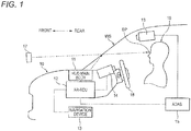
- Fig. 1 is a side view of a vehicle body 10 of a vehicle in which a vehicular projection display apparatus according to the embodiment of the invention is installed and is partially a block diagram outlining how its major constituent elements are laid out and connected to each other.
- the left side and the right side correspond to the front side and the rear side of the vehicle body 10, respectively.
- the vehicular projection display apparatus shown in Fig. 1 is equipped with a HUD main body 11, a superimposition drawing control unit (AR-ECU) 12, a navigation device 13, a line-of-sight detection device 14, an advanced driver assistance system (ADAS) 15, and an obstacle detection device 16.
- AR-ECU superimposition drawing control unit
- ADAS advanced driver assistance system
- the HUD main body 11 can project an image displayed on a two-dimensional screen of a liquid crystal display or the like onto the windshield WS using illumination light such as backlight.
- illumination light such as backlight.
- Light that is projected by the HUD main body 11 and forms an optical image on the windshield WS is reflected by the windshield WS or a combiner disposed in its vicinity and goes toward an eye point EP of a driver 19.
- a driver 19 can visually recognize the image projected by the HUD main body 11 as a virtual image 17 that is formed as if to exist in front of the windshield WS. Since the driver 19 views an outside scene such as a road surface through the windshield WS as real images, he or she can visually recognize, at the same time, these real images and the virtual image 17 projected by the HUD main body 11 in such a manner that the latter is superimposed on the former.
- the superimposition drawing control unit 12 is an electronic control unit having a function of generating various display contents to be projected by the HUD main body 11 and drawing them on a screen.
- the superimposition drawing control unit 12 employed in the embodiment also has a function of realizing augmented reality (AR). More specifically, the superimposition drawing control unit 12 controls the display position, the size, etc. of display contents to be projected as virtual images 17 by the HUD main body 11 so that the driver 19 can visually recognize them as if they existed in a three-dimensional real space. That is, the superimposition drawing control unit 12 successively determines a position and a size of each display content according to a variation of the situation so that they reflect the position of the eye point EP of the driver 19 and sets of coordinates of a scene etc. in the three-dimensional real space that can be visually recognized by the driver 19 actually whose eye point EP is located at that position.
- AR augmented reality
- the navigation device 13 provides precise map information and information representing a road situation around the self vehicle. More specifically, the navigation device 13 measures a position of the self vehicle using a GPS (global positioning system) receiver and acquires necessary information using the Intelligent Transport Systems (ITS).
- the Intelligent Transport Systems can provide information that is necessary to solve various road-traffic-related problems such as a traffic accident, a congestion, and an environmental measure by exchanging information between persons, roads, and vehicles.
- the line-of-sight detection device 14 has a function of acquiring information relating to a line-of-sight direction of the driver 19. More specifically, the line-of-sight detection device 14 can acquire information relating to a line-of-sight direction of the driver 19 by detecting a position of his or her face, positions of his or her eyeballs, directions of the eyeballs, etc. with a camera that is installed on an instrument panel in the vicinity of a steering wheel 18 and performing calculation.
- the advanced driver assistance system 15 has a function of recognizing an obstacle, positions on a road surface, etc. that relate to driving of the vehicle using the obstacle detection device 16 and various other sensors.
- the advanced driver assistance system 15 can detect various obstacles, positions and shapes of respective portions of a road on which the vehicle is running, positions of respective running lanes of the road, and other things by, for example, scanning a prescribed area ahead of the vehicle in its running direction.
- the obstacle detection device 16 which includes a vehicular stereoscopic camera for shooting, for example a scene ahead of the vehicle, can detect positions and distances of various obstacles that may influence driving of the vehicle such as a pedestrian around the vehicle and other vehicles on the basis of a video taken by the vehicular stereoscopic camera.
- Fig. 2 shows example images etc. in the front field of view of the driver 19 who is driving the vehicle.
- the X-axis direction is the left-right direction of the vehicle and the Y-axis direction is the top-bottom direction of the vehicle.
- the direction perpendicular to the paper surface of Fig. 2 and going away from the reader is the advancement direction of the vehicle, that is, the depth direction of the field of view (Z-axis direction).
- the detected obstacles D01 and D02 are a preceding vehicle and a pedestrian, respectively.
- a display prohibition region A0 which is a rectangular region surrounding the detected obstacle D01 is a region where display of a virtual image is prohibited to prevent an event that a virtual image displayed by the HUD main body 11 obstructs visual recognition of the detected obstacle D01.
- a display prohibition region A1 which is a rectangular region surrounding the detected obstacle D02 is a region that is assigned to prevent an event that a virtual image obstructs visual recognition of the detected obstacle D02.
- a display prohibition region such as the display prohibition regions A0 and A1 is determined for each obstacle detected by the obstacle detection device 16 on the basis of its center position Pc.
- a visual attention center point Pp (represented by coordinates) is a visual attention point that is located at a far position on the line of sight of the driver 19 in his or her field of view detected by the line-of-sight detection device 14.
- the position of the visual attention center point Pp varies when the driver 19 changes the direction of his or her line of sight by, for example, moving his or her eye point EP, head or eyes.
- pieces of visible information of various display contents generated by the superimposition drawing control unit 12 are displayed as virtual images 17 in plural respective content display regions 20B, 20C, and 20D.
- the positions and the display sizes of the respective content display regions 20B, 20C, and 20D are controlled by the superimposition drawing control unit 12 at each time point according to the situations of real images in the field of view of the driver 19 so that they properly serve as part of augmented reality.
- the superimposition drawing control unit 12 assists a safe drive by displaying display contents as exemplified above as virtual images in the field of view of the driver 19.
- the displayed virtual image may overlap with the real image and obstruct visual recognition of the real image.
- the driver may delay in visually recognizing the detected obstacle D02 that has appeared near the displayed virtual images.
- the superimposition drawing control unit 12 performs a control to be described later.
- FIG. 3A and 3B shows examples of a real image(s) and virtual images of displayed contents in the front field of view of the driver 19.
- Fig. 3A When the driver 19 is driving the vehicle actually on a road, there may occur a case that the images etc. in the field of view of the driver 19 change from the state shown in Fig. 3A to a state shown in Fig. 3B .
- Fig. 3A only a detected obstacle D01 (preceding vehicle) exists as an obstacle relating to driving of the vehicle and necessary display contents are displayed as virtual images in respective content display regions 20B, 20C, and 20D.
- Fig. 3B shows a situation that a pedestrian has newly appeared as a detected obstacle D02 in addition to the detected obstacle D01.
- the driver 19 has not recognized the detected obstacle D02 yet, to assist a safe drive in the situation of Fig. 3B , it is desirable for the system to arouse attention of the driver 19 to have him or her realize the appearance of the detected obstacle D02.
- the superimposition drawing control unit 12 displays a display content for arousing attention such as a blinking arrow pattern very close to the detected obstacle D02 (e.g., in a content display region 20A). Furthermore, the superimposition drawing control unit 12 relocates the other display contents that are low in the degree of importance so that they are moved to positions that are distant from the visual attention center point Pp and the detected obstacle D02 to prevent them from obstructing the driver 19 from visually recognizing the detected obstacle D02.
- the content display regions 20B, 20C, and 20D are moved in directions indicated by movement vectors 21B, 21C, and 21D shown in Fig. 3B from the positions shown in Fig. 3A to the positions shown in Fig. 3B , respectively. This establishes a state that the driver 19 can easily recognize the new detected obstacle D02.
- Figs. 3A and 3B are of a case that the following four kinds of display contents CA, CB, CC, and CD exist as ones to be projection-displayed by the HUD main body 11 as virtual images 17:
- the display contents CB, CC, and CD are displayed in the respective content display regions 20B, 20C, and 20D.
- the display content CA is displayed, for example, at a position adjacent to the obstacle region 20A.
- the four kinds of display contents CA-CD are assigned respective priority ranks. The priority ranks may vary reflecting how the drive situation varies.
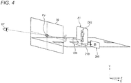
- Fig. 4 shows an example positional relationship between the eye point EP of the driver 19, the line of sight, and images.
- a visual attention center point Pp in a two-dimensional plane 30 can be calculated on the basis of a position of the eye point EP of the driver 19 detected by the line-of-sight detection device 14 and a direction of the line of sight.
- Relative positional relationships in the X-axis direction and the Y-axis direction between the visual attention center point Pp and virtual images of the respective display contents to be displayed in the content display region 20B etc. located on the far side in the Z direction (i.e., the side of an extension of the line of sight), the detected obstacle D02, and the display prohibition region A1 can also be calculated.
- Fig. 5 shows an example relationship between a real image of a detected obstacle D02, the visual attention point of the driver 19, and individual regions.
- the example shown in Fig. 5 is of a case that a pedestrian has appeared as a detected obstacle D02 in the front field of view of the driver 19 and the visual attention center point Pp is not located in an obstacle region A2.
- the obstacle region A2 is determined by the superimposition drawing control unit 12 as a rectangular region surrounding an obstacle center position Pc of the detected obstacle D02 detected by the obstacle detection device 16, using the obstacle center position Pc as a reference.
- the obstacle region A2 is determined by, for example, a top-left coordinates PLT and a bottom-right coordinates PRB in the two-dimensional plane 30 (X-Y coordinate plane).
- a display prohibition region A1 of the detected obstacle D02 is determined on the basis of the obstacle region A2 and the visual attention center point Pp. More specifically, the display prohibition region A1 is determined as an approximately rectangular region having round corners that contains and is larger than the obstacle region A2 by a region corresponding to a distance Lmin.
- the distance Lmin is determined as a minimum distance between the visual attention center point Pp and the outer circumference of the obstacle region A2. However, if the distance Lmin has a width that is longer than a corresponding width of the display range of the HUD main body 11, the display prohibition region A1 is determined so that the distance Lmin is fixed so as to have a width that is equal to half of the corresponding width of the display range.
- Fig. 6 shows another example relationship between a real image of a detected obstacle D02, the visual attention point of the driver 19, and individual regions.
- the example shown in Fig. 6 is of a case that a pedestrian has appeared as a detected obstacle D02 in the front field of view of the driver 19 and the visual attention center point Pp is located in an obstacle region A2.
- the obstacle region A2 is determined by the superimposition drawing control unit 12 as a rectangular region surrounding an obstacle center position Pc of the detected obstacle D02 detected by the obstacle detection device 16, using the obstacle center position Pc as a reference.
- the obstacle region A2 is determined by, for example, a top-left coordinates PLT and a bottom-right coordinates PRB in the two-dimensional plane 30 (X-Y coordinate plane).
- a display prohibition region A1B of the detected obstacle D02 is determined as a circular region that is centered at the visual attention center point Pp and has a radius that is equal to a distance Lmax.
- the distance Lmax is determined as a maximum distance between the visual attention center point Pp and the outer circumference of the obstacle region A2.
- the display prohibition region A1B is determined so that the distance Lmax is fixed so as to have a width that is equal to half of the corresponding width of the display range.
- Figs. 7A and 7B show further example relationships between a real image of a detected obstacle D02, the visual attention point of the driver 19, and individual regions.
- Figs. 7A and 7B are of a case that a the two-dimensional plane 30 located in the front field of view of the driver 19 is divided with the visual attention center point Pp as a reference into four regions, that is, a first region A01, a second region A02, a third region A03, and a fourth region A04, which are a bottom-right region, a top-right region, a bottom-left region, and a top-left region with respect to the X-Y coordinates of the visual attention center point Pp, respectively.
- the first region A01 and the third region A03 correspond to regions that are closer in actual distance in the depth direction (Z-axis direction) than the visual attention center point Pp and the second region A02 and the fourth region A04 correspond to regions that are farther in actual distance in the depth direction than the visual attention center point Pp.
- a detected obstacle D01 is located in the fourth region A04 and the detected obstacle D02 is located in the second region A02.
- a content display region 20B is set at such a position as to overlap with a display prohibition region A1 that is assigned to the detected obstacle D02 that has newly appeared.
- the superimposition drawing control unit 12 moves (relocates) the content display region 20B in the direction indicated by a movement vector 21B (radial direction) away from the visual attention center point Pp.
- the straight line connecting the visual attention center point Pp and the obstacle center position Pc is rotated about the visual attention center point Pp by various angles to search for an angle that prevents the content display region 20B from overlapping with the display prohibition region A1.
- the content display region 20B is relocated on the basis of a straight line extending in a direction of the movement vector 21B thus found so as to be located outside the display prohibition region A1.
- virtual images can be arranged so as to be suitable for real images as in the case of augmented reality.
- virtual images 17 of respective display contents can be displayed taking their positions in the depth direction into consideration. For example, when a new detected obstacle D02 has appeared, the content display regions 20B-20D are relocated, in the depth direction (Z-axis direction), to positions that are more distant from their current positions and do not cause the content display regions 20B-20D to overlap with the obstacle region A1 in the two-dimensional plane 30.
- Fig. 8 shows a first example main operation of the vehicular projection display apparatus.
- the superimposition drawing control unit 12 causes the HUD main body 11 to project images of respective display contents that are generated when necessary and causes virtual images 17 to be superimposed on a real image(s) using the augmented reality technique.
- the superimposition drawing control unit 12 performs the control shown in Fig. 8 in superimposing the virtual images 17.
- the control shown in Fig. 8 will be described below.
- step S11 when an obstacle has come close to the display range of the HUD main body 11 in the front field of view of the driver 19, the obstacle detection device 16 or the advanced driver assistance system 15 detects the presence of the obstacle and its position and shape.
- the superimposition drawing control unit 12 acquires information including the position of the detected obstacle from the advanced driver assistance system 15.
- the superimposition drawing control unit 12 acquires information indicating a latest line of sight of the driver 19 from the line-of-sight detection device 14.
- the superimposition drawing control unit 12 assigns priority ranks to plural respective display contents to be displayed by the superimposition drawing control unit 12. For example, step S13 may be executed in a process that is executed repeatedly on a regular basis.
- Each assigned priority rank is determined so as to reflect the degree of importance of a corresponding content. For example, the degree of importance of each content is calculated on the basis of the degree of danger and required freshness of information and a priority rank is assigned on the basis of the determined degree of importance.
- the superimposition drawing control unit 12 can determine coordinates of a visual attention point (visual attention center point Pp) that is a far point on the line of sight on the basis of the information indicating (the direction of) the line of sight. If a new obstacle is detected that is approaching the display range of the HUD main body 11, at step S14 the superimposition drawing control unit 12 monitors the position information of the obstacle detected at step S11 and the coordinates of the visual attention point while comparing them and judges whether the visual attention center point Pp has stayed in an obstacle region A2 of the new obstacle for a prescribed time.
- a visual attention point visual attention center point
- step S15 if the visual attention center point Pp has stayed in the obstacle region A2 for the prescribed time, that is, the driver 19 is already aware of the new obstacle. In this case, although it is not necessary to arouse attention of the driver 19 cause him or her to recognize the presence of the new obstacle, it is necessary to prevent virtual images 17 from obstructing visual recognition of this obstacle. Thus, at step S15, the superimposition drawing control unit 12 turns on location adjustment flags of all display contents.
- step S16 the superimposition drawing control unit 12 employs only display contents whose priority ranks are lower than the priority rank of a display content (CA) for arousing attention to the new obstacle and turns on location adjustment flags of these display contents.
- CA display content
- the superimposition drawing control unit 12 adjusts the display positions of the respective display contents in order that were made relocation targets at step S15 or S16, that is, the display contents whose location adjustment flags are on. More specifically, first, at step S17, the superimposition drawing control unit 12 selects a display content (CD) having the lowest priority rank as a position adjustment target of this time. After completion of position adjustment of this display content, at step S23 the superimposition drawing control unit 12 selects, as a position adjustment target of this time, a display content whose priority rank is lowest next to the display content just processed. If its location adjustment flag is on, it is subjected to position adjustment. The display positions of the respective relocation target display contents are adjusted in order by executing steps S18-S23 repeatedly.
- the display positions of the respective relocation target display contents are adjusted in the following manner.
- the obstacle detection device 16 measures a distance to the new obstacle and the superimposition drawing control unit 12 acquires information of a distance in the depth direction (Z-axis direction) from the eye point EP of the driver 19 to the obstacle that is located at a far position on the line of sight.
- the superimposition drawing control unit 12 sets the display position of the adjustment target display content outside the display prohibition regions A0 and A1 (within the projection surface) in the two-dimensional plane 30 and moves the adjustment target display content to a position that is farther than the obstacle using the distance information acquired at step S19. For example, where the display content is displayed on the road surface, the superimposition drawing control unit 12 changes the display position of the display content so that it is positioned at a farther position on the road surface.
- the superimposition drawing control unit 12 turns off the location adjustment flag of the display-position-adjusted display content.
- an icon is displayed for a prescribed time as a replacement of the display content concerned.
- the process shown in Fig. 8 is executed repeatedly by the superimposition drawing control unit 12.
- the process shown in Fig. 8 is executed and display contents are relocated when necessary at least every time the obstacle detection device 16 detects a new obstacle.
- the driver 19 has adjusted the position or posture of the seat or changed the position of his or her face or head, the position of the eye point EP to be detected by the line-of-sight detection device 14 and the direction of the line of sight vary and the display positions of the respective display contents are automatically adjusted accordingly. That is, virtual images 17 of the respective display contents are displayed at proper positions so that the relative positional relationships between the virtual images 17 and real images do not vary in the front field of view of the driver 19.
- Fig. 9 shows a second example main operation of the vehicular projection display apparatus.
- the example operation shown in Fig. 9 is a modified version of the first example operation shown in Fig. 8 .
- the superimposition drawing control unit 12 causes the HUD main body 11 to project generated display contents and causes a virtual image 17 to be superimposed on real images using the augmented reality technique.
- a control shown in Fig. 9 that is performed by the superimposition drawing control unit 12 in doing such superimposition display will be described below.
- the superimposition drawing control unit 12 calculates the degrees of importance of plural respective display contents (CA-CD) and updates their current degrees of importance on a regular basis.
- CA-CD respective display contents
- One example is to properly calculate the degrees of importance of respective display contents so that they reflect a variation of the vehicle speed, variations of the distances to respective detected obstacles, a variation of the number of detected obstacles, a variation of the characteristics of the road on which the vehicle is running, a variation of the ambient brightness, a variation of the time slot, or the like.
- the superimposition drawing control unit 12 compares variation amounts of the respective display contents with a predetermined threshold value. If there exists a display content whose variation in the degree of importance is larger than or equal to the threshold value, the process moves to step S33 to perform relocation of the display contents. That is, in the process shown in Fig. 9 , the display contents are relocated according to respective variations of their degrees of importance irrespective of detection of a new obstacle or occurrence of an event that changes the line of sight of the driver 19. By restricting the timing of execution of relocation to only timing when there exists a display content whose degree of importance has changed to a large extent, it becomes possible to avoid frequent relocation and lowering in visibility and prevent the driver 19 from feeling annoying.
- the superimposition drawing control unit 12 assigns priority ranks to the respective display contents according to their latest degrees of importance (i.e., results of the update at step S31). More specifically, the superimposition drawing control unit 12 elevates the priority rank of a display content whose degree of importance is high and lowers the priority rank of a display content whose degree of importance is low.
- the superimposition drawing control unit 12 judges whether the processing target display content requires superimposition on a real image. For example, a display content for arousing attention to an obstacle and a display content such as a road sign or a mark on a road surface need to be displayed so as to be suitable for an obstacle or a position on the road (real image). On the other hand, it is not necessary to adjust the position of a display content indicating a vehicle state such as a running speed so as to be superimposed on any real image.
- step S35 the superimposition drawing control unit 12 changes the display position of the processing target display content in the two-dimensional plane 30 so that it is moved outward in the radial direction away from the visual attention center point Pp, according to its priority rank assigned at step S33.
- a display content having a high priority rank such as one for arousing attention to an obstacle is excluded from the targets of relocation.
- step S34 the process moves from step S34 to step S36.
- step S36 the superimposition drawing control unit 12 moves the processing target display content to a position that is closer to the driver 19 than before the movement. As a result, the visibility of the relocated display content is increased.
- the first region A01 and the third region A03 which are located below the visual attention center point Pp are close to the driver 19 in the depth direction and the second region A02 and the fourth region A04 which are located above the visual attention center point Pp are distant from the driver 19 in the depth direction.
- the movement destination of a display content that need not be superimposed on any real image is set in the first region A01 or the third region A03 irrespective of the positions of real images and such a display content is moved to a position that is located below or outside, in the radial direction, the position before the movement.
- the relocation at step S36 may cause the processing target display content to be superimposed on a display prohibition region A1 (step S37). In this case, the process moves from step S37 to step S38, where the superimposition drawing control unit 12 moves the display position of the display content outward again.
- a straight line connecting the visual attention center point Pp and the obstacle center position Pc is rotated about the visual attention center point Pp to search for an angle that prevents the display content display region from overlapping with the display prohibition region A1.
- the content display region (20B) is relocated on the basis of a direction thus found so as to be located outside the display prohibition region A1.
- the superimposition drawing control unit 12 In relocating the processing target display content, the superimposition drawing control unit 12 also performs three-dimensional location adjustment at step S39. More specifically, in moving the display position of the display content outward in the radial direction in the two-dimensional plane 30, the superimposition drawing control unit 12 moves the display content to a position that is farther than the current display position and outside the display prohibition regions A0 and A1 according to, for example, the positions of real images, that is, a scene outside the vehicle.
- the display contents are relocated so that their virtual images do not obstruct visual recognition of a real image of the obstacle (S15). This makes it easier to secure the safety of a drive.
- display contents whose priority ranks are lower than the priority rank of a display content CA for arousing attention to the new object are relocated to positions that are distant from the new object while the display content CA is kept displayed in the vicinity of the new obstacle (S16). This allows the driver 19 to recognize the presence of the new object easily.
Landscapes
- Engineering & Computer Science (AREA)
- Physics & Mathematics (AREA)
- Mechanical Engineering (AREA)
- Multimedia (AREA)
- General Physics & Mathematics (AREA)
- General Engineering & Computer Science (AREA)
- Theoretical Computer Science (AREA)
- Combustion & Propulsion (AREA)
- Chemical & Material Sciences (AREA)
- Transportation (AREA)
- Optics & Photonics (AREA)
- Human Computer Interaction (AREA)
- Instrument Panels (AREA)
- Fittings On The Vehicle Exterior For Carrying Loads, And Devices For Holding Or Mounting Articles (AREA)
- Traffic Control Systems (AREA)
- Controls And Circuits For Display Device (AREA)
Applications Claiming Priority (1)
| Application Number | Priority Date | Filing Date | Title |
|---|---|---|---|
| JP2018041024A JP7048358B2 (ja) | 2018-03-07 | 2018-03-07 | 車両用表示投影装置 |
Publications (2)
| Publication Number | Publication Date |
|---|---|
| EP3536533A1 true EP3536533A1 (fr) | 2019-09-11 |
| EP3536533B1 EP3536533B1 (fr) | 2020-06-10 |
Family
ID=65657344
Family Applications (1)
| Application Number | Title | Priority Date | Filing Date |
|---|---|---|---|
| EP19160219.2A Active EP3536533B1 (fr) | 2018-03-07 | 2019-03-01 | Appareil d'affichage par projection de véhicule |
Country Status (4)
| Country | Link |
|---|---|
| US (1) | US20190278080A1 (fr) |
| EP (1) | EP3536533B1 (fr) |
| JP (1) | JP7048358B2 (fr) |
| CN (1) | CN110244460B (fr) |
Families Citing this family (7)
| Publication number | Priority date | Publication date | Assignee | Title |
|---|---|---|---|---|
| CN109478339A (zh) * | 2016-07-29 | 2019-03-15 | 三菱电机株式会社 | 显示装置、显示控制装置和显示控制方法 |
| US10810773B2 (en) * | 2017-06-14 | 2020-10-20 | Dell Products, L.P. | Headset display control based upon a user's pupil state |
| JP7257623B2 (ja) * | 2019-09-20 | 2023-04-14 | パナソニックIpマネジメント株式会社 | 表示制御装置および表示制御方法 |
| JP7327369B2 (ja) * | 2020-12-04 | 2023-08-16 | トヨタ自動車株式会社 | 電動アシスト装置およびプログラム |
| CN114103637B (zh) * | 2021-11-15 | 2023-11-03 | 佛吉亚歌乐电子(丰城)有限公司 | 一种显示装置、显示方法、车辆及存储介质 |
| JP2023074546A (ja) * | 2021-11-18 | 2023-05-30 | 本田技研工業株式会社 | 情報表示装置 |
| CN114296239A (zh) * | 2021-12-31 | 2022-04-08 | 合众新能源汽车有限公司 | 一种车辆车窗的图像显示方法及装置 |
Citations (5)
| Publication number | Priority date | Publication date | Assignee | Title |
|---|---|---|---|---|
| US20140368540A1 (en) * | 2013-06-14 | 2014-12-18 | Denso Corporation | In-vehicle display apparatus and program product |
| JP2015134521A (ja) * | 2014-01-16 | 2015-07-27 | 三菱電機株式会社 | 車両情報表示制御装置 |
| WO2017094427A1 (fr) * | 2015-12-01 | 2017-06-08 | 日本精機株式会社 | Afficheur tête haute |
| WO2017134861A1 (fr) * | 2016-02-05 | 2017-08-10 | 日立マクセル株式会社 | Dispositif d'affichage tête haute |
| JP2017149335A (ja) | 2016-02-25 | 2017-08-31 | 京セラ株式会社 | 運転支援情報表示装置 |
Family Cites Families (4)
| Publication number | Priority date | Publication date | Assignee | Title |
|---|---|---|---|---|
| DE102010001684A1 (de) * | 2010-02-09 | 2011-08-11 | Robert Bosch GmbH, 70469 | Verfahren zum Betreiben eines Head-Up-Display-Systems, Head-Up-Display-System |
| JP2015075510A (ja) * | 2013-10-07 | 2015-04-20 | 日本精機株式会社 | 投影装置及び虚像表示装置 |
| JP6598255B2 (ja) | 2014-03-31 | 2019-10-30 | エイディシーテクノロジー株式会社 | 運転支援装置、及び運転支援システム |
| WO2018150956A1 (fr) * | 2017-02-17 | 2018-08-23 | 日本精機株式会社 | Appareil d'affichage de véhicule |
-
2018
- 2018-03-07 JP JP2018041024A patent/JP7048358B2/ja active Active
-
2019
- 2019-03-01 EP EP19160219.2A patent/EP3536533B1/fr active Active
- 2019-03-06 US US16/294,115 patent/US20190278080A1/en not_active Abandoned
- 2019-03-07 CN CN201910171673.6A patent/CN110244460B/zh active Active
Patent Citations (5)
| Publication number | Priority date | Publication date | Assignee | Title |
|---|---|---|---|---|
| US20140368540A1 (en) * | 2013-06-14 | 2014-12-18 | Denso Corporation | In-vehicle display apparatus and program product |
| JP2015134521A (ja) * | 2014-01-16 | 2015-07-27 | 三菱電機株式会社 | 車両情報表示制御装置 |
| WO2017094427A1 (fr) * | 2015-12-01 | 2017-06-08 | 日本精機株式会社 | Afficheur tête haute |
| WO2017134861A1 (fr) * | 2016-02-05 | 2017-08-10 | 日立マクセル株式会社 | Dispositif d'affichage tête haute |
| JP2017149335A (ja) | 2016-02-25 | 2017-08-31 | 京セラ株式会社 | 運転支援情報表示装置 |
Also Published As
| Publication number | Publication date |
|---|---|
| US20190278080A1 (en) | 2019-09-12 |
| JP2019155960A (ja) | 2019-09-19 |
| EP3536533B1 (fr) | 2020-06-10 |
| JP7048358B2 (ja) | 2022-04-05 |
| CN110244460B (zh) | 2022-04-01 |
| CN110244460A (zh) | 2019-09-17 |
Similar Documents
| Publication | Publication Date | Title |
|---|---|---|
| EP3536533B1 (fr) | Appareil d'affichage par projection de véhicule | |
| US7605773B2 (en) | Head-up display system and method for carrying out the location-correct display of an object situated outside a vehicle with regard to the position of the driver | |
| US11181737B2 (en) | Head-up display device for displaying display items having movement attribute or fixed attribute, display control method, and control program | |
| JP7052786B2 (ja) | 表示制御装置および表示制御プログラム | |
| US20170254659A1 (en) | Virtual image presentation system, image projection device, and virtual image presentation method | |
| JP6459205B2 (ja) | 車両用表示システム | |
| US20110279452A1 (en) | Map display apparatus | |
| JP6695049B2 (ja) | 表示装置及び表示制御方法 | |
| US11803053B2 (en) | Display control device and non-transitory tangible computer-readable medium therefor | |
| US11525694B2 (en) | Superimposed-image display device and computer program | |
| US20210110791A1 (en) | Method, device and computer-readable storage medium with instructions for controllling a display of an augmented-reality head-up display device for a transportation vehicle | |
| JP2017215816A (ja) | 情報表示装置、情報表示システム、情報表示方法及びプログラム | |
| WO2019230272A1 (fr) | Dispositif de commande d'affichage, programme de commande d'affichage et support d'enregistrement lisible par ordinateur tangible persistant associé | |
| US11325470B2 (en) | Method, device and computer-readable storage medium with instructions for controlling a display of an augmented-reality head-up display device for a transportation vehicle | |
| KR20200075328A (ko) | 차량의 주행 정보 제공 방법, 장치 및 기록매체 | |
| JP7255608B2 (ja) | 表示制御装置、方法、及びコンピュータ・プログラム | |
| JP7459883B2 (ja) | 表示制御装置、ヘッドアップディスプレイ装置、及び方法 | |
| JP4277678B2 (ja) | 車両運転支援装置 | |
| KR101209796B1 (ko) | 전경 투과 기능을 갖는 차량용 표시장치 및 이의 표시방법 | |
| JP2022084266A (ja) | 表示制御装置、表示装置、及び画像の表示制御方法 | |
| US20230022485A1 (en) | Vehicle display control device, vehicle display device, vehicle display control method, and non-transitory storage medium | |
| JP7481333B2 (ja) | 表示装置 | |
| JP5071033B2 (ja) | 経路案内装置及び経路案内方法 | |
| WO2020121810A1 (fr) | Dispositif de commande d'affichage, programme de commande d'affichage et support d'enregistrement tangible non transitoire lisible par ordinateur | |
| WO2020084827A1 (fr) | Dispositif d'affichage d'image superposée et programme informatique |
Legal Events
| Date | Code | Title | Description |
|---|---|---|---|
| PUAI | Public reference made under article 153(3) epc to a published international application that has entered the european phase |
Free format text: ORIGINAL CODE: 0009012 |
|
| STAA | Information on the status of an ep patent application or granted ep patent |
Free format text: STATUS: REQUEST FOR EXAMINATION WAS MADE |
|
| 17P | Request for examination filed |
Effective date: 20190301 |
|
| AK | Designated contracting states |
Kind code of ref document: A1 Designated state(s): AL AT BE BG CH CY CZ DE DK EE ES FI FR GB GR HR HU IE IS IT LI LT LU LV MC MK MT NL NO PL PT RO RS SE SI SK SM TR |
|
| AX | Request for extension of the european patent |
Extension state: BA ME |
|
| GRAP | Despatch of communication of intention to grant a patent |
Free format text: ORIGINAL CODE: EPIDOSNIGR1 |
|
| STAA | Information on the status of an ep patent application or granted ep patent |
Free format text: STATUS: GRANT OF PATENT IS INTENDED |
|
| INTG | Intention to grant announced |
Effective date: 20200402 |
|
| RIC1 | Information provided on ipc code assigned before grant |
Ipc: B60K 35/00 20060101AFI20200320BHEP Ipc: G02B 27/01 20060101ALI20200320BHEP |
|
| GRAS | Grant fee paid |
Free format text: ORIGINAL CODE: EPIDOSNIGR3 |
|
| GRAA | (expected) grant |
Free format text: ORIGINAL CODE: 0009210 |
|
| STAA | Information on the status of an ep patent application or granted ep patent |
Free format text: STATUS: THE PATENT HAS BEEN GRANTED |
|
| AK | Designated contracting states |
Kind code of ref document: B1 Designated state(s): AL AT BE BG CH CY CZ DE DK EE ES FI FR GB GR HR HU IE IS IT LI LT LU LV MC MK MT NL NO PL PT RO RS SE SI SK SM TR |
|
| REG | Reference to a national code |
Ref country code: GB Ref legal event code: FG4D |
|
| REG | Reference to a national code |
Ref country code: CH Ref legal event code: EP Ref country code: AT Ref legal event code: REF Ref document number: 1278911 Country of ref document: AT Kind code of ref document: T Effective date: 20200615 |
|
| REG | Reference to a national code |
Ref country code: DE Ref legal event code: R096 Ref document number: 602019000167 Country of ref document: DE |
|
| REG | Reference to a national code |
Ref country code: IE Ref legal event code: FG4D |
|
| REG | Reference to a national code |
Ref country code: LT Ref legal event code: MG4D |
|
| PG25 | Lapsed in a contracting state [announced via postgrant information from national office to epo] |
Ref country code: LT Free format text: LAPSE BECAUSE OF FAILURE TO SUBMIT A TRANSLATION OF THE DESCRIPTION OR TO PAY THE FEE WITHIN THE PRESCRIBED TIME-LIMIT Effective date: 20200610 Ref country code: FI Free format text: LAPSE BECAUSE OF FAILURE TO SUBMIT A TRANSLATION OF THE DESCRIPTION OR TO PAY THE FEE WITHIN THE PRESCRIBED TIME-LIMIT Effective date: 20200610 Ref country code: GR Free format text: LAPSE BECAUSE OF FAILURE TO SUBMIT A TRANSLATION OF THE DESCRIPTION OR TO PAY THE FEE WITHIN THE PRESCRIBED TIME-LIMIT Effective date: 20200911 Ref country code: NO Free format text: LAPSE BECAUSE OF FAILURE TO SUBMIT A TRANSLATION OF THE DESCRIPTION OR TO PAY THE FEE WITHIN THE PRESCRIBED TIME-LIMIT Effective date: 20200910 Ref country code: SE Free format text: LAPSE BECAUSE OF FAILURE TO SUBMIT A TRANSLATION OF THE DESCRIPTION OR TO PAY THE FEE WITHIN THE PRESCRIBED TIME-LIMIT Effective date: 20200610 |
|
| REG | Reference to a national code |
Ref country code: NL Ref legal event code: MP Effective date: 20200610 |
|
| PG25 | Lapsed in a contracting state [announced via postgrant information from national office to epo] |
Ref country code: RS Free format text: LAPSE BECAUSE OF FAILURE TO SUBMIT A TRANSLATION OF THE DESCRIPTION OR TO PAY THE FEE WITHIN THE PRESCRIBED TIME-LIMIT Effective date: 20200610 Ref country code: HR Free format text: LAPSE BECAUSE OF FAILURE TO SUBMIT A TRANSLATION OF THE DESCRIPTION OR TO PAY THE FEE WITHIN THE PRESCRIBED TIME-LIMIT Effective date: 20200610 Ref country code: LV Free format text: LAPSE BECAUSE OF FAILURE TO SUBMIT A TRANSLATION OF THE DESCRIPTION OR TO PAY THE FEE WITHIN THE PRESCRIBED TIME-LIMIT Effective date: 20200610 Ref country code: BG Free format text: LAPSE BECAUSE OF FAILURE TO SUBMIT A TRANSLATION OF THE DESCRIPTION OR TO PAY THE FEE WITHIN THE PRESCRIBED TIME-LIMIT Effective date: 20200910 |
|
| REG | Reference to a national code |
Ref country code: AT Ref legal event code: MK05 Ref document number: 1278911 Country of ref document: AT Kind code of ref document: T Effective date: 20200610 |
|
| PG25 | Lapsed in a contracting state [announced via postgrant information from national office to epo] |
Ref country code: AL Free format text: LAPSE BECAUSE OF FAILURE TO SUBMIT A TRANSLATION OF THE DESCRIPTION OR TO PAY THE FEE WITHIN THE PRESCRIBED TIME-LIMIT Effective date: 20200610 Ref country code: NL Free format text: LAPSE BECAUSE OF FAILURE TO SUBMIT A TRANSLATION OF THE DESCRIPTION OR TO PAY THE FEE WITHIN THE PRESCRIBED TIME-LIMIT Effective date: 20200610 |
|
| PG25 | Lapsed in a contracting state [announced via postgrant information from national office to epo] |
Ref country code: PT Free format text: LAPSE BECAUSE OF FAILURE TO SUBMIT A TRANSLATION OF THE DESCRIPTION OR TO PAY THE FEE WITHIN THE PRESCRIBED TIME-LIMIT Effective date: 20201012 Ref country code: IT Free format text: LAPSE BECAUSE OF FAILURE TO SUBMIT A TRANSLATION OF THE DESCRIPTION OR TO PAY THE FEE WITHIN THE PRESCRIBED TIME-LIMIT Effective date: 20200610 Ref country code: EE Free format text: LAPSE BECAUSE OF FAILURE TO SUBMIT A TRANSLATION OF THE DESCRIPTION OR TO PAY THE FEE WITHIN THE PRESCRIBED TIME-LIMIT Effective date: 20200610 Ref country code: AT Free format text: LAPSE BECAUSE OF FAILURE TO SUBMIT A TRANSLATION OF THE DESCRIPTION OR TO PAY THE FEE WITHIN THE PRESCRIBED TIME-LIMIT Effective date: 20200610 Ref country code: SM Free format text: LAPSE BECAUSE OF FAILURE TO SUBMIT A TRANSLATION OF THE DESCRIPTION OR TO PAY THE FEE WITHIN THE PRESCRIBED TIME-LIMIT Effective date: 20200610 Ref country code: ES Free format text: LAPSE BECAUSE OF FAILURE TO SUBMIT A TRANSLATION OF THE DESCRIPTION OR TO PAY THE FEE WITHIN THE PRESCRIBED TIME-LIMIT Effective date: 20200610 Ref country code: RO Free format text: LAPSE BECAUSE OF FAILURE TO SUBMIT A TRANSLATION OF THE DESCRIPTION OR TO PAY THE FEE WITHIN THE PRESCRIBED TIME-LIMIT Effective date: 20200610 Ref country code: CZ Free format text: LAPSE BECAUSE OF FAILURE TO SUBMIT A TRANSLATION OF THE DESCRIPTION OR TO PAY THE FEE WITHIN THE PRESCRIBED TIME-LIMIT Effective date: 20200610 |
|
| PG25 | Lapsed in a contracting state [announced via postgrant information from national office to epo] |
Ref country code: SK Free format text: LAPSE BECAUSE OF FAILURE TO SUBMIT A TRANSLATION OF THE DESCRIPTION OR TO PAY THE FEE WITHIN THE PRESCRIBED TIME-LIMIT Effective date: 20200610 Ref country code: PL Free format text: LAPSE BECAUSE OF FAILURE TO SUBMIT A TRANSLATION OF THE DESCRIPTION OR TO PAY THE FEE WITHIN THE PRESCRIBED TIME-LIMIT Effective date: 20200610 Ref country code: IS Free format text: LAPSE BECAUSE OF FAILURE TO SUBMIT A TRANSLATION OF THE DESCRIPTION OR TO PAY THE FEE WITHIN THE PRESCRIBED TIME-LIMIT Effective date: 20201010 |
|
| REG | Reference to a national code |
Ref country code: DE Ref legal event code: R097 Ref document number: 602019000167 Country of ref document: DE |
|
| PLBE | No opposition filed within time limit |
Free format text: ORIGINAL CODE: 0009261 |
|
| STAA | Information on the status of an ep patent application or granted ep patent |
Free format text: STATUS: NO OPPOSITION FILED WITHIN TIME LIMIT |
|
| PG25 | Lapsed in a contracting state [announced via postgrant information from national office to epo] |
Ref country code: DK Free format text: LAPSE BECAUSE OF FAILURE TO SUBMIT A TRANSLATION OF THE DESCRIPTION OR TO PAY THE FEE WITHIN THE PRESCRIBED TIME-LIMIT Effective date: 20200610 |
|
| 26N | No opposition filed |
Effective date: 20210311 |
|
| PG25 | Lapsed in a contracting state [announced via postgrant information from national office to epo] |
Ref country code: MC Free format text: LAPSE BECAUSE OF FAILURE TO SUBMIT A TRANSLATION OF THE DESCRIPTION OR TO PAY THE FEE WITHIN THE PRESCRIBED TIME-LIMIT Effective date: 20200610 |
|
| REG | Reference to a national code |
Ref country code: BE Ref legal event code: MM Effective date: 20210331 |
|
| PG25 | Lapsed in a contracting state [announced via postgrant information from national office to epo] |
Ref country code: IE Free format text: LAPSE BECAUSE OF NON-PAYMENT OF DUE FEES Effective date: 20210301 Ref country code: LU Free format text: LAPSE BECAUSE OF NON-PAYMENT OF DUE FEES Effective date: 20210301 Ref country code: FR Free format text: LAPSE BECAUSE OF NON-PAYMENT OF DUE FEES Effective date: 20210331 |
|
| PG25 | Lapsed in a contracting state [announced via postgrant information from national office to epo] |
Ref country code: BE Free format text: LAPSE BECAUSE OF NON-PAYMENT OF DUE FEES Effective date: 20210331 |
|
| REG | Reference to a national code |
Ref country code: CH Ref legal event code: PL |
|
| PG25 | Lapsed in a contracting state [announced via postgrant information from national office to epo] |
Ref country code: LI Free format text: LAPSE BECAUSE OF NON-PAYMENT OF DUE FEES Effective date: 20220331 Ref country code: CH Free format text: LAPSE BECAUSE OF NON-PAYMENT OF DUE FEES Effective date: 20220331 |
|
| PG25 | Lapsed in a contracting state [announced via postgrant information from national office to epo] |
Ref country code: CY Free format text: LAPSE BECAUSE OF FAILURE TO SUBMIT A TRANSLATION OF THE DESCRIPTION OR TO PAY THE FEE WITHIN THE PRESCRIBED TIME-LIMIT Effective date: 20200610 |
|
| PG25 | Lapsed in a contracting state [announced via postgrant information from national office to epo] |
Ref country code: HU Free format text: LAPSE BECAUSE OF FAILURE TO SUBMIT A TRANSLATION OF THE DESCRIPTION OR TO PAY THE FEE WITHIN THE PRESCRIBED TIME-LIMIT; INVALID AB INITIO Effective date: 20190301 |
|
| PG25 | Lapsed in a contracting state [announced via postgrant information from national office to epo] |
Ref country code: SI Free format text: LAPSE BECAUSE OF FAILURE TO SUBMIT A TRANSLATION OF THE DESCRIPTION OR TO PAY THE FEE WITHIN THE PRESCRIBED TIME-LIMIT Effective date: 20200610 |
|
| GBPC | Gb: european patent ceased through non-payment of renewal fee |
Effective date: 20230301 |
|
| PG25 | Lapsed in a contracting state [announced via postgrant information from national office to epo] |
Ref country code: GB Free format text: LAPSE BECAUSE OF NON-PAYMENT OF DUE FEES Effective date: 20230301 |
|
| PG25 | Lapsed in a contracting state [announced via postgrant information from national office to epo] |
Ref country code: GB Free format text: LAPSE BECAUSE OF NON-PAYMENT OF DUE FEES Effective date: 20230301 |
|
| PG25 | Lapsed in a contracting state [announced via postgrant information from national office to epo] |
Ref country code: MK Free format text: LAPSE BECAUSE OF FAILURE TO SUBMIT A TRANSLATION OF THE DESCRIPTION OR TO PAY THE FEE WITHIN THE PRESCRIBED TIME-LIMIT Effective date: 20200610 |
|
| PGFP | Annual fee paid to national office [announced via postgrant information from national office to epo] |
Ref country code: DE Payment date: 20240130 Year of fee payment: 6 |