WO2019230272A1 - Dispositif de commande d'affichage, programme de commande d'affichage et support d'enregistrement lisible par ordinateur tangible persistant associé - Google Patents
Dispositif de commande d'affichage, programme de commande d'affichage et support d'enregistrement lisible par ordinateur tangible persistant associé Download PDFInfo
- Publication number
- WO2019230272A1 WO2019230272A1 PCT/JP2019/017331 JP2019017331W WO2019230272A1 WO 2019230272 A1 WO2019230272 A1 WO 2019230272A1 JP 2019017331 W JP2019017331 W JP 2019017331W WO 2019230272 A1 WO2019230272 A1 WO 2019230272A1
- Authority
- WO
- WIPO (PCT)
- Prior art keywords
- display
- virtual image
- guidance
- superimposed
- vehicle
- Prior art date
Links
- 230000002085 persistent effect Effects 0.000 title claims description 5
- 238000013459 approach Methods 0.000 claims description 43
- 230000006870 function Effects 0.000 claims description 16
- 238000012545 processing Methods 0.000 claims description 9
- 238000000034 method Methods 0.000 description 21
- 230000008569 process Effects 0.000 description 18
- 230000008859 change Effects 0.000 description 11
- 238000012937 correction Methods 0.000 description 8
- 238000004891 communication Methods 0.000 description 7
- 230000007704 transition Effects 0.000 description 7
- 102100034112 Alkyldihydroxyacetonephosphate synthase, peroxisomal Human genes 0.000 description 5
- 101000799143 Homo sapiens Alkyldihydroxyacetonephosphate synthase, peroxisomal Proteins 0.000 description 5
- 238000000848 angular dependent Auger electron spectroscopy Methods 0.000 description 5
- 230000006399 behavior Effects 0.000 description 3
- 238000001514 detection method Methods 0.000 description 3
- 238000010586 diagram Methods 0.000 description 3
- 239000004973 liquid crystal related substance Substances 0.000 description 3
- 230000033001 locomotion Effects 0.000 description 3
- 230000003287 optical effect Effects 0.000 description 3
- 230000001133 acceleration Effects 0.000 description 2
- 230000009471 action Effects 0.000 description 2
- 238000004590 computer program Methods 0.000 description 2
- 238000012986 modification Methods 0.000 description 2
- 230000004048 modification Effects 0.000 description 2
- 230000004308 accommodation Effects 0.000 description 1
- 230000003044 adaptive effect Effects 0.000 description 1
- 230000003190 augmentative effect Effects 0.000 description 1
- 239000002131 composite material Substances 0.000 description 1
- 230000007423 decrease Effects 0.000 description 1
- 238000013461 design Methods 0.000 description 1
- 238000010191 image analysis Methods 0.000 description 1
- 238000003384 imaging method Methods 0.000 description 1
- 238000005259 measurement Methods 0.000 description 1
- 230000004044 response Effects 0.000 description 1
- 230000033764 rhythmic process Effects 0.000 description 1
- 229910052710 silicon Inorganic materials 0.000 description 1
- 239000010703 silicon Substances 0.000 description 1
- 230000002459 sustained effect Effects 0.000 description 1
- 230000000007 visual effect Effects 0.000 description 1
Images
Classifications
-
- G—PHYSICS
- G09—EDUCATION; CRYPTOGRAPHY; DISPLAY; ADVERTISING; SEALS
- G09G—ARRANGEMENTS OR CIRCUITS FOR CONTROL OF INDICATING DEVICES USING STATIC MEANS TO PRESENT VARIABLE INFORMATION
- G09G5/00—Control arrangements or circuits for visual indicators common to cathode-ray tube indicators and other visual indicators
- G09G5/36—Control arrangements or circuits for visual indicators common to cathode-ray tube indicators and other visual indicators characterised by the display of a graphic pattern, e.g. using an all-points-addressable [APA] memory
- G09G5/37—Details of the operation on graphic patterns
- G09G5/377—Details of the operation on graphic patterns for mixing or overlaying two or more graphic patterns
-
- B—PERFORMING OPERATIONS; TRANSPORTING
- B60—VEHICLES IN GENERAL
- B60K—ARRANGEMENT OR MOUNTING OF PROPULSION UNITS OR OF TRANSMISSIONS IN VEHICLES; ARRANGEMENT OR MOUNTING OF PLURAL DIVERSE PRIME-MOVERS IN VEHICLES; AUXILIARY DRIVES FOR VEHICLES; INSTRUMENTATION OR DASHBOARDS FOR VEHICLES; ARRANGEMENTS IN CONNECTION WITH COOLING, AIR INTAKE, GAS EXHAUST OR FUEL SUPPLY OF PROPULSION UNITS IN VEHICLES
- B60K35/00—Arrangement of adaptations of instruments
-
- B60K35/28—
-
- B—PERFORMING OPERATIONS; TRANSPORTING
- B60—VEHICLES IN GENERAL
- B60R—VEHICLES, VEHICLE FITTINGS, OR VEHICLE PARTS, NOT OTHERWISE PROVIDED FOR
- B60R16/00—Electric or fluid circuits specially adapted for vehicles and not otherwise provided for; Arrangement of elements of electric or fluid circuits specially adapted for vehicles and not otherwise provided for
- B60R16/02—Electric or fluid circuits specially adapted for vehicles and not otherwise provided for; Arrangement of elements of electric or fluid circuits specially adapted for vehicles and not otherwise provided for electric constitutive elements
-
- G—PHYSICS
- G01—MEASURING; TESTING
- G01C—MEASURING DISTANCES, LEVELS OR BEARINGS; SURVEYING; NAVIGATION; GYROSCOPIC INSTRUMENTS; PHOTOGRAMMETRY OR VIDEOGRAMMETRY
- G01C21/00—Navigation; Navigational instruments not provided for in groups G01C1/00 - G01C19/00
- G01C21/26—Navigation; Navigational instruments not provided for in groups G01C1/00 - G01C19/00 specially adapted for navigation in a road network
- G01C21/34—Route searching; Route guidance
- G01C21/36—Input/output arrangements for on-board computers
- G01C21/3626—Details of the output of route guidance instructions
-
- G—PHYSICS
- G06—COMPUTING; CALCULATING OR COUNTING
- G06F—ELECTRIC DIGITAL DATA PROCESSING
- G06F3/00—Input arrangements for transferring data to be processed into a form capable of being handled by the computer; Output arrangements for transferring data from processing unit to output unit, e.g. interface arrangements
- G06F3/14—Digital output to display device ; Cooperation and interconnection of the display device with other functional units
-
- B60K2360/166—
-
- B60K35/22—
-
- G—PHYSICS
- G09—EDUCATION; CRYPTOGRAPHY; DISPLAY; ADVERTISING; SEALS
- G09G—ARRANGEMENTS OR CIRCUITS FOR CONTROL OF INDICATING DEVICES USING STATIC MEANS TO PRESENT VARIABLE INFORMATION
- G09G2340/00—Aspects of display data processing
- G09G2340/04—Changes in size, position or resolution of an image
- G09G2340/0464—Positioning
-
- G—PHYSICS
- G09—EDUCATION; CRYPTOGRAPHY; DISPLAY; ADVERTISING; SEALS
- G09G—ARRANGEMENTS OR CIRCUITS FOR CONTROL OF INDICATING DEVICES USING STATIC MEANS TO PRESENT VARIABLE INFORMATION
- G09G2340/00—Aspects of display data processing
- G09G2340/12—Overlay of images, i.e. displayed pixel being the result of switching between the corresponding input pixels
-
- G—PHYSICS
- G09—EDUCATION; CRYPTOGRAPHY; DISPLAY; ADVERTISING; SEALS
- G09G—ARRANGEMENTS OR CIRCUITS FOR CONTROL OF INDICATING DEVICES USING STATIC MEANS TO PRESENT VARIABLE INFORMATION
- G09G2354/00—Aspects of interface with display user
-
- G—PHYSICS
- G09—EDUCATION; CRYPTOGRAPHY; DISPLAY; ADVERTISING; SEALS
- G09G—ARRANGEMENTS OR CIRCUITS FOR CONTROL OF INDICATING DEVICES USING STATIC MEANS TO PRESENT VARIABLE INFORMATION
- G09G2380/00—Specific applications
- G09G2380/10—Automotive applications
Definitions
- the present disclosure relates to a display control device that controls display of a virtual image, a display control program, and a persistent tangible computer-readable medium thereof.
- Patent Document 1 discloses a head-up display device that further displays a guidance image arranged above an instruction image in addition to an instruction image superimposed on a road surface to be instructed such as a branch point for making a right or left turn. It is disclosed. In Patent Document 1, while the instruction image is highlighted by approaching the branch point that is the instruction target, the visibility of the guide image is reduced.
- This disclosure is intended to provide a display control device, a display control program, and a sustained tangible computer-readable medium for realizing a virtual image display capable of supporting an occupant so that smooth driving can be performed.
- a display control device that is used in a vehicle and controls display of a virtual image that is visually recognized by an occupant of the vehicle generates a guidance display object image that guides the occupant of a travel route of the vehicle.
- a display generating unit that performs a distance grasping unit that grasps a remaining distance from the current location of the vehicle to a guidance point where route guidance is performed by the guidance display object, and a switching distance between the remaining distance from the current location of the vehicle to the guidance point
- the non-superimposed virtual image that is not superimposed on a specific superimposition target is displayed as the guidance display object image, and the guide display object image that replaces the non-superimposed virtual image when the remaining distance is shorter than the switching distance.
- a display control unit that displays a superimposed virtual image superimposed on a specific superimposition target.
- a display control program used in a vehicle and that controls display of a virtual image that is visually recognized by an occupant of the vehicle guides at least one processing unit to the occupant along a travel route of the vehicle.
- a display generating unit that generates a guidance display object image
- a distance grasping unit that grasps a remaining distance from the current location of the vehicle to a guidance point where route guidance is generated by the guidance display object image, and a distance from the current location of the vehicle to the guidance point
- a non-superimposed virtual image that is not superimposed on a specific superimposition target is displayed as the guidance display object image, and when the remaining distance becomes shorter than the switching distance, the non-superimposed virtual image is displayed.
- the guidance display object image to be replaced is caused to function as a display control unit that displays a superimposed virtual image superimposed on a specific superimposition target.
- a persistent tangible computer readable medium comprising computer-implemented instructions that are used in a vehicle to control the display of a virtual image that is visible to an occupant of the vehicle.
- the instruction generates a guidance display object image for guiding the occupant's travel route to the occupant, and calculates a remaining distance from the current location of the vehicle to a guidance point where route guidance is generated by the guidance display object.
- the guidance point is not clearly indicated by the guidance display object.
- the superimposed display is displayed as a guidance display object.
- the guidance display object can direct the occupant's attention to the superposition target at the timing when the superimposition target is easily recognized.
- the virtual image display can support the occupant so that smooth driving can be performed.
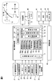
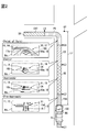
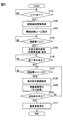
- the drawing It is a block diagram showing the overall image of the in-vehicle configuration related to the virtual image display system, It is a diagram showing an example of display transition from a non-superimposed image to a superimposed virtual image and a display transition of a plurality of superimposed virtual images in the process of route guidance, It is an idea of route guidance, it is a diagram showing a list of the correspondence between the remaining distance to the guidance point and the notification information, It is a figure which shows an example of the scene where a continuous branch occurs, It is a flowchart which shows the detail of the display control process implemented with a display control apparatus.
- the display control apparatus 100 includes the virtual image display system 10 used in the vehicle A together with a head-up display (hereinafter, “HUD”) device 30 and the like.
- the virtual image display system 10 displays a virtual image Vi that can be visually recognized by a passenger (for example, a driver) of the vehicle A.
- the virtual image display system 10 presents various information related to the vehicle A to the driver using the virtual image Vi.
- the display control device 100 can communicate with other in-vehicle configurations via a communication bus of the in-vehicle network.
- a navigation information providing unit 21, an ADAS information providing unit 22, a host vehicle information providing unit 27, a driver information providing unit 28, an in-vehicle device 40, and the like are directly or indirectly electrically connected to the communication bus.
- the navigation information providing unit 21 and the ADAS information providing unit 22 are configured to provide route guidance information related to route guidance to the display control device 100.
- the navigation information providing unit 21 includes at least a navigation device mounted on the vehicle A, and includes a map database, a GNSS (Global Navigation Satellite System) receiver, and an external communication device.
- the navigation information providing unit 21 includes route information to the destination set by the driver, the current position and direction of the host vehicle, congestion information indicating the degree of congestion of the road, type information indicating the road type, and coordinates of the intersection performing route guidance. And shape information and the like are output to the communication bus as route guidance information.
- the navigation information providing unit 21 may be configured to be able to communicate with a mobile terminal that can execute a navigation application.
- map data, route information, and the like acquired by communication with the mobile terminal are provided to the display control device 100 as route guidance information.
- the ADAS information providing unit 22 includes a locator 23, an external sensor 24, a driving support control system 25, and a high accuracy map database 26.
- the locator 23 indicates a lane on which the vehicle A travels by a composite positioning obtained by combining the positioning signal received by the GNSS receiver with the measurement information of the inertial sensor and the external sensor 24 and the high-accuracy map information. Generate precision position information.
- the external sensor 24 includes a front camera, a millimeter wave and quasi-millimeter wave radar, a lidar, a sonar, and the like.
- the external sensor 24 detects a stationary object and a moving object in real time from the periphery of the vehicle A, particularly from the front range of the vehicle A.
- the external sensor 24 detects road signs and traffic lights as stationary objects, pedestrians and cyclists as moving objects, and the like.
- the driving support control system 25 supports the driving operation of the driver by using the high-precision position information by the locator 23, the external world sensing information by the external sensor 24, the high-accuracy map information acquired from the high-accuracy map database 26, and the like.
- the driving support control system 25 has functional units that realize automatic driving functions such as ACC (Adaptive Cruise Control), LTC (lane trace control), LKA (Lane Keeping Assist), and the like.
- the driving support control system 25 has a functional unit that realizes a collision avoidance function such as FCW (Forward collision) and AEB (Automatic emergency braking).
- the high accuracy map database 26 stores high accuracy map information as map data with higher accuracy than the map data stored in the navigation information providing unit 21.
- the high-accuracy map includes information such as a three-dimensional position and shape of a pedestrian crossing, a stop line, a traffic sign, and a traffic light in addition to information such as a center line of a roadway and a connection between roads.
- the high-accuracy map database 26 interrupts the provision of high-accuracy map information in an area where the high-accuracy map is not yet developed.
- the ADAS information providing unit 22 provides the high-accuracy position information, the driving support control information of the driving support control system 25, the high-accuracy map information, and the like as route guidance information to the display control device 100.
- the own vehicle information providing unit 27 includes a plurality of in-vehicle sensors that measure the state of the vehicle A.
- the in-vehicle sensor includes a vehicle speed sensor, an acceleration sensor, a gyro sensor, and the like.
- the own vehicle information providing unit 27 provides information such as the current vehicle speed, acceleration, angular velocity, and vehicle attitude of the vehicle A to the display control device 100 as own vehicle movement information.
- the driver information providing unit 28 includes at least a driver status monitor (hereinafter referred to as “DSM”) mounted on the vehicle A, and includes a near infrared light source, a near infrared camera, and an image analysis unit. ing.
- the driver information providing unit 28 acquires information such as the driver's eye point EP, line-of-sight direction, and eye opening degree by analyzing a face image captured using a near-infrared camera.
- the driver information providing unit 28 provides the acquired driver sensing information to the display control apparatus 100.
- the in-vehicle device 40 is an electronic control unit mounted on the vehicle A, and is electrically connected to in-vehicle displays such as a combination meter 41, a multi-information display (MID) 42, and a center information display (CID) 43.
- the in-vehicle device 40 integrally controls information presentation to the driver in response to a control request to each in-vehicle display.
- map data, route information to the destination, and the like are displayed by the navigation device.
- the display screen of the CID 43 is a touch panel 44 that can be touched by a driver or the like. Based on an operation input to the touch panel 44, a destination can be set and a set value can be changed.
- the HUD device 30 is electrically connected to the display control device 100, and acquires video data generated by the display control device 100.
- the HUD device 30 is configured by a projector, a screen, a magnifying optical system, and the like.
- the HUD device 30 is accommodated in an accommodation space in the instrument panel below the windshield WS.
- the HUD device 30 projects the light of the display image formed as the virtual image Vi toward the projection range PA of the windshield WS.
- the light projected toward the windshield WS is reflected toward the driver's seat in the projection range PA and is perceived by the driver.
- the driver can visually recognize the display in which the virtual image Vi is superimposed on the superimposition target in the foreground that can be seen through the projection range PA.
- the projection range PA is a range in which light can be projected by the HUD device 30, and is a range in which the virtual image Vi can be displayed on the appearance of the driver.
- the projection range PA is a limited part of the entire surface of the windshield WS.
- the angle of view of the projection range PA is, for example, 12 ° in the horizontal (horizontal) direction and 4 ° in the vertical (vertical) direction.
- the HUD device 30 can superimpose and display the virtual image Vi only on an object within a range that can be seen through the projection range PA.
- the virtual image Vi is formed at a position relatively distant from the windshield WS, specifically, in a space of about 10 to 20 m from the eye point EP in the forward direction of the vehicle A.
- the virtual image Vi includes a superimposed virtual image 14 and a non-superimposed virtual image 12 (see FIG. 2).
- the superimposed virtual image 14 is superimposed and displayed on a specific superimposed object that can be seen through the projection range PA, for example, a preceding vehicle, a pedestrian, and a road surface.
- the superimposed virtual image 14 is movable along the superimposed object so as to be relatively fixed to the superimposed object, and presents information to the driver as a so-called augmented reality (AR) display object.
- AR augmented reality
- the non-superimposed virtual image 12 is a non-AR display object that is not superimposed on a specific superimposition target and is simply superimposed on the foreground.
- the non-superimposed virtual image 12 is displayed so as to be fixed to the windshield WS, for example.
- the display control device 100 is an electronic control unit that controls display of the virtual image Vi by the HUD device 30.
- the control circuit of the display control apparatus 100 is mainly configured by a computer having a processing unit 61, a RAM 62, a memory device 63, and an input / output interface.
- the processing unit 61 includes at least one of a CPU (Central Processing Unit) and a GPU (Graphics Processing Unit).
- the memory device 63 stores various programs executed by the processing unit 61.
- a plurality of application programs (50a to 50e) that generate content displayed as a virtual image, an information presentation management program that integrally controls the virtual image display of the content, and the like are stored as a display control program.
- the display control apparatus 100 includes a common information generation block 71 and an integrated display control block 73 as functional blocks based on the information presentation management program.
- the common information generation block 71 is information used in common by each of the superimposed display applications 50a to 50e and the integrated display control block 73, and acquires information necessary for design determination of the virtual image Vi from the communication bus.
- the common information generation block 71 can acquire driving support control information, own vehicle motion information, driver sensing information, and the like from the communication bus in addition to the route guidance information.
- the superimposed display applications 50a to 50e Based on the information provided by the common information generation block 71, the superimposed display applications 50a to 50e generate content related to the ADAS function and the cockpit function, and set the display flag thereof. Each of the superimposed display applications 50a to 50e is associated with the ACC function, the LKA function, the FCW function, and the navigation device of the driving support control system 25. Each of the superimposed display applications 50a to 50e individually determines content to be displayed as a virtual image according to the provided information, and issues a display request to the integrated display control block 73.
- the integrated display control block 73 generates video data of the virtual image Vi using information provided from the common information generation block 71 based on display requests from the respective superimposed display applications 50a to 50e.
- the integrated display control block 73 includes a display mediation unit 74, a superimposed display correction unit 75, and a drawing output unit 76.
- the display mediation unit 74 is a functional unit that adjusts the content to be displayed as the virtual image Vi.
- the display mediation unit 74 selects content with high priority from the acquired display requests and sets it as a virtual image display target. With such a setting, for example, content notifying high priority (urgent) information that is related to the FCW function, for example, is always displayed and displayed promptly.
- the superimposition display correction unit 75 generates correction information for correctly superimposing the superimposed virtual image 14 on the superimposition target based on the information acquired by the common information generation block 71.
- the correction information is information for adjusting the imaging position of the virtual image Vi on a virtual line that three-dimensionally connects the superimposition target and the eye point EP.
- the superimposed display correction unit 75 sequentially generates correction information in consideration of the relative position of the overlapping target, the position of the eye point EP, the vehicle posture, and the like.
- the drawing output unit 76 generates video data through a process of drawing the original image of the content selected by the display mediation unit 74.
- the drawing output unit 76 adjusts the drawing position and drawing shape of the original image based on the correction information from the superimposed display correction unit 75 in each frame of the video data.
- the drawing output unit 76 outputs the generated video data to the HUD device 30 in a predetermined video format.
- one of the superimposed display applications 50a to 50e is the TBT display application 50e.
- the TBT display application 50e controls the display of the guidance display object 11 that guides the driving route DR of the vehicle A to the driver based on the route information.
- the display of the guidance display object 11 is started with the approach to the guidance point GP such as an intersection and a branch, and is terminated when the guidance intersection passes.
- the integrated display control block 73 Based on the display request from the TBT display application 50e, the integrated display control block 73 generates video data including the guidance display object 11.
- the TBT display application 50e includes a distance grasping unit 51, a region limiting unit 52, and a display control unit 53 as sub functional blocks that control the display of the guidance display object 11.
- the distance grasping part 51 is based on the route guidance information, the current position and direction of the vehicle A, the guidance intersection coordinates, the shape of the guidance intersection serving as the guidance point GP, the exit direction at the guidance intersection based on the travel route DR, and guidance from the vehicle A.
- the remaining distance Lr to the intersection is grasped.
- the distance grasping unit 51 can grasp the current position and direction of the vehicle A using the high-accuracy position information.
- the area restriction unit 52 restricts the display permission range UA that allows the display of the superimposed virtual image 14 to a part of the projection range PA.
- the area restriction unit 52 defines the display permission range UA below the projection range PA so that the center of the display permission range UA is below the center of the projection range PA.
- the display permission range UA is defined to include the lower edge of the projection range PA.
- the area restriction unit 52 can enlarge / reduce the display permission range UA and expand the display permission range UA upward.
- the display permission range UA may be expanded to the entire projection range PA, for example.
- the region restriction unit 52 moves the upper edge of the display permission range UA upward as the remaining distance Lr to the guidance intersection is shorter, thereby defining the display permission range UA larger.
- the area restriction unit 52 changes the display permission range UA based on the recognition information about the front of the vehicle A.
- the recognition information includes detection information of a preceding vehicle based on external world sensing information, road shape information such as a gradient and a curve based on external world sensing information and high accuracy map information, and the like.
- the area restriction unit 52 expands the display permission range UA upward when a preceding vehicle that may overlap with the virtual image Vi is not detected.
- the region restriction unit 52 expands the display permission range UA upward and laterally in accordance with the gradient and the curve.
- the area restriction unit 52 can change the setting of the display permission range UA based on an operation input by an occupant such as a driver. Such an operation is input to an operation unit such as the touch panel 44 or the steering switch 45, for example.
- the driver can set the initial size of the display permission range UA before the enlargement, whether to permit the enlargement of the display permission range UA, and the like by inputting to the operation unit.
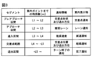
- the display control unit 53 switches the display object to display a virtual image according to the remaining distance Lr from the vehicle A to the guidance point GP, and suggests driving behavior corresponding to the remaining distance Lr to the driver.
- the display control unit 53 sets threshold distances such as a display start distance L1, a switching distance L2, an approach distance L3, an approach distance L4, and an exit distance L5 as threshold values to be compared with the remaining distance Lr.
- the display control unit 53 changes the notification information notified to the driver by dynamically switching the virtual image display based on the comparison between the remaining distance Lr and each threshold distance (L1 to L5), and at a necessary timing for the driver. Suggest necessary driving behavior.
- the display control unit 53 switches the guidance display object 11 from the non-superimposed virtual image 12 to the superimposed virtual image 14 according to the remaining distance Lr to the guidance point GP.
- the distance grasping unit 51 displays the non-superimposed virtual image 12 as the guidance display object 11 when the remaining distance Lr is longer than the switching distance L2.
- the display control unit 53 displays the superimposed virtual image 14 as the guidance display object 11 that replaces the non-superimposed virtual image 12.
- the superimposed virtual image 14 is displayed at substantially the same position as the non-superimposed virtual image 12 to indicate that it is a guidance display object 11 related to the non-superimposed virtual image 12. That is, at least a part of the display range of the superimposed virtual image 14 overlaps the display range of the non-superimposed virtual image 12.
- the display control unit 53 changes the aspect of the superimposed virtual image 14 based on the remaining distance Lr to the guide point GP.
- the superimposed virtual image 14 displayed as the guidance display object 11 includes a lane notification virtual image 15, a deceleration notification virtual image 16, a route notification virtual image 17, a completion notification virtual image, and the like.
- the display control unit 53 sequentially switches the superimposed virtual images 14 based on the comparison between the remaining distance Lr and each threshold distance (L2 to L5).
- the display control unit 53 changes the modes of the non-superimposed virtual image 12 and the superimposed virtual image 14 based on the driving environment information of the road serving as the driving route DR and the operation input by the driver or the like.
- Each threshold distance (L1 to L5) to be changed can be changed. According to the change of each threshold distance, the display start timing of the non-superimposed virtual image 12 and the superimposed virtual image 14 and the state transition timing for changing the aspect of the superimposed virtual image 14 are adjusted.
- the display control unit 53 uses, for example, road type information and congestion information included in the route guidance information as travel environment information. Based on the type information, the display control unit 53 sets each threshold distance longer when traveling on a road with a fast traffic flow such as a national road than when traveling on a road with a slow traffic flow. To do.
- the display control unit 53 sets each threshold distance (L1 to L5) based on time when it is estimated that the road is congested based on the congestion information. Specifically, the display control unit 53 sets each threshold distance (L1 to L5) based on the estimated arrival time to the guidance intersection before a specific second of arrival at the guidance intersection.
- the TBT display application 50e temporarily displays the intersection notification virtual image 13 that is the non-superimposed virtual image 12 as the guidance display object 11, and then the lane notification virtual image 15 that is the superimposed virtual image 14, the deceleration notification virtual image 16, and the route.
- the notification virtual image 17 and the completion notification virtual image are displayed in order.
- a plurality of route line portions 18 are drawn as common display elements.
- Each route line portion 18 has a shape extending linearly along the width direction of the road surface, and is lined up along the road surface serving as the travel route DR while being spaced apart from each other.
- the intersection notification virtual image 13 is a guidance display object 11 for notifying the approach to the guidance intersection as the guidance point GP.
- the intersection notification virtual image 13 is displayed in a manner in which a large number of route line portions 18 indicating exit directions from the guidance intersection are combined with the intersection shape image 13a indicating the overall shape of the guidance intersection.
- the intersection notification virtual image 13 is a non-AR display object, and is displayed as a virtual image with a size that extends over almost the entire projection range PA without being superimposed on a specific superimposition target.
- the intersection notification virtual image 13 is displayed as a virtual image in the pre-approach section PAS defined in front of the guide point GP.
- the pre-approach section PAS is a section where the remaining distance Lr to the guidance point GP is from the display start distance L1 to the switching distance L2.
- the display start distance L1 is set to a point where the remaining distance Lr is 700 m, for example.
- the switching distance L2 is set to a point where the remaining distance Lr is 300 m, for example.
- the display of the intersection notification virtual image 13 is started at the timing when the remaining distance Lr becomes the display start distance L1, and is ended when the specific time (several seconds) has elapsed from the start of display. The reason why the display of the intersection notification virtual image 13 is not continued until the switching distance L2 is to prevent the intersection notification virtual image 13 from covering the entire projection range PA for a long time.
- the TBT display application 50e indicates the moving direction of the vehicle A at the guidance intersection by performing an animation in which a plurality of route line portions 18 arranged along the travel route DR are displayed in order from the front (lower) side.
- the TBT display application 50e ends the display of the intersection notification virtual image 13 at a timing when a specific time has elapsed from the start of display.
- the specific time is defined in advance so that the animation of the route line unit 18 is displayed once or a plurality of times.
- the number of repetitions of such animation can be changed based on, for example, driver sensing information by DSM. As an example, when a driver's look-a-side that keeps an eye on the projection range PA is detected, the TBT display application 50e can increase the number of animation repetitions by extending the specific time.
- the lane notification virtual image 15 is a guidance display object 11 for notifying a recommended lane to which the driver should move the vehicle A before reaching the guidance intersection.
- the lane notification virtual image 15 is displayed in the display permission range UA.
- the lane notification virtual image 15 includes a road surface image 15a and a direction notification image 15b.
- the road surface image 15 a is superimposed on the front road surface of the vehicle A.
- the road surface image 15a is represented by a plurality of route line portions 18 extending linearly along the width direction of the road.
- the road surface image 15a is a display element drawn in a predetermined shape, and is displayed in a substantially constant shape regardless of the road form before the guidance intersection.
- the direction notification image 15b is displayed adjacent to the upper side or the lower side of each route line unit 18.
- the direction notification image 15 b has a shorter length than the route line portion 18 and extends linearly along the route line portion 18.
- the display color of the direction notification image 15b is different from the display color of the road surface image 15a.
- a part of each route line 18 that is desired for the direction notification image 15b is displayed in substantially the same display color as the direction notification image 15b.
- the relative left and right positions of the direction notification image 15b with respect to the road surface image 15a indicate the left and right directions in which the vehicle A is moved to the guidance intersection. That is, when it is necessary to move the vehicle A to the rightmost lane before the guidance intersection, the direction notification image 15b is displayed at the right end of the road surface image 15a. On the other hand, when it is necessary to move the vehicle A to the leftmost lane by the guidance intersection, the direction notification image 15b is displayed at the left end of the road surface image 15a.
- the lane notification virtual image 15 is displayed in the approach section AS.
- the approach section AS is defined on the side closer to the guide point GP than the pre-approach section PAS along the travel route DR.
- the approach section AS is a section where the remaining distance Lr to the guidance point GP is from the switching distance L2 to the approach distance L3.
- the approach distance L3 is set at a point where the remaining distance Lr is 100 m.
- the display of the lane notification virtual image 15 is started at the timing when the remaining distance Lr becomes the switching distance L2, and is continued until the remaining distance Lr becomes the approaching distance L3.
- the deceleration notification virtual image 16 is a guidance display object 11 that notifies a recommended speed when entering the guidance intersection and prompts the driver to decelerate. Similar to the lane notification virtual image 15, the deceleration notification virtual image 16 is displayed in the display permission range UA and includes a road surface image 16 a and a direction notification image 16 b. Unlike the road surface image 15a, the road surface image 16a has a plurality of route line portions 18 having a V shape. A road surface image 16 a made up of each downwardly convex (or upwardly convex) route line portion 18 is superimposed on the front road surface of the vehicle A.
- the direction notification image 16b is combined with the road surface image 16a and continuously indicates the left and right directions in which the vehicle A is moved to the guidance point GP.
- the deceleration notification virtual image 16 is changed to a mode for alerting the high traveling speed when it is determined that the approach speed to the guidance intersection is too high based on the traveling speed of the vehicle A.
- the TBT display application 50e sets a speed threshold corresponding to the remaining distance Lr. When the traveling speed of the vehicle A exceeds the speed threshold, the display color of the deceleration notification virtual image 16 is changed to, for example, red or amber.
- the deceleration notification virtual image 16 is displayed in the approach section ES.
- the approach section ES is defined on the side closer to the guide point GP than the approach section AS along the travel route DR.
- the approach section ES is a section where the remaining distance Lr to the guide point GP is from the approach distance L3 to the approach distance L4.
- the approach distance L4 is set to a point where the remaining distance Lr is 30 m.
- the display of the deceleration notification virtual image 16 is started at the timing when the remaining distance Lr becomes the approach distance L3 and is continued until the remaining distance Lr becomes the approach distance L4.
- the route notification virtual image 17 is a guidance display object 11 for notifying the driver of the position of a guidance intersection where a right or left turn or the like is made and the exit notification from the guidance intersection. Due to the upward expansion of the display permission range UA, the route notification virtual image 17 is displayed using almost the entire projection range PA.
- the route notification virtual image 17 includes a road surface image 16a continuously displayed from the deceleration notification virtual image 16 and a route image 17a.
- the route image 17a is arranged on both sides of the road surface image 16a and extends in a belt shape along the travel route DR.
- the route notification virtual image 17 is superimposed on the front road surface including the guidance point GP, and indicates the exit direction from the guidance intersection by the curvature of the route image 17a according to the travel route DR.
- the route notification virtual image 17 is displayed in the intersection range PT.
- the intersection range PT is defined to include the guide point GP.
- the intersection range PT is an area where the remaining distance Lr to the guidance point GP is from the approach distance L4 to the exit distance L5.
- the exit distance L5 is set to a point where the remaining distance Lr is minus 30 m, that is, a point 30 m from the guide point GP to the exit direction.
- the display of the route notification virtual image 17 is started at the timing when the remaining distance Lr becomes the approach distance L4 and continues until the remaining distance Lr becomes the exit distance L5.
- the completion notification virtual image is a guidance display object 11 for notifying the end of a left or right turn at a guidance intersection.
- the completion notification virtual image includes a road surface image superimposed on the front road surface.
- the completion notification virtual image indicates that the right / left turn has ended, and the normal travel along the road Encourage the driver to start.
- the completion notification virtual image is displayed in the exit section EXT.
- the exit section EXT is defined on the side farther from the guide point GP than the intersection range PT along the travel route DR.
- the display of the completion notification virtual image is displayed at the timing when the remaining distance Lr becomes the exit distance L5, and is ended when the animation is repeated a predetermined number of times.
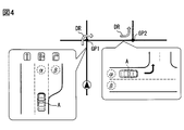
- the TBT display application 50e can change the display mode of the lane notification virtual image 15 and the deceleration notification virtual image 16.
- the TBT display application 50e can acquire a recommended lane on which the vehicle A should travel as route guidance information from the navigation device.
- the TBT display application 50e displays a lane having a display form different from that at the time of a normal right / left turn in the approach section AS and the approach section ES before the first guidance point (the branch point GP1).
- a notification virtual image 15 and a deceleration notification virtual image 16 are displayed.
- the TBT display application 50e has the lane notification virtual image 15 in which the direction notification image 15b is arranged in the center of the road surface image 15a and the direction notification image 16b in the center of the road surface image 16a, before the first branch point GP1. Are displayed in order.
- the TBT display application 50e guides to the center lane (see ⁇ in FIG. 4) instead of the rightmost lane (see ⁇ in FIG. 4). Do. If the driver has moved the vehicle A to the center lane according to the above display, a left turn at the second guidance point (branch point GP2) can be smoothly performed.
- the details of the display control processing executed by the display control device 100 in order to realize the display of the guidance display object 11 described so far will be described in detail based on FIG. 5 and with reference to FIGS. 1 and 2. To do.
- the display control process shown in FIG. 5 is started with the occurrence of a specific event as a trigger, for example, completion of route setting in a navigation device or the like.
- S101 the presence / absence of content to be displayed such as the guidance display object 11 is determined. If it is determined in S101 that there is content to be displayed, the process proceeds to S102. On the other hand, when it is determined that there is no content to be displayed, generation of content such as the guidance display object 11 is awaited by repeating S101.
- route guidance information and the like are acquired, and the process proceeds to S103.
- the route guidance information acquired in S102 includes recognition information, road driving environment information, and the like.
- the threshold distances (L1 to L5) are set based on the road environment information in the route guidance information acquired in S102, and the process proceeds to S104.
- the remaining distance Lr is grasped and it is determined whether the latest remaining distance Lr is less than the display start distance L1.
- the approach to the guide point GP is waited by repeating S104. Then, when the remaining distance Lr becomes less than the display start distance L1, the process proceeds to S105.
- the intersection notification virtual image 13 is displayed, and the process proceeds to S106.
- S106 it is determined whether or not the display end condition for the intersection notification virtual image 13 is satisfied. As described above, the elapsed time from the start of display, the number of times the animation is repeated, or the like is set as the display end condition of the intersection notification virtual image 13. If it is determined in S106 that the display end condition is satisfied, the process proceeds to S107.
- the remaining distance Lr and the threshold distances L2 to L5 are compared in order.
- the remaining distance Lr is grasped, and it is determined whether or not the latest remaining distance Lr is less than the switching distance L2.
- the approach to the guide point GP is waited by repeating S107. Then, at the timing when the remaining distance Lr becomes the switching distance L2, the process proceeds to S108.
- the display permission range UA corresponding to the presence or absence of the preceding vehicle and the road shape ahead is set, and the process proceeds to S109.
- the size of the display permission range UA set in S108 is increased as the number of repetitions increases.
- the display of the lane notification virtual image 15 is started, and the process proceeds to S110.
- the superimposed virtual image 14 is sequentially switched to the lane notification virtual image 15, the deceleration notification virtual image 16, the route notification virtual image 17, and the completion notification virtual image.
- the erasing condition is a preset condition, for example, a predetermined distance away from the guidance intersection, a predetermined time has elapsed from the start of displaying the completion notification virtual image, and the vehicle A has deviated from the travel route DR. If it is determined in S110 that the erasure condition is not satisfied, the process returns to S107. As a result, a comparison between the next threshold distance and the remaining distance Lr is performed. On the other hand, if it is determined in S110 that the erasure condition is satisfied, the process proceeds to S111. In S111, the display of the superimposed virtual image 14 is turned off, and the display control process ends.
- the non-superimposed virtual image 12 is displayed when the remaining distance Lr to the guidance point GP is longer than the switching distance L2. Therefore, the guidance point GP is not specified by the guidance display object 11. As a result, it is possible to prevent the occurrence of a task that forcibly recognizes the guide point GP that is located far away and is difficult to perceive.
- the superimposed virtual image 14 is displayed as the guidance display object 11 when the remaining distance Lr to the guidance point GP becomes shorter than the switching distance L2. According to such a change in the virtual image display, the guidance display object 11 can direct the driver's attention to the superimposition target at the timing when the superimposition target is easily recognized. As a result, the virtual image display can support the driver so that smooth driving can be performed.
- the region restriction unit 52 of the present embodiment restricts the display permission range UA that allows the display of the superimposed virtual image 14 to a part of the projection range PA. According to such limitation of the display range, an area where the superimposed virtual image 14 is easily displaced from the superimposition target in the angle of view of the HUD device 30 is not used for AR display. Therefore, the driver's uncomfortable feeling due to the superimposed deviation of the superimposed virtual image 14 is less likely to occur.
- the display permission range UA is defined in a lower range of the projection range PA. Therefore, the superimposed virtual image 14 such as the lane notification virtual image 15 and the deceleration notification virtual image 16 is drawn at a position where there is a high possibility of overlapping with the front road surface regardless of the vehicle A posture change, the road shape, and the like. According to the limitation of the display range as described above, it is difficult for superimposition deviation due to road shapes such as a gradient and a curve, and shielding of the preceding vehicle by the superimposed virtual image 14 or the like.
- the area restriction unit 52 increases the display permission range UA compared to the approach section AS and the approach section ES where the remaining distance Lr is long. Stipulate. According to the adjustment control of the display permission range UA as described above, the display control unit 53 can display the large superimposed virtual image 14 at the stage where the region where the overlay deviation is likely to occur is reduced. Therefore, the information presentation by the superimposed virtual image 14 becomes easier for the driver to understand.
- the display permission range UA is changed based on the recognition information ahead of the vehicle. Therefore, the display control unit 53 can appropriately display the superimposed virtual image 14 that is optimal for the state of the forward range, such as the road shape and the presence or absence of a preceding vehicle. As a result, the information presentation by the superimposed virtual image 14 becomes even easier for the driver to understand.
- the aspect of the superimposed virtual image 14 is sequentially changed based on the remaining distance Lr to the guide point GP.
- the driver can intuitively recognize the remaining distance Lr to the guidance point GP even if the remaining distance Lr to the guidance point GP is not directly displayed as a virtual image.
- the driving operation by the driver such as lane movement and deceleration is performed more smoothly.
- the road surface image 15a is always displayed in a predetermined shape regardless of the road shape ahead of the vehicle. Therefore, the TBT display application 50e can draw the lane notification virtual image 15 even if the number of lanes on the road on which the host vehicle is traveling, the lane position during traveling, the extended position of the lane, and the like are unknown. Therefore, even when it is difficult to acquire high-accuracy position information and high-accuracy map information, the guidance display object 11 can prompt the driver to smoothly move the lane.
- the direction notification image 15b can indicate the left and right directions in which the vehicle A should be moved, and thus the exit direction at the guide point GP, based on the left and right relative positions with respect to the road surface image 15a having a predetermined shape.
- the lane notification virtual image 15 can easily convey the driving behavior desired by the driver by a simple display.
- the driver is prompted to decelerate at an appropriate timing by displaying the deceleration notification virtual image 16 that accompanies the approach to the approach section ES.
- the deceleration notification virtual image 16 can alert the height of the traveling speed at the time of approach. According to the above, the deceleration notification virtual image 16 can support the implementation of a smooth approach to the guidance point GP.
- the route notification virtual image 17 indicating the exit direction is displayed on the front road surface including the guidance point GP.
- the exit direction indicated by the route notification virtual image 17 is determined from the guidance point GP. It is possible to accurately indicate the road where the person leaves. Therefore, the driver who visually recognizes the route notification virtual image 17 can smoothly turn right and left at the guidance point GP after recognizing the road to be the destination.
- the display control unit 53 of the present embodiment can adjust each value of the display start distance L1 to the exit distance L5 based on the road type information and the congestion information acquired as the travel environment information. According to such adjustment, the display control unit 53 sequentially displays the intersection notification virtual image 13 and the lane notification virtual image 15 to the route notification virtual image 17 at a timing when the driving action of the driver is required according to the actual road environment. I will let you. As a result, the driver can perform a smooth driving operation based on the information presentation regardless of the traveling environment of the vehicle A.
- the integrated display control block 73 corresponds to a “display generation unit”, and the projection range PA corresponds to a “displayable area”.
- the display of the non-superimposed virtual image in the above embodiment was terminated before the remaining distance became the switching distance.
- the display interruption period may be set while the guidance display object is switched from the non-superimposed virtual image to the superimposed virtual image.
- the display of the non-superimposed virtual image may be continued until the remaining distance becomes the switching distance.
- the guidance display object is directly switched from the intersection notification virtual image to the lane notification virtual image.
- the virtual image display object displayed by the HUD device in the vicinity of the guidance point is only the guidance display object.
- a virtual image display object other than the guide display object may be displayed in the vicinity of the guide point.
- a superimposed virtual image that alerts a road sign, a pedestrian, or the like may be displayed together with an intersection notification virtual image.
- a non-superimposed virtual image in the form of an icon obtained by reducing the intersection notification virtual image may be supplementarily displayed around the superimposed virtual image displayed as the guidance display object. Good.
- the superimposed virtual image is sequentially switched to the lane notification virtual image, the deceleration notification virtual image, the route notification virtual image, and the completion notification virtual image according to the remaining distance to the guidance point.
- the number of such superimposed virtual images, the display duration of each superimposed virtual image, and the like may be changed as appropriate.
- the information notified by each superimposed virtual image, the shape of each superimposed virtual image, and the like may be appropriately changed.
- the completion notification virtual image may be displayed as a non-superimposed virtual image instead of a superimposed virtual image.
- the non-superimposed virtual image and the superimposed virtual image may be redisplayed.
- the display permission range in the approach section and the approach section is limited to a part of the projection range. Details of the control for limiting the display range may be changed as appropriate.
- the display permission range in the approach section may be larger than the display permission range in the approach section.
- the display permission range may be continuously expanded as the remaining distance decreases. Furthermore, the process of setting the display permission range may not be performed.
- the initial shape and position of the display permission range, the extension direction, and the like may be changed as appropriate.
- the display permission range may be expanded in the lateral direction toward the exit direction as the guide point is approached.
- the size of the display permission range may be changed based on parameters different from the remaining distance and the recognition information.
- detection of departure from the travel route is set as one of the conditions for deleting the guidance display object (see S110 in FIG. 5).
- detection of a sign of departure from the travel route may be set.
- the display control device determines whether or not the traveling lane of the vehicle before the guidance point matches the recommended lane based on the route information. Can be judged.
- the display control device estimates that the vehicle leaves the travel route when the traveling lane is different from the recommended lane. Based on the above estimation, the display control apparatus ends the display of the superimposed virtual image that may hinder the visual recognition of the foreground at an early stage.
- the display control unit of the above embodiment has changed each threshold distance based on the travel environment information.
- the details of the change control of each threshold distance can be changed as appropriate. For example, among a plurality of threshold distances, a specific threshold distance (for example, a switching distance) may be excluded from adjustment targets based on the travel environment information. In such a form, the display of the superimposed virtual image is disclosed at a certain position where the remaining distance to the guidance point becomes the switching distance. As a result, some drivers can more easily grasp the rhythm of the driving operation than when the timing of display transition is adjusted. Furthermore, the change control of each threshold distance may not be performed.
- the input interface used by the driver or the like for setting change is not limited to the touch panel and the steering switch as in the above embodiment.
- settings such as a display permission range and threshold distances may be switched using an input by at least one of voice and gesture as a user operation. Note that the setting change by the occupant may not be permitted.
- the HUD device may be, for example, a bifocal projection device that forms a far virtual image and a near virtual image at different positions.
- the non-superimposed virtual image and the superimposed virtual image correspond to a display object displayed as a far virtual image.
- the optical configuration of the HUD device can be changed as appropriate.
- the projector may employ a configuration including a laser light source, a MEMS scanner, and the like.
- DLP Digital Light Processing, registered trademark
- DMD Digital Micromirror Device
- a projector using LCOS (Liquid Crystal On On Silicon) or the like, a liquid crystal projector having a liquid crystal panel and an LED light source, or the like can be used in the HUD device.
- the display control device of the above embodiment is provided as an electronic control unit separate from the HUD device.
- each function of the display control device may be implemented in, for example, a control circuit provided in the HUD device, or may be implemented in a control circuit provided in a combination meter.
- each function provided by the control circuit of the display control device in the above embodiment can be provided by software and hardware that executes the software, only software, only hardware, or a combination thereof.
- each function can also be provided by a digital circuit including a large number of logic circuits or an analog circuit.
- non-transitory tangible storage media such as a flash memory and a hard disk can be used for a memory device that stores a display control program and the like.
- the form of such a storage medium may be changed as appropriate.
- the storage medium is in the form of a memory card or the like, and may be configured to be inserted into a slot portion provided in the display control device and electrically connected to the control circuit.
- the storage medium is not limited to the above-described memory device of the in-vehicle device, and may be an optical disk that is a copy base of the program to the memory device, a hard disk drive of a general-purpose computer, or the like.
- control unit and the method described in the present disclosure are realized by a dedicated computer provided by configuring a processor and a memory programmed to execute one or more functions embodied by a computer program. May be.
- control unit and the method thereof described in the present disclosure may be realized by a dedicated computer provided by configuring a processor with one or more dedicated hardware logic circuits.
- control unit and the method thereof described in the present disclosure are based on a combination of a processor and a memory programmed to execute one or more functions and a processor configured by one or more hardware logic circuits. It may be realized by one or more configured dedicated computers.
- the computer program may be stored in a computer-readable non-transition tangible recording medium as instructions executed by the computer.
- each section is expressed as S101, for example.
- each section can be divided into a plurality of subsections, while a plurality of sections can be combined into one section.
- each section configured in this manner can be referred to as a device, module, or means.
Landscapes
- Engineering & Computer Science (AREA)
- Radar, Positioning & Navigation (AREA)
- Remote Sensing (AREA)
- Physics & Mathematics (AREA)
- General Physics & Mathematics (AREA)
- Theoretical Computer Science (AREA)
- Automation & Control Theory (AREA)
- Mechanical Engineering (AREA)
- Transportation (AREA)
- Combustion & Propulsion (AREA)
- Computer Hardware Design (AREA)
- Chemical & Material Sciences (AREA)
- Human Computer Interaction (AREA)
- General Engineering & Computer Science (AREA)
- Navigation (AREA)
- Instrument Panels (AREA)
Abstract
L'invention concerne un dispositif de commande d'affichage qui commande l'affichage d'une image virtuelle (Vi) à présenter à un passager d'un véhicule (A) comprenant : une unité de génération d'affichage (73) qui génère une image d'objet d'affichage de guidage (11) destinée à conseiller le passager vis-à-vis de la route (DR) sur laquelle roule le véhicule; une unité de détermination de distance (51) qui détermine la distance restante (Lr) de l'emplacement actuel du véhicule à un point de guidage (GP) où le guidage d'itinéraire par l'objet d'affichage de guidage est généré; une unité de commande d'affichage (53), laquelle, si la distance restante est plus importante qu'une distance de commutation (L2), affiche, en tant qu'image d'objet d'affichage de guidage, une image virtuelle non superposée (12) qui n'est pas superposée à une position de superposition spécifique, et laquelle, si la distance restante est plus courte qu'une distance de commutation (L2), affiche, en tant qu'image d'objet d'affichage de guidage pour remplacer l'image virtuelle non superposée, une image virtuelle superposée (14) à superposer à la position de superposition spécifique.
Priority Applications (1)
| Application Number | Priority Date | Filing Date | Title |
|---|---|---|---|
| US17/101,757 US20210104212A1 (en) | 2018-05-29 | 2020-11-23 | Display control device, and nontransitory tangible computer-readable medium therefor |
Applications Claiming Priority (2)
| Application Number | Priority Date | Filing Date | Title |
|---|---|---|---|
| JP2018-102457 | 2018-05-29 | ||
| JP2018102457A JP6836206B2 (ja) | 2018-05-29 | 2018-05-29 | 表示制御装置、及び表示制御プログラム |
Related Child Applications (1)
| Application Number | Title | Priority Date | Filing Date |
|---|---|---|---|
| US17/101,757 Continuation US20210104212A1 (en) | 2018-05-29 | 2020-11-23 | Display control device, and nontransitory tangible computer-readable medium therefor |
Publications (1)
| Publication Number | Publication Date |
|---|---|
| WO2019230272A1 true WO2019230272A1 (fr) | 2019-12-05 |
Family
ID=68696949
Family Applications (1)
| Application Number | Title | Priority Date | Filing Date |
|---|---|---|---|
| PCT/JP2019/017331 WO2019230272A1 (fr) | 2018-05-29 | 2019-04-24 | Dispositif de commande d'affichage, programme de commande d'affichage et support d'enregistrement lisible par ordinateur tangible persistant associé |
Country Status (3)
| Country | Link |
|---|---|
| US (1) | US20210104212A1 (fr) |
| JP (1) | JP6836206B2 (fr) |
| WO (1) | WO2019230272A1 (fr) |
Cited By (1)
| Publication number | Priority date | Publication date | Assignee | Title |
|---|---|---|---|---|
| US11465504B2 (en) * | 2020-02-19 | 2022-10-11 | Honda Motor Co., Ltd. | Control device, vehicle, computer-readable storage medium, and control method |
Families Citing this family (7)
| Publication number | Priority date | Publication date | Assignee | Title |
|---|---|---|---|---|
| KR20220088710A (ko) * | 2019-11-06 | 2022-06-28 | 엘지전자 주식회사 | 차량용 디스플레이 장치 및 그 제어 방법 |
| CN114746721A (zh) * | 2019-12-27 | 2022-07-12 | 日本精机株式会社 | 导航装置、导航装置的控制方法、导航装置的控制程序 |
| WO2021149740A1 (fr) | 2020-01-24 | 2021-07-29 | Ricoh Company, Ltd. | Appareil d'affichage, corps mobile, procédé d'affichage, programme et support d'enregistrement non transitoire |
| JP2022184350A (ja) * | 2021-06-01 | 2022-12-13 | マツダ株式会社 | ヘッドアップディスプレイ装置 |
| TW202301078A (zh) * | 2021-06-29 | 2023-01-01 | 微馳智電股份有限公司 | 直覺式人機互動介面系統 |
| JP2023012793A (ja) * | 2021-07-14 | 2023-01-26 | 株式会社アイシン | 重畳画像表示装置 |
| US11978265B2 (en) * | 2022-03-11 | 2024-05-07 | GM Global Technology Operations LLC | System and method for providing lane identification on an augmented reality display |
Citations (8)
| Publication number | Priority date | Publication date | Assignee | Title |
|---|---|---|---|---|
| JP2005297810A (ja) * | 2004-04-13 | 2005-10-27 | Denso Corp | 車両用表示システム及びプログラム |
| JP2014201197A (ja) * | 2013-04-04 | 2014-10-27 | トヨタ自動車株式会社 | ヘッドアップディスプレイ装置 |
| JP2015197707A (ja) * | 2014-03-31 | 2015-11-09 | 株式会社デンソー | 車両用表示制御装置 |
| JP2016052837A (ja) * | 2014-09-04 | 2016-04-14 | 日本精機株式会社 | ヘッドアップディスプレイ装置 |
| JP2016137736A (ja) * | 2015-01-26 | 2016-08-04 | 三菱電機株式会社 | 画像表示装置 |
| JP2017053678A (ja) * | 2015-09-08 | 2017-03-16 | アイシン・エィ・ダブリュ株式会社 | 走行支援システム、走行支援方法及びコンピュータプログラム |
| WO2017056224A1 (fr) * | 2015-09-30 | 2017-04-06 | 日産自動車株式会社 | Dispositif de présentation d'informations et procédé de présentation d'informations |
| JP2017206251A (ja) * | 2017-07-07 | 2017-11-24 | 日本精機株式会社 | 車両情報投影システム |
-
2018
- 2018-05-29 JP JP2018102457A patent/JP6836206B2/ja active Active
-
2019
- 2019-04-24 WO PCT/JP2019/017331 patent/WO2019230272A1/fr active Application Filing
-
2020
- 2020-11-23 US US17/101,757 patent/US20210104212A1/en not_active Abandoned
Patent Citations (8)
| Publication number | Priority date | Publication date | Assignee | Title |
|---|---|---|---|---|
| JP2005297810A (ja) * | 2004-04-13 | 2005-10-27 | Denso Corp | 車両用表示システム及びプログラム |
| JP2014201197A (ja) * | 2013-04-04 | 2014-10-27 | トヨタ自動車株式会社 | ヘッドアップディスプレイ装置 |
| JP2015197707A (ja) * | 2014-03-31 | 2015-11-09 | 株式会社デンソー | 車両用表示制御装置 |
| JP2016052837A (ja) * | 2014-09-04 | 2016-04-14 | 日本精機株式会社 | ヘッドアップディスプレイ装置 |
| JP2016137736A (ja) * | 2015-01-26 | 2016-08-04 | 三菱電機株式会社 | 画像表示装置 |
| JP2017053678A (ja) * | 2015-09-08 | 2017-03-16 | アイシン・エィ・ダブリュ株式会社 | 走行支援システム、走行支援方法及びコンピュータプログラム |
| WO2017056224A1 (fr) * | 2015-09-30 | 2017-04-06 | 日産自動車株式会社 | Dispositif de présentation d'informations et procédé de présentation d'informations |
| JP2017206251A (ja) * | 2017-07-07 | 2017-11-24 | 日本精機株式会社 | 車両情報投影システム |
Cited By (1)
| Publication number | Priority date | Publication date | Assignee | Title |
|---|---|---|---|---|
| US11465504B2 (en) * | 2020-02-19 | 2022-10-11 | Honda Motor Co., Ltd. | Control device, vehicle, computer-readable storage medium, and control method |
Also Published As
| Publication number | Publication date |
|---|---|
| JP6836206B2 (ja) | 2021-02-24 |
| US20210104212A1 (en) | 2021-04-08 |
| JP2019207155A (ja) | 2019-12-05 |
Similar Documents
| Publication | Publication Date | Title |
|---|---|---|
| WO2019230272A1 (fr) | Dispositif de commande d'affichage, programme de commande d'affichage et support d'enregistrement lisible par ordinateur tangible persistant associé | |
| US11840251B2 (en) | Image processing device | |
| WO2020241003A1 (fr) | Dispositif de commande d'affichage et programme de commande d'affichage | |
| US20210372810A1 (en) | Display control device, display control method, and non-transitory tangible computer-readable medium therefor | |
| JP6051307B2 (ja) | 運転支援装置 | |
| JP6414096B2 (ja) | 車載装置、車載装置の制御方法及び車載装置の制御プログラム | |
| JP6303428B2 (ja) | 車両情報投影システム | |
| US20220107201A1 (en) | Display control device and non-transitory computer-readable storage medium | |
| US11803053B2 (en) | Display control device and non-transitory tangible computer-readable medium therefor | |
| JP7218822B2 (ja) | 表示制御装置 | |
| CN113784861B (zh) | 显示控制方法及显示控制装置 | |
| JP6665605B2 (ja) | 表示制御装置及び表示制御方法 | |
| US20240059309A1 (en) | Image processing device | |
| WO2019230270A1 (fr) | Dispositif de commande d'affichage, programme de commande d'affichage et support d'enregistrement lisible par ordinateur tangible persistant associé | |
| WO2022209439A1 (fr) | Dispositif d'affichage d'image virtuelle | |
| JP2019027996A (ja) | 車両用表示方法及び車両用表示装置 | |
| US20190066382A1 (en) | Driving support device, driving support method, information providing device and information providing method | |
| JP2015074391A (ja) | ヘッドアップディスプレイ装置 | |
| JP7215466B2 (ja) | 表示制御装置及び表示制御プログラム | |
| JP7310560B2 (ja) | 表示制御装置及び表示制御プログラム | |
| JP2020095044A (ja) | 表示制御装置及び表示制御方法 | |
| JP7318431B2 (ja) | 表示制御装置及び表示制御プログラム | |
| KR20160062255A (ko) | 차량 주행방향 기반 hud 시스템 | |
| JP2020118545A (ja) | 表示制御装置及び表示制御プログラム | |
| JP7259802B2 (ja) | 表示制御装置、表示制御プログラム及び車載システム |
Legal Events
| Date | Code | Title | Description |
|---|---|---|---|
| 121 | Ep: the epo has been informed by wipo that ep was designated in this application |
Ref document number: 19811057 Country of ref document: EP Kind code of ref document: A1 |
|
| NENP | Non-entry into the national phase |
Ref country code: DE |
|
| 122 | Ep: pct application non-entry in european phase |
Ref document number: 19811057 Country of ref document: EP Kind code of ref document: A1 |