EP3530828B1 - Gelenkbeschlag - Google Patents
Gelenkbeschlag Download PDFInfo
- Publication number
- EP3530828B1 EP3530828B1 EP17862674.3A EP17862674A EP3530828B1 EP 3530828 B1 EP3530828 B1 EP 3530828B1 EP 17862674 A EP17862674 A EP 17862674A EP 3530828 B1 EP3530828 B1 EP 3530828B1
- Authority
- EP
- European Patent Office
- Prior art keywords
- hole
- diameter portion
- adhesive
- small diameter
- metal joint
- Prior art date
- Legal status (The legal status is an assumption and is not a legal conclusion. Google has not performed a legal analysis and makes no representation as to the accuracy of the status listed.)
- Active
Links
Images


Classifications
-
- E—FIXED CONSTRUCTIONS
- E04—BUILDING
- E04B—GENERAL BUILDING CONSTRUCTIONS; WALLS, e.g. PARTITIONS; ROOFS; FLOORS; CEILINGS; INSULATION OR OTHER PROTECTION OF BUILDINGS
- E04B1/00—Constructions in general; Structures which are not restricted either to walls, e.g. partitions, or floors or ceilings or roofs
- E04B1/38—Connections for building structures in general
- E04B1/388—Separate connecting elements
-
- E—FIXED CONSTRUCTIONS
- E04—BUILDING
- E04B—GENERAL BUILDING CONSTRUCTIONS; WALLS, e.g. PARTITIONS; ROOFS; FLOORS; CEILINGS; INSULATION OR OTHER PROTECTION OF BUILDINGS
- E04B1/00—Constructions in general; Structures which are not restricted either to walls, e.g. partitions, or floors or ceilings or roofs
- E04B1/18—Structures comprising elongated load-supporting parts, e.g. columns, girders, skeletons
- E04B1/26—Structures comprising elongated load-supporting parts, e.g. columns, girders, skeletons the supporting parts consisting of wood
- E04B1/2604—Connections specially adapted therefor
-
- F—MECHANICAL ENGINEERING; LIGHTING; HEATING; WEAPONS; BLASTING
- F16—ENGINEERING ELEMENTS AND UNITS; GENERAL MEASURES FOR PRODUCING AND MAINTAINING EFFECTIVE FUNCTIONING OF MACHINES OR INSTALLATIONS; THERMAL INSULATION IN GENERAL
- F16B—DEVICES FOR FASTENING OR SECURING CONSTRUCTIONAL ELEMENTS OR MACHINE PARTS TOGETHER, e.g. NAILS, BOLTS, CIRCLIPS, CLAMPS, CLIPS OR WEDGES; JOINTS OR JOINTING
- F16B37/00—Nuts or like thread-engaging members
- F16B37/04—Devices for fastening nuts to surfaces, e.g. sheets, plates
- F16B37/048—Non-releasable devices
-
- E—FIXED CONSTRUCTIONS
- E04—BUILDING
- E04B—GENERAL BUILDING CONSTRUCTIONS; WALLS, e.g. PARTITIONS; ROOFS; FLOORS; CEILINGS; INSULATION OR OTHER PROTECTION OF BUILDINGS
- E04B1/00—Constructions in general; Structures which are not restricted either to walls, e.g. partitions, or floors or ceilings or roofs
- E04B1/18—Structures comprising elongated load-supporting parts, e.g. columns, girders, skeletons
- E04B1/26—Structures comprising elongated load-supporting parts, e.g. columns, girders, skeletons the supporting parts consisting of wood
-
- E—FIXED CONSTRUCTIONS
- E04—BUILDING
- E04B—GENERAL BUILDING CONSTRUCTIONS; WALLS, e.g. PARTITIONS; ROOFS; FLOORS; CEILINGS; INSULATION OR OTHER PROTECTION OF BUILDINGS
- E04B1/00—Constructions in general; Structures which are not restricted either to walls, e.g. partitions, or floors or ceilings or roofs
- E04B1/38—Connections for building structures in general
- E04B1/58—Connections for building structures in general of bar-shaped building elements
-
- F—MECHANICAL ENGINEERING; LIGHTING; HEATING; WEAPONS; BLASTING
- F16—ENGINEERING ELEMENTS AND UNITS; GENERAL MEASURES FOR PRODUCING AND MAINTAINING EFFECTIVE FUNCTIONING OF MACHINES OR INSTALLATIONS; THERMAL INSULATION IN GENERAL
- F16B—DEVICES FOR FASTENING OR SECURING CONSTRUCTIONAL ELEMENTS OR MACHINE PARTS TOGETHER, e.g. NAILS, BOLTS, CIRCLIPS, CLAMPS, CLIPS OR WEDGES; JOINTS OR JOINTING
- F16B13/00—Dowels or other devices fastened in walls or the like by inserting them in holes made therein for that purpose
- F16B13/14—Non-metallic plugs or sleeves; Use of liquid, loose solid or kneadable material therefor
- F16B13/141—Fixing plugs in holes by the use of settable material
-
- E—FIXED CONSTRUCTIONS
- E04—BUILDING
- E04B—GENERAL BUILDING CONSTRUCTIONS; WALLS, e.g. PARTITIONS; ROOFS; FLOORS; CEILINGS; INSULATION OR OTHER PROTECTION OF BUILDINGS
- E04B1/00—Constructions in general; Structures which are not restricted either to walls, e.g. partitions, or floors or ceilings or roofs
- E04B1/18—Structures comprising elongated load-supporting parts, e.g. columns, girders, skeletons
- E04B1/26—Structures comprising elongated load-supporting parts, e.g. columns, girders, skeletons the supporting parts consisting of wood
- E04B1/2604—Connections specially adapted therefor
- E04B2001/2652—Details of nailing, screwing, or bolting
-
- E—FIXED CONSTRUCTIONS
- E04—BUILDING
- E04B—GENERAL BUILDING CONSTRUCTIONS; WALLS, e.g. PARTITIONS; ROOFS; FLOORS; CEILINGS; INSULATION OR OTHER PROTECTION OF BUILDINGS
- E04B1/00—Constructions in general; Structures which are not restricted either to walls, e.g. partitions, or floors or ceilings or roofs
- E04B1/18—Structures comprising elongated load-supporting parts, e.g. columns, girders, skeletons
- E04B1/26—Structures comprising elongated load-supporting parts, e.g. columns, girders, skeletons the supporting parts consisting of wood
- E04B1/2604—Connections specially adapted therefor
- E04B2001/266—Socket type connectors
-
- E—FIXED CONSTRUCTIONS
- E04—BUILDING
- E04B—GENERAL BUILDING CONSTRUCTIONS; WALLS, e.g. PARTITIONS; ROOFS; FLOORS; CEILINGS; INSULATION OR OTHER PROTECTION OF BUILDINGS
- E04B1/00—Constructions in general; Structures which are not restricted either to walls, e.g. partitions, or floors or ceilings or roofs
- E04B1/18—Structures comprising elongated load-supporting parts, e.g. columns, girders, skeletons
- E04B1/26—Structures comprising elongated load-supporting parts, e.g. columns, girders, skeletons the supporting parts consisting of wood
- E04B1/2604—Connections specially adapted therefor
- E04B2001/2692—End to end connections of elongated members along their common longitudinal axis
-
- F—MECHANICAL ENGINEERING; LIGHTING; HEATING; WEAPONS; BLASTING
- F16—ENGINEERING ELEMENTS AND UNITS; GENERAL MEASURES FOR PRODUCING AND MAINTAINING EFFECTIVE FUNCTIONING OF MACHINES OR INSTALLATIONS; THERMAL INSULATION IN GENERAL
- F16B—DEVICES FOR FASTENING OR SECURING CONSTRUCTIONAL ELEMENTS OR MACHINE PARTS TOGETHER, e.g. NAILS, BOLTS, CIRCLIPS, CLAMPS, CLIPS OR WEDGES; JOINTS OR JOINTING
- F16B11/00—Connecting constructional elements or machine parts by sticking or pressing them together, e.g. cold pressure welding
- F16B11/006—Connecting constructional elements or machine parts by sticking or pressing them together, e.g. cold pressure welding by gluing
- F16B11/008—Connecting constructional elements or machine parts by sticking or pressing them together, e.g. cold pressure welding by gluing of tubular elements or rods in coaxial engagement
-
- F—MECHANICAL ENGINEERING; LIGHTING; HEATING; WEAPONS; BLASTING
- F16—ENGINEERING ELEMENTS AND UNITS; GENERAL MEASURES FOR PRODUCING AND MAINTAINING EFFECTIVE FUNCTIONING OF MACHINES OR INSTALLATIONS; THERMAL INSULATION IN GENERAL
- F16B—DEVICES FOR FASTENING OR SECURING CONSTRUCTIONAL ELEMENTS OR MACHINE PARTS TOGETHER, e.g. NAILS, BOLTS, CIRCLIPS, CLAMPS, CLIPS OR WEDGES; JOINTS OR JOINTING
- F16B35/00—Screw-bolts; Stay-bolts; Screw-threaded studs; Screws; Set screws
- F16B35/005—Set screws; Locking means therefor
-
- F—MECHANICAL ENGINEERING; LIGHTING; HEATING; WEAPONS; BLASTING
- F16—ENGINEERING ELEMENTS AND UNITS; GENERAL MEASURES FOR PRODUCING AND MAINTAINING EFFECTIVE FUNCTIONING OF MACHINES OR INSTALLATIONS; THERMAL INSULATION IN GENERAL
- F16B—DEVICES FOR FASTENING OR SECURING CONSTRUCTIONAL ELEMENTS OR MACHINE PARTS TOGETHER, e.g. NAILS, BOLTS, CIRCLIPS, CLAMPS, CLIPS OR WEDGES; JOINTS OR JOINTING
- F16B37/00—Nuts or like thread-engaging members
- F16B37/12—Nuts or like thread-engaging members with thread-engaging surfaces formed by inserted coil-springs, discs, or the like; Independent pieces of wound wire used as nuts; Threaded inserts for holes
- F16B37/122—Threaded inserts, e.g. "rampa bolts"
- F16B37/125—Threaded inserts, e.g. "rampa bolts" the external surface of the insert being threaded
Definitions
- the present invention relates to a metal joint for use in glued-in rod connection.
- GIRs glued-in rods
- Patent Document 1 JP 2016-37797 A
- US 2016/145854 A discloses a method for connecting building members using an adhesive, a threaded rod without spring rings, wherein an adhesive discharge hole and an adhesive filling hole are arranged on separate building members.
- Patent Document 1 JP 2016-37797 A
- the GIR is fitted to the building component with a gap to be filled with an adhesive between the GIR and the hole of the building component.
- a gap undesirably permits the hole of the building component and the GIR to be displaced relative to each other by a distance depending on the gap. This deteriorates positioning accuracy of the GIR with respect to the hole of the building component.
- using the GIR to join a vertical structural member and a horizontal structural member may cause a position gap therebetween at the join.
- the present invention has been made to provide a metal joint providing an improved positioning accuracy with respect to a hole of a building component.
- a method for fixing a metal joint adapted to be fitted into a hole formed in one end surface of a building component having an elongated shape comprising: a small diameter portion having an elongated shape and an outer diameter smaller than an inner diameter of the hole; and two large diameter portions fixed to the small diameter portion individually at two locations spaced apart from each other in a longitudinal direction of the small diameter portion, each large diameter portion having an outer diameter corresponding to the inner diameter of the hole, each of the large diameter portions comprising a spring ring, each spring ring having an outer diameter larger than the inner diameter of the hole, each spring ring being capable of retaining a position with respect to the hole by elastic force, wherein irregularities are formed on an outer peripheral surface of the small diameter portion in a section between the two large diameter portions; and wherein the method comprises the steps of: forming the hole for fitting the metal joint in the one end surface of the building component, and also forming an adhesive injection hole and an adhesive fill check hole, both of
- the present invention provides improved positioning accuracy with respect to a hole of a building component.
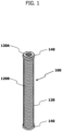
- FIG. 1 shows an example of a glued-in rod (GIR) 100 for joining wooden building components together.
- the GIR 100 may be an example of a metal joint.
- the GIR 100 may be used for building components including vertical structural members, such as posts, and horizontal structural members, such as beams and groundsills. Note that each of the horizontal and vertical structural members may be made of solid wood, laminated wood, or a combination thereof.
- the GIR 100 is made of, for example, a rolled steel for general structural applications, such as SS400, and has a small diameter portion 120 and two large diameter portions 140.
- the small diameter portion 120 has an elongated shape and a circular cross section.
- the large diameter portions 140 are fixed individually at locations spaced apart from each other in the longitudinal direction of the small diameter portion 120.
- the term "circular” refers not only to a perfect circle but also to a substantially and seemingly circular shape (the same applies to other shape-related terms herein).
- the entire length of the small diameter portion 120 is adapted such that the small diameter portion 120 can be entirely accommodated in a hole 210 extending in a building component 200 from one surface thereof in the direction perpendicular to the one surface. Furthermore, the outer diameter of the small diameter portion 120 is smaller than the inner diameter of the hole 210 such that a cylindrical gap GAP is created between the small diameter portion 120 and the inner periphery of the hole 210 when the GIR 100 is fitted into the hole 210.
- the gap GAP has dimensions that allow an adhesive such as an epoxy resin to flow therethrough in its longitudinal direction.
- the small diameter portion 120 has an internal thread 120A on a surface of one longitudinal end, more specifically, on a surface of the end to be located near the opening of the hole 210 of the building component 200.
- the internal thread 120A is adapted to receive a screwed-in bolt such as a hexagon socket head bolt or a hexagon bolt.
- the bolt may be an example of a fastener.
- the internal thread 120A extends in the longitudinal direction of the small diameter portion 120 in a center portion of the transverse cross section of the small diameter portion 120.
- the small diameter portion 120 has an external thread 120B extending in a spiral on the outer peripheral surface.
- the external thread 120B may be an example of irregularities for enhancing the adhesive bonding strength of the small diameter portion 120.
- the irregularities for enhancing the adhesive bonding strength of the small diameter portion 120 are not limited to the external thread 120B, but may be other forms formed on the outer peripheral surface of the small diameter portion 120. Other examples of such irregularities may include a plurality of thick annular rings and a plurality of protrusions and/or recesses.
- the large diameter portions 140 are coaxially fixed to the small diameter portion 120, by brazing or the like, individually at two locations spaced apart from each other in the longitudinal direction of the small diameter portion 120, preferably, at the opposite longitudinal ends of the small diameter portion 120.
- the large diameter portion 140 has an outer diameter corresponding to the inner diameter of the hole 210 of the building component 200, that is, has an outer diameter substantially equal to the inner diameter of the hole 210 so as to allow accurate positioning of the GIR 100 with respect to the hole 210 when the GIR 100 is fitted in the hole 210.
- the large diameter portions 140 function as positioning members to position the small diameter portion 120 coaxially with the hole 210 of the building component 200 when the GIR 100 is fitted in the hole 210, and thus, the GIR 100 can be positioned in the hole 210 with improved accuracy.
- each large diameter portion 140 is not limited to a thick cylindrical shape.
- the large diameter portion 140 may be a spring ring that is made of, for example, a cold rolled spring steel strip and has an outer diameter larger than the inner diameter of the hole 210 of the building component 200.
- the spring ring is elastically deformed to reduce its diameter while the GIR 100 is being fitted in the hole 210 of the building component 200, and is urged to expand its diameter by its elastic force after being fitted in the hole 210.
- the large diameter portion 140 is capable of retaining the position of the GIR 100 with respect to the hole 210.
- FIGS. 3A to 3D show an example of an embodiment of the present invention, namely a procedure for fixing the GIR 100 in one end surface of the building component 200 having an elongated shape.
- the hole 210 adapted to receive the GIR 100 fitted thereinto is formed on one longitudinal end surface of the building component 200 using a drill or the like.
- the entire length of the hole 210 may be equal to or longer than the entire length of the GIR 100 so that the GIR 100 can be entirely accommodated in the hole 210.
- an adhesive injection hole 220 and an adhesive fill check hole 230, both of which communicate with the hole 210, are formed in one side surface of the building component 200.
- the adhesive injection hole 220 and the adhesive fill check hole 230 are formed at positions that allow the holes 220, 230 communicate with the gap GAP, which is to be formed between the two large diameter portions 140 when the GIR 100 is fitted in the hole 210.
- the adhesive injection hole 220 is located near the bottom of the hole 210, and the adhesive fill check hole 230 is located near the opening of the hole 210.
- an adhesive may be input to fill an innermost portion of the hole 210 in this first step.
- the GIR 100 is fitted into the hole 210 of the building component 200 until reaching a predetermined position.
- the predetermined position may be a position that makes one surface of the upper large diameter portion 140 of the GIR 100 flush with the one end surface of the building component 200.
- the GIR 100 does not project from the one end surface of the building component 200. This ensures that when an additional building component is joined onto the one end surface of the building component 200, the GIR 100 does not interfere with the additional building component.
- the two large diameter portions 140 fixed to the opposite longitudinal ends of the small diameter portion 120 minimize the inclination of the central axis of the small diameter portion 120 with respect to the central axis of the hole 210 of the building component 200.
- an adhesive is injected from the adhesive injection hole 220.
- the adhesive injected from the adhesive injection hole 220 is supplied to the cylindrical gap GAP between the hole 210 of the building component 200 and the GIR 100 and flows toward the opening of the hole 210 having a lower flow resistance.
- the adhesive while flowing in the longitudinal direction of the gap GAP, the adhesive enters the valley of the external thread 120B formed on the outer peripheral surface of the small diameter portion 120 of the GIR 100.
- the fourth step it is checked whether the adhesive has flowed out from the adhesive fill check hole 230.
- the injection of the adhesive is continued until the adhesive flows out from the adhesive fill check hole 230, since such a state may be considered to indicate that the gap GAP has been filled up with the adhesive.
- the injection of the adhesive is stopped and the adhesive is cured until sufficiently hardened.
- the adhesive input to fill the gap GAP bonds the GIR 100 to the building component 200.
- the adhesive also fills the valley of the external thread 120B of the small diameter portion 120. This suppresses the movement of the GIR 100 in the longitudinal direction of the hole 210, and improves the fixing strength of the GIR 100 to the building component 200.
- the distance between the adhesive injection hole 220 and the small diameter portion 120 of the GIR 100 may be very small and may make it difficult to inject the adhesive into the gap GAP.
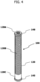
- the small diameter portion 120 may have a segment with a circumferential surface 120C having an outer diameter smaller than the outer diameter of the external thread 120B (that is, smaller than the outer diameter of the small diameter portion 120).
- the segment which is obtained by dividing the small diameter portion 120 in its longitudinal direction, extends in a predetermined length in the longitudinal direction of the small diameter portion 120 so as to face the opening of the adhesive injection hole 220. This makes it possible to increase the outer diameter of the small diameter portion 120 of the GIR 100, and thus, to use a bolt having a greater nominal diameter. Accordingly, the joining strength of the building component 200 can be improved.
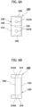
- a joining portion 160 having an external thread 160A on the outer peripheral surface may be integrally coupled onto a surface of the one end of the small diameter portion 120 of the GIR 100 instead of forming the internal thread 120A thereon, as shown in FIG. 5 .
- the joining portion 160 extends in the longitudinal direction of the small diameter portion 120 in a center portion of the transverse cross section of the small diameter portion 120 and has the external thread 160A at least in a distal end section thereof.
- the entire length of the joining portion 160 may be determined according to, for example, what building components are joined together with the GIR 100.
- the small diameter portion 120 of the GIR 100 may have the circumferential surface 120C as shown in FIG. 4 .
- a metal joining bracket adapted to be used in conjunction with the GIR 100 to join building components together.
- FIGS. 6Ato 6C show an example of a metal joining bracket 300.
- the metal joining bracket 300 is made of, for example, a rolled steel for general structural applications, such as SS400, and has a channel-shaped (C-shaped) body member 320 and three rectangular reinforcing members 340 for reinforcing the body member 320.
- the body member 320 has a top plate 322, a bottom plate 324, and a side plate 326, each of which has a rectangular shape.
- the top plate 322 and bottom plate 324 are joined by welding or the like onto the opposite (upper and lower) ends of the side plate 326 so as to be parallel with each other.
- the top plate 322 has insertion holes 322A, each adapted to receive the shank of a bolt, individually at two locations spaced apart from each other in the longitudinal direction of the top plate 322.
- the bolt may be an example of the fastener.
- the bottom plate 324 has insertion holes 324A, each adapted to receive the shank of a bolt, individually at two locations spaced apart from each other in the longitudinal direction of the bottom plate 324.
- the bolt may also be an example of the fastener.
- the reinforcing members 340 are joined onto the inner surfaces of the top plate 322, bottom plate 324 and side plate 326 of the body member 320 by welding or the like so that each of the plate surfaces of the reinforcing members 340 lies in a plane orthogonal to the top plate 322, bottom plate 324 and side plate 326. More specifically, the reinforcing members 340 are joined individually at the center and opposite ends of the top plate 322, bottom plate 324 and side plate 326, in a plan view. In the example shown in FIGS. 6A to 6C , each reinforcing member 340 has a width that partially fills the corresponding cross section of the channel-shaped opening. Note, however, that each reinforcing member 340 may entirely fill this cross section of the channel-shaped opening as long as the function of the tool for fastening the fastener may be enabled.
- FIG. 7 shows an example of a beam-dominated (beam-post) structure in which a beam BM is joined onto the upper surfaces of a pair of posts PT.
- Each post PT has an upper end portion with a stepped shape. Specifically, a center area of the upper end portion projects upward so that the metal joining brackets 300 may be fitted onto the opposite side surfaces of the post PT in the longitudinal direction of the beam BM.
- four GIRs 100 are fixed onto the lower step surfaces of the stepped portion of each post PT at the locations that are to face the insertion holes 324A of the bottom plates 324 of two metal joining brackets 300.
- eight GIRs 100 are fixed onto right and left areas of the lower surface of the beam BM at the locations that are to face the insertion holes 322A of the top plates 322 of the four metal joining brackets 300.
- the beam BM is placed on the upper surfaces of the pair of posts PT, and the metal joining brackets 300 are then fitted onto the opposite side surfaces of the stepped portion of each post PT.
- fasteners each including, for example, a hexagon socket head bolt and a washer are inserted through the insertion holes 322A, 324A of the metal joining brackets 300, and screwed into the internal threads 120A of the GIRs 100.
- a member for temporarily joining the posts PT and the beam BM may be used when the beam BM is placed on the upper surfaces of the posts PT.
- the first embodiment provides improved positioning accuracy of the GIRs 100 with respect to the posts PT and beam BM, and thus, provides improved joining accuracy between the beam BM and the posts PT, such as minimizing a position gap between the beam BM and each post PT.
- the resultant complete structure may have an improved accuracy and thus, has improved quality.
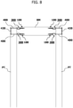
- FIG. 8 shows an example of a post-dominated (post-beam) structure in which a beam BM is joined onto side surfaces of a pair of posts PT.
- the beam BM has portions each having a stepped shape at the opposite longitudinal ends. Specifically, a center area of each of these end portions projects laterally outward so that the metal joining brackets 300 may be fitted onto the upper and lower surfaces of the beam BM.
- four GIRs 100 are fixed onto the lower step surfaces of the stepped portions of the beam BM at the locations that are to face the corresponding ones of the insertion holes 322A, 324A of two metal joining brackets 300.
- each post PT has through holes (not shown) in an upper end portion. Specifically, each of these through holes extends between opposite side surfaces of the post PT at the locations that are to face the remaining ones of the insertion holes 322A, 324A of the corresponding two metal joining brackets 300.
- the beam BM is placed between the pair of posts PT, and the metal joining brackets 300 are then fitted onto the upper and lower surfaces of the stepped portions of the beam BM.
- a fastener including, for example, a hexagon socket head bolt and a washer, is inserted through the insertion hole 322A or 324A of each metal joining bracket 300, and screwed into the internal thread 120A of the corresponding GIR 100.
- bolts 400 are inserted through the through holes of the posts PT from the surfaces, not facing the beam BM, of the posts PT so that the distal ends of the bolts 400 are inserted through the remaining ones of the insertion holes 322A, 324A of the metal joining brackets 300.
- fasteners each including, for example, a nut and a washer, are screwed onto the portions, projecting from these insertion holes 322A, 324A of the metal joining brackets 300, of the bolts 400.
- a member for temporarily joining the posts PT and the beam BM may be used when the beam BM is placed between the posts PT.
- metal plates 420 having insertion holes adapted to receive the shanks of the bolts 400 therethrough are attached onto the surfaces, not facing the beam BM, of the posts PT.
- the second embodiment provides improved positioning accuracy of the GIRs 100 with respect to the posts PT and beam BM, and thus, provides improved joining accuracy between the beam BM and the posts PT, such as minimizing a position gap between the beam BM and each post PT.
- the resultant complete structure may have an improved accuracy and thus, has improved quality.
- the GIRs 100 may be fixed in the upper end portion of each post PT.
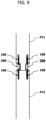
- FIG. 9 shows an example of a structure in which an upper post PT1 and a lower post PT2 are linearly joined together.
- the upper post PT1 has a lower end portion with a stepped shape. Specifically, a center area of the lower end portion projects downward so that the metal joining brackets 300 may be fitted onto the opposite side surfaces of the lower end portion.
- four GIRs 100 are fixed onto the upper step surfaces of the stepped portion of the post PT1 at the locations that are to face the insertion holes 322A of the top plates 322 of two metal joining brackets 300.
- four GIRs 100 are fixed onto the upper end surface of the lower post PT2 at the locations that are to face the insertion holes 324A of the bottom plates 324 of the two metal joining brackets 300.
- the post PT1 is placed on the post PT2 in a straight line with the lower end of the post PT1 in contact with the upper end of the post PT2, and the metal joining brackets 300 are then fitted onto the opposite side surfaces of the stepped portion of the upper post PT1.
- fasteners each including, for example, a hexagon socket head bolt and a washer are inserted through the insertion holes 322A, 324A of the metal joining brackets 300, and screwed into the internal threads 120A of the GIRs 100.
- a member for temporarily joining the posts PT1, PT2 may be used when the post PT1 is placed on the post PT2.
- the third embodiment provides improved positioning accuracy of the GIRs 100 with respect to the posts PT1, PT2, and thus, provides improved joining accuracy between the posts PT1, PT2, such as minimizing a position gap between the posts PT1, PT2.
- the resultant complete structure may have an improved accuracy and thus, has improved quality.
- application of the third embodiment is not limited to a structure in which the upper and lower posts are lineally joined together, but the third embodiment may also be applied to a structure in which two horizontal structural members, such as beams or groundsills, are lineally joined together.
- the GIRs 100 are not limited to the structures according to the first to third embodiments, but the GIRs 100 may be used in various locations of wooden buildings. Thus, when used in a wooden building, the GIRs 100 provides the resultant complete building an improved quality, such as an improved load-bearing capacity to resist external forces due to earthquakes, typhoons, and the like.
Landscapes
- Engineering & Computer Science (AREA)
- Architecture (AREA)
- Physics & Mathematics (AREA)
- Electromagnetism (AREA)
- Civil Engineering (AREA)
- Structural Engineering (AREA)
- General Engineering & Computer Science (AREA)
- Mechanical Engineering (AREA)
- Joining Of Building Structures In Genera (AREA)
Claims (9)
- Verfahren zum Befestigen einer Metallverbindung (100), die geeignet ist, in ein Loch (210) eingepasst zu werden, das in einer Endfläche eines Bauelements (200) mit einer länglichen Form ausgebildet ist, wobei die Metallverbindung (100) umfasst:einen Abschnitt (120) mit kleinem Durchmesser mit einer länglichen Form und einem Außendurchmesser, der kleiner als ein Innendurchmesser des Lochs (210) ist; undzwei Abschnitte (140) mit großem Durchmesser, die an dem Abschnitt (120) mit kleinem Durchmesser einzeln an zwei Stellen befestigt sind, die in einer Längsrichtung des Abschnitts (120) mit kleinem Durchmesser voneinander im Abstand angeordnet sind, wobei jeder Abschnitt (140) mit großem Durchmesser einen Außendurchmesser aufweist, der dem Innendurchmesser des Lochs (210) entspricht, wobei jeder der Abschnitte (140) mit großem Durchmesser einen Federring umfasst, wobei jeder Federring einen Außendurchmesser aufweist, der größer als der Innendurchmesser des Lochs (210) ist, wobei jeder Federring in der Lage ist, eine Position in Bezug auf das Loch durch elastische Kraft einzuhalten,wobei Unregelmäßigkeiten (120B) an einer äußeren Umfangsfläche des Abschnitts (120) mit kleinem Durchmesser in einem Teilabschnitt zwischen den beiden Abschnitten (140) mit großem Durchmesser ausgebildet sind; undwobei das Verfahren die Schritte umfasst:Ausbilden des Lochs (210) zum Einpassen der Metallverbindung (100) in der einen Endfläche des Bauelements (200), und auch Ausbilden eines Klebstoffeinspritzlochs (220) und eines Klebstofffüllkontrolllochs (230), die beide mit dem Loch (210) zum Einpassen der Metallverbindung (100) kommunizieren, in einer Seitenfläche des Bauelements (200);Einpassen der Metallverbindung (100) in das im Bauelement (200) ausgebildete Loch (210), bis eine vorbestimmte Position erreicht ist;Einspritzen eines Klebstoffs in das Klebstoffeinspritzloch (220), um den Klebstoff in einen Spalt (GAP) zwischen dem Abschnitt (120) mit kleinem Durchmesser der Metallverbindung (100) und dem Bauelement (200) zuzuführen; undPrüfen, ob der Klebstoff aus dem Klebstofffüllkontrollloch (230) herausgeflossen ist, und wenn der Klebstoff herausgeflossen ist, Anhalten des Einspritzens des Klebstoffs und Aushärten des Klebstoffs, bis der Klebstoff ausreichend gehärtet ist.
- Verfahren zum Befestigen einer Metallverbindung (100) nach Anspruch 1, wobei die Abschnitte (140) mit großem Durchmesser an gegenüberliegenden Längsenden des Abschnitts (120) mit kleinem Durchmesser befestigt werden.
- Verfahren zum Befestigen einer Metallverbindung (100) nach Anspruch 1, wobei die Unregelmäßigkeiten (120B) ein Außengewinde (160A) umfassen.
- Verfahren zum Befestigen einer Metallverbindung (100) nach Anspruch 1, wobei die Unregelmäßigkeiten (120B) eine Vielzahl von kranzförmigen Ringen umfassen.
- Verfahren zum Befestigen einer Metallverbindung (100) nach Anspruch 1, wobei die Unregelmäßigkeiten (120B) eine Vielzahl von Vorsprüngen und/oder Vertiefungen umfassen.
- Verfahren zum Befestigen einer Metallverbindung (100) nach Anspruch 1, wobei der Abschnitt (120) mit kleinem Durchmesser ein Segment mit einer Umfangsfläche aufweist, die einen Außendurchmesser aufweist, der kleiner als der Außendurchmesser des Abschnitts (120) mit kleinem Durchmesser ist, wobei das Segment durch Teilen des Teilabschnitts des Abschnitts (120) mit kleinem Durchmesser zwischen den beiden Abschnitten (140) mit großem Durchmesser in der Längsrichtung des Abschnitts (120) mit kleinem Durchmesser erhalten wird.
- Verfahren zum Befestigen einer Metallverbindung (100) nach Anspruch 1, wobei ein Innengewinde (120A) auf einer Fläche eines Längsendes des Abschnitts (120) mit kleinem Durchmesser ausgebildet wird.
- Verfahren zum Befestigen einer Metallverbindung (100) nach Anspruch 1, wobei ein Verbindungsabschnitt (160) mit einem Außengewinde (160A) in mindestens einem distalen Endteilabschnitt davon auf einer Fläche eines Längsendes des Abschnitts (120) mit kleinem Durchmesser verbunden ist.
- Verfahren zum Befestigen einer Metallverbindung (100) nach Anspruch 8, wobei der Verbindungsabschnitt (160) mit dem Abschnitt (120) mit kleinem Durchmesser einstückig verbunden ist.
Applications Claiming Priority (2)
| Application Number | Priority Date | Filing Date | Title |
|---|---|---|---|
| JP2016204720A JP6275798B1 (ja) | 2016-10-18 | 2016-10-18 | 接合金物 |
| PCT/JP2017/037594 WO2018074489A1 (ja) | 2016-10-18 | 2017-10-17 | 接合金物 |
Publications (4)
| Publication Number | Publication Date |
|---|---|
| EP3530828A1 EP3530828A1 (de) | 2019-08-28 |
| EP3530828A4 EP3530828A4 (de) | 2020-06-03 |
| EP3530828B1 true EP3530828B1 (de) | 2024-02-21 |
| EP3530828C0 EP3530828C0 (de) | 2024-02-21 |
Family
ID=61158399
Family Applications (1)
| Application Number | Title | Priority Date | Filing Date |
|---|---|---|---|
| EP17862674.3A Active EP3530828B1 (de) | 2016-10-18 | 2017-10-17 | Gelenkbeschlag |
Country Status (10)
| Country | Link |
|---|---|
| US (1) | US11352778B2 (de) |
| EP (1) | EP3530828B1 (de) |
| JP (1) | JP6275798B1 (de) |
| KR (1) | KR102374875B1 (de) |
| CN (1) | CN109844234B (de) |
| AU (1) | AU2017346916B2 (de) |
| CA (1) | CA3040639A1 (de) |
| NZ (1) | NZ752851A (de) |
| TW (1) | TWI763724B (de) |
| WO (1) | WO2018074489A1 (de) |
Cited By (1)
| Publication number | Priority date | Publication date | Assignee | Title |
|---|---|---|---|---|
| US12201524B2 (en) | 2016-11-21 | 2025-01-21 | Neovasc Tiara Inc. | Methods and systems for rapid retraction of a transcatheter heart valve delivery system |
Families Citing this family (10)
| Publication number | Priority date | Publication date | Assignee | Title |
|---|---|---|---|---|
| US10767684B1 (en) * | 2019-04-26 | 2020-09-08 | Solsera, Inc. | Flat roof mounting device |
| US12480302B2 (en) | 2020-02-07 | 2025-11-25 | Palm Dreamscapes QO ZB, LLC | Connection node for modular building structures |
| US10907342B1 (en) * | 2020-02-07 | 2021-02-02 | Assembly OSM, Inc. | Connection node for modular building structures |
| US12129645B2 (en) | 2020-02-07 | 2024-10-29 | Assembly OSM, Inc. | Connection node for modular building structures |
| EP4043737B1 (de) * | 2021-02-10 | 2024-11-27 | B/E Aerospace, Inc. | Verbinden konzentrischer elemente |
| WO2022212861A1 (en) * | 2021-04-01 | 2022-10-06 | Simpson Strong-Tie Company, Inc. | System for filling voids in glued-in-rod structures |
| CA3214804A1 (en) * | 2021-04-01 | 2022-10-06 | Simpson Strong-Tie Company, Inc. | System for filling voids in glued-in-rod structures |
| CN113833115A (zh) * | 2021-09-01 | 2021-12-24 | 广州市房屋开发建设有限公司 | 一种混凝土柱和木结构柱的连接节点及其施做方法 |
| CN115354758A (zh) * | 2022-09-23 | 2022-11-18 | 南通砼星建筑科技有限公司 | 预制构件连接件及其连接方式 |
| KR102760714B1 (ko) * | 2024-05-28 | 2025-02-03 | 경민산업주식회사 | 목재 결합구조 |
Citations (1)
| Publication number | Priority date | Publication date | Assignee | Title |
|---|---|---|---|---|
| US20160145854A1 (en) * | 2014-11-24 | 2016-05-26 | Scrimtec Japan Inc. Co., Ltd. | Joining structure |
Family Cites Families (55)
| Publication number | Priority date | Publication date | Assignee | Title |
|---|---|---|---|---|
| US36014A (en) * | 1862-07-29 | Improvement in bolts | ||
| US1243818A (en) * | 1917-03-20 | 1917-10-23 | Burns & Bassick Company | Method of producing hollow set-screws. |
| US2398984A (en) * | 1944-05-03 | 1946-04-23 | Floyd D Welch | Secret fastener |
| FR1434225A (fr) | 1965-01-25 | 1966-04-08 | Procédé et dispositif de soutènement par scellement, notamment des toits et des parements de mines | |
| DE7024434U (de) | 1970-06-30 | 1971-02-11 | Mueller P | Maueranker mit selbsttätiger Full und Haftstoff Auspressung an vorbestimm bare Zonen |
| DE2745438A1 (de) * | 1977-10-08 | 1979-04-12 | Fischer Artur Dr H C | Verankerung eines befestigungselementes |
| DE3009312A1 (de) * | 1980-03-11 | 1981-09-24 | Hilti AG, 9494 Schaan | Selbstbohrduebel |
| FI60278C (fi) * | 1980-10-20 | 1985-07-22 | Rakennusruuvi Oy | Faestdon |
| GB8323143D0 (en) * | 1983-08-27 | 1983-09-28 | Oxley R F | Tuning screw |
| US5145361A (en) * | 1984-12-04 | 1992-09-08 | Combustion Research, Inc. | Burner and method for metallurgical heating and melting |
| AT385306B (de) * | 1986-06-16 | 1988-03-25 | Pointner Ferdinand | Anker |
| DE3641502A1 (de) | 1986-12-04 | 1988-06-16 | Hilti Ag | Befestigungselement mit ankerstange und formkoerper |
| US5145301A (en) * | 1991-02-13 | 1992-09-08 | Akio Yamamoto | Nail sustainer |
| US5230191A (en) * | 1991-05-28 | 1993-07-27 | Paul Mayrand | Precast insulated concrete panel for prefabricated building structure |
| KR950008328B1 (ko) * | 1991-08-14 | 1995-07-27 | 야마모도 노부꼬 | 못 유지부재 |
| US6151856A (en) * | 1996-04-04 | 2000-11-28 | Shimonohara; Takeshige | Panels for construction and a method of jointing the same |
| JPH10311110A (ja) * | 1997-05-13 | 1998-11-24 | Sugimoto Kenchiku Kenkyusho:Kk | 建築物の接合構造 |
| JP3635520B2 (ja) | 1998-11-30 | 2005-04-06 | 秀利 大川 | 木材用接手、及び同接手を用いた木材の接合方法 |
| DE19955684A1 (de) * | 1999-11-19 | 2001-05-23 | Hilti Ag | Ankerstange für Verankerungen mit organischen und/oder anorganischen Mörtelmassen |
| JP2001214540A (ja) | 2000-02-04 | 2001-08-10 | Sunstar Eng Inc | 木ダボ接合構造 |
| DE10129441A1 (de) * | 2001-06-19 | 2003-01-02 | Fischer Artur Werke Gmbh | Verbundanker |
| US20040109738A1 (en) * | 2001-08-15 | 2004-06-10 | Ducker Andrew L. | Sealable fastener with sealant delivery passageway to circumferential sealant channel and method |
| US6902366B2 (en) * | 2001-08-15 | 2005-06-07 | Ducker, Iii Andrew L. | Sealable fastener with circumferential sealant channel and sealant delivery groove for delivering sealant into the circumferential sealant channel |
| CN100434603C (zh) * | 2002-08-06 | 2008-11-19 | 杨洪 | 一种建筑物绝缘隔震体系 |
| WO2006018908A1 (ja) * | 2004-08-18 | 2006-02-23 | Taisei Corporation | せん断力補強構造及びせん断力補強部材 |
| US7827759B1 (en) * | 2007-01-04 | 2010-11-09 | Audrey Barnes | Method of repairing concrete floors and system for same |
| US8398690B2 (en) * | 2007-02-07 | 2013-03-19 | Apex Biomedical Company, Llc | Rotationally asymmetric bone screw |
| US7802953B2 (en) * | 2007-03-16 | 2010-09-28 | Robert Stephen | Inset panel fastener |
| DE102007021132B4 (de) * | 2007-05-03 | 2009-01-29 | Gs Anlagen Und Immobilien Gmbh | Gestopfte Mutter, insbesondere Schweißmutter |
| US20100318130A1 (en) * | 2007-12-15 | 2010-12-16 | Parlato Brian D | Flexible rod assembly for spinal fixation |
| US20130008096A1 (en) * | 2010-04-01 | 2013-01-10 | Michael Griffiths | Utility pole |
| JP5718650B2 (ja) | 2011-01-05 | 2015-05-13 | 株式会社サカワ | 木製骨組材の接合方法 |
| US20120180423A1 (en) * | 2011-01-19 | 2012-07-19 | Seismic Design Toolbox, Inc. | Yielding Rod to Counter Seismic Activity |
| DE102011012955A1 (de) * | 2011-03-08 | 2012-09-13 | Karlsruher Institut für Technologie | Anker-Befestigungselement |
| DE102011005999A1 (de) * | 2011-03-23 | 2012-09-27 | Hilti Aktiengesellschaft | Spreizdübel |
| CN102858116A (zh) * | 2011-06-29 | 2013-01-02 | 深圳富泰宏精密工业有限公司 | 电子装置、其螺母钉及其组装方法 |
| JP5957257B2 (ja) * | 2012-03-27 | 2016-07-27 | 住友林業株式会社 | 木部材接合構造 |
| BE1020597A3 (nl) * | 2012-03-30 | 2014-01-07 | Vandenbempt Patent | Snelbouwsteen, evenals kunststof inzetstuk voor het vervaardigen van zulke snelbouwsteen. |
| DE202012005380U1 (de) * | 2012-06-01 | 2013-09-03 | Interroll-Holding Ag | Motorbetriebene Förderrolle für Förderanlagen zum Fördern von Behältern, Paletten und dergleichen |
| JP6001367B2 (ja) * | 2012-07-26 | 2016-10-05 | 株式会社駒井ハルテック | アンカーボルトの位置決め具 |
| CH706824B1 (de) * | 2012-08-14 | 2016-10-14 | S & P Clever Reinforcement Company Ag | Verankerungssystem für einen Traggrund im Bauwesen, sowie Verfahren zum Anbringen und Vorspannen eines Ankerstabes. |
| DE102012215587A1 (de) | 2012-09-03 | 2014-06-12 | Leichtbau-Zentrum Sachsen Gmbh | Lasteinleitungselement |
| DE102013204704B4 (de) | 2013-03-18 | 2015-02-26 | Confitt Gmbh | Werkzeuglos befestigbares Montageelement |
| US9127705B2 (en) * | 2013-11-29 | 2015-09-08 | Gregory Robert Silas | Concrete masonry anchor and method of fastening |
| CN104684308A (zh) * | 2013-11-29 | 2015-06-03 | 英业达科技有限公司 | 塑胶面板 |
| US9200661B2 (en) * | 2013-12-19 | 2015-12-01 | GM Global Technology Operations LLC | Flow drill screw |
| DE102014205448A1 (de) * | 2014-03-24 | 2015-09-24 | Mahle International Gmbh | Hülseneinsatz |
| JP5566553B1 (ja) * | 2014-04-23 | 2014-08-06 | 旭産商株式会社 | アンカー部材およびその施工方法 |
| JP2016037797A (ja) | 2014-08-08 | 2016-03-22 | 清水建設株式会社 | 柱梁接合構造 |
| WO2016090018A1 (en) * | 2014-12-02 | 2016-06-09 | Akp Consulting | Active compression devices, methods of assembly and methods of use |
| US10053863B2 (en) * | 2015-06-05 | 2018-08-21 | Eric Fenske | Multi-purpose anchor devices |
| US10443230B2 (en) * | 2016-02-10 | 2019-10-15 | Black & Decker, Inc. | Composite deck fastener |
| CN106436748A (zh) * | 2016-07-04 | 2017-02-22 | 中国电建集团华东勘测设计研究院有限公司 | 一种适用于山地光伏组件的岩锚基础结构及其施工方法 |
| CN106320564A (zh) * | 2016-09-06 | 2017-01-11 | 沈阳远大瑞福工程技术有限公司 | 凹框墙板定位连接装置 |
| GB2563452A (en) * | 2017-06-16 | 2018-12-19 | Www Opennshut Co Uk Ltd | Fixing device |
-
2016
- 2016-10-18 JP JP2016204720A patent/JP6275798B1/ja active Active
-
2017
- 2017-10-16 TW TW106135361A patent/TWI763724B/zh active
- 2017-10-17 CA CA3040639A patent/CA3040639A1/en active Pending
- 2017-10-17 EP EP17862674.3A patent/EP3530828B1/de active Active
- 2017-10-17 US US16/342,790 patent/US11352778B2/en active Active
- 2017-10-17 KR KR1020197009793A patent/KR102374875B1/ko active Active
- 2017-10-17 AU AU2017346916A patent/AU2017346916B2/en active Active
- 2017-10-17 NZ NZ752851A patent/NZ752851A/en unknown
- 2017-10-17 WO PCT/JP2017/037594 patent/WO2018074489A1/ja not_active Ceased
- 2017-10-17 CN CN201780058301.1A patent/CN109844234B/zh active Active
Patent Citations (1)
| Publication number | Priority date | Publication date | Assignee | Title |
|---|---|---|---|---|
| US20160145854A1 (en) * | 2014-11-24 | 2016-05-26 | Scrimtec Japan Inc. Co., Ltd. | Joining structure |
Cited By (1)
| Publication number | Priority date | Publication date | Assignee | Title |
|---|---|---|---|---|
| US12201524B2 (en) | 2016-11-21 | 2025-01-21 | Neovasc Tiara Inc. | Methods and systems for rapid retraction of a transcatheter heart valve delivery system |
Also Published As
| Publication number | Publication date |
|---|---|
| AU2017346916B2 (en) | 2022-11-24 |
| EP3530828A4 (de) | 2020-06-03 |
| WO2018074489A1 (ja) | 2018-04-26 |
| CN109844234A (zh) | 2019-06-04 |
| JP2018066163A (ja) | 2018-04-26 |
| NZ752851A (en) | 2021-12-24 |
| AU2017346916A1 (en) | 2019-05-02 |
| US20200056368A1 (en) | 2020-02-20 |
| JP6275798B1 (ja) | 2018-02-07 |
| CN109844234B (zh) | 2021-06-29 |
| TWI763724B (zh) | 2022-05-11 |
| CA3040639A1 (en) | 2018-04-26 |
| US11352778B2 (en) | 2022-06-07 |
| TW201825749A (zh) | 2018-07-16 |
| KR20190066013A (ko) | 2019-06-12 |
| EP3530828C0 (de) | 2024-02-21 |
| EP3530828A1 (de) | 2019-08-28 |
| KR102374875B1 (ko) | 2022-03-16 |
Similar Documents
| Publication | Publication Date | Title |
|---|---|---|
| EP3530828B1 (de) | Gelenkbeschlag | |
| EP2907932A1 (de) | Eingegossener ankerkanal mit subanker | |
| WO2015182714A1 (ja) | 柱と梁との接合構造及び方法 | |
| JP2018145786A (ja) | 管体結合構造およびユニット建物 | |
| KR100919701B1 (ko) | 프리캐스트 기둥과 프리캐스트 보의 접합구조 | |
| JP6351471B2 (ja) | 連結構造 | |
| JP2016132868A (ja) | 棒状金物 | |
| JP2011153437A (ja) | 補強金物 | |
| KR101433065B1 (ko) | 강-콘크리트 합성부재용 선조립 철골조 | |
| WO2021014616A1 (ja) | 鉄筋継手および鉄筋組立体、並びにプレキャスト鉄筋コンクリート体 | |
| JP2000248776A (ja) | 制震機構及びこれを使用した壁体 | |
| JP6894215B2 (ja) | 鉄骨複合部材およびその製造方法 | |
| KR101739081B1 (ko) | 조립형 프리캐스트 콘크리트 보강재를 구비한 비좌굴가새 | |
| KR20130081932A (ko) | 세그먼트용 체결장치 | |
| JP2017133186A (ja) | 鋼製地覆部の取付け構造 | |
| JP6921413B2 (ja) | 鉄筋継手および鉄筋組立体、並びにプレキャスト鉄筋コンクリート体 | |
| JP4704863B2 (ja) | 木質柱の柱脚部接合構造及びその柱脚部接合用具 | |
| JP5207070B2 (ja) | 被接合部材のコンクリート構造物への接合構造 | |
| JPH02112537A (ja) | 柱脚構造 | |
| WO2020234111A1 (en) | Device for joining building elements | |
| CN212452610U (zh) | 快速对接组件及快速对接机构 | |
| CN105937267A (zh) | 预埋模块 | |
| TWI604113B (zh) | 接合板預先結合之斜撐桿件 | |
| JP6174377B2 (ja) | セグメントの連結構造 | |
| GB2569186A (en) | Method for the reinforcement of masonry structures |
Legal Events
| Date | Code | Title | Description |
|---|---|---|---|
| STAA | Information on the status of an ep patent application or granted ep patent |
Free format text: STATUS: THE INTERNATIONAL PUBLICATION HAS BEEN MADE |
|
| PUAI | Public reference made under article 153(3) epc to a published international application that has entered the european phase |
Free format text: ORIGINAL CODE: 0009012 |
|
| STAA | Information on the status of an ep patent application or granted ep patent |
Free format text: STATUS: REQUEST FOR EXAMINATION WAS MADE |
|
| 17P | Request for examination filed |
Effective date: 20190508 |
|
| AK | Designated contracting states |
Kind code of ref document: A1 Designated state(s): AL AT BE BG CH CY CZ DE DK EE ES FI FR GB GR HR HU IE IS IT LI LT LU LV MC MK MT NL NO PL PT RO RS SE SI SK SM TR |
|
| AX | Request for extension of the european patent |
Extension state: BA ME |
|
| DAV | Request for validation of the european patent (deleted) | ||
| DAX | Request for extension of the european patent (deleted) | ||
| A4 | Supplementary search report drawn up and despatched |
Effective date: 20200430 |
|
| RIC1 | Information provided on ipc code assigned before grant |
Ipc: F16B 35/00 20060101ALN20200424BHEP Ipc: F16B 11/00 20060101ALN20200424BHEP Ipc: E04B 1/26 20060101AFI20200424BHEP Ipc: F16B 13/14 20060101ALI20200424BHEP Ipc: F16B 37/04 20060101ALI20200424BHEP Ipc: E04B 1/58 20060101ALI20200424BHEP Ipc: F16B 37/12 20060101ALN20200424BHEP |
|
| STAA | Information on the status of an ep patent application or granted ep patent |
Free format text: STATUS: EXAMINATION IS IN PROGRESS |
|
| 17Q | First examination report despatched |
Effective date: 20220325 |
|
| RIC1 | Information provided on ipc code assigned before grant |
Ipc: F16B 37/12 20060101ALN20230809BHEP Ipc: F16B 35/00 20060101ALN20230809BHEP Ipc: F16B 11/00 20060101ALN20230809BHEP Ipc: F16B 37/04 20060101ALI20230809BHEP Ipc: F16B 13/14 20060101ALI20230809BHEP Ipc: E04B 1/58 20060101ALI20230809BHEP Ipc: E04B 1/26 20060101AFI20230809BHEP |
|
| RIC1 | Information provided on ipc code assigned before grant |
Ipc: F16B 37/12 20060101ALN20230831BHEP Ipc: F16B 35/00 20060101ALN20230831BHEP Ipc: F16B 11/00 20060101ALN20230831BHEP Ipc: F16B 37/04 20060101ALI20230831BHEP Ipc: F16B 13/14 20060101ALI20230831BHEP Ipc: E04B 1/58 20060101ALI20230831BHEP Ipc: E04B 1/26 20060101AFI20230831BHEP |
|
| GRAP | Despatch of communication of intention to grant a patent |
Free format text: ORIGINAL CODE: EPIDOSNIGR1 |
|
| STAA | Information on the status of an ep patent application or granted ep patent |
Free format text: STATUS: GRANT OF PATENT IS INTENDED |
|
| INTG | Intention to grant announced |
Effective date: 20231017 |
|
| GRAS | Grant fee paid |
Free format text: ORIGINAL CODE: EPIDOSNIGR3 |
|
| GRAA | (expected) grant |
Free format text: ORIGINAL CODE: 0009210 |
|
| STAA | Information on the status of an ep patent application or granted ep patent |
Free format text: STATUS: THE PATENT HAS BEEN GRANTED |
|
| AK | Designated contracting states |
Kind code of ref document: B1 Designated state(s): AL AT BE BG CH CY CZ DE DK EE ES FI FR GB GR HR HU IE IS IT LI LT LU LV MC MK MT NL NO PL PT RO RS SE SI SK SM TR |
|
| REG | Reference to a national code |
Ref country code: GB Ref legal event code: FG4D |
|
| REG | Reference to a national code |
Ref country code: CH Ref legal event code: EP |
|
| REG | Reference to a national code |
Ref country code: IE Ref legal event code: FG4D |
|
| REG | Reference to a national code |
Ref country code: DE Ref legal event code: R096 Ref document number: 602017079417 Country of ref document: DE |
|
| U01 | Request for unitary effect filed |
Effective date: 20240221 |
|
| U07 | Unitary effect registered |
Designated state(s): AT BE BG DE DK EE FI FR IT LT LU LV MT NL PT SE SI Effective date: 20240227 |
|
| REG | Reference to a national code |
Ref country code: LT Ref legal event code: MG9D |
|
| PG25 | Lapsed in a contracting state [announced via postgrant information from national office to epo] |
Ref country code: IS Free format text: LAPSE BECAUSE OF FAILURE TO SUBMIT A TRANSLATION OF THE DESCRIPTION OR TO PAY THE FEE WITHIN THE PRESCRIBED TIME-LIMIT Effective date: 20240621 |
|
| PG25 | Lapsed in a contracting state [announced via postgrant information from national office to epo] |
Ref country code: GR Free format text: LAPSE BECAUSE OF FAILURE TO SUBMIT A TRANSLATION OF THE DESCRIPTION OR TO PAY THE FEE WITHIN THE PRESCRIBED TIME-LIMIT Effective date: 20240522 |
|
| PG25 | Lapsed in a contracting state [announced via postgrant information from national office to epo] |
Ref country code: RS Free format text: LAPSE BECAUSE OF FAILURE TO SUBMIT A TRANSLATION OF THE DESCRIPTION OR TO PAY THE FEE WITHIN THE PRESCRIBED TIME-LIMIT Effective date: 20240521 Ref country code: HR Free format text: LAPSE BECAUSE OF FAILURE TO SUBMIT A TRANSLATION OF THE DESCRIPTION OR TO PAY THE FEE WITHIN THE PRESCRIBED TIME-LIMIT Effective date: 20240221 |
|
| PG25 | Lapsed in a contracting state [announced via postgrant information from national office to epo] |
Ref country code: ES Free format text: LAPSE BECAUSE OF FAILURE TO SUBMIT A TRANSLATION OF THE DESCRIPTION OR TO PAY THE FEE WITHIN THE PRESCRIBED TIME-LIMIT Effective date: 20240221 |
|
| PG25 | Lapsed in a contracting state [announced via postgrant information from national office to epo] |
Ref country code: RS Free format text: LAPSE BECAUSE OF FAILURE TO SUBMIT A TRANSLATION OF THE DESCRIPTION OR TO PAY THE FEE WITHIN THE PRESCRIBED TIME-LIMIT Effective date: 20240521 Ref country code: IS Free format text: LAPSE BECAUSE OF FAILURE TO SUBMIT A TRANSLATION OF THE DESCRIPTION OR TO PAY THE FEE WITHIN THE PRESCRIBED TIME-LIMIT Effective date: 20240621 Ref country code: HR Free format text: LAPSE BECAUSE OF FAILURE TO SUBMIT A TRANSLATION OF THE DESCRIPTION OR TO PAY THE FEE WITHIN THE PRESCRIBED TIME-LIMIT Effective date: 20240221 Ref country code: GR Free format text: LAPSE BECAUSE OF FAILURE TO SUBMIT A TRANSLATION OF THE DESCRIPTION OR TO PAY THE FEE WITHIN THE PRESCRIBED TIME-LIMIT Effective date: 20240522 Ref country code: ES Free format text: LAPSE BECAUSE OF FAILURE TO SUBMIT A TRANSLATION OF THE DESCRIPTION OR TO PAY THE FEE WITHIN THE PRESCRIBED TIME-LIMIT Effective date: 20240221 |
|
| PG25 | Lapsed in a contracting state [announced via postgrant information from national office to epo] |
Ref country code: PL Free format text: LAPSE BECAUSE OF FAILURE TO SUBMIT A TRANSLATION OF THE DESCRIPTION OR TO PAY THE FEE WITHIN THE PRESCRIBED TIME-LIMIT Effective date: 20240221 |
|
| PG25 | Lapsed in a contracting state [announced via postgrant information from national office to epo] |
Ref country code: PL Free format text: LAPSE BECAUSE OF FAILURE TO SUBMIT A TRANSLATION OF THE DESCRIPTION OR TO PAY THE FEE WITHIN THE PRESCRIBED TIME-LIMIT Effective date: 20240221 |
|
| PG25 | Lapsed in a contracting state [announced via postgrant information from national office to epo] |
Ref country code: SM Free format text: LAPSE BECAUSE OF FAILURE TO SUBMIT A TRANSLATION OF THE DESCRIPTION OR TO PAY THE FEE WITHIN THE PRESCRIBED TIME-LIMIT Effective date: 20240221 |
|
| U20 | Renewal fee for the european patent with unitary effect paid |
Year of fee payment: 8 Effective date: 20240906 |
|
| PG25 | Lapsed in a contracting state [announced via postgrant information from national office to epo] |
Ref country code: CZ Free format text: LAPSE BECAUSE OF FAILURE TO SUBMIT A TRANSLATION OF THE DESCRIPTION OR TO PAY THE FEE WITHIN THE PRESCRIBED TIME-LIMIT Effective date: 20240221 |
|
| PG25 | Lapsed in a contracting state [announced via postgrant information from national office to epo] |
Ref country code: SK Free format text: LAPSE BECAUSE OF FAILURE TO SUBMIT A TRANSLATION OF THE DESCRIPTION OR TO PAY THE FEE WITHIN THE PRESCRIBED TIME-LIMIT Effective date: 20240221 |
|
| PG25 | Lapsed in a contracting state [announced via postgrant information from national office to epo] |
Ref country code: SM Free format text: LAPSE BECAUSE OF FAILURE TO SUBMIT A TRANSLATION OF THE DESCRIPTION OR TO PAY THE FEE WITHIN THE PRESCRIBED TIME-LIMIT Effective date: 20240221 Ref country code: SK Free format text: LAPSE BECAUSE OF FAILURE TO SUBMIT A TRANSLATION OF THE DESCRIPTION OR TO PAY THE FEE WITHIN THE PRESCRIBED TIME-LIMIT Effective date: 20240221 Ref country code: RO Free format text: LAPSE BECAUSE OF FAILURE TO SUBMIT A TRANSLATION OF THE DESCRIPTION OR TO PAY THE FEE WITHIN THE PRESCRIBED TIME-LIMIT Effective date: 20240221 Ref country code: CZ Free format text: LAPSE BECAUSE OF FAILURE TO SUBMIT A TRANSLATION OF THE DESCRIPTION OR TO PAY THE FEE WITHIN THE PRESCRIBED TIME-LIMIT Effective date: 20240221 |
|
| REG | Reference to a national code |
Ref country code: DE Ref legal event code: R097 Ref document number: 602017079417 Country of ref document: DE |
|
| PLBE | No opposition filed within time limit |
Free format text: ORIGINAL CODE: 0009261 |
|
| STAA | Information on the status of an ep patent application or granted ep patent |
Free format text: STATUS: NO OPPOSITION FILED WITHIN TIME LIMIT |
|
| PGFP | Annual fee paid to national office [announced via postgrant information from national office to epo] |
Ref country code: NO Payment date: 20241015 Year of fee payment: 8 |
|
| 26N | No opposition filed |
Effective date: 20241122 |
|
| PGFP | Annual fee paid to national office [announced via postgrant information from national office to epo] |
Ref country code: CH Payment date: 20241107 Year of fee payment: 8 |
|
| PG25 | Lapsed in a contracting state [announced via postgrant information from national office to epo] |
Ref country code: MC Free format text: LAPSE BECAUSE OF FAILURE TO SUBMIT A TRANSLATION OF THE DESCRIPTION OR TO PAY THE FEE WITHIN THE PRESCRIBED TIME-LIMIT Effective date: 20240221 |
|
| PGFP | Annual fee paid to national office [announced via postgrant information from national office to epo] |
Ref country code: GB Payment date: 20250919 Year of fee payment: 9 |
|
| PG25 | Lapsed in a contracting state [announced via postgrant information from national office to epo] |
Ref country code: IE Free format text: LAPSE BECAUSE OF NON-PAYMENT OF DUE FEES Effective date: 20241017 |
|
| U20 | Renewal fee for the european patent with unitary effect paid |
Year of fee payment: 9 Effective date: 20250919 |
|
| REG | Reference to a national code |
Ref country code: CH Ref legal event code: U11 Free format text: ST27 STATUS EVENT CODE: U-0-0-U10-U11 (AS PROVIDED BY THE NATIONAL OFFICE) Effective date: 20251111 |