EP4043737B1 - Verbinden konzentrischer elemente - Google Patents
Verbinden konzentrischer elemente Download PDFInfo
- Publication number
- EP4043737B1 EP4043737B1 EP21461511.4A EP21461511A EP4043737B1 EP 4043737 B1 EP4043737 B1 EP 4043737B1 EP 21461511 A EP21461511 A EP 21461511A EP 4043737 B1 EP4043737 B1 EP 4043737B1
- Authority
- EP
- European Patent Office
- Prior art keywords
- void
- adhesive
- bonding
- faces
- face
- Prior art date
- Legal status (The legal status is an assumption and is not a legal conclusion. Google has not performed a legal analysis and makes no representation as to the accuracy of the status listed.)
- Active
Links
Images
Classifications
-
- F—MECHANICAL ENGINEERING; LIGHTING; HEATING; WEAPONS; BLASTING
- F16—ENGINEERING ELEMENTS AND UNITS; GENERAL MEASURES FOR PRODUCING AND MAINTAINING EFFECTIVE FUNCTIONING OF MACHINES OR INSTALLATIONS; THERMAL INSULATION IN GENERAL
- F16B—DEVICES FOR FASTENING OR SECURING CONSTRUCTIONAL ELEMENTS OR MACHINE PARTS TOGETHER, e.g. NAILS, BOLTS, CIRCLIPS, CLAMPS, CLIPS OR WEDGES; JOINTS OR JOINTING
- F16B11/00—Connecting constructional elements or machine parts by sticking or pressing them together, e.g. cold pressure welding
- F16B11/006—Connecting constructional elements or machine parts by sticking or pressing them together, e.g. cold pressure welding by gluing
- F16B11/008—Connecting constructional elements or machine parts by sticking or pressing them together, e.g. cold pressure welding by gluing of tubular elements or rods in coaxial engagement
-
- B—PERFORMING OPERATIONS; TRANSPORTING
- B29—WORKING OF PLASTICS; WORKING OF SUBSTANCES IN A PLASTIC STATE IN GENERAL
- B29C—SHAPING OR JOINING OF PLASTICS; SHAPING OF MATERIAL IN A PLASTIC STATE, NOT OTHERWISE PROVIDED FOR; AFTER-TREATMENT OF THE SHAPED PRODUCTS, e.g. REPAIRING
- B29C66/00—General aspects of processes or apparatus for joining preformed parts
- B29C66/50—General aspects of joining tubular articles; General aspects of joining long products, i.e. bars or profiled elements; General aspects of joining single elements to tubular articles, hollow articles or bars; General aspects of joining several hollow-preforms to form hollow or tubular articles
- B29C66/51—Joining tubular articles, profiled elements or bars; Joining single elements to tubular articles, hollow articles or bars; Joining several hollow-preforms to form hollow or tubular articles
- B29C66/53—Joining single elements to tubular articles, hollow articles or bars
- B29C66/534—Joining single elements to open ends of tubular or hollow articles or to the ends of bars
- B29C66/5344—Joining single elements to open ends of tubular or hollow articles or to the ends of bars said single elements being substantially annular, i.e. of finite length, e.g. joining flanges to tube ends
-
- B—PERFORMING OPERATIONS; TRANSPORTING
- B29—WORKING OF PLASTICS; WORKING OF SUBSTANCES IN A PLASTIC STATE IN GENERAL
- B29C—SHAPING OR JOINING OF PLASTICS; SHAPING OF MATERIAL IN A PLASTIC STATE, NOT OTHERWISE PROVIDED FOR; AFTER-TREATMENT OF THE SHAPED PRODUCTS, e.g. REPAIRING
- B29C65/00—Joining or sealing of preformed parts, e.g. welding of plastics materials; Apparatus therefor
- B29C65/48—Joining or sealing of preformed parts, e.g. welding of plastics materials; Apparatus therefor using adhesives, i.e. using supplementary joining material; solvent bonding
- B29C65/4805—Joining or sealing of preformed parts, e.g. welding of plastics materials; Apparatus therefor using adhesives, i.e. using supplementary joining material; solvent bonding characterised by the type of adhesives
- B29C65/483—Reactive adhesives, e.g. chemically curing adhesives
- B29C65/485—Multi-component adhesives, i.e. chemically curing as a result of the mixing of said multi-components
-
- B—PERFORMING OPERATIONS; TRANSPORTING
- B29—WORKING OF PLASTICS; WORKING OF SUBSTANCES IN A PLASTIC STATE IN GENERAL
- B29C—SHAPING OR JOINING OF PLASTICS; SHAPING OF MATERIAL IN A PLASTIC STATE, NOT OTHERWISE PROVIDED FOR; AFTER-TREATMENT OF THE SHAPED PRODUCTS, e.g. REPAIRING
- B29C65/00—Joining or sealing of preformed parts, e.g. welding of plastics materials; Apparatus therefor
- B29C65/48—Joining or sealing of preformed parts, e.g. welding of plastics materials; Apparatus therefor using adhesives, i.e. using supplementary joining material; solvent bonding
- B29C65/52—Joining or sealing of preformed parts, e.g. welding of plastics materials; Apparatus therefor using adhesives, i.e. using supplementary joining material; solvent bonding characterised by the way of applying the adhesive
- B29C65/54—Joining or sealing of preformed parts, e.g. welding of plastics materials; Apparatus therefor using adhesives, i.e. using supplementary joining material; solvent bonding characterised by the way of applying the adhesive between pre-assembled parts
- B29C65/542—Joining or sealing of preformed parts, e.g. welding of plastics materials; Apparatus therefor using adhesives, i.e. using supplementary joining material; solvent bonding characterised by the way of applying the adhesive between pre-assembled parts by injection
-
- B—PERFORMING OPERATIONS; TRANSPORTING
- B29—WORKING OF PLASTICS; WORKING OF SUBSTANCES IN A PLASTIC STATE IN GENERAL
- B29C—SHAPING OR JOINING OF PLASTICS; SHAPING OF MATERIAL IN A PLASTIC STATE, NOT OTHERWISE PROVIDED FOR; AFTER-TREATMENT OF THE SHAPED PRODUCTS, e.g. REPAIRING
- B29C66/00—General aspects of processes or apparatus for joining preformed parts
- B29C66/01—General aspects dealing with the joint area or with the area to be joined
- B29C66/05—Particular design of joint configurations
- B29C66/10—Particular design of joint configurations particular design of the joint cross-sections
- B29C66/11—Joint cross-sections comprising a single joint-segment, i.e. one of the parts to be joined comprising a single joint-segment in the joint cross-section
- B29C66/112—Single lapped joints
- B29C66/1122—Single lap to lap joints, i.e. overlap joints
Definitions
- This disclosure relates to the bonding of concentric elements that form part of a component, in particular to the design of concentric elements to achieve an improved bond between them, and a method of bonding concentric elements.
- first and second elements are to be joined where the first element comprises a first bonding portion including a first bonding face, and the second element comprises a second bonding portion including a second bonding face, and the first and second elements are so configured that when bonded together the first bonding portion is at least partially surrounded by the second bonding portion, the first and second bonding faces are close to and face towards each other, and the first and second bonding faces are substantially parallel with each other. This may be described as the bonding of first and second concentric elements.
- first and second elements are cylindrical tubes which are to be bonded with one of the tubes at least partially within the other.
- first tube to have an outer diameter which is a little, for example in the range of about 0.5 mm to 2.0 mm, smaller than the inner diameter of the second tube.
- at least a portion of the radially outer surface of the first tube is the first bonding face
- at least a portion of the radially inner surface of the second tube is the second bonding face.
- a known technique is that a layer of adhesive is applied to one or both of the first bonding face and the second bonding face and the first bonding portion is then pushed into the second bonding portion until the desired relative positions of the first and second elements is achieved. This may be a position in which a part of the first element interferes with a part of the second element and prevents the first bonding portion being pushed further into the second bonding portion. The adhesive is then left to set/cure.
- More complex first and second concentric elements include first and second bonding portions and other portions with other functions. Again, however, when they are to be bonded the first bonding portions of the first element is surrounded by the second bonding portion of the second element and they are known to be joined in the same way as described for the basic example above.
- US 2020/056368 A1 relates to a metal joint for use in glued-in rod connection.
- a component comprising a first concentric element and a second concentric element in which the first and second concentric elements are positioned relative to each other in the positions in which they are to be bonded together.
- the first concentric element comprises a first bonding portion with a first bonding face and the second concentric element comprises a second bonding portion with a second bonding face, a first passage, and a second passage.
- the second bonding portion partially surrounds the first bonding portion and the first and second bonding faces face each other.
- the first and second bonding faces comprise a first and second void face respectively, and between them / collectively the first and second bonding faces further comprise an alpha plug having an alpha plug face, a beta plug having a beta plug face, an alpha bearing face and a beta bearing face.
- the alpha plug face is in sliding or close contact with the alpha bearing face and the beta plug face is in sliding contact with the beta baring face, the alpha plug is integral with one of the first or second void faces and the alpha bearing face is integral with the other of the first or second void faces.
- the beta plug is integral with one of the first or second void faces and the beta bearing face is integral with the other of the first or second void faces.
- the alpha and beta plugs and the first and second void faces collectively define a void.
- the first and second passages each extend through the second concentric element from a mouth which opens onto the void to a mouth in an accessible surface of the second concentric element.
- One or both of the first and second concentric elements comprises an adhesive guide means, in which the adhesive guide means is a fin extending from one of the first and second void faces toward the other of the first and second void faces, and the fin has a first end at or adjacent the alpha plug, a second end at or adjacent the beta plug, and the fin extends between its first and second ends in an at least partially non-linear direction, and the fin defines a path between the mouth of the first passage onto the void and the mouth of the second passage onto the void.
- the first and second bonding faces can be comprised of one or more face portions. These face portions can be continuous and joined by corners or folds.
- the first and second void faces are constituents of the first and second bonding faces respectively.
- the void defined by the first and second void faces and the alpha and beta plugs is a void into which adhesive will be injected when the first and second concentric elements are bonded together.
- the void partially surrounds the first bonding portion, and the thickness of the void (along the shortest path from the first void face to the second void face) is determined by the thickness of the alpha and beta plugs in the same direction. The thickness of the void determines the thickness of the adhesive layer once the first and second concentric elements have been bonded together.
- the alpha plug face / alpha bearing face and beta plug face / beta bearing face are so configured that the sliding fit between them is sufficiently tight that once adhesive is injected into the void, it does not flow between the alpha / beta plug face and the alpha / beta bearing faces. How tight that sliding fit is required to be will depend in part upon the viscosity of the adhesive to be injected into the void.
- reference to injected in connection with the adhesive is to be understood to be reference to any method of introducing an adhesive in liquid or paste form into the void.
- An accessible face of the second concentric element is one that a human user or automated assembly apparatus can access when the first and second concentric elements are positioned relative to each other ready for bonding to each other.
- the first bonding face comprises the alpha and beta plugs and first void face with the first void face extending between the alpha and beta plugs
- the second bonding face comprises the alpha and beta bearing faces and second void face with the second void face extending between the alpha and beta bearing faces.
- the second bonding face comprises the alpha and beta plugs and second void face with the second void face extending between the alpha and beta plugs
- the first bonding face comprises the alpha and beta bearing faces and first void face with the first void face extending between the alpha and beta bearing faces.
- the component / first and second concentric elements of the present disclosure are advantageous because the adhesive for bonding the first and second concentric elements is injected into the void with the first and second concentric elements in the relative positions they are intended to be in. As a result, there is no need to move the first and second concentric elements once the adhesive has been applied and the risk of extruded beads of excess adhesive, which can impair the functionality of the component once fully constructed, are minimised.
- a further advantage of the component / first and second concentric elements of the present disclosure is that because the first and second concentric elements are not moved relative each other once adhesive has been injected into the void, there is a minimum risk that the adhesive will unevenly distribute itself within the joint between the first and second concentric elements, potentially leading to weak zones in the bond. Furthermore, any weakening of the adhesive by introduction of shear stresses into the adhesive can be avoided.
- a further advantage of the component / first and second concentric elements of the present disclosure is that the injection of the adhesive through one of the passages until the adhesive reaches the other passage is that this assists in forming a continuous and uniform layer of adhesive between the bonding portions of the first and second concentric elements. This can maximise the strength of the bond between the first and second concentric elements.
- the first and second bonding portions are so configured that the first bonding portion is physically prevented from extending into the second bonding portion by more than a predetermined distance. In some embodiments the prevention is a result of interference between a part of the first concentric element and a part of the second concentric element.
- the first and second bonding portions are so configured that when the first bonding portion is partially surrounded by the second bonding portion, the only movement the first bonding portion can make relative to the second bonding portion is movement between a position where the first bonding portion is not partially surrounded by the second bonding portion and the position in which the first bonding portion extends a predetermined distance into the second bonding portion.
- This configuration is advantageous because it minimises the risk of any movement between the first and second concentric elements once the adhesive has been injected into the void. Such movement whilst the adhesive is setting can impair the strength of the bond after the adhesive has set / cured.
- the mouth of the first passage onto the void and the mouth of the second passage onto the void are spaced from each other, in that one mouth is in the alpha plug or nearer the alpha plug than the beta plug, and the other mouth is in the beta plug or nearer the beta plug than the alpha plug.
- the spacing of the mouths onto the void assists in maximising the filling of the void with adhesive and helps to avoid air bubbles being trapped in the void by the adhesive.
- the adhesive guide means extends across the most direct path through the void from the mouth of the first passage onto the void and the mouth of the second passage onto the void.
- the adhesive guide means help in directing the flow of adhesive to all parts of the void and seeks to minimise the quantity of adhesive travelling straight from the mouth onto the void through which the adhesive is injected to the mouth onto the void by which the adhesive can exit.
- the adhesive guide means extends from the surface of one of the first and second void faces toward the other of the first and second void faces, and at least a part of the adhesive guide means has the form of a helix.
- the mouth of the first passage onto the void is close to one end of the fin, and the mouth of the second passage is close to the other end of the fin.
- the fin significantly influences the flow of the adhesive between the mouths onto the void.
- the adhesive guide means is fixed to one of the first and second void faces, and is in sliding contact with the other of the first and second void faces. In alternative embodiments of the above embodiments, the adhesive guide means is fixed to one of the first and second void faces, and is spaced from the other of the first and second void faces.
- the component is an auto drain valve
- the first concentric element is a bowl and the second concentric element is a connector
- a method of bonding a first concentric element and a second concentric element of a component according to the first aspect of the present disclosure in which an adhesive applicator is engaged with the mouth of one of the first and second passage in an accessible surface of the second concentric element, the applicator is actuated and injects adhesive into passage with which the applicator is engaged and into the void until a predetermined event occurs, and actuation of the applicator is then stopped.
- the predetermined event is one of:
- the mouth onto the void associated with the passage with which the adhesive applicator is engaged is vertically lower than the mouth onto the void of the passage not engaged with the applicator. This arrangement assists in the adhesive excluding as much air as possible from the void as the adhesive is injected into the void because the adhesive will fill the void from its bottom as it is orientated during the adhesive injection.
- the adhesive is one of an acrylic adhesive, methyl methacrylate adhesive, or an epoxy adhesive.
- adhesives are well known and can be selected to suit the materials of the first and second bonding portions of the first and second concentric elements.
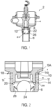
- an auto drain valve 2 comprises a bowl 4, a connector 6, and a check valve 22.
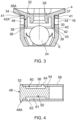
- the auto drain valve of Figure 2 is of a known configuration and bonded using a known method.
- the bowl 4 includes a (first) bonding portion 8 with a (first) bonding face formed from faces 10 and 10A.
- the connector 6 includes a (second) bonding portion 12 with a (second) bonding face formed from faces 14 and 14A.
- Figure 2 shows the result of bonding the bonding portions 8, 12 to each other using the known technique of applying an adhesive 16 to one or both of bonding faces 10, 14 and then pushing the bonding portion 10 of the bowl 4 into the bonding portion 12 of the connector 6 until face 10A abuts face 14A.
- the outside excess adhesive bead 18 is unsightly but does not affect the function of the auto drain valve 2. It is also relatively easy to remove before the adhesive 16 sets/cures.
- the inside excess adhesive bead 20 is not easy to remove and can be detrimental to the correct functioning of the auto drain valve 2. It can be detrimental because the excess adhesive bead 20 is close to a check valve 22, and in particular close to a free sphere 24 which comprises a part of the check valve 22.
- the sphere 24 is free to move in the void between the fixed element 26 of the check valve 22 and the end of a conduit 28 closest to the fixed element 26 and may thus come into contact with the excess adhesive bead 20 before the adhesive sets. Such contact is likely to affect the function of the check valve if it functions at all. This is clearly undesirable.
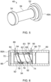
- the bowl 4 has a (first) bonding portion 30 with a (first) bonding face 32.
- the bonding face 32 is comprised of an alpha plug 34 with an alpha plug face 37, a beta plug 36 with a beta plug face 39, and a void face 38.
- the (second) bonding portion 40 of the connector 6 includes a (second) bonding face formed from void face 42/42A, alpha bearing face 41, and beta bearing face 43.
- the bonding portion 40 of the connector 6 further includes first and second passages 44, 46. Both of the passages 44, 46 extend from an outside face of the connector 6 to the void face 42 of the connector 6.
- the passages are spaced from each other and, in the example shown in Figure 3 are located on opposite sides of the bonding portion 40. This has the result that the passages 44, 46 are substantially co-axial. This makes it easy and efficient to form the passages with a single drilling operation.
- the passages 44, 46 may have a different spacing from each other and may not be co-axial.
- the beta plug face 39 is a sliding fit with the beta bearing face 43.
- the bonding portion 30 of the bowl 4 can be pushed into the bonding portion 40 of the connector 6 until the alpha plug face 37 abuts the beta bearing face 41.
- the first void face 38/38A is substantially parallel to and spaced from the void face 42/42A of the connector 6.
- the beta plug 36 assists in centring the bonding portion 30 within the bonding portion 40.
- a void for adhesive is defined by the alpha plug 34, the first void face 38, 38A, the beta plug 36, and the second void face 42, 42A.
- an adhesive 16 is injected/introduced by an operator into the void via an entry passage which is one of the passages 44, 46.
- the adhesive 16 is injected from a nozzle or other suitable applicator (not shown) which fits into the entry passage.
- the adhesive 16 is pressurised by the applicator with the result that it flows from the entry passage to the exit passage, which is the other of passages 44, 46, via the void.
- FIGS. 4 and 5 show an example of the interaction of a first and second bonding portion 48, 58 of first and second concentric elements. For clarity, no other part of the first and second concentric elements is shown.
- the principles associated with the first and second bonding portions 48, 58 can readily be incorporated in various concentric elements.
- the first bonding portion 48 has a first bonding face 50 comprised of an alpha plug 52, a beta plug 54, and a first void face 56.
- the second bonding portion 58 has a second bonding face 60 including a second void face 61 and a first and second passage 62, 64.
- the alpha and beta plug faces and the alpha and beta bearing faces associated with first and second bonding faces 50, 60 respectively are not shown.
- the first and second passage 62, 64 are located on opposite sides of the second bonding portion 58 and spaced longitudinally along the second bonding portion 58 to achieve a near maximum distance from the first passage 62 to the second passage 64 via the void.
- the alpha plug 52 and beta plug 54 centre the first bonding portion 48 within the second bonding portion 58.
- the first bonding portion 48 can be pushed into the second bonding portion 58 until a flange 48A of the first bonding portion 48 abuts the second bonding portion 58.
- first bonding portion 48 to the second bonding portion 58 adhesive (not shown) is injected into the void between alpha and beta plugs 52, 54 and first and second void faces 56, 61 via an entry passage which is one of the passages 62, 64 by an operator.
- the adhesive is injected from a nozzle or other suitable applicator (not shown) which fits into the entry passage.
- the adhesive is pressurised with the result that it flows from the entry passage to the exit passage, which is the other of passages 62, 64, via the void.
- the exit passage which is the other of passages 62, 64, via the void.
- the entry and exit passages are so positioned relative to each other that the adhesive enters the void at or near the lowest portion of that void, and the adhesive has to flow upwards to reach the exit passage.
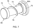
- the first bonding portion 66 has a first bonding face 68 comprised of an alpha plug 70, and beta plug 72 and a void face 74.
- the second bonding portion 80 has a second bonding face 82 including a second void face 83 and a first and second passage 84, 86.
- the alpha and beta plug faces and the alpha and beta bearing faces associated with first and second bonding faces 568, 82 respectively are not shown.
- the first and second passage 84, 86 are on the same side of the second bonding portion 80 and spaced longitudinally along the second bonding portion 80.
- a helical fin 76 Upstanding from the first void face 74 of the first bonding portion 66 is a helical fin 76.
- the helical fin 76 extends radially from the recessed face 74 to a fin edge 78.
- the fin edge 78 is spaced from the second void face 83 when the first bonding portion 66 is within the second bonding portion 80.
- the fin edge 78 can be in sliding contact with the second void face 83 when the first bonding portion 66 is within the second bonding portion 80.
- the alpha plug 70 and beta plug 72 centre the first bonding portion 66 within the second bonding portion 80.
- the first bonding portion 66 can be pushed into the second bonding portion 80 until a flange 66A of the first bonding portion 66 abuts the second bonding portion 80.
- adhesive (not shown) is injected into the void via an entry passage 84 by an operator.
- the adhesive is injected from a nozzle or other suitable applicator (not shown) and as represented by arrow 88.
- the nozzle fits into the entry passage 84 and the adhesive is pressurised by the applicator with the result that it flows from the entry passage 84 to the exit passage 86, via the void.
- the fin 76 causes a proportion of the introduced adhesive to travel helically around the first void face 74 as represented by arrows 92.
- the remainder of the adhesive passes between the fin edge 78 and the second void face 83 as represented by arrows 94.
- the proportion of the adhesive that travels helically from the entry passage 84 to the exit passage 86 is determined by the viscosity of the adhesive and the size of the gap between the fin edge 78 and the second void face 83. The higher the viscosity and / or the smaller the size of the gap between the fin edge 78 and the second void face 83, the greater the proportion of adhesive that travels helically around the recessed face 74.
Landscapes
- Engineering & Computer Science (AREA)
- Mechanical Engineering (AREA)
- Chemical & Material Sciences (AREA)
- Chemical Kinetics & Catalysis (AREA)
- General Chemical & Material Sciences (AREA)
- General Engineering & Computer Science (AREA)
- Adhesives Or Adhesive Processes (AREA)
Claims (14)
- Komponente, umfassend ein erstes konzentrisches Element und ein zweites konzentrisches Element, wobeidas erste und das zweite konzentrische Element in den Positionen, in denen sie miteinander zu verbinden sind, relativ zueinander positioniert werden,das erste konzentrische Element einen ersten Verbindungsabschnitt (48) mit einer ersten Verbindungsfläche (50) umfasst,das zweite konzentrische Element einen zweiten Verbindungsabschnitt (58) mit einer zweiten Verbindungsfläche (60), einem ersten Kanal (62) und einem zweiten Kanal (64) umfasst,der zweite Verbindungsabschnitt (58) den ersten Verbindungsabschnitt (48) teilweise umgibt und die erste und die zweite Verbindungsfläche (50, 60) einander zugewandt sind,die erste und die zweite Verbindungsfläche (50, 60) eine erste bzw. zweite Hohlraumfläche (56, 61) umfassen, wobei die erste und die zweite Verbindungsfläche (50, 60) zusammen einen Alpha-Stopfen (52), der eine Alpha-Stopfenfläche aufweist, einen Beta-Stopfen (54), der eine Beta-Stopfenfläche aufweist, eine Alpha-Lagerfläche und eine Beta-Lagerfläche umfassen, wobeidie Alpha-Stopfenfläche in Gleitkontakt mit der Alpha-Lagerfläche steht und die Beta-Stopfenfläche in Gleitkontakt mit der Beta-Lagerfläche steht,der Alpha-Stopfen (52) einstückig mit einer der ersten oder der zweiten Hohlraumfläche (56, 61) ausgebildet ist und die Alpha-Lagerfläche einstückig mit der anderen der ersten oder der zweiten Hohlraumfläche (56, 61) ausgebildet ist,der Beta-Stopfen (54) einstückig mit einer der ersten oder der zweiten Hohlraumfläche (56, 61) ausgebildet ist und die Beta-Lagerfläche einstückig mit der anderen der ersten oder der zweiten Hohlraumfläche (56, 61) ausgebildet ist, undder Alpha- und der Beta-Stopfen (52, 54) und die erste und die zweite Hohlraumfläche (56, 61) gemeinsam einen Hohlraum definieren,der erste und der zweite Kanal (62, 64) sich jeweils durch das zweite konzentrische Element von einer Mündung, die sich zu dem Hohlraum hin öffnet, zu einer Mündung in einer zugänglichen Fläche des zweiten konzentrischen Elements erstrecken;dadurch gekennzeichnet, dassdie Komponente ferner eine Klebstoffführungseinrichtung (76) umfasst, wobei die Klebstoffführungseinrichtung (76) eine Lamelle ist, die sich von einer der ersten und der zweiten Hohlraumfläche (74, 83) in Richtung der anderen der ersten und der zweiten Hohlraumflächen (74, 83) erstreckt, und die Lamelle (76) ein erstes Ende an oder benachbart zu dem Alpha-Stopfen (70) und ein zweites Ende an oder benachbart zu dem Beta-Stopfen (72) aufweist, und die Lamelle (76) sich zwischen ihrem ersten und zweiten Ende in einer mindestens teilweise nichtlinearen Richtung erstreckt, und die Lamelle (76) einen Weg zwischen der Mündung des ersten Kanals (84) zu dem Hohlraum und der Mündung des zweiten Kanals (86) zu dem Hohlraum definiert.
- Komponente nach Anspruch 1, wobei eine der ersten und der zweiten Verbindungsfläche (50, 60) den Alpha- und den Beta-Stopfen (52, 54) umfasst und die andere der ersten und der zweiten Verbindungsflächen (50, 60) die Alpha- und die Beta-Lagerfläche umfasst.
- Komponente nach einem der vorhergehenden Ansprüche, wobei der erste und der zweite Verbindungsabschnitt (48, 58) so konfiguriert sind, dass der erste Verbindungsabschnitt (48) physisch daran gehindert wird, sich mehr als eine vorgegebene Strecke in den zweiten Verbindungsabschnitt (58) hinein zu erstrecken.
- Komponente nach einem der vorhergehenden Ansprüche, wobei der erste und der zweite Verbindungsabschnitt (48, 58) so konfiguriert sind, dass, wenn der erste Verbindungsabschnitt (48) teilweise von dem zweiten Verbindungsabschnitt (58) umgeben ist, die einzige Bewegung, die der erste Verbindungsabschnitt (48) relativ zu dem zweiten Verbindungsabschnitt (58) ausführen kann, eine Bewegung zwischen einer Position, in der der erste Verbindungsabschnitt (48) nicht teilweise von dem zweiten Verbindungsabschnitt (58) umgeben ist, und der Position ist, in der der erste Verbindungsabschnitt (48) sich eine vorgegebene Strecke in den zweiten Verbindungsabschnitt (58) hinein erstreckt.
- Komponente nach einem der vorhergehenden Ansprüche, wobei die Mündung des ersten Kanals (62) zu dem Hohlraum und die Mündung des zweiten Kanals (64) zu dem Hohlraum voneinander beabstandet sind und eine Mündung sich im Alpha-Stopfen (52) befindet oder näher am Alpha-Stopfen (52) als am Beta-Stopfen (54) liegt und die andere Mündung sich im Beta-Stopfen (54) befindet oder näher am Beta-Stopfen (54) als am Alpha-Stopfen (52) liegt.
- Komponente nach einem der vorhergehenden Ansprüche, wobei sich die Klebstoffführungseinrichtung (76) über den direktesten Weg von der Mündung des ersten Kanals (84) zu dem Hohlraum und von der Mündung des zweiten Kanals (86) zu dem Hohlraum erstreckt.
- Komponente nach einem der vorhergehenden Ansprüche, wobei die erste und die zweite Hohlraumfläche (74, 83) zylindrisch sind, die Klebstoffführungseinrichtung (76) sich von der Oberfläche einer der ersten und der zweiten Hohlraumfläche (74, 83) in Richtung der anderen der ersten und der zweiten Hohlraumfläche (74, 83) erstreckt und mindestens ein Teil der Klebstoffführungseinrichtung (76) die Form einer Helix aufweist.
- Komponente nach einem der vorhergehenden Ansprüche, wobei die Klebstoffführungseinrichtung (76) an einer der ersten und der zweiten Hohlraumfläche (74, 83) befestigt ist und in Gleitkontakt mit der anderen der ersten und der zweiten Hohlraumfläche (74, 83) steht.
- Komponente nach einem der vorhergehenden Ansprüche, wobei die Komponente ein automatisches Ablassventil ist und das erste konzentrische Element eine Schale (4) und das zweite konzentrische Element ein Verbindungsstück (6) ist.
- Komponente nach einem der vorhergehenden Ansprüche, wobei das erste und das zweite Element durch Einspritzen eines Klebstoffs in den Hohlraum miteinander verbunden wurden.
- Verfahren zum Verbinden eines ersten konzentrischen Elements und eines zweiten konzentrischen Elements einer Komponente nach einem der Ansprüche 1 bis 9, wobei ein Klebstoffapplikator mit der Mündung eines des ersten oder des zweiten Kanals (62, 84, 64, 86) in einer zugänglichen Fläche des zweiten konzentrischen Elements in Eingriff gebracht wird, der Applikator betätigt wird und Klebstoff in den Kanal, mit dem der Applikator in Eingriff steht, und in den Hohlraum spritzt, bis ein vorbestimmtes Ereignis eintritt, und die Betätigung des Applikators dann gestoppt wird.
- Verfahren nach Anspruch 11, wobei es ich bei dem vorbestimmten Ereignis um eines von Detektion von Klebstoff in dem anderen des ersten und des zweiten Kanals (62, 84, 64, 86) oder Austreten von Klebstoff aus der Mündung des anderen des ersten und des zweiten Kanals (62, 84, 64, 86) in die zugängliche Fläche des zweiten konzentrischen Elements handelt.
- Verfahren nach Anspruch 11 oder 12, wobei die Mündung zu dem Hohlraums, der dem Kanal (62, 84, 64, 86) zugeordnet ist, mit dem die Klebstoffapplikation in Eingriff steht, vertikal tiefer liegt als die Mündung zu dem Hohlraum des Kanals (62, 84, 64, 86), der nicht mit dem Applikator in Eingriff steht.
- Komponente nach Anspruch 10 oder Verfahren nach einem der Ansprüche 11 bis 13, wobei es sich bei dem Klebstoff um eines von einem Acrylklebstoff, einem Methylmethacrylatklebstoff oder einem Epoxidklebstoff handelt.
Priority Applications (2)
| Application Number | Priority Date | Filing Date | Title |
|---|---|---|---|
| EP21461511.4A EP4043737B1 (de) | 2021-02-10 | 2021-02-10 | Verbinden konzentrischer elemente |
| US17/569,184 US12053936B2 (en) | 2021-02-10 | 2022-01-05 | Bonding concentric elements |
Applications Claiming Priority (1)
| Application Number | Priority Date | Filing Date | Title |
|---|---|---|---|
| EP21461511.4A EP4043737B1 (de) | 2021-02-10 | 2021-02-10 | Verbinden konzentrischer elemente |
Publications (2)
| Publication Number | Publication Date |
|---|---|
| EP4043737A1 EP4043737A1 (de) | 2022-08-17 |
| EP4043737B1 true EP4043737B1 (de) | 2024-11-27 |
Family
ID=74591948
Family Applications (1)
| Application Number | Title | Priority Date | Filing Date |
|---|---|---|---|
| EP21461511.4A Active EP4043737B1 (de) | 2021-02-10 | 2021-02-10 | Verbinden konzentrischer elemente |
Country Status (2)
| Country | Link |
|---|---|
| US (1) | US12053936B2 (de) |
| EP (1) | EP4043737B1 (de) |
Family Cites Families (17)
| Publication number | Priority date | Publication date | Assignee | Title |
|---|---|---|---|---|
| US506484A (en) * | 1893-10-10 | Robert ewing | ||
| US23811A (en) * | 1859-04-26 | James e | ||
| DE3740908A1 (de) * | 1987-12-03 | 1989-06-22 | Uni Cardan Ag | Anordnung mit klebeverbindung zwischen einer nabe und einem rohr |
| US5152481A (en) * | 1990-02-01 | 1992-10-06 | Andy Cote | Kite frame connector |
| US5464171A (en) | 1993-11-03 | 1995-11-07 | Ripplinger; C. Robert | Mating spool assembly for relieving stress concentrations |
| DE19520065C2 (de) * | 1995-06-06 | 2000-05-31 | Michael Schlimmer | Verfahren zur Herstellung einer Klebverbindung und damit hergestellte Anordnung |
| JP3459955B2 (ja) | 1995-06-13 | 2003-10-27 | 東拓工業株式会社 | 異径管用継手と異径管の接続方法 |
| US6742258B2 (en) * | 2001-11-30 | 2004-06-01 | 3M Innovative Properties Company | Method of hydroforming articles and the articles formed thereby |
| DE10348820B3 (de) | 2003-10-14 | 2004-08-26 | Ima Materialforschung Und Anwendungstechnik Gmbh | Verfahren und Vorrichtung zum Herstellen von mehrschichtigen rohrförmigen Bauteilen |
| US7278212B2 (en) * | 2004-10-06 | 2007-10-09 | American Axle & Manufacturing, Inc. | Universal joint with adhesive bearing cup retention method |
| US20060196990A1 (en) | 2005-03-03 | 2006-09-07 | Wallace Marcus T | Paper roll core adapter |
| DE102009029657A1 (de) * | 2009-09-22 | 2011-03-24 | Deere & Company, Moline | Knotenelement für eine Fahrzeugrahmenstruktur |
| CN105666855B (zh) * | 2016-03-28 | 2019-01-25 | 武汉理工大学 | 一种复合材料圆管的胶接连接结构 |
| US20180038540A1 (en) * | 2016-08-08 | 2018-02-08 | Schaeffler Technologies AG & Co. KG | Method for connection of plastic fittings in a coolant valve system |
| JP6275798B1 (ja) * | 2016-10-18 | 2018-02-07 | 株式会社シェルター | 接合金物 |
| US11110514B2 (en) * | 2017-12-14 | 2021-09-07 | Divergent Technologies, Inc. | Apparatus and methods for connecting nodes to tubes in transport structures |
| US11214317B2 (en) * | 2018-04-24 | 2022-01-04 | Divergent Technologies, Inc. | Systems and methods for joining nodes and other structures |
-
2021
- 2021-02-10 EP EP21461511.4A patent/EP4043737B1/de active Active
-
2022
- 2022-01-05 US US17/569,184 patent/US12053936B2/en active Active
Also Published As
| Publication number | Publication date |
|---|---|
| US20220250333A1 (en) | 2022-08-11 |
| US12053936B2 (en) | 2024-08-06 |
| EP4043737A1 (de) | 2022-08-17 |
Similar Documents
| Publication | Publication Date | Title |
|---|---|---|
| AU624640B2 (en) | Preparation of catheter | |
| EP1674232B1 (de) | Verfahren zur Herstellung eines Stutzens | |
| EP3584483B1 (de) | Verfahren zum verbinden von elementen | |
| EP4043737B1 (de) | Verbinden konzentrischer elemente | |
| DE10216175C1 (de) | Bauteil, insbesondere Behälter oder Rohr, und Verfahren zur Herstellung eines Behälters | |
| EP1829663A1 (de) | Bauteil zum Verbinden einer Fluidleitung mit einer Öffnung eines Kunststoffbehälters | |
| SE445066B (sv) | Elektrosvetsmuff av en termoplast samt verktygssats for framstellning av muffen | |
| DE3600532A1 (de) | Verfahren zur herstellung eines behaelters aus duennem blech, wie duennerem feinblech und/oder feinstblech | |
| EP3700769A1 (de) | Flüssigkeitsbehälter für ein kraftfahrzeug und verfahren zum herstellen eines flüssigkeitsbehälters | |
| KR20180119526A (ko) | 텔레스코픽 세척 디바이스 | |
| KR20060025199A (ko) | 플라스틱/금속 복합체 부품의 제조 방법 | |
| EP1835591A1 (de) | Spiralförmige Halterung und Herstellungsverfahren dafür | |
| US20060283978A1 (en) | Nozzle for applying adhesives | |
| EP3676069B1 (de) | Spritzgussverfahren und flüssigkeitsbehälter für ein kraftfahrzeug | |
| DE19527613A1 (de) | Verfahren zur Herstellung eines Behälters | |
| KR101356652B1 (ko) | 터치 스크린 패널 합착방법 및 이를 위한 합착장치 | |
| DE102004046797B4 (de) | Vorrichtung, Anordnung und Verfahren zum Verbinden von Leitungen | |
| DE10340339A1 (de) | Verfahren zur Herstellung von Verbindungen von Fahrradrahmenelementen und Fügevorrichtung | |
| DE10020993A1 (de) | Verfahren zum Hinterspritzen einer Kunststoff-Folie | |
| JP2016534944A (ja) | 車両に自動で再給油する方法およびデバイス | |
| JP2001048597A (ja) | 光ファイバ樹脂塗布装置および光ファイバ樹脂塗布方法 | |
| EP1996387B1 (de) | Verfahren und vorrichtung zum verschweissen von kunststoffeilen | |
| KR19980041840A (ko) | 관라이닝재 및 그 제조 방법 | |
| KR100374015B1 (ko) | 다층관의 제조장치 | |
| JP2002292323A (ja) | 樹脂塗布装置 |
Legal Events
| Date | Code | Title | Description |
|---|---|---|---|
| PUAI | Public reference made under article 153(3) epc to a published international application that has entered the european phase |
Free format text: ORIGINAL CODE: 0009012 |
|
| STAA | Information on the status of an ep patent application or granted ep patent |
Free format text: STATUS: THE APPLICATION HAS BEEN PUBLISHED |
|
| AK | Designated contracting states |
Kind code of ref document: A1 Designated state(s): AL AT BE BG CH CY CZ DE DK EE ES FI FR GB GR HR HU IE IS IT LI LT LU LV MC MK MT NL NO PL PT RO RS SE SI SK SM TR |
|
| STAA | Information on the status of an ep patent application or granted ep patent |
Free format text: STATUS: REQUEST FOR EXAMINATION WAS MADE |
|
| 17P | Request for examination filed |
Effective date: 20230217 |
|
| RBV | Designated contracting states (corrected) |
Designated state(s): AL AT BE BG CH CY CZ DE DK EE ES FI FR GB GR HR HU IE IS IT LI LT LU LV MC MK MT NL NO PL PT RO RS SE SI SK SM TR |
|
| P01 | Opt-out of the competence of the unified patent court (upc) registered |
Effective date: 20230922 |
|
| GRAP | Despatch of communication of intention to grant a patent |
Free format text: ORIGINAL CODE: EPIDOSNIGR1 |
|
| STAA | Information on the status of an ep patent application or granted ep patent |
Free format text: STATUS: GRANT OF PATENT IS INTENDED |
|
| INTG | Intention to grant announced |
Effective date: 20240724 |
|
| GRAS | Grant fee paid |
Free format text: ORIGINAL CODE: EPIDOSNIGR3 |
|
| GRAA | (expected) grant |
Free format text: ORIGINAL CODE: 0009210 |
|
| STAA | Information on the status of an ep patent application or granted ep patent |
Free format text: STATUS: THE PATENT HAS BEEN GRANTED |
|
| AK | Designated contracting states |
Kind code of ref document: B1 Designated state(s): AL AT BE BG CH CY CZ DE DK EE ES FI FR GB GR HR HU IE IS IT LI LT LU LV MC MK MT NL NO PL PT RO RS SE SI SK SM TR |
|
| REG | Reference to a national code |
Ref country code: GB Ref legal event code: FG4D |
|
| REG | Reference to a national code |
Ref country code: CH Ref legal event code: EP |
|
| REG | Reference to a national code |
Ref country code: IE Ref legal event code: FG4D |
|
| REG | Reference to a national code |
Ref country code: DE Ref legal event code: R096 Ref document number: 602021022373 Country of ref document: DE |
|
| REG | Reference to a national code |
Ref country code: LT Ref legal event code: MG9D |
|
| REG | Reference to a national code |
Ref country code: NL Ref legal event code: MP Effective date: 20241127 |
|
| PG25 | Lapsed in a contracting state [announced via postgrant information from national office to epo] |
Ref country code: PT Free format text: LAPSE BECAUSE OF FAILURE TO SUBMIT A TRANSLATION OF THE DESCRIPTION OR TO PAY THE FEE WITHIN THE PRESCRIBED TIME-LIMIT Effective date: 20250327 Ref country code: IS Free format text: LAPSE BECAUSE OF FAILURE TO SUBMIT A TRANSLATION OF THE DESCRIPTION OR TO PAY THE FEE WITHIN THE PRESCRIBED TIME-LIMIT Effective date: 20250327 Ref country code: HR Free format text: LAPSE BECAUSE OF FAILURE TO SUBMIT A TRANSLATION OF THE DESCRIPTION OR TO PAY THE FEE WITHIN THE PRESCRIBED TIME-LIMIT Effective date: 20241127 |
|
| PGFP | Annual fee paid to national office [announced via postgrant information from national office to epo] |
Ref country code: DE Payment date: 20250122 Year of fee payment: 5 |
|
| PG25 | Lapsed in a contracting state [announced via postgrant information from national office to epo] |
Ref country code: FI Free format text: LAPSE BECAUSE OF FAILURE TO SUBMIT A TRANSLATION OF THE DESCRIPTION OR TO PAY THE FEE WITHIN THE PRESCRIBED TIME-LIMIT Effective date: 20241127 Ref country code: NL Free format text: LAPSE BECAUSE OF FAILURE TO SUBMIT A TRANSLATION OF THE DESCRIPTION OR TO PAY THE FEE WITHIN THE PRESCRIBED TIME-LIMIT Effective date: 20241127 |
|
| REG | Reference to a national code |
Ref country code: AT Ref legal event code: MK05 Ref document number: 1745970 Country of ref document: AT Kind code of ref document: T Effective date: 20241127 |
|
| PG25 | Lapsed in a contracting state [announced via postgrant information from national office to epo] |
Ref country code: BG Free format text: LAPSE BECAUSE OF FAILURE TO SUBMIT A TRANSLATION OF THE DESCRIPTION OR TO PAY THE FEE WITHIN THE PRESCRIBED TIME-LIMIT Effective date: 20241127 |
|
| PG25 | Lapsed in a contracting state [announced via postgrant information from national office to epo] |
Ref country code: ES Free format text: LAPSE BECAUSE OF FAILURE TO SUBMIT A TRANSLATION OF THE DESCRIPTION OR TO PAY THE FEE WITHIN THE PRESCRIBED TIME-LIMIT Effective date: 20241127 |
|
| PG25 | Lapsed in a contracting state [announced via postgrant information from national office to epo] |
Ref country code: NO Free format text: LAPSE BECAUSE OF FAILURE TO SUBMIT A TRANSLATION OF THE DESCRIPTION OR TO PAY THE FEE WITHIN THE PRESCRIBED TIME-LIMIT Effective date: 20250227 |
|
| PG25 | Lapsed in a contracting state [announced via postgrant information from national office to epo] |
Ref country code: LV Free format text: LAPSE BECAUSE OF FAILURE TO SUBMIT A TRANSLATION OF THE DESCRIPTION OR TO PAY THE FEE WITHIN THE PRESCRIBED TIME-LIMIT Effective date: 20241127 Ref country code: GR Free format text: LAPSE BECAUSE OF FAILURE TO SUBMIT A TRANSLATION OF THE DESCRIPTION OR TO PAY THE FEE WITHIN THE PRESCRIBED TIME-LIMIT Effective date: 20250228 Ref country code: AT Free format text: LAPSE BECAUSE OF FAILURE TO SUBMIT A TRANSLATION OF THE DESCRIPTION OR TO PAY THE FEE WITHIN THE PRESCRIBED TIME-LIMIT Effective date: 20241127 |
|
| PG25 | Lapsed in a contracting state [announced via postgrant information from national office to epo] |
Ref country code: PL Free format text: LAPSE BECAUSE OF FAILURE TO SUBMIT A TRANSLATION OF THE DESCRIPTION OR TO PAY THE FEE WITHIN THE PRESCRIBED TIME-LIMIT Effective date: 20241127 |
|
| PGFP | Annual fee paid to national office [announced via postgrant information from national office to epo] |
Ref country code: FR Payment date: 20250121 Year of fee payment: 5 |
|
| PGFP | Annual fee paid to national office [announced via postgrant information from national office to epo] |
Ref country code: GB Payment date: 20250123 Year of fee payment: 5 |
|
| PG25 | Lapsed in a contracting state [announced via postgrant information from national office to epo] |
Ref country code: RS Free format text: LAPSE BECAUSE OF FAILURE TO SUBMIT A TRANSLATION OF THE DESCRIPTION OR TO PAY THE FEE WITHIN THE PRESCRIBED TIME-LIMIT Effective date: 20250227 |
|
| PG25 | Lapsed in a contracting state [announced via postgrant information from national office to epo] |
Ref country code: SM Free format text: LAPSE BECAUSE OF FAILURE TO SUBMIT A TRANSLATION OF THE DESCRIPTION OR TO PAY THE FEE WITHIN THE PRESCRIBED TIME-LIMIT Effective date: 20241127 |
|
| PG25 | Lapsed in a contracting state [announced via postgrant information from national office to epo] |
Ref country code: DK Free format text: LAPSE BECAUSE OF FAILURE TO SUBMIT A TRANSLATION OF THE DESCRIPTION OR TO PAY THE FEE WITHIN THE PRESCRIBED TIME-LIMIT Effective date: 20241127 |
|
| PG25 | Lapsed in a contracting state [announced via postgrant information from national office to epo] |
Ref country code: EE Free format text: LAPSE BECAUSE OF FAILURE TO SUBMIT A TRANSLATION OF THE DESCRIPTION OR TO PAY THE FEE WITHIN THE PRESCRIBED TIME-LIMIT Effective date: 20241127 |
|
| PG25 | Lapsed in a contracting state [announced via postgrant information from national office to epo] |
Ref country code: RO Free format text: LAPSE BECAUSE OF FAILURE TO SUBMIT A TRANSLATION OF THE DESCRIPTION OR TO PAY THE FEE WITHIN THE PRESCRIBED TIME-LIMIT Effective date: 20241127 |
|
| PG25 | Lapsed in a contracting state [announced via postgrant information from national office to epo] |
Ref country code: SK Free format text: LAPSE BECAUSE OF FAILURE TO SUBMIT A TRANSLATION OF THE DESCRIPTION OR TO PAY THE FEE WITHIN THE PRESCRIBED TIME-LIMIT Effective date: 20241127 |
|
| PG25 | Lapsed in a contracting state [announced via postgrant information from national office to epo] |
Ref country code: CZ Free format text: LAPSE BECAUSE OF FAILURE TO SUBMIT A TRANSLATION OF THE DESCRIPTION OR TO PAY THE FEE WITHIN THE PRESCRIBED TIME-LIMIT Effective date: 20241127 |
|
| PG25 | Lapsed in a contracting state [announced via postgrant information from national office to epo] |
Ref country code: IT Free format text: LAPSE BECAUSE OF FAILURE TO SUBMIT A TRANSLATION OF THE DESCRIPTION OR TO PAY THE FEE WITHIN THE PRESCRIBED TIME-LIMIT Effective date: 20241127 |
|
| REG | Reference to a national code |
Ref country code: DE Ref legal event code: R097 Ref document number: 602021022373 Country of ref document: DE |
|
| PG25 | Lapsed in a contracting state [announced via postgrant information from national office to epo] |
Ref country code: SE Free format text: LAPSE BECAUSE OF FAILURE TO SUBMIT A TRANSLATION OF THE DESCRIPTION OR TO PAY THE FEE WITHIN THE PRESCRIBED TIME-LIMIT Effective date: 20241127 |
|
| PG25 | Lapsed in a contracting state [announced via postgrant information from national office to epo] |
Ref country code: MC Free format text: LAPSE BECAUSE OF FAILURE TO SUBMIT A TRANSLATION OF THE DESCRIPTION OR TO PAY THE FEE WITHIN THE PRESCRIBED TIME-LIMIT Effective date: 20241127 |
|
| REG | Reference to a national code |
Ref country code: CH Ref legal event code: PL |
|
| PLBE | No opposition filed within time limit |
Free format text: ORIGINAL CODE: 0009261 |
|
| STAA | Information on the status of an ep patent application or granted ep patent |
Free format text: STATUS: NO OPPOSITION FILED WITHIN TIME LIMIT |
|
| PG25 | Lapsed in a contracting state [announced via postgrant information from national office to epo] |
Ref country code: LU Free format text: LAPSE BECAUSE OF NON-PAYMENT OF DUE FEES Effective date: 20250210 |
|
| PG25 | Lapsed in a contracting state [announced via postgrant information from national office to epo] |
Ref country code: CH Free format text: LAPSE BECAUSE OF NON-PAYMENT OF DUE FEES Effective date: 20250228 |
|
| 26N | No opposition filed |
Effective date: 20250828 |