EP3530828B1 - Joint fitting - Google Patents
Joint fitting Download PDFInfo
- Publication number
- EP3530828B1 EP3530828B1 EP17862674.3A EP17862674A EP3530828B1 EP 3530828 B1 EP3530828 B1 EP 3530828B1 EP 17862674 A EP17862674 A EP 17862674A EP 3530828 B1 EP3530828 B1 EP 3530828B1
- Authority
- EP
- European Patent Office
- Prior art keywords
- hole
- diameter portion
- adhesive
- small diameter
- metal joint
- Prior art date
- Legal status (The legal status is an assumption and is not a legal conclusion. Google has not performed a legal analysis and makes no representation as to the accuracy of the status listed.)
- Active
Links
- 239000000853 adhesive Substances 0.000 claims description 55
- 230000001070 adhesive effect Effects 0.000 claims description 55
- 239000002184 metal Substances 0.000 claims description 49
- 238000005304 joining Methods 0.000 claims description 41
- 238000000034 method Methods 0.000 claims description 26
- 238000002347 injection Methods 0.000 claims description 13
- 239000007924 injection Substances 0.000 claims description 13
- 230000002093 peripheral effect Effects 0.000 claims description 6
- 238000003780 insertion Methods 0.000 description 15
- 230000037431 insertion Effects 0.000 description 15
- 230000003014 reinforcing effect Effects 0.000 description 7
- 229910000831 Steel Inorganic materials 0.000 description 2
- 238000004026 adhesive bonding Methods 0.000 description 2
- 230000002708 enhancing effect Effects 0.000 description 2
- 239000003822 epoxy resin Substances 0.000 description 2
- 229920000647 polyepoxide Polymers 0.000 description 2
- 239000010959 steel Substances 0.000 description 2
- 238000003466 welding Methods 0.000 description 2
- 239000002023 wood Substances 0.000 description 2
- 229910000639 Spring steel Inorganic materials 0.000 description 1
- 238000005219 brazing Methods 0.000 description 1
- 230000000694 effects Effects 0.000 description 1
- 239000007787 solid Substances 0.000 description 1
Images


Classifications
-
- E—FIXED CONSTRUCTIONS
- E04—BUILDING
- E04B—GENERAL BUILDING CONSTRUCTIONS; WALLS, e.g. PARTITIONS; ROOFS; FLOORS; CEILINGS; INSULATION OR OTHER PROTECTION OF BUILDINGS
- E04B1/00—Constructions in general; Structures which are not restricted either to walls, e.g. partitions, or floors or ceilings or roofs
- E04B1/38—Connections for building structures in general
- E04B1/388—Separate connecting elements
-
- E—FIXED CONSTRUCTIONS
- E04—BUILDING
- E04B—GENERAL BUILDING CONSTRUCTIONS; WALLS, e.g. PARTITIONS; ROOFS; FLOORS; CEILINGS; INSULATION OR OTHER PROTECTION OF BUILDINGS
- E04B1/00—Constructions in general; Structures which are not restricted either to walls, e.g. partitions, or floors or ceilings or roofs
- E04B1/18—Structures comprising elongated load-supporting parts, e.g. columns, girders, skeletons
- E04B1/26—Structures comprising elongated load-supporting parts, e.g. columns, girders, skeletons the supporting parts consisting of wood
- E04B1/2604—Connections specially adapted therefor
-
- F—MECHANICAL ENGINEERING; LIGHTING; HEATING; WEAPONS; BLASTING
- F16—ENGINEERING ELEMENTS AND UNITS; GENERAL MEASURES FOR PRODUCING AND MAINTAINING EFFECTIVE FUNCTIONING OF MACHINES OR INSTALLATIONS; THERMAL INSULATION IN GENERAL
- F16B—DEVICES FOR FASTENING OR SECURING CONSTRUCTIONAL ELEMENTS OR MACHINE PARTS TOGETHER, e.g. NAILS, BOLTS, CIRCLIPS, CLAMPS, CLIPS OR WEDGES; JOINTS OR JOINTING
- F16B37/00—Nuts or like thread-engaging members
- F16B37/04—Devices for fastening nuts to surfaces, e.g. sheets, plates
- F16B37/048—Non-releasable devices
-
- E—FIXED CONSTRUCTIONS
- E04—BUILDING
- E04B—GENERAL BUILDING CONSTRUCTIONS; WALLS, e.g. PARTITIONS; ROOFS; FLOORS; CEILINGS; INSULATION OR OTHER PROTECTION OF BUILDINGS
- E04B1/00—Constructions in general; Structures which are not restricted either to walls, e.g. partitions, or floors or ceilings or roofs
- E04B1/18—Structures comprising elongated load-supporting parts, e.g. columns, girders, skeletons
- E04B1/26—Structures comprising elongated load-supporting parts, e.g. columns, girders, skeletons the supporting parts consisting of wood
-
- E—FIXED CONSTRUCTIONS
- E04—BUILDING
- E04B—GENERAL BUILDING CONSTRUCTIONS; WALLS, e.g. PARTITIONS; ROOFS; FLOORS; CEILINGS; INSULATION OR OTHER PROTECTION OF BUILDINGS
- E04B1/00—Constructions in general; Structures which are not restricted either to walls, e.g. partitions, or floors or ceilings or roofs
- E04B1/38—Connections for building structures in general
- E04B1/58—Connections for building structures in general of bar-shaped building elements
-
- F—MECHANICAL ENGINEERING; LIGHTING; HEATING; WEAPONS; BLASTING
- F16—ENGINEERING ELEMENTS AND UNITS; GENERAL MEASURES FOR PRODUCING AND MAINTAINING EFFECTIVE FUNCTIONING OF MACHINES OR INSTALLATIONS; THERMAL INSULATION IN GENERAL
- F16B—DEVICES FOR FASTENING OR SECURING CONSTRUCTIONAL ELEMENTS OR MACHINE PARTS TOGETHER, e.g. NAILS, BOLTS, CIRCLIPS, CLAMPS, CLIPS OR WEDGES; JOINTS OR JOINTING
- F16B13/00—Dowels or other devices fastened in walls or the like by inserting them in holes made therein for that purpose
- F16B13/14—Non-metallic plugs or sleeves; Use of liquid, loose solid or kneadable material therefor
- F16B13/141—Fixing plugs in holes by the use of settable material
-
- E—FIXED CONSTRUCTIONS
- E04—BUILDING
- E04B—GENERAL BUILDING CONSTRUCTIONS; WALLS, e.g. PARTITIONS; ROOFS; FLOORS; CEILINGS; INSULATION OR OTHER PROTECTION OF BUILDINGS
- E04B1/00—Constructions in general; Structures which are not restricted either to walls, e.g. partitions, or floors or ceilings or roofs
- E04B1/18—Structures comprising elongated load-supporting parts, e.g. columns, girders, skeletons
- E04B1/26—Structures comprising elongated load-supporting parts, e.g. columns, girders, skeletons the supporting parts consisting of wood
- E04B1/2604—Connections specially adapted therefor
- E04B2001/2652—Details of nailing, screwing, or bolting
-
- E—FIXED CONSTRUCTIONS
- E04—BUILDING
- E04B—GENERAL BUILDING CONSTRUCTIONS; WALLS, e.g. PARTITIONS; ROOFS; FLOORS; CEILINGS; INSULATION OR OTHER PROTECTION OF BUILDINGS
- E04B1/00—Constructions in general; Structures which are not restricted either to walls, e.g. partitions, or floors or ceilings or roofs
- E04B1/18—Structures comprising elongated load-supporting parts, e.g. columns, girders, skeletons
- E04B1/26—Structures comprising elongated load-supporting parts, e.g. columns, girders, skeletons the supporting parts consisting of wood
- E04B1/2604—Connections specially adapted therefor
- E04B2001/266—Socket type connectors
-
- E—FIXED CONSTRUCTIONS
- E04—BUILDING
- E04B—GENERAL BUILDING CONSTRUCTIONS; WALLS, e.g. PARTITIONS; ROOFS; FLOORS; CEILINGS; INSULATION OR OTHER PROTECTION OF BUILDINGS
- E04B1/00—Constructions in general; Structures which are not restricted either to walls, e.g. partitions, or floors or ceilings or roofs
- E04B1/18—Structures comprising elongated load-supporting parts, e.g. columns, girders, skeletons
- E04B1/26—Structures comprising elongated load-supporting parts, e.g. columns, girders, skeletons the supporting parts consisting of wood
- E04B1/2604—Connections specially adapted therefor
- E04B2001/2692—End to end connections of elongated members along their common longitudinal axis
-
- F—MECHANICAL ENGINEERING; LIGHTING; HEATING; WEAPONS; BLASTING
- F16—ENGINEERING ELEMENTS AND UNITS; GENERAL MEASURES FOR PRODUCING AND MAINTAINING EFFECTIVE FUNCTIONING OF MACHINES OR INSTALLATIONS; THERMAL INSULATION IN GENERAL
- F16B—DEVICES FOR FASTENING OR SECURING CONSTRUCTIONAL ELEMENTS OR MACHINE PARTS TOGETHER, e.g. NAILS, BOLTS, CIRCLIPS, CLAMPS, CLIPS OR WEDGES; JOINTS OR JOINTING
- F16B11/00—Connecting constructional elements or machine parts by sticking or pressing them together, e.g. cold pressure welding
- F16B11/006—Connecting constructional elements or machine parts by sticking or pressing them together, e.g. cold pressure welding by gluing
- F16B11/008—Connecting constructional elements or machine parts by sticking or pressing them together, e.g. cold pressure welding by gluing of tubular elements or rods in coaxial engagement
-
- F—MECHANICAL ENGINEERING; LIGHTING; HEATING; WEAPONS; BLASTING
- F16—ENGINEERING ELEMENTS AND UNITS; GENERAL MEASURES FOR PRODUCING AND MAINTAINING EFFECTIVE FUNCTIONING OF MACHINES OR INSTALLATIONS; THERMAL INSULATION IN GENERAL
- F16B—DEVICES FOR FASTENING OR SECURING CONSTRUCTIONAL ELEMENTS OR MACHINE PARTS TOGETHER, e.g. NAILS, BOLTS, CIRCLIPS, CLAMPS, CLIPS OR WEDGES; JOINTS OR JOINTING
- F16B35/00—Screw-bolts; Stay-bolts; Screw-threaded studs; Screws; Set screws
- F16B35/005—Set screws; Locking means therefor
-
- F—MECHANICAL ENGINEERING; LIGHTING; HEATING; WEAPONS; BLASTING
- F16—ENGINEERING ELEMENTS AND UNITS; GENERAL MEASURES FOR PRODUCING AND MAINTAINING EFFECTIVE FUNCTIONING OF MACHINES OR INSTALLATIONS; THERMAL INSULATION IN GENERAL
- F16B—DEVICES FOR FASTENING OR SECURING CONSTRUCTIONAL ELEMENTS OR MACHINE PARTS TOGETHER, e.g. NAILS, BOLTS, CIRCLIPS, CLAMPS, CLIPS OR WEDGES; JOINTS OR JOINTING
- F16B37/00—Nuts or like thread-engaging members
- F16B37/12—Nuts or like thread-engaging members with thread-engaging surfaces formed by inserted coil-springs, discs, or the like; Independent pieces of wound wire used as nuts; Threaded inserts for holes
- F16B37/122—Threaded inserts, e.g. "rampa bolts"
- F16B37/125—Threaded inserts, e.g. "rampa bolts" the external surface of the insert being threaded
Definitions
- the present invention relates to a metal joint for use in glued-in rod connection.
- GIRs glued-in rods
- Patent Document 1 JP 2016-37797 A
- US 2016/145854 A discloses a method for connecting building members using an adhesive, a threaded rod without spring rings, wherein an adhesive discharge hole and an adhesive filling hole are arranged on separate building members.
- Patent Document 1 JP 2016-37797 A
- the GIR is fitted to the building component with a gap to be filled with an adhesive between the GIR and the hole of the building component.
- a gap undesirably permits the hole of the building component and the GIR to be displaced relative to each other by a distance depending on the gap. This deteriorates positioning accuracy of the GIR with respect to the hole of the building component.
- using the GIR to join a vertical structural member and a horizontal structural member may cause a position gap therebetween at the join.
- the present invention has been made to provide a metal joint providing an improved positioning accuracy with respect to a hole of a building component.
- a method for fixing a metal joint adapted to be fitted into a hole formed in one end surface of a building component having an elongated shape comprising: a small diameter portion having an elongated shape and an outer diameter smaller than an inner diameter of the hole; and two large diameter portions fixed to the small diameter portion individually at two locations spaced apart from each other in a longitudinal direction of the small diameter portion, each large diameter portion having an outer diameter corresponding to the inner diameter of the hole, each of the large diameter portions comprising a spring ring, each spring ring having an outer diameter larger than the inner diameter of the hole, each spring ring being capable of retaining a position with respect to the hole by elastic force, wherein irregularities are formed on an outer peripheral surface of the small diameter portion in a section between the two large diameter portions; and wherein the method comprises the steps of: forming the hole for fitting the metal joint in the one end surface of the building component, and also forming an adhesive injection hole and an adhesive fill check hole, both of
- the present invention provides improved positioning accuracy with respect to a hole of a building component.
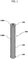
- FIG. 1 shows an example of a glued-in rod (GIR) 100 for joining wooden building components together.
- the GIR 100 may be an example of a metal joint.
- the GIR 100 may be used for building components including vertical structural members, such as posts, and horizontal structural members, such as beams and groundsills. Note that each of the horizontal and vertical structural members may be made of solid wood, laminated wood, or a combination thereof.
- the GIR 100 is made of, for example, a rolled steel for general structural applications, such as SS400, and has a small diameter portion 120 and two large diameter portions 140.
- the small diameter portion 120 has an elongated shape and a circular cross section.
- the large diameter portions 140 are fixed individually at locations spaced apart from each other in the longitudinal direction of the small diameter portion 120.
- the term "circular” refers not only to a perfect circle but also to a substantially and seemingly circular shape (the same applies to other shape-related terms herein).
- the entire length of the small diameter portion 120 is adapted such that the small diameter portion 120 can be entirely accommodated in a hole 210 extending in a building component 200 from one surface thereof in the direction perpendicular to the one surface. Furthermore, the outer diameter of the small diameter portion 120 is smaller than the inner diameter of the hole 210 such that a cylindrical gap GAP is created between the small diameter portion 120 and the inner periphery of the hole 210 when the GIR 100 is fitted into the hole 210.
- the gap GAP has dimensions that allow an adhesive such as an epoxy resin to flow therethrough in its longitudinal direction.
- the small diameter portion 120 has an internal thread 120A on a surface of one longitudinal end, more specifically, on a surface of the end to be located near the opening of the hole 210 of the building component 200.
- the internal thread 120A is adapted to receive a screwed-in bolt such as a hexagon socket head bolt or a hexagon bolt.
- the bolt may be an example of a fastener.
- the internal thread 120A extends in the longitudinal direction of the small diameter portion 120 in a center portion of the transverse cross section of the small diameter portion 120.
- the small diameter portion 120 has an external thread 120B extending in a spiral on the outer peripheral surface.
- the external thread 120B may be an example of irregularities for enhancing the adhesive bonding strength of the small diameter portion 120.
- the irregularities for enhancing the adhesive bonding strength of the small diameter portion 120 are not limited to the external thread 120B, but may be other forms formed on the outer peripheral surface of the small diameter portion 120. Other examples of such irregularities may include a plurality of thick annular rings and a plurality of protrusions and/or recesses.
- the large diameter portions 140 are coaxially fixed to the small diameter portion 120, by brazing or the like, individually at two locations spaced apart from each other in the longitudinal direction of the small diameter portion 120, preferably, at the opposite longitudinal ends of the small diameter portion 120.
- the large diameter portion 140 has an outer diameter corresponding to the inner diameter of the hole 210 of the building component 200, that is, has an outer diameter substantially equal to the inner diameter of the hole 210 so as to allow accurate positioning of the GIR 100 with respect to the hole 210 when the GIR 100 is fitted in the hole 210.
- the large diameter portions 140 function as positioning members to position the small diameter portion 120 coaxially with the hole 210 of the building component 200 when the GIR 100 is fitted in the hole 210, and thus, the GIR 100 can be positioned in the hole 210 with improved accuracy.
- each large diameter portion 140 is not limited to a thick cylindrical shape.
- the large diameter portion 140 may be a spring ring that is made of, for example, a cold rolled spring steel strip and has an outer diameter larger than the inner diameter of the hole 210 of the building component 200.
- the spring ring is elastically deformed to reduce its diameter while the GIR 100 is being fitted in the hole 210 of the building component 200, and is urged to expand its diameter by its elastic force after being fitted in the hole 210.
- the large diameter portion 140 is capable of retaining the position of the GIR 100 with respect to the hole 210.
- FIGS. 3A to 3D show an example of an embodiment of the present invention, namely a procedure for fixing the GIR 100 in one end surface of the building component 200 having an elongated shape.
- the hole 210 adapted to receive the GIR 100 fitted thereinto is formed on one longitudinal end surface of the building component 200 using a drill or the like.
- the entire length of the hole 210 may be equal to or longer than the entire length of the GIR 100 so that the GIR 100 can be entirely accommodated in the hole 210.
- an adhesive injection hole 220 and an adhesive fill check hole 230, both of which communicate with the hole 210, are formed in one side surface of the building component 200.
- the adhesive injection hole 220 and the adhesive fill check hole 230 are formed at positions that allow the holes 220, 230 communicate with the gap GAP, which is to be formed between the two large diameter portions 140 when the GIR 100 is fitted in the hole 210.
- the adhesive injection hole 220 is located near the bottom of the hole 210, and the adhesive fill check hole 230 is located near the opening of the hole 210.
- an adhesive may be input to fill an innermost portion of the hole 210 in this first step.
- the GIR 100 is fitted into the hole 210 of the building component 200 until reaching a predetermined position.
- the predetermined position may be a position that makes one surface of the upper large diameter portion 140 of the GIR 100 flush with the one end surface of the building component 200.
- the GIR 100 does not project from the one end surface of the building component 200. This ensures that when an additional building component is joined onto the one end surface of the building component 200, the GIR 100 does not interfere with the additional building component.
- the two large diameter portions 140 fixed to the opposite longitudinal ends of the small diameter portion 120 minimize the inclination of the central axis of the small diameter portion 120 with respect to the central axis of the hole 210 of the building component 200.
- an adhesive is injected from the adhesive injection hole 220.
- the adhesive injected from the adhesive injection hole 220 is supplied to the cylindrical gap GAP between the hole 210 of the building component 200 and the GIR 100 and flows toward the opening of the hole 210 having a lower flow resistance.
- the adhesive while flowing in the longitudinal direction of the gap GAP, the adhesive enters the valley of the external thread 120B formed on the outer peripheral surface of the small diameter portion 120 of the GIR 100.
- the fourth step it is checked whether the adhesive has flowed out from the adhesive fill check hole 230.
- the injection of the adhesive is continued until the adhesive flows out from the adhesive fill check hole 230, since such a state may be considered to indicate that the gap GAP has been filled up with the adhesive.
- the injection of the adhesive is stopped and the adhesive is cured until sufficiently hardened.
- the adhesive input to fill the gap GAP bonds the GIR 100 to the building component 200.
- the adhesive also fills the valley of the external thread 120B of the small diameter portion 120. This suppresses the movement of the GIR 100 in the longitudinal direction of the hole 210, and improves the fixing strength of the GIR 100 to the building component 200.
- the distance between the adhesive injection hole 220 and the small diameter portion 120 of the GIR 100 may be very small and may make it difficult to inject the adhesive into the gap GAP.
- the small diameter portion 120 may have a segment with a circumferential surface 120C having an outer diameter smaller than the outer diameter of the external thread 120B (that is, smaller than the outer diameter of the small diameter portion 120).
- the segment which is obtained by dividing the small diameter portion 120 in its longitudinal direction, extends in a predetermined length in the longitudinal direction of the small diameter portion 120 so as to face the opening of the adhesive injection hole 220. This makes it possible to increase the outer diameter of the small diameter portion 120 of the GIR 100, and thus, to use a bolt having a greater nominal diameter. Accordingly, the joining strength of the building component 200 can be improved.
- a joining portion 160 having an external thread 160A on the outer peripheral surface may be integrally coupled onto a surface of the one end of the small diameter portion 120 of the GIR 100 instead of forming the internal thread 120A thereon, as shown in FIG. 5 .
- the joining portion 160 extends in the longitudinal direction of the small diameter portion 120 in a center portion of the transverse cross section of the small diameter portion 120 and has the external thread 160A at least in a distal end section thereof.
- the entire length of the joining portion 160 may be determined according to, for example, what building components are joined together with the GIR 100.
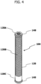
- the small diameter portion 120 of the GIR 100 may have the circumferential surface 120C as shown in FIG. 4 .
- a metal joining bracket adapted to be used in conjunction with the GIR 100 to join building components together.
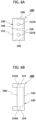
- FIGS. 6Ato 6C show an example of a metal joining bracket 300.
- the metal joining bracket 300 is made of, for example, a rolled steel for general structural applications, such as SS400, and has a channel-shaped (C-shaped) body member 320 and three rectangular reinforcing members 340 for reinforcing the body member 320.
- the body member 320 has a top plate 322, a bottom plate 324, and a side plate 326, each of which has a rectangular shape.
- the top plate 322 and bottom plate 324 are joined by welding or the like onto the opposite (upper and lower) ends of the side plate 326 so as to be parallel with each other.
- the top plate 322 has insertion holes 322A, each adapted to receive the shank of a bolt, individually at two locations spaced apart from each other in the longitudinal direction of the top plate 322.
- the bolt may be an example of the fastener.
- the bottom plate 324 has insertion holes 324A, each adapted to receive the shank of a bolt, individually at two locations spaced apart from each other in the longitudinal direction of the bottom plate 324.
- the bolt may also be an example of the fastener.
- the reinforcing members 340 are joined onto the inner surfaces of the top plate 322, bottom plate 324 and side plate 326 of the body member 320 by welding or the like so that each of the plate surfaces of the reinforcing members 340 lies in a plane orthogonal to the top plate 322, bottom plate 324 and side plate 326. More specifically, the reinforcing members 340 are joined individually at the center and opposite ends of the top plate 322, bottom plate 324 and side plate 326, in a plan view. In the example shown in FIGS. 6A to 6C , each reinforcing member 340 has a width that partially fills the corresponding cross section of the channel-shaped opening. Note, however, that each reinforcing member 340 may entirely fill this cross section of the channel-shaped opening as long as the function of the tool for fastening the fastener may be enabled.
- FIG. 7 shows an example of a beam-dominated (beam-post) structure in which a beam BM is joined onto the upper surfaces of a pair of posts PT.
- Each post PT has an upper end portion with a stepped shape. Specifically, a center area of the upper end portion projects upward so that the metal joining brackets 300 may be fitted onto the opposite side surfaces of the post PT in the longitudinal direction of the beam BM.
- four GIRs 100 are fixed onto the lower step surfaces of the stepped portion of each post PT at the locations that are to face the insertion holes 324A of the bottom plates 324 of two metal joining brackets 300.
- eight GIRs 100 are fixed onto right and left areas of the lower surface of the beam BM at the locations that are to face the insertion holes 322A of the top plates 322 of the four metal joining brackets 300.
- the beam BM is placed on the upper surfaces of the pair of posts PT, and the metal joining brackets 300 are then fitted onto the opposite side surfaces of the stepped portion of each post PT.
- fasteners each including, for example, a hexagon socket head bolt and a washer are inserted through the insertion holes 322A, 324A of the metal joining brackets 300, and screwed into the internal threads 120A of the GIRs 100.
- a member for temporarily joining the posts PT and the beam BM may be used when the beam BM is placed on the upper surfaces of the posts PT.
- the first embodiment provides improved positioning accuracy of the GIRs 100 with respect to the posts PT and beam BM, and thus, provides improved joining accuracy between the beam BM and the posts PT, such as minimizing a position gap between the beam BM and each post PT.
- the resultant complete structure may have an improved accuracy and thus, has improved quality.
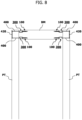
- FIG. 8 shows an example of a post-dominated (post-beam) structure in which a beam BM is joined onto side surfaces of a pair of posts PT.
- the beam BM has portions each having a stepped shape at the opposite longitudinal ends. Specifically, a center area of each of these end portions projects laterally outward so that the metal joining brackets 300 may be fitted onto the upper and lower surfaces of the beam BM.
- four GIRs 100 are fixed onto the lower step surfaces of the stepped portions of the beam BM at the locations that are to face the corresponding ones of the insertion holes 322A, 324A of two metal joining brackets 300.
- each post PT has through holes (not shown) in an upper end portion. Specifically, each of these through holes extends between opposite side surfaces of the post PT at the locations that are to face the remaining ones of the insertion holes 322A, 324A of the corresponding two metal joining brackets 300.
- the beam BM is placed between the pair of posts PT, and the metal joining brackets 300 are then fitted onto the upper and lower surfaces of the stepped portions of the beam BM.
- a fastener including, for example, a hexagon socket head bolt and a washer, is inserted through the insertion hole 322A or 324A of each metal joining bracket 300, and screwed into the internal thread 120A of the corresponding GIR 100.
- bolts 400 are inserted through the through holes of the posts PT from the surfaces, not facing the beam BM, of the posts PT so that the distal ends of the bolts 400 are inserted through the remaining ones of the insertion holes 322A, 324A of the metal joining brackets 300.
- fasteners each including, for example, a nut and a washer, are screwed onto the portions, projecting from these insertion holes 322A, 324A of the metal joining brackets 300, of the bolts 400.
- a member for temporarily joining the posts PT and the beam BM may be used when the beam BM is placed between the posts PT.
- metal plates 420 having insertion holes adapted to receive the shanks of the bolts 400 therethrough are attached onto the surfaces, not facing the beam BM, of the posts PT.
- the second embodiment provides improved positioning accuracy of the GIRs 100 with respect to the posts PT and beam BM, and thus, provides improved joining accuracy between the beam BM and the posts PT, such as minimizing a position gap between the beam BM and each post PT.
- the resultant complete structure may have an improved accuracy and thus, has improved quality.
- the GIRs 100 may be fixed in the upper end portion of each post PT.
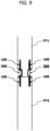
- FIG. 9 shows an example of a structure in which an upper post PT1 and a lower post PT2 are linearly joined together.
- the upper post PT1 has a lower end portion with a stepped shape. Specifically, a center area of the lower end portion projects downward so that the metal joining brackets 300 may be fitted onto the opposite side surfaces of the lower end portion.
- four GIRs 100 are fixed onto the upper step surfaces of the stepped portion of the post PT1 at the locations that are to face the insertion holes 322A of the top plates 322 of two metal joining brackets 300.
- four GIRs 100 are fixed onto the upper end surface of the lower post PT2 at the locations that are to face the insertion holes 324A of the bottom plates 324 of the two metal joining brackets 300.
- the post PT1 is placed on the post PT2 in a straight line with the lower end of the post PT1 in contact with the upper end of the post PT2, and the metal joining brackets 300 are then fitted onto the opposite side surfaces of the stepped portion of the upper post PT1.
- fasteners each including, for example, a hexagon socket head bolt and a washer are inserted through the insertion holes 322A, 324A of the metal joining brackets 300, and screwed into the internal threads 120A of the GIRs 100.
- a member for temporarily joining the posts PT1, PT2 may be used when the post PT1 is placed on the post PT2.
- the third embodiment provides improved positioning accuracy of the GIRs 100 with respect to the posts PT1, PT2, and thus, provides improved joining accuracy between the posts PT1, PT2, such as minimizing a position gap between the posts PT1, PT2.
- the resultant complete structure may have an improved accuracy and thus, has improved quality.
- application of the third embodiment is not limited to a structure in which the upper and lower posts are lineally joined together, but the third embodiment may also be applied to a structure in which two horizontal structural members, such as beams or groundsills, are lineally joined together.
- the GIRs 100 are not limited to the structures according to the first to third embodiments, but the GIRs 100 may be used in various locations of wooden buildings. Thus, when used in a wooden building, the GIRs 100 provides the resultant complete building an improved quality, such as an improved load-bearing capacity to resist external forces due to earthquakes, typhoons, and the like.
Landscapes
- Engineering & Computer Science (AREA)
- Architecture (AREA)
- Physics & Mathematics (AREA)
- Electromagnetism (AREA)
- Civil Engineering (AREA)
- Structural Engineering (AREA)
- General Engineering & Computer Science (AREA)
- Mechanical Engineering (AREA)
- Joining Of Building Structures In Genera (AREA)
Description
- The present invention relates to a metal joint for use in glued-in rod connection.
- In a timber building, high load-bearing and rigid joins are required. To satisfy such needs, glued-in rods (GIRs) as disclosed in
JP 2016-37797 A US 2016/145854 A discloses a method for connecting building members using an adhesive, a threaded rod without spring rings, wherein an adhesive discharge hole and an adhesive filling hole are arranged on separate building members. - Patent Document 1:
JP 2016-37797 A - Specifically, the GIR is fitted to the building component with a gap to be filled with an adhesive between the GIR and the hole of the building component. Such a gap undesirably permits the hole of the building component and the GIR to be displaced relative to each other by a distance depending on the gap. This deteriorates positioning accuracy of the GIR with respect to the hole of the building component. Thus, for example, using the GIR to join a vertical structural member and a horizontal structural member may cause a position gap therebetween at the join.
- Therefore, the present invention has been made to provide a metal joint providing an improved positioning accuracy with respect to a hole of a building component.
- To this end, according to the present invention, there is provided a method for fixing a metal joint adapted to be fitted into a hole formed in one end surface of a building component having an elongated shape, the metal joint comprising: a small diameter portion having an elongated shape and an outer diameter smaller than an inner diameter of the hole; and two large diameter portions fixed to the small diameter portion individually at two locations spaced apart from each other in a longitudinal direction of the small diameter portion, each large diameter portion having an outer diameter corresponding to the inner diameter of the hole, each of the large diameter portions comprising a spring ring, each spring ring having an outer diameter larger than the inner diameter of the hole, each spring ring being capable of retaining a position with respect to the hole by elastic force, wherein irregularities are formed on an outer peripheral surface of the small diameter portion in a section between the two large diameter portions; and
wherein the method comprises the steps of: forming the hole for fitting the metal joint in the one end surface of the building component, and also forming an adhesive injection hole and an adhesive fill check hole, both of which communicate with the hole for fitting the metal joint, in one side surface of the building component; fitting the metal joint into the hole formed in the building component until reaching a predetermined position; injecting an adhesive into the adhesive injection hole to supply the adhesive to a gap between the small diameter portion of the metal joint and the building component; and checking whether the adhesive has flowed out of the adhesive fill check hole, and when the adhesive has flowed out, stopping injecting the adhesive and curing the adhesive until the adhesive is sufficiently hardened. - The present invention provides improved positioning accuracy with respect to a hole of a building component.
-
-
FIG. 1 is a perspective view of an example of a GIR for joining building components together. -
FIG. 2 is a vertical cross-sectional view of the GIR fixed to a building component. -
FIG. 3A illustrates the first step of a procedure for fixing a GIR to a building component. -
FIG. 3B illustrates the second step of the procedure for fixing the GIR to the building component. -
FIG. 3C illustrates the third step of the procedure for fixing the GIR to the building component. -
FIG. 3D illustrates the fourth step of the procedure for fixing the GIR to the building component. -
FIG. 4 is a perspective view of a first modified example of the GIR for joining building components together. -
FIG. 5 is a perspective view of a second modified example of the GIR for joining building components together. -
FIG. 6A is a plan view of an example of a metal joining bracket. -
FIG. 6B is a side view of an example of the metal joining bracket. -
FIG. 6C is a front view of an example of the metal joining bracket. -
FIG. 7 is a front view of an example of a beam-dominated (beam-post) structure. -
FIG. 8 is a front view of an example of a post-dominated (post-beam) structure. -
FIG. 9 is a front view of an example of a structure in which upper and lower posts are joined together. - Embodiments for implementing the present invention will be described in detail below with reference to the accompanying drawings.
-
FIG. 1 shows an example of a glued-in rod (GIR) 100 for joining wooden building components together. Here, theGIR 100 may be an example of a metal joint. TheGIR 100 may be used for building components including vertical structural members, such as posts, and horizontal structural members, such as beams and groundsills. Note that each of the horizontal and vertical structural members may be made of solid wood, laminated wood, or a combination thereof. - The GIR 100 is made of, for example, a rolled steel for general structural applications, such as SS400, and has a
small diameter portion 120 and twolarge diameter portions 140. Thesmall diameter portion 120 has an elongated shape and a circular cross section. Thelarge diameter portions 140 are fixed individually at locations spaced apart from each other in the longitudinal direction of thesmall diameter portion 120. As used herein, the term "circular" refers not only to a perfect circle but also to a substantially and seemingly circular shape (the same applies to other shape-related terms herein). - As shown in
FIG. 2 , the entire length of thesmall diameter portion 120 is adapted such that thesmall diameter portion 120 can be entirely accommodated in ahole 210 extending in abuilding component 200 from one surface thereof in the direction perpendicular to the one surface. Furthermore, the outer diameter of thesmall diameter portion 120 is smaller than the inner diameter of thehole 210 such that a cylindrical gap GAP is created between thesmall diameter portion 120 and the inner periphery of thehole 210 when theGIR 100 is fitted into thehole 210. The gap GAP has dimensions that allow an adhesive such as an epoxy resin to flow therethrough in its longitudinal direction. Thesmall diameter portion 120 has aninternal thread 120A on a surface of one longitudinal end, more specifically, on a surface of the end to be located near the opening of thehole 210 of thebuilding component 200. Theinternal thread 120A is adapted to receive a screwed-in bolt such as a hexagon socket head bolt or a hexagon bolt. The bolt may be an example of a fastener. Theinternal thread 120A extends in the longitudinal direction of thesmall diameter portion 120 in a center portion of the transverse cross section of thesmall diameter portion 120. Also, thesmall diameter portion 120 has anexternal thread 120B extending in a spiral on the outer peripheral surface. Theexternal thread 120B may be an example of irregularities for enhancing the adhesive bonding strength of thesmall diameter portion 120. - The irregularities for enhancing the adhesive bonding strength of the
small diameter portion 120 are not limited to theexternal thread 120B, but may be other forms formed on the outer peripheral surface of thesmall diameter portion 120. Other examples of such irregularities may include a plurality of thick annular rings and a plurality of protrusions and/or recesses. - The
large diameter portions 140, each of which is thick and cylindrical, are coaxially fixed to thesmall diameter portion 120, by brazing or the like, individually at two locations spaced apart from each other in the longitudinal direction of thesmall diameter portion 120, preferably, at the opposite longitudinal ends of thesmall diameter portion 120. Thelarge diameter portion 140 has an outer diameter corresponding to the inner diameter of thehole 210 of thebuilding component 200, that is, has an outer diameter substantially equal to the inner diameter of thehole 210 so as to allow accurate positioning of theGIR 100 with respect to thehole 210 when theGIR 100 is fitted in thehole 210. Thus, thelarge diameter portions 140 function as positioning members to position thesmall diameter portion 120 coaxially with thehole 210 of thebuilding component 200 when theGIR 100 is fitted in thehole 210, and thus, theGIR 100 can be positioned in thehole 210 with improved accuracy. - Note that the shape of each
large diameter portion 140 is not limited to a thick cylindrical shape. Alternatively, for example, thelarge diameter portion 140 may be a spring ring that is made of, for example, a cold rolled spring steel strip and has an outer diameter larger than the inner diameter of thehole 210 of thebuilding component 200. In this case, the spring ring is elastically deformed to reduce its diameter while theGIR 100 is being fitted in thehole 210 of thebuilding component 200, and is urged to expand its diameter by its elastic force after being fitted in thehole 210. Thus, in this case as well, thelarge diameter portion 140 is capable of retaining the position of theGIR 100 with respect to thehole 210. -
FIGS. 3A to 3D show an example of an embodiment of the present invention, namely a procedure for fixing theGIR 100 in one end surface of thebuilding component 200 having an elongated shape. - As shown in
FIG. 3A , in the first step, thehole 210 adapted to receive theGIR 100 fitted thereinto is formed on one longitudinal end surface of thebuilding component 200 using a drill or the like. Here, the entire length of thehole 210 may be equal to or longer than the entire length of theGIR 100 so that theGIR 100 can be entirely accommodated in thehole 210. In addition, anadhesive injection hole 220 and an adhesivefill check hole 230, both of which communicate with thehole 210, are formed in one side surface of thebuilding component 200. Specifically, theadhesive injection hole 220 and the adhesivefill check hole 230 are formed at positions that allow theholes large diameter portions 140 when theGIR 100 is fitted in thehole 210. Theadhesive injection hole 220 is located near the bottom of thehole 210, and the adhesivefill check hole 230 is located near the opening of thehole 210. In some examples, an adhesive may be input to fill an innermost portion of thehole 210 in this first step. - As shown in
FIG. 3B , in the second step, theGIR 100 is fitted into thehole 210 of thebuilding component 200 until reaching a predetermined position. Here, the predetermined position may be a position that makes one surface of the upperlarge diameter portion 140 of theGIR 100 flush with the one end surface of thebuilding component 200. When theGIR 100 is at this predetermined position, theGIR 100 does not project from the one end surface of thebuilding component 200. This ensures that when an additional building component is joined onto the one end surface of thebuilding component 200, theGIR 100 does not interfere with the additional building component. Furthermore, the twolarge diameter portions 140 fixed to the opposite longitudinal ends of thesmall diameter portion 120 minimize the inclination of the central axis of thesmall diameter portion 120 with respect to the central axis of thehole 210 of thebuilding component 200. - As shown in
FIG. 3C , in the third step, an adhesive is injected from theadhesive injection hole 220. The adhesive injected from theadhesive injection hole 220 is supplied to the cylindrical gap GAP between thehole 210 of thebuilding component 200 and theGIR 100 and flows toward the opening of thehole 210 having a lower flow resistance. In this event, while flowing in the longitudinal direction of the gap GAP, the adhesive enters the valley of theexternal thread 120B formed on the outer peripheral surface of thesmall diameter portion 120 of theGIR 100. - As shown in
FIG. 3D , in the fourth step, it is checked whether the adhesive has flowed out from the adhesivefill check hole 230. The injection of the adhesive is continued until the adhesive flows out from the adhesivefill check hole 230, since such a state may be considered to indicate that the gap GAP has been filled up with the adhesive. When it is confirmed that the adhesive has flowed out from the adhesivefill check hole 230, the injection of the adhesive is stopped and the adhesive is cured until sufficiently hardened. - The adhesive input to fill the gap GAP bonds the
GIR 100 to thebuilding component 200. Here, the adhesive also fills the valley of theexternal thread 120B of thesmall diameter portion 120. This suppresses the movement of theGIR 100 in the longitudinal direction of thehole 210, and improves the fixing strength of theGIR 100 to thebuilding component 200. - In some cases, the distance between the
adhesive injection hole 220 and thesmall diameter portion 120 of theGIR 100 may be very small and may make it difficult to inject the adhesive into the gap GAP. In such a case, as shown inFIG. 4 , thesmall diameter portion 120 may have a segment with acircumferential surface 120C having an outer diameter smaller than the outer diameter of theexternal thread 120B (that is, smaller than the outer diameter of the small diameter portion 120). Specifically, the segment, which is obtained by dividing thesmall diameter portion 120 in its longitudinal direction, extends in a predetermined length in the longitudinal direction of thesmall diameter portion 120 so as to face the opening of theadhesive injection hole 220. This makes it possible to increase the outer diameter of thesmall diameter portion 120 of theGIR 100, and thus, to use a bolt having a greater nominal diameter. Accordingly, the joining strength of thebuilding component 200 can be improved. - When a nut is used as a fastener, a joining
portion 160 having anexternal thread 160A on the outer peripheral surface may be integrally coupled onto a surface of the one end of thesmall diameter portion 120 of theGIR 100 instead of forming theinternal thread 120A thereon, as shown inFIG. 5 . Specifically, the joiningportion 160 extends in the longitudinal direction of thesmall diameter portion 120 in a center portion of the transverse cross section of thesmall diameter portion 120 and has theexternal thread 160A at least in a distal end section thereof. The entire length of the joiningportion 160 may be determined according to, for example, what building components are joined together with theGIR 100. In this configuration as well, thesmall diameter portion 120 of theGIR 100 may have thecircumferential surface 120C as shown inFIG. 4 . - Next, a metal joining bracket adapted to be used in conjunction with the
GIR 100 to join building components together. -
FIGS. 6Ato 6C show an example of ametal joining bracket 300. - The
metal joining bracket 300 is made of, for example, a rolled steel for general structural applications, such as SS400, and has a channel-shaped (C-shaped)body member 320 and three rectangular reinforcingmembers 340 for reinforcing thebody member 320. - The
body member 320 has atop plate 322, abottom plate 324, and aside plate 326, each of which has a rectangular shape. Thetop plate 322 andbottom plate 324 are joined by welding or the like onto the opposite (upper and lower) ends of theside plate 326 so as to be parallel with each other. Thetop plate 322 hasinsertion holes 322A, each adapted to receive the shank of a bolt, individually at two locations spaced apart from each other in the longitudinal direction of thetop plate 322. The bolt may be an example of the fastener. Similarly, thebottom plate 324 hasinsertion holes 324A, each adapted to receive the shank of a bolt, individually at two locations spaced apart from each other in the longitudinal direction of thebottom plate 324. The bolt may also be an example of the fastener. - The reinforcing
members 340 are joined onto the inner surfaces of thetop plate 322,bottom plate 324 andside plate 326 of thebody member 320 by welding or the like so that each of the plate surfaces of the reinforcingmembers 340 lies in a plane orthogonal to thetop plate 322,bottom plate 324 andside plate 326. More specifically, the reinforcingmembers 340 are joined individually at the center and opposite ends of thetop plate 322,bottom plate 324 andside plate 326, in a plan view. In the example shown inFIGS. 6A to 6C , each reinforcingmember 340 has a width that partially fills the corresponding cross section of the channel-shaped opening. Note, however, that each reinforcingmember 340 may entirely fill this cross section of the channel-shaped opening as long as the function of the tool for fastening the fastener may be enabled. - Next, description will be given of a structure built by using the
GIRs 100 andmetal joining brackets 300 to join posts and a beam which are examples of building components. -
FIG. 7 shows an example of a beam-dominated (beam-post) structure in which a beam BM is joined onto the upper surfaces of a pair of posts PT. - Each post PT has an upper end portion with a stepped shape. Specifically, a center area of the upper end portion projects upward so that the
metal joining brackets 300 may be fitted onto the opposite side surfaces of the post PT in the longitudinal direction of the beam BM. In addition, by the aforementioned fixing method, fourGIRs 100 are fixed onto the lower step surfaces of the stepped portion of each post PT at the locations that are to face theinsertion holes 324A of thebottom plates 324 of twometal joining brackets 300. Similarly, by the aforementioned fixing method, eightGIRs 100 are fixed onto right and left areas of the lower surface of the beam BM at the locations that are to face theinsertion holes 322A of thetop plates 322 of the fourmetal joining brackets 300. - In the building process, the beam BM is placed on the upper surfaces of the pair of posts PT, and the
metal joining brackets 300 are then fitted onto the opposite side surfaces of the stepped portion of each post PT. After that, fasteners, each including, for example, a hexagon socket head bolt and a washer are inserted through the insertion holes 322A, 324A of themetal joining brackets 300, and screwed into theinternal threads 120A of theGIRs 100. In some examples, a member for temporarily joining the posts PT and the beam BM may be used when the beam BM is placed on the upper surfaces of the posts PT. - In this way, the first embodiment provides improved positioning accuracy of the
GIRs 100 with respect to the posts PT and beam BM, and thus, provides improved joining accuracy between the beam BM and the posts PT, such as minimizing a position gap between the beam BM and each post PT. As a result, the resultant complete structure may have an improved accuracy and thus, has improved quality. -
FIG. 8 shows an example of a post-dominated (post-beam) structure in which a beam BM is joined onto side surfaces of a pair of posts PT. - The beam BM has portions each having a stepped shape at the opposite longitudinal ends. Specifically, a center area of each of these end portions projects laterally outward so that the
metal joining brackets 300 may be fitted onto the upper and lower surfaces of the beam BM. In addition, by the aforementioned fixing method, fourGIRs 100 are fixed onto the lower step surfaces of the stepped portions of the beam BM at the locations that are to face the corresponding ones of the insertion holes 322A, 324A of twometal joining brackets 300. Furthermore, each post PT has through holes (not shown) in an upper end portion. Specifically, each of these through holes extends between opposite side surfaces of the post PT at the locations that are to face the remaining ones of the insertion holes 322A, 324A of the corresponding twometal joining brackets 300. - In the building process, the beam BM is placed between the pair of posts PT, and the
metal joining brackets 300 are then fitted onto the upper and lower surfaces of the stepped portions of the beam BM. After that, a fastener including, for example, a hexagon socket head bolt and a washer, is inserted through theinsertion hole metal joining bracket 300, and screwed into theinternal thread 120A of thecorresponding GIR 100. In addition,bolts 400 are inserted through the through holes of the posts PT from the surfaces, not facing the beam BM, of the posts PT so that the distal ends of thebolts 400 are inserted through the remaining ones of the insertion holes 322A, 324A of themetal joining brackets 300. Then, fasteners each including, for example, a nut and a washer, are screwed onto the portions, projecting from theseinsertion holes metal joining brackets 300, of thebolts 400. In some examples, a member for temporarily joining the posts PT and the beam BM may be used when the beam BM is placed between the posts PT. Although not mentioned above, to suppress digging of the heads of thebolts 400 into the posts PT,metal plates 420 having insertion holes adapted to receive the shanks of thebolts 400 therethrough are attached onto the surfaces, not facing the beam BM, of the posts PT. - In this way, as with the first embodiment, the second embodiment provides improved positioning accuracy of the
GIRs 100 with respect to the posts PT and beam BM, and thus, provides improved joining accuracy between the beam BM and the posts PT, such as minimizing a position gap between the beam BM and each post PT. As a result, the resultant complete structure may have an improved accuracy and thus, has improved quality. Note that, in place of the insertion holes adapted to receive thebolts 400 therethrough, theGIRs 100 may be fixed in the upper end portion of each post PT. -
FIG. 9 shows an example of a structure in which an upper post PT1 and a lower post PT2 are linearly joined together. - The upper post PT1 has a lower end portion with a stepped shape. Specifically, a center area of the lower end portion projects downward so that the
metal joining brackets 300 may be fitted onto the opposite side surfaces of the lower end portion. In addition, by the aforementioned fixing method, fourGIRs 100 are fixed onto the upper step surfaces of the stepped portion of the post PT1 at the locations that are to face theinsertion holes 322A of thetop plates 322 of twometal joining brackets 300. Similarly, by the aforementioned fixing method, fourGIRs 100 are fixed onto the upper end surface of the lower post PT2 at the locations that are to face theinsertion holes 324A of thebottom plates 324 of the twometal joining brackets 300. - In the building process, the post PT1 is placed on the post PT2 in a straight line with the lower end of the post PT1 in contact with the upper end of the post PT2, and the
metal joining brackets 300 are then fitted onto the opposite side surfaces of the stepped portion of the upper post PT1. After that, fasteners, each including, for example, a hexagon socket head bolt and a washer are inserted through the insertion holes 322A, 324A of themetal joining brackets 300, and screwed into theinternal threads 120A of theGIRs 100. In some examples, a member for temporarily joining the posts PT1, PT2 may be used when the post PT1 is placed on the post PT2. - In this way, the third embodiment provides improved positioning accuracy of the
GIRs 100 with respect to the posts PT1, PT2, and thus, provides improved joining accuracy between the posts PT1, PT2, such as minimizing a position gap between the posts PT1, PT2. As a result, the resultant complete structure may have an improved accuracy and thus, has improved quality. Note that application of the third embodiment is not limited to a structure in which the upper and lower posts are lineally joined together, but the third embodiment may also be applied to a structure in which two horizontal structural members, such as beams or groundsills, are lineally joined together. - Furthermore, application of the
GIRs 100 is not limited to the structures according to the first to third embodiments, but theGIRs 100 may be used in various locations of wooden buildings. Thus, when used in a wooden building, theGIRs 100 provides the resultant complete building an improved quality, such as an improved load-bearing capacity to resist external forces due to earthquakes, typhoons, and the like. -
- 100
- GIR (Metal joint)
- 120
- Small diameter portion
- 120A
- Internal thread
- 120B
- External thread (Irregularities)
- 120C
- Circumferential surface
- 140
- Large diameter portion
- 160
- Joining portion
- 160A
- External thread
- 200
- Building component
- 210
- Hole
- PT, PT1, PT2
- Post
- BM
- Beam
Claims (9)
- A method for fixing a metal joint (100) adapted to be fitted into a hole (210) formed in one end surface of a building component (200) having an elongated shape, the metal joint (100) comprising:a small diameter portion (120) having an elongated shape and an outer diameter smaller than an inner diameter of the hole (210); andtwo large diameter portions (140) fixed to the small diameter portion (120) individually at two locations spaced apart from each other in a longitudinal direction of the small diameter portion (120), each large diameter portion (140) having an outer diameter corresponding to the inner diameter of the hole (210), each of the large diameter portions (140) comprising a spring ring, each spring ring having an outer diameter larger than the inner diameter of the hole (210), each spring ring being capable of retaining a position with respect to the hole by elastic force,wherein irregularities (120B) are formed on an outer peripheral surface of the small diameter portion (120) in a section between the two large diameter portions (140); andwherein the method comprises the steps of:forming the hole (210) for fitting the metal joint (100) in the one end surface of the building component (200), and also forming an adhesive injection hole (220) and an adhesive fill check hole (230), both of which communicate with the hole (210) for fitting the metal joint (100), in one side surface of the building component (200);fitting the metal joint (100) into the hole (210) formed in the building component (200) until reaching a predetermined position;injecting an adhesive into the adhesive injection hole (220) to supply the adhesive to a gap (GAP) between the small diameter portion (120) of the metal joint (100) and the building component (200); andchecking whether the adhesive has flowed out of the adhesive fill check hole (230), and when the adhesive has flowed out, stopping injecting the adhesive and curing the adhesive until the adhesive is sufficiently hardened.
- The method for fixing a metal joint (100) according to claim 1, wherein the large diameter portions (140) are fixed at opposite longitudinal ends of the small diameter portion (120).
- The method for fixing a metal joint (100) according to claim 1, wherein the irregularities (120B) comprise an external thread (160A).
- The method for fixing a metal joint (100) according to claim 1, wherein the irregularities (120B) comprise a plurality of annular rings.
- The method for fixing a metal joint (100) according to claim 1, wherein the irregularities (120B) comprise a plurality of protrusions and/or recesses.
- The method for fixing a metal joint (100) according to claim 1, wherein the small diameter portion (120) has a segment with a circumferential surface having an outer diameter smaller than the outer diameter of the small diameter portion (120), the segment being obtained by dividing the section of the small diameter portion (120) between the two large diameter portions (140) in the longitudinal direction of the small diameter portion (120).
- The method for fixing a metal joint (100) according to claim 1, wherein an internal thread (120A) is formed on a surface of one longitudinal end of the small diameter portion (120).
- The method for fixing a metal joint (100) according to claim 1, wherein a joining portion (160) having an external thread (160A) in at least a distal end section thereof is coupled onto a surface of one longitudinal end of the small diameter portion (120).
- The method for fixing a metal joint (100) according to claim 8, wherein the joining portion (160) is integrally coupled to the small diameter portion (120).
Applications Claiming Priority (2)
| Application Number | Priority Date | Filing Date | Title |
|---|---|---|---|
| JP2016204720A JP6275798B1 (en) | 2016-10-18 | 2016-10-18 | Bonded hardware |
| PCT/JP2017/037594 WO2018074489A1 (en) | 2016-10-18 | 2017-10-17 | Joint fitting |
Publications (3)
| Publication Number | Publication Date |
|---|---|
| EP3530828A1 EP3530828A1 (en) | 2019-08-28 |
| EP3530828A4 EP3530828A4 (en) | 2020-06-03 |
| EP3530828B1 true EP3530828B1 (en) | 2024-02-21 |
Family
ID=61158399
Family Applications (1)
| Application Number | Title | Priority Date | Filing Date |
|---|---|---|---|
| EP17862674.3A Active EP3530828B1 (en) | 2016-10-18 | 2017-10-17 | Joint fitting |
Country Status (10)
| Country | Link |
|---|---|
| US (1) | US11352778B2 (en) |
| EP (1) | EP3530828B1 (en) |
| JP (1) | JP6275798B1 (en) |
| KR (1) | KR102374875B1 (en) |
| CN (1) | CN109844234B (en) |
| AU (1) | AU2017346916B2 (en) |
| CA (1) | CA3040639A1 (en) |
| NZ (1) | NZ752851A (en) |
| TW (1) | TWI763724B (en) |
| WO (1) | WO2018074489A1 (en) |
Families Citing this family (5)
| Publication number | Priority date | Publication date | Assignee | Title |
|---|---|---|---|---|
| US10767684B1 (en) * | 2019-04-26 | 2020-09-08 | Solsera, Inc. | Flat roof mounting device |
| US10907342B1 (en) * | 2020-02-07 | 2021-02-02 | Assembly OSM, Inc. | Connection node for modular building structures |
| EP4043737A1 (en) | 2021-02-10 | 2022-08-17 | B/E Aerospace, Inc. | Bonding concentric elements |
| WO2022212861A1 (en) * | 2021-04-01 | 2022-10-06 | Simpson Strong-Tie Company, Inc. | System for filling voids in glued-in-rod structures |
| CN115354758A (en) * | 2022-09-23 | 2022-11-18 | 南通砼星建筑科技有限公司 | Prefabricated part connecting piece and connecting mode thereof |
Citations (1)
| Publication number | Priority date | Publication date | Assignee | Title |
|---|---|---|---|---|
| US20160145854A1 (en) * | 2014-11-24 | 2016-05-26 | Scrimtec Japan Inc. Co., Ltd. | Joining structure |
Family Cites Families (55)
| Publication number | Priority date | Publication date | Assignee | Title |
|---|---|---|---|---|
| US36014A (en) * | 1862-07-29 | Improvement in bolts | ||
| US1243818A (en) * | 1917-03-20 | 1917-10-23 | Burns & Bassick Company | Method of producing hollow set-screws. |
| US2398984A (en) * | 1944-05-03 | 1946-04-23 | Floyd D Welch | Secret fastener |
| FR1434225A (en) * | 1965-01-25 | 1966-04-08 | Method and device for sealing support, in particular for roofs and mine faces | |
| DE7024434U (en) * | 1970-06-30 | 1971-02-11 | Mueller P | Wall anchors with automatic filling and adhesive extrusion in predefined zones |
| DE2745438A1 (en) * | 1977-10-08 | 1979-04-12 | Fischer Artur Dr H C | ANCHORING A FASTENING ELEMENT |
| DE3009312A1 (en) * | 1980-03-11 | 1981-09-24 | Hilti AG, 9494 Schaan | SELF DRILLING DOWEL |
| FI60278C (en) * | 1980-10-20 | 1985-07-22 | Rakennusruuvi Oy | FAESTDON |
| GB8323143D0 (en) * | 1983-08-27 | 1983-09-28 | Oxley R F | Tuning screw |
| US5145361A (en) * | 1984-12-04 | 1992-09-08 | Combustion Research, Inc. | Burner and method for metallurgical heating and melting |
| AT385306B (en) * | 1986-06-16 | 1988-03-25 | Pointner Ferdinand | ANCHOR |
| DE3641502A1 (en) * | 1986-12-04 | 1988-06-16 | Hilti Ag | Fastening element with anchor rod and shaped body |
| US5145301A (en) | 1991-02-13 | 1992-09-08 | Akio Yamamoto | Nail sustainer |
| US5230191A (en) * | 1991-05-28 | 1993-07-27 | Paul Mayrand | Precast insulated concrete panel for prefabricated building structure |
| KR950008328B1 (en) * | 1991-08-14 | 1995-07-27 | 야마모도 노부꼬 | Screwed nail sustainer |
| US6151856A (en) * | 1996-04-04 | 2000-11-28 | Shimonohara; Takeshige | Panels for construction and a method of jointing the same |
| JPH10311110A (en) * | 1997-05-13 | 1998-11-24 | Sugimoto Kenchiku Kenkyusho:Kk | Jointing structure for building |
| JP3635520B2 (en) | 1998-11-30 | 2005-04-06 | 秀利 大川 | Wood joint and method of joining wood using the joint |
| DE19955684A1 (en) * | 1999-11-19 | 2001-05-23 | Hilti Ag | Anchor rod for anchoring with organic and / or inorganic mortar compounds |
| JP2001214540A (en) | 2000-02-04 | 2001-08-10 | Sunstar Eng Inc | Wool dowel joining structure |
| DE10129441A1 (en) * | 2001-06-19 | 2003-01-02 | Fischer Artur Werke Gmbh | Xings |
| US6902366B2 (en) * | 2001-08-15 | 2005-06-07 | Ducker, Iii Andrew L. | Sealable fastener with circumferential sealant channel and sealant delivery groove for delivering sealant into the circumferential sealant channel |
| US20040109738A1 (en) * | 2001-08-15 | 2004-06-10 | Ducker Andrew L. | Sealable fastener with sealant delivery passageway to circumferential sealant channel and method |
| CN100434603C (en) * | 2002-08-06 | 2008-11-19 | 杨洪 | Building insulating vibration -isolating system |
| US7823356B2 (en) * | 2004-08-18 | 2010-11-02 | Taisei Corporation | Shearing force reinforced structure and member |
| US7827759B1 (en) * | 2007-01-04 | 2010-11-09 | Audrey Barnes | Method of repairing concrete floors and system for same |
| US8398690B2 (en) * | 2007-02-07 | 2013-03-19 | Apex Biomedical Company, Llc | Rotationally asymmetric bone screw |
| US7802953B2 (en) * | 2007-03-16 | 2010-09-28 | Robert Stephen | Inset panel fastener |
| DE102007021132B4 (en) * | 2007-05-03 | 2009-01-29 | Gs Anlagen Und Immobilien Gmbh | Stuffed mother, especially welding nut |
| US20100318130A1 (en) * | 2007-12-15 | 2010-12-16 | Parlato Brian D | Flexible rod assembly for spinal fixation |
| US20130008096A1 (en) * | 2010-04-01 | 2013-01-10 | Michael Griffiths | Utility pole |
| JP5718650B2 (en) | 2011-01-05 | 2015-05-13 | 株式会社サカワ | Joining method of wooden frames |
| US20120180423A1 (en) * | 2011-01-19 | 2012-07-19 | Seismic Design Toolbox, Inc. | Yielding Rod to Counter Seismic Activity |
| DE102011012955A1 (en) * | 2011-03-08 | 2012-09-13 | Karlsruher Institut für Technologie | Anchor fastener |
| DE102011005999A1 (en) * | 2011-03-23 | 2012-09-27 | Hilti Aktiengesellschaft | expansion anchor |
| CN102858116A (en) * | 2011-06-29 | 2013-01-02 | 深圳富泰宏精密工业有限公司 | Electronic device, nut screw thereof and assembly method of electronic device |
| JP5957257B2 (en) * | 2012-03-27 | 2016-07-27 | 住友林業株式会社 | Wood member joint structure |
| BE1020597A3 (en) * | 2012-03-30 | 2014-01-07 | Vandenbempt Patent | QUICK-BUILT STONE, AS WELL AS PLASTIC INSERT FOR MANUFACTURING SUCH QUICK-BUILDING STONE. |
| DE202012005380U1 (en) * | 2012-06-01 | 2013-09-03 | Interroll-Holding Ag | Motorized conveyor roller for conveyor systems for conveying containers, pallets and the like |
| JP6001367B2 (en) * | 2012-07-26 | 2016-10-05 | 株式会社駒井ハルテック | Anchor bolt positioning tool |
| CH706824B1 (en) * | 2012-08-14 | 2016-10-14 | S & P Clever Reinforcement Company Ag | Anchoring system for a support structure in construction, as well as methods for attaching and pretensioning an anchor rod. |
| DE102012215587A1 (en) * | 2012-09-03 | 2014-06-12 | Leichtbau-Zentrum Sachsen Gmbh | Load introduction element for flat or curved plastic or fiber composite element, has force transmission element with contour designed as cycloid corrugation and including axial sequence of opposing notches |
| DE102013204704B4 (en) * | 2013-03-18 | 2015-02-26 | Confitt Gmbh | Tool-free attachable mounting element |
| US9127705B2 (en) * | 2013-11-29 | 2015-09-08 | Gregory Robert Silas | Concrete masonry anchor and method of fastening |
| CN104684308A (en) * | 2013-11-29 | 2015-06-03 | 英业达科技有限公司 | Plastic panel |
| US9200661B2 (en) * | 2013-12-19 | 2015-12-01 | GM Global Technology Operations LLC | Flow drill screw |
| DE102014205448A1 (en) * | 2014-03-24 | 2015-09-24 | Mahle International Gmbh | sleeve insert |
| JP5566553B1 (en) * | 2014-04-23 | 2014-08-06 | 旭産商株式会社 | Anchor member and its construction method |
| JP2016037797A (en) | 2014-08-08 | 2016-03-22 | 清水建設株式会社 | Column-beam joining structure |
| WO2016090018A1 (en) * | 2014-12-02 | 2016-06-09 | Akp Consulting | Active compression devices, methods of assembly and methods of use |
| US10053863B2 (en) * | 2015-06-05 | 2018-08-21 | Eric Fenske | Multi-purpose anchor devices |
| US10443230B2 (en) * | 2016-02-10 | 2019-10-15 | Black & Decker, Inc. | Composite deck fastener |
| CN106436748A (en) * | 2016-07-04 | 2017-02-22 | 中国电建集团华东勘测设计研究院有限公司 | Rock anchor foundation structure applicable to mountain photovoltaic assembly and construction method thereof |
| CN106320564A (en) * | 2016-09-06 | 2017-01-11 | 沈阳远大瑞福工程技术有限公司 | Alignment connector of concave-box wallboard |
| GB2563452A (en) * | 2017-06-16 | 2018-12-19 | Www Opennshut Co Uk Ltd | Fixing device |
-
2016
- 2016-10-18 JP JP2016204720A patent/JP6275798B1/en active Active
-
2017
- 2017-10-16 TW TW106135361A patent/TWI763724B/en active
- 2017-10-17 KR KR1020197009793A patent/KR102374875B1/en active IP Right Grant
- 2017-10-17 NZ NZ752851A patent/NZ752851A/en unknown
- 2017-10-17 CN CN201780058301.1A patent/CN109844234B/en active Active
- 2017-10-17 EP EP17862674.3A patent/EP3530828B1/en active Active
- 2017-10-17 WO PCT/JP2017/037594 patent/WO2018074489A1/en unknown
- 2017-10-17 AU AU2017346916A patent/AU2017346916B2/en active Active
- 2017-10-17 CA CA3040639A patent/CA3040639A1/en active Pending
- 2017-10-17 US US16/342,790 patent/US11352778B2/en active Active
Patent Citations (1)
| Publication number | Priority date | Publication date | Assignee | Title |
|---|---|---|---|---|
| US20160145854A1 (en) * | 2014-11-24 | 2016-05-26 | Scrimtec Japan Inc. Co., Ltd. | Joining structure |
Also Published As
| Publication number | Publication date |
|---|---|
| WO2018074489A1 (en) | 2018-04-26 |
| AU2017346916A1 (en) | 2019-05-02 |
| KR102374875B1 (en) | 2022-03-16 |
| US20200056368A1 (en) | 2020-02-20 |
| JP6275798B1 (en) | 2018-02-07 |
| US11352778B2 (en) | 2022-06-07 |
| KR20190066013A (en) | 2019-06-12 |
| AU2017346916B2 (en) | 2022-11-24 |
| JP2018066163A (en) | 2018-04-26 |
| CN109844234B (en) | 2021-06-29 |
| CN109844234A (en) | 2019-06-04 |
| EP3530828A1 (en) | 2019-08-28 |
| NZ752851A (en) | 2021-12-24 |
| TW201825749A (en) | 2018-07-16 |
| EP3530828A4 (en) | 2020-06-03 |
| TWI763724B (en) | 2022-05-11 |
| CA3040639A1 (en) | 2018-04-26 |
Similar Documents
| Publication | Publication Date | Title |
|---|---|---|
| EP3530828B1 (en) | Joint fitting | |
| WO2015182714A1 (en) | Structure and method for joining column and beam | |
| US20170268224A1 (en) | Inter-element joint structure | |
| JP2018145786A (en) | Pipe body connection structure and unit building | |
| ITFI940164A1 (en) | SUPPORTING METALLIC STRUCTURE WITH STRUCTURAL KNOTS FREE FROM WELDING AND DRILLING | |
| KR100919701B1 (en) | Beam-column connection of precast members | |
| JP6248361B2 (en) | Friction damper and wall body | |
| JP2016132868A (en) | Bar-form metal fitting | |
| JP2011153437A (en) | Reinforcing hardware | |
| JP6351471B2 (en) | Connected structure | |
| KR101433065B1 (en) | Prefabricated Steel frame for composite member of steel and concrete | |
| KR101739081B1 (en) | Buckling Restraint Brace with assembly type precast concrete restraint material | |
| JP2000248776A (en) | Quake control mechanism and wall body using it | |
| JP6894215B2 (en) | Steel composite member and its manufacturing method | |
| JP2007077612A (en) | Column base part joint structure of wooden column, and its column base part joint implement | |
| WO2021014616A1 (en) | Steel reinforced joint, steel reinforced assembly, and precast steel reinforced concrete body | |
| CN111021342A (en) | Quick butt joint subassembly and quick butt joint mechanism | |
| JP2017133186A (en) | Installing structure of steel land covering part | |
| JP6921413B2 (en) | Reinforcing bar joints and rebar assemblies, as well as precast reinforced concrete bodies | |
| JP4062278B2 (en) | Beam-column joint structure | |
| TWI604113B (en) | The brace element with the pre-linked gusset plates. | |
| CN212452610U (en) | Quick butt joint subassembly and quick butt joint mechanism | |
| GB2569186A (en) | Method for the reinforcement of masonry structures | |
| JP2001336303A (en) | Vibration control mechanism and wall body using it | |
| JP6174377B2 (en) | Segment connection structure |
Legal Events
| Date | Code | Title | Description |
|---|---|---|---|
| STAA | Information on the status of an ep patent application or granted ep patent |
Free format text: STATUS: THE INTERNATIONAL PUBLICATION HAS BEEN MADE |
|
| PUAI | Public reference made under article 153(3) epc to a published international application that has entered the european phase |
Free format text: ORIGINAL CODE: 0009012 |
|
| STAA | Information on the status of an ep patent application or granted ep patent |
Free format text: STATUS: REQUEST FOR EXAMINATION WAS MADE |
|
| 17P | Request for examination filed |
Effective date: 20190508 |
|
| AK | Designated contracting states |
Kind code of ref document: A1 Designated state(s): AL AT BE BG CH CY CZ DE DK EE ES FI FR GB GR HR HU IE IS IT LI LT LU LV MC MK MT NL NO PL PT RO RS SE SI SK SM TR |
|
| AX | Request for extension of the european patent |
Extension state: BA ME |
|
| DAV | Request for validation of the european patent (deleted) | ||
| DAX | Request for extension of the european patent (deleted) | ||
| A4 | Supplementary search report drawn up and despatched |
Effective date: 20200430 |
|
| RIC1 | Information provided on ipc code assigned before grant |
Ipc: F16B 35/00 20060101ALN20200424BHEP Ipc: F16B 11/00 20060101ALN20200424BHEP Ipc: E04B 1/26 20060101AFI20200424BHEP Ipc: F16B 13/14 20060101ALI20200424BHEP Ipc: F16B 37/04 20060101ALI20200424BHEP Ipc: E04B 1/58 20060101ALI20200424BHEP Ipc: F16B 37/12 20060101ALN20200424BHEP |
|
| STAA | Information on the status of an ep patent application or granted ep patent |
Free format text: STATUS: EXAMINATION IS IN PROGRESS |
|
| 17Q | First examination report despatched |
Effective date: 20220325 |
|
| RIC1 | Information provided on ipc code assigned before grant |
Ipc: F16B 37/12 20060101ALN20230809BHEP Ipc: F16B 35/00 20060101ALN20230809BHEP Ipc: F16B 11/00 20060101ALN20230809BHEP Ipc: F16B 37/04 20060101ALI20230809BHEP Ipc: F16B 13/14 20060101ALI20230809BHEP Ipc: E04B 1/58 20060101ALI20230809BHEP Ipc: E04B 1/26 20060101AFI20230809BHEP |
|
| RIC1 | Information provided on ipc code assigned before grant |
Ipc: F16B 37/12 20060101ALN20230831BHEP Ipc: F16B 35/00 20060101ALN20230831BHEP Ipc: F16B 11/00 20060101ALN20230831BHEP Ipc: F16B 37/04 20060101ALI20230831BHEP Ipc: F16B 13/14 20060101ALI20230831BHEP Ipc: E04B 1/58 20060101ALI20230831BHEP Ipc: E04B 1/26 20060101AFI20230831BHEP |
|
| GRAP | Despatch of communication of intention to grant a patent |
Free format text: ORIGINAL CODE: EPIDOSNIGR1 |
|
| STAA | Information on the status of an ep patent application or granted ep patent |
Free format text: STATUS: GRANT OF PATENT IS INTENDED |
|
| INTG | Intention to grant announced |
Effective date: 20231017 |
|
| GRAS | Grant fee paid |
Free format text: ORIGINAL CODE: EPIDOSNIGR3 |
|
| GRAA | (expected) grant |
Free format text: ORIGINAL CODE: 0009210 |
|
| STAA | Information on the status of an ep patent application or granted ep patent |
Free format text: STATUS: THE PATENT HAS BEEN GRANTED |
|
| AK | Designated contracting states |
Kind code of ref document: B1 Designated state(s): AL AT BE BG CH CY CZ DE DK EE ES FI FR GB GR HR HU IE IS IT LI LT LU LV MC MK MT NL NO PL PT RO RS SE SI SK SM TR |
|
| REG | Reference to a national code |
Ref country code: GB Ref legal event code: FG4D |
|
| REG | Reference to a national code |
Ref country code: CH Ref legal event code: EP |
|
| REG | Reference to a national code |
Ref country code: IE Ref legal event code: FG4D |
|
| REG | Reference to a national code |
Ref country code: DE Ref legal event code: R096 Ref document number: 602017079417 Country of ref document: DE |
|
| U01 | Request for unitary effect filed |
Effective date: 20240221 |
|
| U07 | Unitary effect registered |
Designated state(s): AT BE BG DE DK EE FI FR IT LT LU LV MT NL PT SE SI Effective date: 20240227 |
|
| REG | Reference to a national code |
Ref country code: LT Ref legal event code: MG9D |
|
| PG25 | Lapsed in a contracting state [announced via postgrant information from national office to epo] |
Ref country code: IS Free format text: LAPSE BECAUSE OF FAILURE TO SUBMIT A TRANSLATION OF THE DESCRIPTION OR TO PAY THE FEE WITHIN THE PRESCRIBED TIME-LIMIT Effective date: 20240621 |
|
| PG25 | Lapsed in a contracting state [announced via postgrant information from national office to epo] |
Ref country code: GR Free format text: LAPSE BECAUSE OF FAILURE TO SUBMIT A TRANSLATION OF THE DESCRIPTION OR TO PAY THE FEE WITHIN THE PRESCRIBED TIME-LIMIT Effective date: 20240522 |
|
| PG25 | Lapsed in a contracting state [announced via postgrant information from national office to epo] |
Ref country code: RS Free format text: LAPSE BECAUSE OF FAILURE TO SUBMIT A TRANSLATION OF THE DESCRIPTION OR TO PAY THE FEE WITHIN THE PRESCRIBED TIME-LIMIT Effective date: 20240521 Ref country code: HR Free format text: LAPSE BECAUSE OF FAILURE TO SUBMIT A TRANSLATION OF THE DESCRIPTION OR TO PAY THE FEE WITHIN THE PRESCRIBED TIME-LIMIT Effective date: 20240221 |
|
| PG25 | Lapsed in a contracting state [announced via postgrant information from national office to epo] |
Ref country code: ES Free format text: LAPSE BECAUSE OF FAILURE TO SUBMIT A TRANSLATION OF THE DESCRIPTION OR TO PAY THE FEE WITHIN THE PRESCRIBED TIME-LIMIT Effective date: 20240221 |
|
| PG25 | Lapsed in a contracting state [announced via postgrant information from national office to epo] |
Ref country code: RS Free format text: LAPSE BECAUSE OF FAILURE TO SUBMIT A TRANSLATION OF THE DESCRIPTION OR TO PAY THE FEE WITHIN THE PRESCRIBED TIME-LIMIT Effective date: 20240521 Ref country code: IS Free format text: LAPSE BECAUSE OF FAILURE TO SUBMIT A TRANSLATION OF THE DESCRIPTION OR TO PAY THE FEE WITHIN THE PRESCRIBED TIME-LIMIT Effective date: 20240621 Ref country code: HR Free format text: LAPSE BECAUSE OF FAILURE TO SUBMIT A TRANSLATION OF THE DESCRIPTION OR TO PAY THE FEE WITHIN THE PRESCRIBED TIME-LIMIT Effective date: 20240221 Ref country code: GR Free format text: LAPSE BECAUSE OF FAILURE TO SUBMIT A TRANSLATION OF THE DESCRIPTION OR TO PAY THE FEE WITHIN THE PRESCRIBED TIME-LIMIT Effective date: 20240522 Ref country code: ES Free format text: LAPSE BECAUSE OF FAILURE TO SUBMIT A TRANSLATION OF THE DESCRIPTION OR TO PAY THE FEE WITHIN THE PRESCRIBED TIME-LIMIT Effective date: 20240221 |
|
| PG25 | Lapsed in a contracting state [announced via postgrant information from national office to epo] |
Ref country code: PL Free format text: LAPSE BECAUSE OF FAILURE TO SUBMIT A TRANSLATION OF THE DESCRIPTION OR TO PAY THE FEE WITHIN THE PRESCRIBED TIME-LIMIT Effective date: 20240221 |
|
| PG25 | Lapsed in a contracting state [announced via postgrant information from national office to epo] |
Ref country code: PL Free format text: LAPSE BECAUSE OF FAILURE TO SUBMIT A TRANSLATION OF THE DESCRIPTION OR TO PAY THE FEE WITHIN THE PRESCRIBED TIME-LIMIT Effective date: 20240221 |