EP3521089B1 - Rennwagen zur durchführung von nicht angetriebenem fahren mittels schwerkraft und momentanbeschleunigung mittels einer antriebseinheit - Google Patents
Rennwagen zur durchführung von nicht angetriebenem fahren mittels schwerkraft und momentanbeschleunigung mittels einer antriebseinheit Download PDFInfo
- Publication number
- EP3521089B1 EP3521089B1 EP17856568.5A EP17856568A EP3521089B1 EP 3521089 B1 EP3521089 B1 EP 3521089B1 EP 17856568 A EP17856568 A EP 17856568A EP 3521089 B1 EP3521089 B1 EP 3521089B1
- Authority
- EP
- European Patent Office
- Prior art keywords
- race car
- race
- power device
- car
- power
- Prior art date
- Legal status (The legal status is an assumption and is not a legal conclusion. Google has not performed a legal analysis and makes no representation as to the accuracy of the status listed.)
- Active
Links
Images

Classifications
-
- B—PERFORMING OPERATIONS; TRANSPORTING
- B60—VEHICLES IN GENERAL
- B60K—ARRANGEMENT OR MOUNTING OF PROPULSION UNITS OR OF TRANSMISSIONS IN VEHICLES; ARRANGEMENT OR MOUNTING OF PLURAL DIVERSE PRIME-MOVERS IN VEHICLES; AUXILIARY DRIVES FOR VEHICLES; INSTRUMENTATION OR DASHBOARDS FOR VEHICLES; ARRANGEMENTS IN CONNECTION WITH COOLING, AIR INTAKE, GAS EXHAUST OR FUEL SUPPLY OF PROPULSION UNITS IN VEHICLES
- B60K6/00—Arrangement or mounting of plural diverse prime-movers for mutual or common propulsion, e.g. hybrid propulsion systems comprising electric motors and internal combustion engines
-
- B—PERFORMING OPERATIONS; TRANSPORTING
- B60—VEHICLES IN GENERAL
- B60K—ARRANGEMENT OR MOUNTING OF PROPULSION UNITS OR OF TRANSMISSIONS IN VEHICLES; ARRANGEMENT OR MOUNTING OF PLURAL DIVERSE PRIME-MOVERS IN VEHICLES; AUXILIARY DRIVES FOR VEHICLES; INSTRUMENTATION OR DASHBOARDS FOR VEHICLES; ARRANGEMENTS IN CONNECTION WITH COOLING, AIR INTAKE, GAS EXHAUST OR FUEL SUPPLY OF PROPULSION UNITS IN VEHICLES
- B60K1/00—Arrangement or mounting of electrical propulsion units
-
- B—PERFORMING OPERATIONS; TRANSPORTING
- B60—VEHICLES IN GENERAL
- B60K—ARRANGEMENT OR MOUNTING OF PROPULSION UNITS OR OF TRANSMISSIONS IN VEHICLES; ARRANGEMENT OR MOUNTING OF PLURAL DIVERSE PRIME-MOVERS IN VEHICLES; AUXILIARY DRIVES FOR VEHICLES; INSTRUMENTATION OR DASHBOARDS FOR VEHICLES; ARRANGEMENTS IN CONNECTION WITH COOLING, AIR INTAKE, GAS EXHAUST OR FUEL SUPPLY OF PROPULSION UNITS IN VEHICLES
- B60K17/00—Arrangement or mounting of transmissions in vehicles
- B60K17/02—Arrangement or mounting of transmissions in vehicles characterised by arrangement, location, or kind of clutch
-
- B—PERFORMING OPERATIONS; TRANSPORTING
- B60—VEHICLES IN GENERAL
- B60K—ARRANGEMENT OR MOUNTING OF PROPULSION UNITS OR OF TRANSMISSIONS IN VEHICLES; ARRANGEMENT OR MOUNTING OF PLURAL DIVERSE PRIME-MOVERS IN VEHICLES; AUXILIARY DRIVES FOR VEHICLES; INSTRUMENTATION OR DASHBOARDS FOR VEHICLES; ARRANGEMENTS IN CONNECTION WITH COOLING, AIR INTAKE, GAS EXHAUST OR FUEL SUPPLY OF PROPULSION UNITS IN VEHICLES
- B60K17/00—Arrangement or mounting of transmissions in vehicles
- B60K17/04—Arrangement or mounting of transmissions in vehicles characterised by arrangement, location or kind of gearing
- B60K17/06—Arrangement or mounting of transmissions in vehicles characterised by arrangement, location or kind of gearing of change-speed gearing
- B60K17/08—Arrangement or mounting of transmissions in vehicles characterised by arrangement, location or kind of gearing of change-speed gearing of mechanical type
-
- B—PERFORMING OPERATIONS; TRANSPORTING
- B60—VEHICLES IN GENERAL
- B60K—ARRANGEMENT OR MOUNTING OF PROPULSION UNITS OR OF TRANSMISSIONS IN VEHICLES; ARRANGEMENT OR MOUNTING OF PLURAL DIVERSE PRIME-MOVERS IN VEHICLES; AUXILIARY DRIVES FOR VEHICLES; INSTRUMENTATION OR DASHBOARDS FOR VEHICLES; ARRANGEMENTS IN CONNECTION WITH COOLING, AIR INTAKE, GAS EXHAUST OR FUEL SUPPLY OF PROPULSION UNITS IN VEHICLES
- B60K17/00—Arrangement or mounting of transmissions in vehicles
- B60K17/26—Arrangement or mounting of transmissions in vehicles characterised by arrangement, location, or type of freewheel device
-
- B—PERFORMING OPERATIONS; TRANSPORTING
- B60—VEHICLES IN GENERAL
- B60K—ARRANGEMENT OR MOUNTING OF PROPULSION UNITS OR OF TRANSMISSIONS IN VEHICLES; ARRANGEMENT OR MOUNTING OF PLURAL DIVERSE PRIME-MOVERS IN VEHICLES; AUXILIARY DRIVES FOR VEHICLES; INSTRUMENTATION OR DASHBOARDS FOR VEHICLES; ARRANGEMENTS IN CONNECTION WITH COOLING, AIR INTAKE, GAS EXHAUST OR FUEL SUPPLY OF PROPULSION UNITS IN VEHICLES
- B60K17/00—Arrangement or mounting of transmissions in vehicles
- B60K17/34—Arrangement or mounting of transmissions in vehicles for driving both front and rear wheels, e.g. four wheel drive vehicles
- B60K17/348—Arrangement or mounting of transmissions in vehicles for driving both front and rear wheels, e.g. four wheel drive vehicles having differential means for driving one set of wheels, e.g. the front, at one speed and the other set, e.g. the rear, at a different speed
- B60K17/35—Arrangement or mounting of transmissions in vehicles for driving both front and rear wheels, e.g. four wheel drive vehicles having differential means for driving one set of wheels, e.g. the front, at one speed and the other set, e.g. the rear, at a different speed including arrangements for suppressing or influencing the power transfer, e.g. viscous clutches
- B60K17/3515—Arrangement or mounting of transmissions in vehicles for driving both front and rear wheels, e.g. four wheel drive vehicles having differential means for driving one set of wheels, e.g. the front, at one speed and the other set, e.g. the rear, at a different speed including arrangements for suppressing or influencing the power transfer, e.g. viscous clutches with a clutch adjacent to traction wheel, e.g. automatic wheel hub
-
- B—PERFORMING OPERATIONS; TRANSPORTING
- B60—VEHICLES IN GENERAL
- B60K—ARRANGEMENT OR MOUNTING OF PROPULSION UNITS OR OF TRANSMISSIONS IN VEHICLES; ARRANGEMENT OR MOUNTING OF PLURAL DIVERSE PRIME-MOVERS IN VEHICLES; AUXILIARY DRIVES FOR VEHICLES; INSTRUMENTATION OR DASHBOARDS FOR VEHICLES; ARRANGEMENTS IN CONNECTION WITH COOLING, AIR INTAKE, GAS EXHAUST OR FUEL SUPPLY OF PROPULSION UNITS IN VEHICLES
- B60K17/00—Arrangement or mounting of transmissions in vehicles
- B60K17/34—Arrangement or mounting of transmissions in vehicles for driving both front and rear wheels, e.g. four wheel drive vehicles
- B60K17/354—Arrangement or mounting of transmissions in vehicles for driving both front and rear wheels, e.g. four wheel drive vehicles having separate mechanical assemblies for transmitting drive to the front or to the rear wheels or set of wheels
-
- B—PERFORMING OPERATIONS; TRANSPORTING
- B60—VEHICLES IN GENERAL
- B60K—ARRANGEMENT OR MOUNTING OF PROPULSION UNITS OR OF TRANSMISSIONS IN VEHICLES; ARRANGEMENT OR MOUNTING OF PLURAL DIVERSE PRIME-MOVERS IN VEHICLES; AUXILIARY DRIVES FOR VEHICLES; INSTRUMENTATION OR DASHBOARDS FOR VEHICLES; ARRANGEMENTS IN CONNECTION WITH COOLING, AIR INTAKE, GAS EXHAUST OR FUEL SUPPLY OF PROPULSION UNITS IN VEHICLES
- B60K17/00—Arrangement or mounting of transmissions in vehicles
- B60K17/34—Arrangement or mounting of transmissions in vehicles for driving both front and rear wheels, e.g. four wheel drive vehicles
- B60K17/356—Arrangement or mounting of transmissions in vehicles for driving both front and rear wheels, e.g. four wheel drive vehicles having fluid or electric motor, for driving one or more wheels
-
- B—PERFORMING OPERATIONS; TRANSPORTING
- B60—VEHICLES IN GENERAL
- B60K—ARRANGEMENT OR MOUNTING OF PROPULSION UNITS OR OF TRANSMISSIONS IN VEHICLES; ARRANGEMENT OR MOUNTING OF PLURAL DIVERSE PRIME-MOVERS IN VEHICLES; AUXILIARY DRIVES FOR VEHICLES; INSTRUMENTATION OR DASHBOARDS FOR VEHICLES; ARRANGEMENTS IN CONNECTION WITH COOLING, AIR INTAKE, GAS EXHAUST OR FUEL SUPPLY OF PROPULSION UNITS IN VEHICLES
- B60K7/00—Disposition of motor in, or adjacent to, traction wheel
-
- B—PERFORMING OPERATIONS; TRANSPORTING
- B60—VEHICLES IN GENERAL
- B60K—ARRANGEMENT OR MOUNTING OF PROPULSION UNITS OR OF TRANSMISSIONS IN VEHICLES; ARRANGEMENT OR MOUNTING OF PLURAL DIVERSE PRIME-MOVERS IN VEHICLES; AUXILIARY DRIVES FOR VEHICLES; INSTRUMENTATION OR DASHBOARDS FOR VEHICLES; ARRANGEMENTS IN CONNECTION WITH COOLING, AIR INTAKE, GAS EXHAUST OR FUEL SUPPLY OF PROPULSION UNITS IN VEHICLES
- B60K7/00—Disposition of motor in, or adjacent to, traction wheel
- B60K7/0007—Disposition of motor in, or adjacent to, traction wheel the motor being electric
-
- B—PERFORMING OPERATIONS; TRANSPORTING
- B60—VEHICLES IN GENERAL
- B60L—PROPULSION OF ELECTRICALLY-PROPELLED VEHICLES; SUPPLYING ELECTRIC POWER FOR AUXILIARY EQUIPMENT OF ELECTRICALLY-PROPELLED VEHICLES; ELECTRODYNAMIC BRAKE SYSTEMS FOR VEHICLES IN GENERAL; MAGNETIC SUSPENSION OR LEVITATION FOR VEHICLES; MONITORING OPERATING VARIABLES OF ELECTRICALLY-PROPELLED VEHICLES; ELECTRIC SAFETY DEVICES FOR ELECTRICALLY-PROPELLED VEHICLES
- B60L15/00—Methods, circuits, or devices for controlling the traction-motor speed of electrically-propelled vehicles
- B60L15/20—Methods, circuits, or devices for controlling the traction-motor speed of electrically-propelled vehicles for control of the vehicle or its driving motor to achieve a desired performance, e.g. speed, torque, programmed variation of speed
-
- B—PERFORMING OPERATIONS; TRANSPORTING
- B60—VEHICLES IN GENERAL
- B60L—PROPULSION OF ELECTRICALLY-PROPELLED VEHICLES; SUPPLYING ELECTRIC POWER FOR AUXILIARY EQUIPMENT OF ELECTRICALLY-PROPELLED VEHICLES; ELECTRODYNAMIC BRAKE SYSTEMS FOR VEHICLES IN GENERAL; MAGNETIC SUSPENSION OR LEVITATION FOR VEHICLES; MONITORING OPERATING VARIABLES OF ELECTRICALLY-PROPELLED VEHICLES; ELECTRIC SAFETY DEVICES FOR ELECTRICALLY-PROPELLED VEHICLES
- B60L15/00—Methods, circuits, or devices for controlling the traction-motor speed of electrically-propelled vehicles
- B60L15/20—Methods, circuits, or devices for controlling the traction-motor speed of electrically-propelled vehicles for control of the vehicle or its driving motor to achieve a desired performance, e.g. speed, torque, programmed variation of speed
- B60L15/2045—Methods, circuits, or devices for controlling the traction-motor speed of electrically-propelled vehicles for control of the vehicle or its driving motor to achieve a desired performance, e.g. speed, torque, programmed variation of speed for optimising the use of energy
-
- B—PERFORMING OPERATIONS; TRANSPORTING
- B60—VEHICLES IN GENERAL
- B60L—PROPULSION OF ELECTRICALLY-PROPELLED VEHICLES; SUPPLYING ELECTRIC POWER FOR AUXILIARY EQUIPMENT OF ELECTRICALLY-PROPELLED VEHICLES; ELECTRODYNAMIC BRAKE SYSTEMS FOR VEHICLES IN GENERAL; MAGNETIC SUSPENSION OR LEVITATION FOR VEHICLES; MONITORING OPERATING VARIABLES OF ELECTRICALLY-PROPELLED VEHICLES; ELECTRIC SAFETY DEVICES FOR ELECTRICALLY-PROPELLED VEHICLES
- B60L15/00—Methods, circuits, or devices for controlling the traction-motor speed of electrically-propelled vehicles
- B60L15/20—Methods, circuits, or devices for controlling the traction-motor speed of electrically-propelled vehicles for control of the vehicle or its driving motor to achieve a desired performance, e.g. speed, torque, programmed variation of speed
- B60L15/2054—Methods, circuits, or devices for controlling the traction-motor speed of electrically-propelled vehicles for control of the vehicle or its driving motor to achieve a desired performance, e.g. speed, torque, programmed variation of speed by controlling transmissions or clutches
-
- B—PERFORMING OPERATIONS; TRANSPORTING
- B60—VEHICLES IN GENERAL
- B60L—PROPULSION OF ELECTRICALLY-PROPELLED VEHICLES; SUPPLYING ELECTRIC POWER FOR AUXILIARY EQUIPMENT OF ELECTRICALLY-PROPELLED VEHICLES; ELECTRODYNAMIC BRAKE SYSTEMS FOR VEHICLES IN GENERAL; MAGNETIC SUSPENSION OR LEVITATION FOR VEHICLES; MONITORING OPERATING VARIABLES OF ELECTRICALLY-PROPELLED VEHICLES; ELECTRIC SAFETY DEVICES FOR ELECTRICALLY-PROPELLED VEHICLES
- B60L15/00—Methods, circuits, or devices for controlling the traction-motor speed of electrically-propelled vehicles
- B60L15/20—Methods, circuits, or devices for controlling the traction-motor speed of electrically-propelled vehicles for control of the vehicle or its driving motor to achieve a desired performance, e.g. speed, torque, programmed variation of speed
- B60L15/209—Methods, circuits, or devices for controlling the traction-motor speed of electrically-propelled vehicles for control of the vehicle or its driving motor to achieve a desired performance, e.g. speed, torque, programmed variation of speed for overtaking
-
- B—PERFORMING OPERATIONS; TRANSPORTING
- B60—VEHICLES IN GENERAL
- B60L—PROPULSION OF ELECTRICALLY-PROPELLED VEHICLES; SUPPLYING ELECTRIC POWER FOR AUXILIARY EQUIPMENT OF ELECTRICALLY-PROPELLED VEHICLES; ELECTRODYNAMIC BRAKE SYSTEMS FOR VEHICLES IN GENERAL; MAGNETIC SUSPENSION OR LEVITATION FOR VEHICLES; MONITORING OPERATING VARIABLES OF ELECTRICALLY-PROPELLED VEHICLES; ELECTRIC SAFETY DEVICES FOR ELECTRICALLY-PROPELLED VEHICLES
- B60L15/00—Methods, circuits, or devices for controlling the traction-motor speed of electrically-propelled vehicles
- B60L15/20—Methods, circuits, or devices for controlling the traction-motor speed of electrically-propelled vehicles for control of the vehicle or its driving motor to achieve a desired performance, e.g. speed, torque, programmed variation of speed
- B60L15/28—Methods, circuits, or devices for controlling the traction-motor speed of electrically-propelled vehicles for control of the vehicle or its driving motor to achieve a desired performance, e.g. speed, torque, programmed variation of speed without contact making and breaking, e.g. using a transductor
-
- B—PERFORMING OPERATIONS; TRANSPORTING
- B60—VEHICLES IN GENERAL
- B60L—PROPULSION OF ELECTRICALLY-PROPELLED VEHICLES; SUPPLYING ELECTRIC POWER FOR AUXILIARY EQUIPMENT OF ELECTRICALLY-PROPELLED VEHICLES; ELECTRODYNAMIC BRAKE SYSTEMS FOR VEHICLES IN GENERAL; MAGNETIC SUSPENSION OR LEVITATION FOR VEHICLES; MONITORING OPERATING VARIABLES OF ELECTRICALLY-PROPELLED VEHICLES; ELECTRIC SAFETY DEVICES FOR ELECTRICALLY-PROPELLED VEHICLES
- B60L15/00—Methods, circuits, or devices for controlling the traction-motor speed of electrically-propelled vehicles
- B60L15/40—Adaptation of control equipment on vehicle for remote actuation from a stationary place
-
- B—PERFORMING OPERATIONS; TRANSPORTING
- B62—LAND VEHICLES FOR TRAVELLING OTHERWISE THAN ON RAILS
- B62D—MOTOR VEHICLES; TRAILERS
- B62D63/00—Motor vehicles or trailers not otherwise provided for
- B62D63/02—Motor vehicles
-
- B—PERFORMING OPERATIONS; TRANSPORTING
- B62—LAND VEHICLES FOR TRAVELLING OTHERWISE THAN ON RAILS
- B62D—MOTOR VEHICLES; TRAILERS
- B62D63/00—Motor vehicles or trailers not otherwise provided for
- B62D63/02—Motor vehicles
- B62D63/04—Component parts or accessories
-
- F—MECHANICAL ENGINEERING; LIGHTING; HEATING; WEAPONS; BLASTING
- F16—ENGINEERING ELEMENTS AND UNITS; GENERAL MEASURES FOR PRODUCING AND MAINTAINING EFFECTIVE FUNCTIONING OF MACHINES OR INSTALLATIONS; THERMAL INSULATION IN GENERAL
- F16D—COUPLINGS FOR TRANSMITTING ROTATION; CLUTCHES; BRAKES
- F16D25/00—Fluid-actuated clutches
- F16D25/10—Clutch systems with a plurality of fluid-actuated clutches
-
- F—MECHANICAL ENGINEERING; LIGHTING; HEATING; WEAPONS; BLASTING
- F16—ENGINEERING ELEMENTS AND UNITS; GENERAL MEASURES FOR PRODUCING AND MAINTAINING EFFECTIVE FUNCTIONING OF MACHINES OR INSTALLATIONS; THERMAL INSULATION IN GENERAL
- F16D—COUPLINGS FOR TRANSMITTING ROTATION; CLUTCHES; BRAKES
- F16D41/00—Freewheels or freewheel clutches
- F16D41/06—Freewheels or freewheel clutches with intermediate wedging coupling members between an inner and an outer surface
-
- F—MECHANICAL ENGINEERING; LIGHTING; HEATING; WEAPONS; BLASTING
- F16—ENGINEERING ELEMENTS AND UNITS; GENERAL MEASURES FOR PRODUCING AND MAINTAINING EFFECTIVE FUNCTIONING OF MACHINES OR INSTALLATIONS; THERMAL INSULATION IN GENERAL
- F16H—GEARING
- F16H19/00—Gearings comprising essentially only toothed gears or friction members and not capable of conveying indefinitely-continuing rotary motion
- F16H19/02—Gearings comprising essentially only toothed gears or friction members and not capable of conveying indefinitely-continuing rotary motion for interconverting rotary or oscillating motion and reciprocating motion
- F16H19/04—Gearings comprising essentially only toothed gears or friction members and not capable of conveying indefinitely-continuing rotary motion for interconverting rotary or oscillating motion and reciprocating motion comprising a rack
-
- F—MECHANICAL ENGINEERING; LIGHTING; HEATING; WEAPONS; BLASTING
- F16—ENGINEERING ELEMENTS AND UNITS; GENERAL MEASURES FOR PRODUCING AND MAINTAINING EFFECTIVE FUNCTIONING OF MACHINES OR INSTALLATIONS; THERMAL INSULATION IN GENERAL
- F16H—GEARING
- F16H3/00—Toothed gearings for conveying rotary motion with variable gear ratio or for reversing rotary motion
- F16H3/02—Toothed gearings for conveying rotary motion with variable gear ratio or for reversing rotary motion without gears having orbital motion
- F16H3/08—Toothed gearings for conveying rotary motion with variable gear ratio or for reversing rotary motion without gears having orbital motion exclusively or essentially with continuously meshing gears, that can be disengaged from their shafts
- F16H3/10—Toothed gearings for conveying rotary motion with variable gear ratio or for reversing rotary motion without gears having orbital motion exclusively or essentially with continuously meshing gears, that can be disengaged from their shafts with one or more one-way clutches as an essential feature
-
- B—PERFORMING OPERATIONS; TRANSPORTING
- B60—VEHICLES IN GENERAL
- B60K—ARRANGEMENT OR MOUNTING OF PROPULSION UNITS OR OF TRANSMISSIONS IN VEHICLES; ARRANGEMENT OR MOUNTING OF PLURAL DIVERSE PRIME-MOVERS IN VEHICLES; AUXILIARY DRIVES FOR VEHICLES; INSTRUMENTATION OR DASHBOARDS FOR VEHICLES; ARRANGEMENTS IN CONNECTION WITH COOLING, AIR INTAKE, GAS EXHAUST OR FUEL SUPPLY OF PROPULSION UNITS IN VEHICLES
- B60K1/00—Arrangement or mounting of electrical propulsion units
- B60K2001/001—Arrangement or mounting of electrical propulsion units one motor mounted on a propulsion axle for rotating right and left wheels of this axle
-
- B—PERFORMING OPERATIONS; TRANSPORTING
- B60—VEHICLES IN GENERAL
- B60L—PROPULSION OF ELECTRICALLY-PROPELLED VEHICLES; SUPPLYING ELECTRIC POWER FOR AUXILIARY EQUIPMENT OF ELECTRICALLY-PROPELLED VEHICLES; ELECTRODYNAMIC BRAKE SYSTEMS FOR VEHICLES IN GENERAL; MAGNETIC SUSPENSION OR LEVITATION FOR VEHICLES; MONITORING OPERATING VARIABLES OF ELECTRICALLY-PROPELLED VEHICLES; ELECTRIC SAFETY DEVICES FOR ELECTRICALLY-PROPELLED VEHICLES
- B60L2240/00—Control parameters of input or output; Target parameters
- B60L2240/10—Vehicle control parameters
- B60L2240/12—Speed
-
- B—PERFORMING OPERATIONS; TRANSPORTING
- B60—VEHICLES IN GENERAL
- B60L—PROPULSION OF ELECTRICALLY-PROPELLED VEHICLES; SUPPLYING ELECTRIC POWER FOR AUXILIARY EQUIPMENT OF ELECTRICALLY-PROPELLED VEHICLES; ELECTRODYNAMIC BRAKE SYSTEMS FOR VEHICLES IN GENERAL; MAGNETIC SUSPENSION OR LEVITATION FOR VEHICLES; MONITORING OPERATING VARIABLES OF ELECTRICALLY-PROPELLED VEHICLES; ELECTRIC SAFETY DEVICES FOR ELECTRICALLY-PROPELLED VEHICLES
- B60L2240/00—Control parameters of input or output; Target parameters
- B60L2240/10—Vehicle control parameters
- B60L2240/14—Acceleration
- B60L2240/16—Acceleration longitudinal
-
- B—PERFORMING OPERATIONS; TRANSPORTING
- B60—VEHICLES IN GENERAL
- B60L—PROPULSION OF ELECTRICALLY-PROPELLED VEHICLES; SUPPLYING ELECTRIC POWER FOR AUXILIARY EQUIPMENT OF ELECTRICALLY-PROPELLED VEHICLES; ELECTRODYNAMIC BRAKE SYSTEMS FOR VEHICLES IN GENERAL; MAGNETIC SUSPENSION OR LEVITATION FOR VEHICLES; MONITORING OPERATING VARIABLES OF ELECTRICALLY-PROPELLED VEHICLES; ELECTRIC SAFETY DEVICES FOR ELECTRICALLY-PROPELLED VEHICLES
- B60L2240/00—Control parameters of input or output; Target parameters
- B60L2240/40—Drive Train control parameters
- B60L2240/50—Drive Train control parameters related to clutches
- B60L2240/507—Operating parameters
-
- B—PERFORMING OPERATIONS; TRANSPORTING
- B60—VEHICLES IN GENERAL
- B60L—PROPULSION OF ELECTRICALLY-PROPELLED VEHICLES; SUPPLYING ELECTRIC POWER FOR AUXILIARY EQUIPMENT OF ELECTRICALLY-PROPELLED VEHICLES; ELECTRODYNAMIC BRAKE SYSTEMS FOR VEHICLES IN GENERAL; MAGNETIC SUSPENSION OR LEVITATION FOR VEHICLES; MONITORING OPERATING VARIABLES OF ELECTRICALLY-PROPELLED VEHICLES; ELECTRIC SAFETY DEVICES FOR ELECTRICALLY-PROPELLED VEHICLES
- B60L2240/00—Control parameters of input or output; Target parameters
- B60L2240/70—Interactions with external data bases, e.g. traffic centres
-
- B—PERFORMING OPERATIONS; TRANSPORTING
- B60—VEHICLES IN GENERAL
- B60L—PROPULSION OF ELECTRICALLY-PROPELLED VEHICLES; SUPPLYING ELECTRIC POWER FOR AUXILIARY EQUIPMENT OF ELECTRICALLY-PROPELLED VEHICLES; ELECTRODYNAMIC BRAKE SYSTEMS FOR VEHICLES IN GENERAL; MAGNETIC SUSPENSION OR LEVITATION FOR VEHICLES; MONITORING OPERATING VARIABLES OF ELECTRICALLY-PROPELLED VEHICLES; ELECTRIC SAFETY DEVICES FOR ELECTRICALLY-PROPELLED VEHICLES
- B60L2250/00—Driver interactions
- B60L2250/12—Driver interactions by confirmation, e.g. of the input
-
- B—PERFORMING OPERATIONS; TRANSPORTING
- B60—VEHICLES IN GENERAL
- B60W—CONJOINT CONTROL OF VEHICLE SUB-UNITS OF DIFFERENT TYPE OR DIFFERENT FUNCTION; CONTROL SYSTEMS SPECIALLY ADAPTED FOR HYBRID VEHICLES; ROAD VEHICLE DRIVE CONTROL SYSTEMS FOR PURPOSES NOT RELATED TO THE CONTROL OF A PARTICULAR SUB-UNIT
- B60W2300/00—Indexing codes relating to the type of vehicle
- B60W2300/28—Racing vehicles, e.g. Formula one cars
-
- B—PERFORMING OPERATIONS; TRANSPORTING
- B60—VEHICLES IN GENERAL
- B60Y—INDEXING SCHEME RELATING TO ASPECTS CROSS-CUTTING VEHICLE TECHNOLOGY
- B60Y2200/00—Type of vehicle
- B60Y2200/10—Road Vehicles
- B60Y2200/11—Passenger cars; Automobiles
- B60Y2200/114—Racing vehicles, e.g. Formula one, Karts
-
- B—PERFORMING OPERATIONS; TRANSPORTING
- B60—VEHICLES IN GENERAL
- B60Y—INDEXING SCHEME RELATING TO ASPECTS CROSS-CUTTING VEHICLE TECHNOLOGY
- B60Y2400/00—Special features of vehicle units
- B60Y2400/42—Clutches or brakes
- B60Y2400/427—One-way clutches
-
- F—MECHANICAL ENGINEERING; LIGHTING; HEATING; WEAPONS; BLASTING
- F16—ENGINEERING ELEMENTS AND UNITS; GENERAL MEASURES FOR PRODUCING AND MAINTAINING EFFECTIVE FUNCTIONING OF MACHINES OR INSTALLATIONS; THERMAL INSULATION IN GENERAL
- F16D—COUPLINGS FOR TRANSMITTING ROTATION; CLUTCHES; BRAKES
- F16D41/00—Freewheels or freewheel clutches
- F16D41/06—Freewheels or freewheel clutches with intermediate wedging coupling members between an inner and an outer surface
- F16D2041/0605—Spring details
-
- Y—GENERAL TAGGING OF NEW TECHNOLOGICAL DEVELOPMENTS; GENERAL TAGGING OF CROSS-SECTIONAL TECHNOLOGIES SPANNING OVER SEVERAL SECTIONS OF THE IPC; TECHNICAL SUBJECTS COVERED BY FORMER USPC CROSS-REFERENCE ART COLLECTIONS [XRACs] AND DIGESTS
- Y02—TECHNOLOGIES OR APPLICATIONS FOR MITIGATION OR ADAPTATION AGAINST CLIMATE CHANGE
- Y02T—CLIMATE CHANGE MITIGATION TECHNOLOGIES RELATED TO TRANSPORTATION
- Y02T10/00—Road transport of goods or passengers
- Y02T10/60—Other road transportation technologies with climate change mitigation effect
- Y02T10/72—Electric energy management in electromobility
-
- Y—GENERAL TAGGING OF NEW TECHNOLOGICAL DEVELOPMENTS; GENERAL TAGGING OF CROSS-SECTIONAL TECHNOLOGIES SPANNING OVER SEVERAL SECTIONS OF THE IPC; TECHNICAL SUBJECTS COVERED BY FORMER USPC CROSS-REFERENCE ART COLLECTIONS [XRACs] AND DIGESTS
- Y02—TECHNOLOGIES OR APPLICATIONS FOR MITIGATION OR ADAPTATION AGAINST CLIMATE CHANGE
- Y02T—CLIMATE CHANGE MITIGATION TECHNOLOGIES RELATED TO TRANSPORTATION
- Y02T90/00—Enabling technologies or technologies with a potential or indirect contribution to GHG emissions mitigation
- Y02T90/10—Technologies relating to charging of electric vehicles
- Y02T90/16—Information or communication technologies improving the operation of electric vehicles
Definitions
- Embodiments provide a race car for performing non-powered driving by using gravity and momentary acceleration by using a power unit.
- Embodiments described herein relate to a race car. More particularly, the inventive concept relates to a race car for performing non-powered driving by using gravity and momentary acceleration by using a power unit.
- a driving speed of a vehicle may be momentarily increased by using a momentary acceleration item.
- a detailed method capable of allowing a user to maintain an interest in racing and additionally deriving a new challenge by applying it to a race car has been required.
- a differential gear may be used.
- the differential gear is also called a differential gear device, and is used to drive a rear axle of a vehicle.
- a differential gear device When two gears are engaged with each other to be rotated such that one gear shaft is rotated while another gear shaft is taken as the center, the combination of the gears is called a planetary gear device.
- the gear at the center is called a sun gear, and planetary gears revolve round the sun gear. That is, the revolution gears are called planetary gears. If kinetic energy is applied to any two of a sun gear shaft, planetary gear shafts, and links connecting them, the remaining one(s) rotates while receiving the motions of the two.
- the gear device is called a differential gear device.
- the differential gear device is bulky and heavy, development of a compact device that may replace it has been required.
- US 2010/018786 A discloses a vehicle having a motor and axles which are selectively rotatable by the motor, a reduction gear set, a differential transferring torque from the motor to the axles, and selectable one-way clutch (SOWC) assemblies.
- CAMILLERI R ET AL "The value of a clutch mechanism in electric vehicles", 2013 WORLD ELECTRIC VEHICLE SYMPOSIUM AND EXHIBITION (EVS27), IEEE, (20131117 ) discloses the clutch mechanisms of the EV of state of the art.
- Espeland Aslak Brage ET AL "Development and Construction of Vehicle for Participation in the Shell Eco-marathon Competition", 8 November 2012 (2012-11-08), pages 283-287, XP055684478, Retrieved from the Internet: RL:https://pdfs.semanticscholar.org/ bdd2/42ef86d84b548429f267416c9a8a407156a4.pdf and CALDERON ALFONSO GAGO ET AL: "GPRS telemetry system for high-efficiency electric competition vehicles", 2013 WORLD ELECTRIC VEHICLE SYMPOSIUM AND D4 EXHIBITION (EVS27), IEEE, 17 November 2013 (2013-11-17), 5 pages1-7,XP032654064, DOI: 10.1109/EVS.2013.6914788 [retrieved on 2014-10-01 ] disclose energy saving technologies for vehicle.
- a system comprising: a race car adapted to perform non-powered driving by using gravity and momentary acceleration by using a power unit; and a server, wherein the race car comprise: a first power device configured to supply power to the race car when the race car is momentarily accelerated; two one-way clutches connected to the first power device; and two wheels connected to the two one-way clutches, respectively, wherein the two wheels may rotate at different speeds and are supplied with power supplied from the first power device through the one-way clutches connected to the two wheels, respectively, when the race car is momentarily accelerated, and characterized in that the race car further comprises: a communication unit configured to transmit driving information of the race car to the server, and receives a control signal of the first power device for momentary acceleration from the server when the driving information of the race car satisfies a specific condition; and a control unit configured to control the first power device based on the control signal received by the communication unit, wherein the control signal is configured to control the first
- the first power device may include an electric motor configured to supply power, a pinion gear connected to the electric motor, and a spur gear engaged with the pinion gear
- the race car may further include two rotary shafts connecting the centers of the two wheels and the center of the spur gear
- the two one-way clutches may be installed between the center of the spur gear and the two rotary shafts, respectively.
- Each of the two one-way clutches may include an inner race connected to the corresponding rotary shaft, an outer race connected to the spur gear, and at least one roller installed between the inner race and the outer race and configured to restrict the rotary shaft such that the rotary shaft rotates only in a progress direction of the race car, and friction due to the roller may occur between the outer race and the inner race so that the inner race rotates at a speed that is the same as that of the outer race when the electric motor is driven such that the outer race rotates at a speed that is the same as or higher than that of the inner race in a rotational direction that is the same as that of the inner race.
- the first power device may include at least one encoder configured to measure an RPM of at least one of the two wheels, and a control unit configured to control the electric motor, and the control unit may calculate a speed of the race car by using the diameters of the two wheels and the RPM measured by the encoder, and may control the electric motor such that an additional speed is added to the calculated speed when the race car is momentarily accelerated.
- the race car may further include a communication unit configured to transmit driving information of the race car to a server, and receives a control signal of the first power device for momentary acceleration from the server when the driving information of the race car satisfies a specific condition, and a control unit configured to control the first power device based on the control signal received by the communication unit, and the control signal may be configured to control the first power device such that the race car travels at a preset speed for a preset period of time.
- a communication unit configured to transmit driving information of the race car to a server, and receives a control signal of the first power device for momentary acceleration from the server when the driving information of the race car satisfies a specific condition
- a control unit configured to control the first power device based on the control signal received by the communication unit, and the control signal may be configured to control the first power device such that the race car travels at a preset speed for a preset period of time.
- the specific condition may be at least one of a travel distance and a travel period of time of the race car and a location of the race car.
- the race car may further include at least one of a propeller, a blade, a jet engine, and a ducted fan for obtaining an additional acceleration when the race car is momentarily accelerated.
- the race car may further include two second power devices connected to the two wheels, respectively, and the two second power devices may supply different power to the two wheels, respectively, when the race car is momentarily accelerated.
- the race car may further include a button configured to indicate performance of the momentary acceleration, and a control unit configured to perform the momentary acceleration by controlling the first power device if receiving an input of the button.
- the number of time, by which the momentary acceleration is performed, may be restricted to a specific reference value or less by using the input of the button.
- FIG. 1 is a view illustrating a race car according to an example useful for understanding the invention.
- race car 100 illustrated in FIG. 1 only components related to embodiments are illustrated. Accordingly, it will be understood by an ordinary skilled in the art to which the inventive concept pertains that other general-purpose components may be further included in the race car 100, in addition to the components illustrated in FIG. 1 .
- the race car 100 of FIG. 1 is illustrated for exemplary illustration, and the external shape of the race car 100 and the number of wheels are not limited to the external shape of the race car 100 and the number of the wheels illustrated in FIG. 1 .
- the race car 100 performs non-powered driving by using gravity in a course including a downhill road.
- the race car 100 performs momentary acceleration.
- the race car 100 includes a first power device 200 configured to supply power to the race car 100 when the race car 100 is momentarily accelerated.
- the race car 100 includes two one-way clutches 310 and 320 connected to the first power device 200, and the two wheels 110 and 120 are connected to the two one-way clutches 310 and 320, respectively.
- the two wheels 110 and 120 are rear wheels. In another embodiment, the two wheels 110 and 120 are front wheels. In another embodiment, the race car 100 may include only two wheels 110 and 120, or may include three wheels including the two wheels 110 and 120.
- separate second power devices 202 and 204 are provided in two wheels 112 and 1122 of the race car 100, respectively.
- the second power devices 202 and 204 may be electric motors.
- the race car 100 may perform momentary acceleration by using the second power devices 202 and 204.
- the two wheels 112 and 122 and the second power devices 202 and 204 may be operated independently. Accordingly, the second power devices 202 and 204 may have different outputs, and the two wheels 112 and 122 may rotate at different speeds.
- the race car 100 includes a third power device 400 configured to additionally supply power to the race car 100 when the race car 100 is momentarily accelerated.
- the third power device 400 includes at least one of a propeller, a blade, a jet engine, and a ducted fan.
- the kind of the third power device 400 for supplying additional power to the race car 100 is not limited.
- the race car 100 includes a steering wheel and a brake.
- the race car 100 includes a steering device configured to control a travel direction of the race car 100 as the driver manipulates the steering wheel, and a deceleration device configured to decrease a travel speed of the race car 100 as the driver manipulates the brake.
- the deceleration device may be always controlled according to manipulation by the driver and decrease the travel speed of the race car 100.
- the first power device 200, the second power devices 202 and 204, and the third power device 400 are used to perform momentary acceleration.
- the first power device 200, the second power devices 202 and 204, and the third power device 400 may be used only to perform momentary acceleration.
- the race car 100 does not directly include an acceleration pedal capable of controlling the first power device 200, the second power devices 202 and 204, and the third power device 400.
- the first power device 200, the second power devices 202 and 204, and the third power device 400 may be used to move the race car 100 to a specific location.
- the first power device 200, the second power devices 202 and 204, and the third power device 400 may be used to move the race car 100 to a start point of a track after the race car 100 finishes a travel of the track.
- the race car 100 includes a communication unit configured to receive a control signal for the first power device 200, the second power devices 202 and 204, and the third power device 400 from the outside. Further, the race car 100 includes a control unit configured to control the first power device 200, the second power devices 202 and 204, and the third power device 400 based on a signal received from the outside. In an embodiment, the first power device 200, the second power devices 202 and 204, and the third power device 400 may be used to move the race car 100 to a start point of the rack based on a control signal received from the outside after the race car 100 finishes the travel of the track.
- the first power device 200, the second power devices 202 and 204, and the third power device 400 are not controlled through manipulation by the driver. In an embodiment, the first power device 200, the second power devices 202 and 204, and the third power device 400 are controlled by an external signal that is irrelevant to the manipulation by the driver.
- the first power device 200, the second power devices 202 and 204, and the third power device 400 are restrictively controlled through manipulation by the driver.
- the race car 100 may further include a button for indicating momentary acceleration.
- the race car 100 may perform momentary acceleration by using at least one of the first power device 200, the second power devices 202 and 204, and the third power device 400.
- the number of times by which the first power device 200, the second power devices 202 and 204, and the third power device 400 may be controlled according to manipulation by the driver may be limited to a specific reference value or less, and in detail, the number of times by which the first power device 200, the second power devices 202 and 204, and the third power device 400 may be controlled according to manipulation by the driver for one race may be limited to a specific reference value or less. That is, when gravity racing is performed by using the race car 100, the opportunities by which the driver operates the first power device 200, the second power devices 202 and 204, and the third power device 400 may be given as a specific number of times.
- the specific reference value may be increased or decreased according to a driving state of the driver.
- the specific reference value is determined when the driver starts to drive the race car 100, and may be set not to increase during driving of the race car 100.
- the first power device 200 and the third power device 400 are controlled according to an external signal received, when the race car 100 satisfies a specific condition.
- the specific condition may be at least one of a travel distance and a travel period of time of the race car 100 and a location of the race car 100.
- the race car 100 includes a steering wheel and a brake.
- the race car 100 includes a steering device configured to control a travel direction of the race car 100 as the driver manipulates the steering wheel. Further, the race car 100 includes a deceleration device configured to decrease a travel speed of the race car 100 as the driver manipulates the brake.
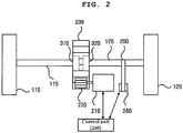
- FIG. 2 is a view illustrating a first power device of a race car according to an example useful for understanding the invention.
- first power device 200 illustrated in FIG. 2 only components related to embodiments are illustrated. Accordingly, it will be understood by an ordinary skilled in the art to which the inventive concept pertains that other general-purpose components may be further included in the first power device 200, in addition to the components illustrated in FIG. 2 .
- the first power device 200 includes an electric motor 210 configured to supply power to the race car 100. Further, the first power device 200 includes a pinion gear 220 connected to the electric motor 210 and a spur gear 230 engaged with the pinion gear 220.
- the race car 100 further includes two rotary shafts 115 and 125 connecting the centers of the two wheels 110 and 120 and the center of the spur gear 230. Further, the two one-way clutches 310 and 320 are installed between the center of the spur gear 230 and the two rotary shafts 115 and 125, respectively.
- the first power device 200 includes at least one encoder 240 for measuring an RPM of at least one of the two wheels 110 and 120. Further, the first power device 200 further includes a pulley 250 connecting the rotary shaft 125 of the wheel 120 and the encoder 240.
- the first power device 200 includes a control unit 260 configured to control the electric motor 210 based on the RPM of the wheel 120 measured by the encoder 240.
- the control unit 260 calculates a speed of the vehicle 100 by using the diameter of the wheel 120 and the RPM of the wheel 120 measured by the encoder 240.
- the control unit 260 measures the speed of the vehicle 100 by using a GPS device (not illustrated) or a sensor included in the race car 100.
- control unit 260 controls the electric motor 210 to add an additional speed to the calculated or measured speed of the race car 100.
- control unit 260 calculates a torque for controlling the electric motor 210.
- a torque valve for giving an acceleration of a (m/s2) to the race car 100 is calculated by using Equation 1.
- T denotes a torque (N*m) and F denotes a force (N).
- T denotes a torque (N*m) and P denotes power (kW or N*m/s).
- a driving system for obtaining a desired torque value by adjusting a gear ratio for a fixed RPM.
- control unit 260 delivers the calculated torque value from the first power device 200 to the wheels 110 and 120 in the form of a rotational force through gears, a chain or a belt.
- control unit 260 delivers the calculated torque value from the electric motor 210 to the wheels 110 and 120 in the form of a rotational force through a pinion gear 220 and a spur gear 230.
- control unit 260 may convert the calculated torque value to a thrust through a propeller included in the third power device 400 and use the converted torque value to accelerate the race car 100.
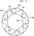
- FIG. 3 is a view illustrating a one-way clutch according to an example useful for understanding the invention.
- Each of the one-way clutches 310 and 320 includes an inner race 330 connected to the rotary shaft 115 and 125 and an outer race 340 connected to the spur gear 230, and includes at least one roller 350 installed between the inner race 330 and the outer race 340 to restrict the rotary shaft 115 and 125 such that the rotary shaft 115 and 125 may rotate only in a travel direction of the race car 100.
- the inner race 330 includes at least one protrusion 332 and 334 that generates friction between the outer race 340 and the roller 350.
- the roller 350 is connected to the protrusion 334 by using a connecting member 352.
- the connecting member 352 includes a spring member.
- the protrusion 332, the roller 350, and the outer race 340 allow the race car 100 to perform non-powered driving by using gravity and do not hamper a progress momentum of the race car 100 when the race car 100 moves forwards. However, when the race car 100 moves backwards while performing non-powered driving by using gravity, frictions are generated between any two of the protrusion 332, the roller 350, and the outer race 340 to restrict rotation of the rotary shaft 115 and 125.
- the race car 100 performs non-powered driving by using gravity in the rightward direction of FIG. 3
- the inner race 330 rotates in a clockwise direction.
- the protrusion 332, the roller 350, and the outer race 340 do not hamper a progress momentum of the race car 100.
- the race car 100 performs non-powered driving by using gravity in the leftward direction of FIG. 3
- the inner race 330 rotates in a counterclockwise direction.
- a reaction occurs between the inner race 330 and the outer race 340 so that the roller 350 may contact an aperture between the protrusion 332 of the inner race 330 and the outer race 340, causing friction.
- the outer race 340 rotates in a clockwise direction if the spur gear 230 rotates.
- the inner race 330 rotates in a clockwise direction like the outer race 340 while a reaction occurs between the inner race 330 and the outer race 340 so that the roller 350 may contact an aperture between the protrusion 332 of the inner race 330 and the outer race 340, causing friction.
- the race car 100 performs non-powered driving by using gravity in the rightward direction of FIG. 3
- the inner race 330 rotates in a clockwise direction.
- the first power device 200 is driven such that the outer race 340 is rotated at an angular speed that is equal to or higher than that of the inner race 330
- the inner race 330 rotates in a clockwise direction like the outer race 340 while a reaction occurs between the inner race 330 and the outer race 340 so that the roller 350 contacts an aperture between the protrusion 332 of the inner race 330 and the outer race 340, causing friction.
- one first power device 200 may supply power to the two wheels 110 and 120 simultaneously when the race car 100 is momentarily accelerated.
- the power of the electric motor 210 is supplied to the two wheels 110 and 120 simultaneously through the one way clutches 310 and 320 connected to the two wheels 110 and 120, respectively, via the pinion gear 220 and the spur gear 230.
- the two wheels 110 and 120 may rotate at different speeds.
- the one-way clutches 310 and 320 do not hamper a progress momentum of the race car 100. Accordingly, the two wheels 110 and 120 may rotate independently.
- one side wheel may maintain a higher RPM than the opposite side wheel so that lowering of the speed of the race car 100 due to friction of a tire may be alleviated.
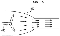
- FIG. 4 is a view illustrating a third power device according to an example useful for understanding the invention.
- the third power device 400 includes a propeller or blade 410 and a ducted fan 420.
- the third power device 400 may include a jet engine configured to generate a thrust by compressing and burning air.
- the race car 100 may include a propeller or blade 410 and a ducted fan 420 that may show an acceleration effect by using a thrust as the third power device 400.
- a plurality of propellers or blades 410 are installed in parallel in the race car 100, a strong thrust may be obtained.
- the efficiency of the third power device 400 may be increased by analyzing a vortex generation point according to a travel of the race car 100 and disposing the propeller or blade 410.
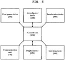
- FIG. 5 is a block diagram illustrating a configuration of a race car according to an embodiment.
- race car 100 illustrated in FIG. 5 only components related to embodiments are illustrated. Accordingly, it will be understood by an ordinary skilled in the art to which the inventive concept pertains that other general-purpose components may be further included in the race car 100, in addition to the components illustrated in FIG. 5 .
- the race car 100 includes a control unit 130, a communication unit 140, and a first power device 200.
- the control unit 130 may include the control unit 260 illustrated in FIG. 2 .
- the communication unit 140 transmits travel information of the race car 100 to a server, and receives a control signal of the first power device 200 for momentary acceleration from the server when the travel information of the race car 100 satisfies a specific condition.
- the control unit 130 controls the first power device 200 based on the control signal received by the communication unit 140.
- the control signal is for controlling the first power device 200 such that the race car 100 travels at a preset speed for a preset period of time.
- the race car 100 includes a display device 150.
- the display device 150 displays an attainment rate of a specific condition.
- the communication unit 140 receives a control signal from the server when the attainment rate of the specific condition displayed on the display device 150 reaches a reference attainment rate.
- the specific condition is at least one of a travel distance of the race car 100 and a travel period of time of the race car 100.
- the display device 150 displays information on at least one of a current travel distance of the race car 100 and a current travel period of time of the race car 100. Further, the display device 150 displays information on at least one of a preset travel distance of the race car 100 and a preset travel period of time of the race car 100 to attain a specific condition.
- control unit 130 performs momentary acceleration by controlling the first power device 200 immediately after the communication unit 140 receives a control signal from the server.
- the race car 100 includes a user input unit 160 for receiving a request for start of momentary acceleration from the driver.
- the race car 100 performs momentary acceleration.
- the communication unit 140 requests approval of momentary acceleration from the server when receiving the request for start of momentary acceleration from the user input unit 160.
- the server identifies whether the race car 100 satisfied the specific condition, and transmits approval information for momentary acceleration. If the communication unit 140 receives approval information for momentary acceleration from the server the race car 100 performs momentary acceleration.
- control unit 130 records the number of times by which the communication unit 140 receives control signals from the server.
- the display device 150 displays the number of times by which the race car 100 performs momentary acceleration.
- the number of times by which the race car 100 may perform momentary acceleration is a value that is obtained by subtracting the number of times by which the race car 100 performs momentary acceleration from the number of times by which the communication unit 140 receives control signals from the server. For example, the number of times by which the race car 100 may perform momentary acceleration is increased by one whenever the communication unit 140 receives a control signal from the server, and is decreased by one whenever the race car 100 performs momentary acceleration.
- the driver of the race car 100 may perform momentary acceleration by paying a specific sum instead of satisfying a specific condition.
- the communication unit 140 requests approval of momentary acceleration from the server when receiving the request for start of momentary acceleration from the user input unit 160.
- the server identifies whether the race car 100 satisfies a specific condition. When the specific condition is not satisfied, the server requests payment for momentary acceleration.
- the communication unit 140 receives a request for payment for momentary acceleration from the server, and transmits approval information for the request for payment to the server.
- the communication unit 140 receives a control signal of the first power device 200 for momentary acceleration from the server, and the control unit 130 performs momentary acceleration by controlling the first power device 200.
- a spectator may present a momentary acceleration item to the race car 100. For example, if the spectator selects a race car 100, to which a momentary acceleration item will be presented, and pays a sum, the server may transmit a control signal of the power device 200 for momentary acceleration.
- the race car 100 is restricted such that momentary acceleration is allowed only in a linear course that does not have a corner within a specific distance.
- the race car 100 or the server may identify a configuration of a course located on the front side of the race car 100. When a corner is present within the specific distance, the race car 100 or the server may restrict momentary acceleration of the race car 100.
- the race car 100 includes a third power device 400.
- the third power device 400 includes at least one of a propeller, a blade, a jet engine, and a ducted fan for obtaining an additional acceleration during momentary acceleration.
- the communication unit 140 receives a control signal for controlling the third power device 400.
- the control unit 130 controls the third power device 400 based on the control signal received by the communication unit 140.
- the race car 100 includes a deceleration device 500 for decreasing a travel speed.
- the deceleration device 500 includes a brake device configured to adjust a speed of the race car 100 by using friction.
- the deceleration device 500 includes a parachute device configured to adjust a speed of the race car 100 by using resistance of air.
- the communication device 140 receives a control signal for decelerating the race car 100 from the server.
- the control unit 130 controls the deceleration device 500 based on the control signal received by the communication unit 140.
- the control signal is for controlling the deceleration device 500 such that the race car travels at a preset speed or less for a preset period of time or less.
- the race car 100 includes a user input unit 160 that may request deceleration of another race car when a specific condition is satisfied.
- the communication unit 140 transmits a request for deceleration of a second race car to the server when receiving the request for deceleration of the second race car from the user input unit 160.
- the server transmits a control signal for deceleration to the communication unit of the race car corresponding to the received request for deceleration.
- the communication unit 140 when the race car 100 satisfies a specific condition, the communication unit 140 receives a control signal for deceleration of the race car 100. For example, when the race car 100 deviates from a specific course or there is a danger of a collision with an obstacle, the communication unit 140 may receive a control signal for deceleration of the race car 100 for safety. Further, even when the race car 100 performs momentary acceleration driving in a site at which there are many corners or obstacles, the communication unit 140 may receive a control signal for deceleration of the race car 100 for safety.
- the communication unit 140 may receive a control signal for deceleration of the race car 100 as a penalty to the race car 100.
- the first power device 200 is used to supply power that is necessary when the race car 100 starts. For example, when the race car 100 performs non-powered driving by using gravity at a corner including a downhill road, a long period of time may be taken until the race car 100 achieves a sufficient acceleration if an inclination of a starting point is low. If there is no inclination at the start point, the race car 100 cannot start with its own force. If the inclination of the start point is steep, it is difficult for the race car 100 to stop at the start point and an accident may occur.
- the first power device 200 may be used in order that the race car 100 may obtain an initial acceleration that is necessary when the race car 100 starts or moves to a steep point.
- the user input unit 160 receives an input of the driver when the race car 100 starts to travel.
- the control unit 130 controls the first power device 200 based on the input of the driver received by the user input unit 160. For example, when the input of the driver is received by the user input unit 160 within a specific period of time from a time point with reference to the start, the control unit 130 performs momentary acceleration by controlling the first power device 200.
- the steps of a method or an algorithm that have been described in relation to the embodiments of the inventive concept may be directly implemented by hardware, may be implemented by a software module executed by hardware, or may be implemented by a combination thereof.
- the storage unit 130 may reside in a random access memory (RAM), a read only memory (ROM), an erasable programmable ROM (EPROM), an electrically erasable programmable ROM (EEPROM), a flash memory, a hard disk, a detachable disk, or a computer readable recording medium in an arbitrary form, which is well known in the art to which the inventive concept pertains.
- the software module may be stored in a cloud server.
- an interest for driving of a race car may be invoked by providing an immediate compensation, for example, in a racing game.
- the race car according to an embodiment may save energy because it does not use power normally and uses power only when it performs momentary acceleration under the control of the server as it performs non-powered driving by using gravity. Further, the race car may safely travel under the control of the server.
- the race car may be made lighter and more compact by replacing a differential gear.
Landscapes
- Engineering & Computer Science (AREA)
- Mechanical Engineering (AREA)
- Transportation (AREA)
- Combustion & Propulsion (AREA)
- Chemical & Material Sciences (AREA)
- General Engineering & Computer Science (AREA)
- Power Engineering (AREA)
- Electric Propulsion And Braking For Vehicles (AREA)
- Tires In General (AREA)
- Arrangement Or Mounting Of Propulsion Units For Vehicles (AREA)
- Transmission Devices (AREA)
- Motor Power Transmission Devices (AREA)
- Hybrid Electric Vehicles (AREA)
- Retarders (AREA)
Claims (8)
- System umfassend:einen Rennwagen (100), der daran angepasst ist, ein nicht angetriebenes Fahren durch Verwenden von Schwerkraft und Momentanbeschleunigung durch Verwenden einer Leistungseinheit durchzuführen; undeinen Server,wobei der Rennwagen (100) eine erste Leistungsvorrichtung (200), die dazu konfiguriert ist, dem Rennwagen (100) Leistung zuzuführen, wenn der Rennwagen (100) momentan beschleunigt wird; zwei Einwegkupplungen (310, 320), die mit der ersten Leistungsvorrichtung (200) verbunden sind; und zwei Räder (110, 120) umfasst, die jeweils mit den zwei Einwegkupplungen (310, 320) verbunden sind,wobei die zwei Räder (110, 120) sich mit verschiedenen Geschwindigkeiten drehen können und mit Leistung versorgt werden, die von der ersten Leistungsvorrichtung (200) durch die jeweils mit den zwei Rädern (110, 120) verbundenen Einwegkupplungen (310, 320) zugeführt wird, wenn der Rennwagen (100) momentan beschleunigt wird, undwobei der Rennwagen (100) ferner umfasst:eine Kommunikationseinheit (140), die dazu konfiguriert ist, eine Fahrinformation des Rennwagens (100) zu dem Server zu übertragen, und ein Steuersignal der ersten Leistungsvorrichtung (200) für eine Momentanbeschleunigung von dem Server empfängt, wenn die Fahrinformation des Rennwagens (100) eine spezifische Bedingung erfüllt; undeine Steuereinheit (260), die dazu konfiguriert ist, die erste Leistungsvorrichtung (200) basierend auf dem durch die Kommunikationseinheit (140) empfangenen Steuersignal zu steuern,wobei das Steuersignal dazu konfiguriert ist, die erste Leistungsvorrichtung (200) derart zu steuern, dass sich der Rennwagen (100) für einen voreingestellten Zeitraum mit einer voreingestellten Geschwindigkeit bewegt,wobei die spezifische Bedingung wenigstens eine einer Fahrtstrecke und eines Fahrtzeitraums des Rennwagen (100) und eines Orts des Rennwagens (100) ist, undwobei der Rennwagen (100) daran angepasst ist, eine Momentanbeschleunigung unter der Steuerung des Servers durchzuführen, undwobei der Server daran angepasst ist, mit einem anderen Rennwagen (100) zu kommunizieren.
- System nach Anspruch 1, wobei die erste Leistungsvorrichtung (200) umfasst:einen Elektromotor (210), der dazu konfiguriert ist, Leistung zuzuführen;ein Ritzelgetriebe (220), das mit dem Elektromotor (210) verbunden ist; undein Stirnradgetriebe (230), das mit dem Ritzelgetriebe (220) in Eingriff ist,wobei der Rennwagen (100) ferner zwei Drehwellen (115, 125) umfasst, die die Zentren der zwei Räder (110, 120) und das Zentrum des Stirnradgetriebes (230) verbinden, undwobei die zwei Einwegkupplungen (310, 320) jeweils zwischen dem Zentrum des Stirnradgetriebes (230) und den zwei Drehwellen (115, 125) installiert sind.
- System nach Anspruch 2, wobei jede der zwei Einwegkupplungen (310, 320) umfasst:einen Innenlaufring (330), der mit der entsprechenden Drehwelle verbunden ist;einen Außenlaufring (340), der mit dem Stirnradgetriebe (230) verbunden ist; undwenigstens eine Rolle (350), die zwischen dem Innenlaufring (330) und dem Außenlaufring (340) installiert und dazu konfiguriert ist, die Drehwelle derart einzuschränken, dass sich die Drehwelle nur in einer Fortschreitrichtung des Rennwagens (100) dreht, undwobei aufgrund der Rolle (350) Reibung zwischen dem Außenlaufring (340) und dem Innenlaufring (330) auftritt, so dass der Innenlaufring (330) sich mit einer Geschwindigkeit dreht, die die gleiche wie jene des Außenlaufrings (340) ist, wenn der Elektromotor (210) derart angetrieben wird, dass der Außenlaufring (340) sich mit einer Geschwindigkeit dreht, die in einer Drehrichtung, die die gleiche wie jene des Innenlaufrings (330) ist, die gleiche wie oder höher als jene des Innenlaufrings (330) ist.
- System nach Anspruch 2, wobei die erste Leistungsvorrichtung (200) umfasst:wenigstens einen Encoder (240), der dazu konfiguriert ist, eine Drehzahl (RPM) von wenigstens einem der zwei Räder (110, 120) zu messen; undeine Steuereinheit (260), die dazu konfiguriert ist, den Elektromotor (210) zu steuern, undwobei die Steuereinheit (260) eine Geschwindigkeit des Rennwagens (100) durch Verwenden der Durchmesser der zwei Räder (110, 120) und der durch den Encoder (240) gemessenen Drehzahl (RPM) berechnet, und den Elektromotor (210) derart steuert, dass eine zusätzliche Geschwindigkeit zu der berechneten Geschwindigkeit hinzugefügt wird, wenn der Rennwagen (100) momentan beschleunigt wird.
- System nach Anspruch 1, ferner umfassend:
wenigstens einen Propeller, ein Blatt, ein Düsentriebwerk und/oder einen Mantelpropeller zum Erhalten einer zusätzlichen Beschleunigung, wenn der Rennwagen (100) momentan beschleunigt wird. - System nach Anspruch 1, ferner umfassend:zwei zweite Leistungsvorrichtungen (202, 204), die mit den zwei Rädern (110, 120) jeweils verbunden sind,wobei die zwei zweiten Leistungsvorrichtungen (202, 204) den zwei Rädern (110, 120) jeweils eine unterschiedliche Leistung zuführen, wenn der Rennwagen (100) momentan beschleunigt wird
- System nach Anspruch 1, ferner umfassend:eine Taste, die dazu konfiguriert ist, eine Performance der Momentanbeschleunigung anzuzeigen; undeine Steuereinheit (260), die dazu konfiguriert ist, die Momentanbeschleunigung durch Steuern der ersten Leistungsvorrichtung (200) durchzuführen, wenn sie eine Eingabe der Taste empfängt.
- System nach Anspruch 6, wobei die Anzahl von Malen, mit denen die Momentanbeschleunigung durchgeführt wird, durch Verwenden der Eingabe der Taste auf einen spezifischen Referenzwert oder weniger eingeschränkt wird.
Applications Claiming Priority (2)
| Application Number | Priority Date | Filing Date | Title |
|---|---|---|---|
| KR1020160123732A KR101680785B1 (ko) | 2016-09-27 | 2016-09-27 | 중력을 이용한 무동력 주행 및 동력장치를 이용한 일시가속을 수행하는 경주용 차량 |
| PCT/KR2017/008820 WO2018062682A1 (ko) | 2016-09-27 | 2017-08-14 | 중력을 이용한 무동력 주행 및 동력장치를 이용한 일시가속을 수행하는 경주용 차량 |
Publications (3)
| Publication Number | Publication Date |
|---|---|
| EP3521089A1 EP3521089A1 (de) | 2019-08-07 |
| EP3521089A4 EP3521089A4 (de) | 2019-09-18 |
| EP3521089B1 true EP3521089B1 (de) | 2020-12-09 |
Family
ID=57706472
Family Applications (1)
| Application Number | Title | Priority Date | Filing Date |
|---|---|---|---|
| EP17856568.5A Active EP3521089B1 (de) | 2016-09-27 | 2017-08-14 | Rennwagen zur durchführung von nicht angetriebenem fahren mittels schwerkraft und momentanbeschleunigung mittels einer antriebseinheit |
Country Status (12)
| Country | Link |
|---|---|
| US (1) | US20190217699A1 (de) |
| EP (1) | EP3521089B1 (de) |
| JP (1) | JP6666474B2 (de) |
| KR (1) | KR101680785B1 (de) |
| CN (1) | CN107878177B (de) |
| AU (1) | AU2017337532B2 (de) |
| CA (1) | CA3037834C (de) |
| ES (1) | ES2841316T3 (de) |
| MY (1) | MY195451A (de) |
| NZ (1) | NZ752062A (de) |
| SG (1) | SG11201809368WA (de) |
| WO (1) | WO2018062682A1 (de) |
Families Citing this family (10)
| Publication number | Priority date | Publication date | Assignee | Title |
|---|---|---|---|---|
| KR101762381B1 (ko) * | 2017-02-13 | 2017-08-04 | (주)모노리스 | 차량 주행용 테마파크 시스템 |
| CN106976498B (zh) * | 2017-05-03 | 2019-04-23 | 新昌县城关宾立机械厂 | 一种基于离心的单驱动恒速行驶的机器人行走平台 |
| CN111094797B (zh) | 2017-09-19 | 2023-10-27 | 庞巴迪动力产品公司 | 针对湿滑驾驶条件而优化的限滑差速器的控制 |
| WO2019058230A1 (en) | 2017-09-19 | 2019-03-28 | Bombardier Recreational Products Inc. | CONTROL OF LIMITED SLIP DIFFERENTIAL BASED ON MOTOR TORQUE |
| RU2768680C2 (ru) * | 2017-09-19 | 2022-03-24 | Бомбардье Рекриэйшенел Продактс Инк. | Управление дифференциалом ограниченного проскальзывания на основе положения средства управления ускорителем |
| CN108551851B (zh) * | 2018-03-13 | 2023-06-30 | 郑世杰 | 一种玉米收获机转弯总成 |
| JP7539778B2 (ja) * | 2020-03-13 | 2024-08-26 | 株式会社シマノ | 人力駆動車用の制御装置、人力駆動車用のコンポーネントに情報を送信するサーバ、人力駆動車に関する通信システム、および、人力駆動車用のコンポーネントの制御方法 |
| CN111572668A (zh) * | 2020-05-25 | 2020-08-25 | 李正芳 | 一种双动力行进车设备 |
| CN113910916B (zh) * | 2020-07-07 | 2023-07-21 | 北京新能源汽车股份有限公司 | 一种赛道模式控制方法、装置、车辆及设备 |
| KR102623572B1 (ko) * | 2021-12-09 | 2024-01-10 | (주)모노리스 | 중력 레이싱 차량용 구동 장치 |
Family Cites Families (14)
| Publication number | Priority date | Publication date | Assignee | Title |
|---|---|---|---|---|
| CN2250446Y (zh) * | 1995-08-04 | 1997-03-26 | 刘成贤 | 摩托车动力传递单向离合器 |
| KR100425277B1 (ko) * | 2000-08-12 | 2004-03-30 | 한승우 | 휠 트랜스밋션 |
| JP4196397B2 (ja) * | 2000-11-16 | 2008-12-17 | マツダ株式会社 | 車両用駆動装置 |
| JP4293545B2 (ja) * | 2003-07-09 | 2009-07-08 | Gkn ドライブライン トルクテクノロジー株式会社 | 減速駆動装置 |
| US7007763B2 (en) | 2003-09-19 | 2006-03-07 | Borgwarner Inc. | Control system for interactive driveline and vehicle control |
| US20070238390A1 (en) * | 2006-04-05 | 2007-10-11 | Kelderhouse Charles D | Model car wheel axle securing plate |
| JP2008089075A (ja) | 2006-10-02 | 2008-04-17 | Toyota Motor Corp | 車両の駆動力配分装置 |
| US8011464B2 (en) * | 2008-07-24 | 2011-09-06 | GM Global Technology Operations LLC | Electric drive system with a selectable one-way clutch |
| JP5267340B2 (ja) * | 2009-06-04 | 2013-08-21 | トヨタ自動車株式会社 | インホイールモータの動力伝達機構 |
| US20110014850A1 (en) * | 2009-07-14 | 2011-01-20 | David Kennedy | Gravity Racing Car |
| JP2011102112A (ja) * | 2009-10-13 | 2011-05-26 | Ntn Corp | 電気自動車 |
| JP5657068B2 (ja) | 2011-12-22 | 2015-01-21 | 本田技研工業株式会社 | 車両用駆動装置 |
| BR202013021112U2 (pt) * | 2013-08-19 | 2015-07-28 | Francisco Carlos Rodrigues Cruz | Disposição construtiva aplicada em carrinho de rolimã elétrico |
| JP6198614B2 (ja) * | 2014-01-22 | 2017-09-20 | 三菱電機株式会社 | 走行支援装置、サーバ装置および走行支援システム |
-
2016
- 2016-09-27 KR KR1020160123732A patent/KR101680785B1/ko active Active
-
2017
- 2017-03-30 CN CN201710201125.4A patent/CN107878177B/zh active Active
- 2017-08-14 SG SG11201809368WA patent/SG11201809368WA/en unknown
- 2017-08-14 AU AU2017337532A patent/AU2017337532B2/en active Active
- 2017-08-14 EP EP17856568.5A patent/EP3521089B1/de active Active
- 2017-08-14 MY MYPI2018002762A patent/MY195451A/en unknown
- 2017-08-14 NZ NZ752062A patent/NZ752062A/en unknown
- 2017-08-14 JP JP2018561234A patent/JP6666474B2/ja active Active
- 2017-08-14 WO PCT/KR2017/008820 patent/WO2018062682A1/ko not_active Ceased
- 2017-08-14 CA CA3037834A patent/CA3037834C/en active Active
- 2017-08-14 ES ES17856568T patent/ES2841316T3/es active Active
-
2019
- 2019-03-21 US US16/360,889 patent/US20190217699A1/en not_active Abandoned
Non-Patent Citations (2)
| Title |
|---|
| CALDERON ALFONSO GAGO ET AL: "GPRS telemetry system for high-efficiency electric competition vehicles", 2013 WORLD ELECTRIC VEHICLE SYMPOSIUM AND EXHIBITION (EVS27), IEEE, 17 November 2013 (2013-11-17), pages 1 - 7, XP032654064, DOI: 10.1109/EVS.2013.6914788 * |
| ESPELAND ASLAK BRAGE ET AL: "Development and Construction of Vehicle for Participation in the Shell Eco-marathon Competition", 8 November 2012 (2012-11-08), pages 283 - 287, XP055684478, Retrieved from the Internet <URL:https://pdfs.semanticscholar.org/bdd2/42ef86d84b548429f267416c9a8a407156a4.pdf> [retrieved on 20200408] * |
Also Published As
| Publication number | Publication date |
|---|---|
| JP6666474B2 (ja) | 2020-03-13 |
| AU2017337532B2 (en) | 2020-06-11 |
| US20190217699A1 (en) | 2019-07-18 |
| WO2018062682A1 (ko) | 2018-04-05 |
| CA3037834C (en) | 2021-08-03 |
| NZ752062A (en) | 2020-05-29 |
| CN107878177B (zh) | 2019-04-02 |
| KR101680785B1 (ko) | 2016-11-29 |
| AU2017337532A1 (en) | 2019-04-18 |
| ES2841316T3 (es) | 2021-07-08 |
| EP3521089A1 (de) | 2019-08-07 |
| EP3521089A4 (de) | 2019-09-18 |
| CN107878177A (zh) | 2018-04-06 |
| JP2019526017A (ja) | 2019-09-12 |
| MY195451A (en) | 2023-01-24 |
| CA3037834A1 (en) | 2018-04-05 |
| SG11201809368WA (en) | 2018-11-29 |
Similar Documents
| Publication | Publication Date | Title |
|---|---|---|
| EP3521089B1 (de) | Rennwagen zur durchführung von nicht angetriebenem fahren mittels schwerkraft und momentanbeschleunigung mittels einer antriebseinheit | |
| US10836427B2 (en) | Drive configurations for skid steered vehicles | |
| CN115610238B (zh) | 用于控制车辆的车轮的速度差的系统和方法 | |
| US8172022B2 (en) | Energy recovery systems for vehicles and vehicle wheels comprising the same | |
| JP6477533B2 (ja) | ハイブリッド車両の制御装置 | |
| EP2218634A1 (de) | Fahrrad-Übertragungssystem | |
| JP2007139011A (ja) | 車軸間トルク発生装置 | |
| JP2011237019A (ja) | 左右輪駆動装置 | |
| EP3587235A1 (de) | Verfahren zur bereitstellung einer elektrischen antriebsunterstützung in einem pedalgetriebenen fahrzeug und steuergerät zur implementierung davon | |
| US12024160B2 (en) | Systems and methods for performing vehicle yaw in an electric vehicle | |
| KR20220088482A (ko) | 조향 시스템 및 차량 | |
| CN101867339A (zh) | 一种电子机械制动系统的电机控制方法 | |
| JP7511914B2 (ja) | 車両ホイールアッセンブリ | |
| CN102537321A (zh) | 电辅助可变k因子控制 | |
| HK40012434B (en) | Race car for performing non-powered driving by using gravity and momentary acceleration by using power unit | |
| HK40012434A (en) | Race car for performing non-powered driving by using gravity and momentary acceleration by using power unit | |
| US2750812A (en) | Mirone | |
| CN114294412A (zh) | 一种纯电动商用车、控制系统、起步档位控制方法 | |
| JP2009057874A (ja) | 駆動力制御装置 | |
| JP2013209046A (ja) | 制御システム | |
| JP2006057745A (ja) | 差動装置 | |
| US11919332B2 (en) | Vehicle wheel assembly and method | |
| JP2005184995A (ja) | 車両の制御装置 | |
| JP2009057875A (ja) | 駆動力制御装置 | |
| JP2007216746A (ja) | 車両用トルク配分装置 |
Legal Events
| Date | Code | Title | Description |
|---|---|---|---|
| STAA | Information on the status of an ep patent application or granted ep patent |
Free format text: STATUS: THE INTERNATIONAL PUBLICATION HAS BEEN MADE |
|
| PUAI | Public reference made under article 153(3) epc to a published international application that has entered the european phase |
Free format text: ORIGINAL CODE: 0009012 |
|
| STAA | Information on the status of an ep patent application or granted ep patent |
Free format text: STATUS: REQUEST FOR EXAMINATION WAS MADE |
|
| 17P | Request for examination filed |
Effective date: 20190424 |
|
| AK | Designated contracting states |
Kind code of ref document: A1 Designated state(s): AL AT BE BG CH CY CZ DE DK EE ES FI FR GB GR HR HU IE IS IT LI LT LU LV MC MK MT NL NO PL PT RO RS SE SI SK SM TR |
|
| AX | Request for extension of the european patent |
Extension state: BA ME |
|
| A4 | Supplementary search report drawn up and despatched |
Effective date: 20190819 |
|
| RIC1 | Information provided on ipc code assigned before grant |
Ipc: F16H 3/10 20060101ALI20190812BHEP Ipc: B60K 17/35 20060101ALI20190812BHEP Ipc: F16D 25/10 20060101ALI20190812BHEP Ipc: F16H 19/04 20060101ALI20190812BHEP Ipc: B60K 1/00 20060101ALN20190812BHEP Ipc: B60L 15/20 20060101ALI20190812BHEP Ipc: F16D 41/06 20060101ALI20190812BHEP Ipc: B60K 6/383 20071001ALI20190812BHEP Ipc: B60K 7/00 20060101AFI20190812BHEP |
|
| DAV | Request for validation of the european patent (deleted) | ||
| DAX | Request for extension of the european patent (deleted) | ||
| STAA | Information on the status of an ep patent application or granted ep patent |
Free format text: STATUS: EXAMINATION IS IN PROGRESS |
|
| 17Q | First examination report despatched |
Effective date: 20200430 |
|
| REG | Reference to a national code |
Ref country code: HK Ref legal event code: DE Ref document number: 40012434 Country of ref document: HK |
|
| GRAP | Despatch of communication of intention to grant a patent |
Free format text: ORIGINAL CODE: EPIDOSNIGR1 |
|
| STAA | Information on the status of an ep patent application or granted ep patent |
Free format text: STATUS: GRANT OF PATENT IS INTENDED |
|
| RIC1 | Information provided on ipc code assigned before grant |
Ipc: B60K 7/00 20060101AFI20200825BHEP Ipc: F16D 25/10 20060101ALI20200825BHEP Ipc: B60K 1/00 20060101ALN20200825BHEP Ipc: F16H 19/04 20060101ALI20200825BHEP Ipc: F16H 3/10 20060101ALI20200825BHEP Ipc: B60K 17/35 20060101ALI20200825BHEP Ipc: B60L 15/40 20060101ALI20200825BHEP Ipc: F16D 41/06 20060101ALI20200825BHEP Ipc: B60K 6/383 20071001ALI20200825BHEP Ipc: B60L 15/20 20060101ALI20200825BHEP |
|
| INTG | Intention to grant announced |
Effective date: 20200911 |
|
| RIC1 | Information provided on ipc code assigned before grant |
Ipc: F16H 3/10 20060101ALI20200902BHEP Ipc: F16H 19/04 20060101ALI20200902BHEP Ipc: F16D 41/06 20060101ALI20200902BHEP Ipc: B60K 1/00 20060101ALN20200902BHEP Ipc: F16D 25/10 20060101ALI20200902BHEP Ipc: B60K 6/383 20071001ALI20200902BHEP Ipc: B60K 17/35 20060101ALI20200902BHEP Ipc: B60L 15/40 20060101ALI20200902BHEP Ipc: B60K 7/00 20060101AFI20200902BHEP Ipc: B60L 15/20 20060101ALI20200902BHEP |
|
| GRAS | Grant fee paid |
Free format text: ORIGINAL CODE: EPIDOSNIGR3 |
|
| GRAA | (expected) grant |
Free format text: ORIGINAL CODE: 0009210 |
|
| STAA | Information on the status of an ep patent application or granted ep patent |
Free format text: STATUS: THE PATENT HAS BEEN GRANTED |
|
| AK | Designated contracting states |
Kind code of ref document: B1 Designated state(s): AL AT BE BG CH CY CZ DE DK EE ES FI FR GB GR HR HU IE IS IT LI LT LU LV MC MK MT NL NO PL PT RO RS SE SI SK SM TR |
|
| REG | Reference to a national code |
Ref country code: GB Ref legal event code: FG4D |
|
| REG | Reference to a national code |
Ref country code: AT Ref legal event code: REF Ref document number: 1343070 Country of ref document: AT Kind code of ref document: T Effective date: 20201215 Ref country code: CH Ref legal event code: EP |
|
| REG | Reference to a national code |
Ref country code: DE Ref legal event code: R096 Ref document number: 602017029437 Country of ref document: DE |
|
| REG | Reference to a national code |
Ref country code: IE Ref legal event code: FG4D |
|
| REG | Reference to a national code |
Ref country code: NL Ref legal event code: FP |
|
| PG25 | Lapsed in a contracting state [announced via postgrant information from national office to epo] |
Ref country code: FI Free format text: LAPSE BECAUSE OF FAILURE TO SUBMIT A TRANSLATION OF THE DESCRIPTION OR TO PAY THE FEE WITHIN THE PRESCRIBED TIME-LIMIT Effective date: 20201209 Ref country code: RS Free format text: LAPSE BECAUSE OF FAILURE TO SUBMIT A TRANSLATION OF THE DESCRIPTION OR TO PAY THE FEE WITHIN THE PRESCRIBED TIME-LIMIT Effective date: 20201209 Ref country code: NO Free format text: LAPSE BECAUSE OF FAILURE TO SUBMIT A TRANSLATION OF THE DESCRIPTION OR TO PAY THE FEE WITHIN THE PRESCRIBED TIME-LIMIT Effective date: 20210309 Ref country code: GR Free format text: LAPSE BECAUSE OF FAILURE TO SUBMIT A TRANSLATION OF THE DESCRIPTION OR TO PAY THE FEE WITHIN THE PRESCRIBED TIME-LIMIT Effective date: 20210310 |
|
| REG | Reference to a national code |
Ref country code: AT Ref legal event code: MK05 Ref document number: 1343070 Country of ref document: AT Kind code of ref document: T Effective date: 20201209 |
|
| PG25 | Lapsed in a contracting state [announced via postgrant information from national office to epo] |
Ref country code: BG Free format text: LAPSE BECAUSE OF FAILURE TO SUBMIT A TRANSLATION OF THE DESCRIPTION OR TO PAY THE FEE WITHIN THE PRESCRIBED TIME-LIMIT Effective date: 20210309 Ref country code: LV Free format text: LAPSE BECAUSE OF FAILURE TO SUBMIT A TRANSLATION OF THE DESCRIPTION OR TO PAY THE FEE WITHIN THE PRESCRIBED TIME-LIMIT Effective date: 20201209 Ref country code: SE Free format text: LAPSE BECAUSE OF FAILURE TO SUBMIT A TRANSLATION OF THE DESCRIPTION OR TO PAY THE FEE WITHIN THE PRESCRIBED TIME-LIMIT Effective date: 20201209 |
|
| PG25 | Lapsed in a contracting state [announced via postgrant information from national office to epo] |
Ref country code: HR Free format text: LAPSE BECAUSE OF FAILURE TO SUBMIT A TRANSLATION OF THE DESCRIPTION OR TO PAY THE FEE WITHIN THE PRESCRIBED TIME-LIMIT Effective date: 20201209 |
|
| REG | Reference to a national code |
Ref country code: ES Ref legal event code: FG2A Ref document number: 2841316 Country of ref document: ES Kind code of ref document: T3 Effective date: 20210708 |
|
| REG | Reference to a national code |
Ref country code: LT Ref legal event code: MG9D |
|
| PG25 | Lapsed in a contracting state [announced via postgrant information from national office to epo] |
Ref country code: SM Free format text: LAPSE BECAUSE OF FAILURE TO SUBMIT A TRANSLATION OF THE DESCRIPTION OR TO PAY THE FEE WITHIN THE PRESCRIBED TIME-LIMIT Effective date: 20201209 Ref country code: LT Free format text: LAPSE BECAUSE OF FAILURE TO SUBMIT A TRANSLATION OF THE DESCRIPTION OR TO PAY THE FEE WITHIN THE PRESCRIBED TIME-LIMIT Effective date: 20201209 Ref country code: EE Free format text: LAPSE BECAUSE OF FAILURE TO SUBMIT A TRANSLATION OF THE DESCRIPTION OR TO PAY THE FEE WITHIN THE PRESCRIBED TIME-LIMIT Effective date: 20201209 Ref country code: CZ Free format text: LAPSE BECAUSE OF FAILURE TO SUBMIT A TRANSLATION OF THE DESCRIPTION OR TO PAY THE FEE WITHIN THE PRESCRIBED TIME-LIMIT Effective date: 20201209 Ref country code: SK Free format text: LAPSE BECAUSE OF FAILURE TO SUBMIT A TRANSLATION OF THE DESCRIPTION OR TO PAY THE FEE WITHIN THE PRESCRIBED TIME-LIMIT Effective date: 20201209 Ref country code: PT Free format text: LAPSE BECAUSE OF FAILURE TO SUBMIT A TRANSLATION OF THE DESCRIPTION OR TO PAY THE FEE WITHIN THE PRESCRIBED TIME-LIMIT Effective date: 20210409 Ref country code: RO Free format text: LAPSE BECAUSE OF FAILURE TO SUBMIT A TRANSLATION OF THE DESCRIPTION OR TO PAY THE FEE WITHIN THE PRESCRIBED TIME-LIMIT Effective date: 20201209 |
|
| PG25 | Lapsed in a contracting state [announced via postgrant information from national office to epo] |
Ref country code: PL Free format text: LAPSE BECAUSE OF FAILURE TO SUBMIT A TRANSLATION OF THE DESCRIPTION OR TO PAY THE FEE WITHIN THE PRESCRIBED TIME-LIMIT Effective date: 20201209 Ref country code: AT Free format text: LAPSE BECAUSE OF FAILURE TO SUBMIT A TRANSLATION OF THE DESCRIPTION OR TO PAY THE FEE WITHIN THE PRESCRIBED TIME-LIMIT Effective date: 20201209 |
|
| REG | Reference to a national code |
Ref country code: DE Ref legal event code: R097 Ref document number: 602017029437 Country of ref document: DE |
|
| PG25 | Lapsed in a contracting state [announced via postgrant information from national office to epo] |
Ref country code: IS Free format text: LAPSE BECAUSE OF FAILURE TO SUBMIT A TRANSLATION OF THE DESCRIPTION OR TO PAY THE FEE WITHIN THE PRESCRIBED TIME-LIMIT Effective date: 20210409 |
|
| PLBE | No opposition filed within time limit |
Free format text: ORIGINAL CODE: 0009261 |
|
| STAA | Information on the status of an ep patent application or granted ep patent |
Free format text: STATUS: NO OPPOSITION FILED WITHIN TIME LIMIT |
|
| PG25 | Lapsed in a contracting state [announced via postgrant information from national office to epo] |
Ref country code: AL Free format text: LAPSE BECAUSE OF FAILURE TO SUBMIT A TRANSLATION OF THE DESCRIPTION OR TO PAY THE FEE WITHIN THE PRESCRIBED TIME-LIMIT Effective date: 20201209 |
|
| 26N | No opposition filed |
Effective date: 20210910 |
|
| PG25 | Lapsed in a contracting state [announced via postgrant information from national office to epo] |
Ref country code: DK Free format text: LAPSE BECAUSE OF FAILURE TO SUBMIT A TRANSLATION OF THE DESCRIPTION OR TO PAY THE FEE WITHIN THE PRESCRIBED TIME-LIMIT Effective date: 20201209 Ref country code: SI Free format text: LAPSE BECAUSE OF FAILURE TO SUBMIT A TRANSLATION OF THE DESCRIPTION OR TO PAY THE FEE WITHIN THE PRESCRIBED TIME-LIMIT Effective date: 20201209 |
|
| REG | Reference to a national code |
Ref country code: CH Ref legal event code: PL |
|
| PG25 | Lapsed in a contracting state [announced via postgrant information from national office to epo] |
Ref country code: MC Free format text: LAPSE BECAUSE OF FAILURE TO SUBMIT A TRANSLATION OF THE DESCRIPTION OR TO PAY THE FEE WITHIN THE PRESCRIBED TIME-LIMIT Effective date: 20201209 |
|
| REG | Reference to a national code |
Ref country code: NL Ref legal event code: MM Effective date: 20210901 |
|
| REG | Reference to a national code |
Ref country code: BE Ref legal event code: MM Effective date: 20210831 |
|
| PG25 | Lapsed in a contracting state [announced via postgrant information from national office to epo] |
Ref country code: LI Free format text: LAPSE BECAUSE OF NON-PAYMENT OF DUE FEES Effective date: 20210831 Ref country code: CH Free format text: LAPSE BECAUSE OF NON-PAYMENT OF DUE FEES Effective date: 20210831 |
|
| PG25 | Lapsed in a contracting state [announced via postgrant information from national office to epo] |
Ref country code: IS Free format text: LAPSE BECAUSE OF FAILURE TO SUBMIT A TRANSLATION OF THE DESCRIPTION OR TO PAY THE FEE WITHIN THE PRESCRIBED TIME-LIMIT Effective date: 20210409 Ref country code: LU Free format text: LAPSE BECAUSE OF NON-PAYMENT OF DUE FEES Effective date: 20210814 |
|
| PG25 | Lapsed in a contracting state [announced via postgrant information from national office to epo] |
Ref country code: NL Free format text: LAPSE BECAUSE OF NON-PAYMENT OF DUE FEES Effective date: 20210901 |
|
| PG25 | Lapsed in a contracting state [announced via postgrant information from national office to epo] |
Ref country code: IE Free format text: LAPSE BECAUSE OF NON-PAYMENT OF DUE FEES Effective date: 20210814 Ref country code: BE Free format text: LAPSE BECAUSE OF NON-PAYMENT OF DUE FEES Effective date: 20210831 |
|
| REG | Reference to a national code |
Ref country code: ES Ref legal event code: FD2A Effective date: 20220927 |
|
| PG25 | Lapsed in a contracting state [announced via postgrant information from national office to epo] |
Ref country code: ES Free format text: LAPSE BECAUSE OF NON-PAYMENT OF DUE FEES Effective date: 20210815 |
|
| PG25 | Lapsed in a contracting state [announced via postgrant information from national office to epo] |
Ref country code: IT Free format text: LAPSE BECAUSE OF NON-PAYMENT OF DUE FEES Effective date: 20210814 |
|
| PG25 | Lapsed in a contracting state [announced via postgrant information from national office to epo] |
Ref country code: CY Free format text: LAPSE BECAUSE OF FAILURE TO SUBMIT A TRANSLATION OF THE DESCRIPTION OR TO PAY THE FEE WITHIN THE PRESCRIBED TIME-LIMIT Effective date: 20201209 |
|
| PG25 | Lapsed in a contracting state [announced via postgrant information from national office to epo] |
Ref country code: HU Free format text: LAPSE BECAUSE OF FAILURE TO SUBMIT A TRANSLATION OF THE DESCRIPTION OR TO PAY THE FEE WITHIN THE PRESCRIBED TIME-LIMIT; INVALID AB INITIO Effective date: 20170814 |
|
| PG25 | Lapsed in a contracting state [announced via postgrant information from national office to epo] |
Ref country code: MK Free format text: LAPSE BECAUSE OF FAILURE TO SUBMIT A TRANSLATION OF THE DESCRIPTION OR TO PAY THE FEE WITHIN THE PRESCRIBED TIME-LIMIT Effective date: 20201209 |
|
| PG25 | Lapsed in a contracting state [announced via postgrant information from national office to epo] |
Ref country code: TR Free format text: LAPSE BECAUSE OF FAILURE TO SUBMIT A TRANSLATION OF THE DESCRIPTION OR TO PAY THE FEE WITHIN THE PRESCRIBED TIME-LIMIT Effective date: 20201209 |
|
| PG25 | Lapsed in a contracting state [announced via postgrant information from national office to epo] |
Ref country code: MT Free format text: LAPSE BECAUSE OF FAILURE TO SUBMIT A TRANSLATION OF THE DESCRIPTION OR TO PAY THE FEE WITHIN THE PRESCRIBED TIME-LIMIT Effective date: 20201209 |
|
| PGFP | Annual fee paid to national office [announced via postgrant information from national office to epo] |
Ref country code: DE Payment date: 20250724 Year of fee payment: 9 |
|
| PGFP | Annual fee paid to national office [announced via postgrant information from national office to epo] |
Ref country code: GB Payment date: 20250724 Year of fee payment: 9 |
|
| PGFP | Annual fee paid to national office [announced via postgrant information from national office to epo] |
Ref country code: FR Payment date: 20250725 Year of fee payment: 9 |