EP3520190B1 - Anordnung und verfahren zum abdichten eines drahtbündels - Google Patents
Anordnung und verfahren zum abdichten eines drahtbündels Download PDFInfo
- Publication number
- EP3520190B1 EP3520190B1 EP17783672.3A EP17783672A EP3520190B1 EP 3520190 B1 EP3520190 B1 EP 3520190B1 EP 17783672 A EP17783672 A EP 17783672A EP 3520190 B1 EP3520190 B1 EP 3520190B1
- Authority
- EP
- European Patent Office
- Prior art keywords
- wires
- assembly
- sealant
- sealing assembly
- sealing
- Prior art date
- Legal status (The legal status is an assumption and is not a legal conclusion. Google has not performed a legal analysis and makes no representation as to the accuracy of the status listed.)
- Active
Links
- 238000007789 sealing Methods 0.000 title claims description 83
- 238000000034 method Methods 0.000 title description 9
- 239000012812 sealant material Substances 0.000 claims description 37
- 239000004020 conductor Substances 0.000 claims description 27
- 238000009826 distribution Methods 0.000 claims description 8
- 239000000565 sealant Substances 0.000 description 61
- 238000010438 heat treatment Methods 0.000 description 14
- 239000000463 material Substances 0.000 description 13
- 229920000098 polyolefin Polymers 0.000 description 9
- 239000004698 Polyethylene Substances 0.000 description 8
- 239000005038 ethylene vinyl acetate Substances 0.000 description 8
- 229920001200 poly(ethylene-vinyl acetate) Polymers 0.000 description 8
- 229920002647 polyamide Polymers 0.000 description 8
- 229920000573 polyethylene Polymers 0.000 description 8
- 239000004952 Polyamide Substances 0.000 description 7
- 230000006835 compression Effects 0.000 description 7
- 238000007906 compression Methods 0.000 description 7
- 239000000203 mixture Substances 0.000 description 6
- 239000000945 filler Substances 0.000 description 5
- 239000002654 heat shrinkable material Substances 0.000 description 5
- 230000005291 magnetic effect Effects 0.000 description 5
- 229910052751 metal Inorganic materials 0.000 description 5
- 239000002184 metal Substances 0.000 description 5
- PXHVJJICTQNCMI-UHFFFAOYSA-N Nickel Chemical compound [Ni] PXHVJJICTQNCMI-UHFFFAOYSA-N 0.000 description 4
- -1 polyethylene Polymers 0.000 description 4
- 229920000642 polymer Polymers 0.000 description 4
- RYGMFSIKBFXOCR-UHFFFAOYSA-N Copper Chemical compound [Cu] RYGMFSIKBFXOCR-UHFFFAOYSA-N 0.000 description 3
- 239000011358 absorbing material Substances 0.000 description 3
- 239000000654 additive Substances 0.000 description 3
- 239000003963 antioxidant agent Substances 0.000 description 3
- 230000000712 assembly Effects 0.000 description 3
- 238000000429 assembly Methods 0.000 description 3
- 229920005601 base polymer Polymers 0.000 description 3
- 239000002131 composite material Substances 0.000 description 3
- 229910052802 copper Inorganic materials 0.000 description 3
- 239000010949 copper Substances 0.000 description 3
- KUNSUQLRTQLHQQ-UHFFFAOYSA-N copper tin Chemical compound [Cu].[Sn] KUNSUQLRTQLHQQ-UHFFFAOYSA-N 0.000 description 3
- 239000011888 foil Substances 0.000 description 3
- 239000012634 fragment Substances 0.000 description 3
- 238000002844 melting Methods 0.000 description 3
- 230000008018 melting Effects 0.000 description 3
- 239000003381 stabilizer Substances 0.000 description 3
- KOMNUTZXSVSERR-UHFFFAOYSA-N 1,3,5-tris(prop-2-enyl)-1,3,5-triazinane-2,4,6-trione Chemical compound C=CCN1C(=O)N(CC=C)C(=O)N(CC=C)C1=O KOMNUTZXSVSERR-UHFFFAOYSA-N 0.000 description 2
- BJELTSYBAHKXRW-UHFFFAOYSA-N 2,4,6-triallyloxy-1,3,5-triazine Chemical compound C=CCOC1=NC(OCC=C)=NC(OCC=C)=N1 BJELTSYBAHKXRW-UHFFFAOYSA-N 0.000 description 2
- OKTJSMMVPCPJKN-UHFFFAOYSA-N Carbon Chemical compound [C] OKTJSMMVPCPJKN-UHFFFAOYSA-N 0.000 description 2
- DAKWPKUUDNSNPN-UHFFFAOYSA-N Trimethylolpropane triacrylate Chemical compound C=CC(=O)OCC(CC)(COC(=O)C=C)COC(=O)C=C DAKWPKUUDNSNPN-UHFFFAOYSA-N 0.000 description 2
- OKKRPWIIYQTPQF-UHFFFAOYSA-N Trimethylolpropane trimethacrylate Chemical compound CC(=C)C(=O)OCC(CC)(COC(=O)C(C)=C)COC(=O)C(C)=C OKKRPWIIYQTPQF-UHFFFAOYSA-N 0.000 description 2
- 230000032683 aging Effects 0.000 description 2
- 229910045601 alloy Inorganic materials 0.000 description 2
- 239000000956 alloy Substances 0.000 description 2
- 229910052782 aluminium Inorganic materials 0.000 description 2
- XAGFODPZIPBFFR-UHFFFAOYSA-N aluminium Chemical compound [Al] XAGFODPZIPBFFR-UHFFFAOYSA-N 0.000 description 2
- 229910052799 carbon Inorganic materials 0.000 description 2
- 239000006229 carbon black Substances 0.000 description 2
- 239000003795 chemical substances by application Substances 0.000 description 2
- 239000003431 cross linking reagent Substances 0.000 description 2
- 229920000840 ethylene tetrafluoroethylene copolymer Polymers 0.000 description 2
- 239000003302 ferromagnetic material Substances 0.000 description 2
- 230000001939 inductive effect Effects 0.000 description 2
- 238000009413 insulation Methods 0.000 description 2
- 238000000465 moulding Methods 0.000 description 2
- 229910052759 nickel Inorganic materials 0.000 description 2
- 150000002978 peroxides Chemical class 0.000 description 2
- 229920000139 polyethylene terephthalate Polymers 0.000 description 2
- 239000005020 polyethylene terephthalate Substances 0.000 description 2
- 229920002725 thermoplastic elastomer Polymers 0.000 description 2
- 238000012546 transfer Methods 0.000 description 2
- FRWYFWZENXDZMU-UHFFFAOYSA-N 2-iodoquinoline Chemical compound C1=CC=CC2=NC(I)=CC=C21 FRWYFWZENXDZMU-UHFFFAOYSA-N 0.000 description 1
- 229910000838 Al alloy Inorganic materials 0.000 description 1
- 229910052582 BN Inorganic materials 0.000 description 1
- PZNSFCLAULLKQX-UHFFFAOYSA-N Boron nitride Chemical compound N#B PZNSFCLAULLKQX-UHFFFAOYSA-N 0.000 description 1
- 229910001369 Brass Inorganic materials 0.000 description 1
- 229910000906 Bronze Inorganic materials 0.000 description 1
- NPXOKRUENSOPAO-UHFFFAOYSA-N Raney nickel Chemical compound [Al].[Ni] NPXOKRUENSOPAO-UHFFFAOYSA-N 0.000 description 1
- 229910052581 Si3N4 Inorganic materials 0.000 description 1
- 229910000831 Steel Inorganic materials 0.000 description 1
- 239000002390 adhesive tape Substances 0.000 description 1
- LTPBRCUWZOMYOC-UHFFFAOYSA-N beryllium oxide Inorganic materials O=[Be] LTPBRCUWZOMYOC-UHFFFAOYSA-N 0.000 description 1
- 239000010951 brass Substances 0.000 description 1
- 210000000481 breast Anatomy 0.000 description 1
- 239000010974 bronze Substances 0.000 description 1
- 239000000788 chromium alloy Substances 0.000 description 1
- PMHQVHHXPFUNSP-UHFFFAOYSA-M copper(1+);methylsulfanylmethane;bromide Chemical compound Br[Cu].CSC PMHQVHHXPFUNSP-UHFFFAOYSA-M 0.000 description 1
- 230000008878 coupling Effects 0.000 description 1
- 238000010168 coupling process Methods 0.000 description 1
- 238000005859 coupling reaction Methods 0.000 description 1
- 238000004132 cross linking Methods 0.000 description 1
- 230000005574 cross-species transmission Effects 0.000 description 1
- 239000011243 crosslinked material Substances 0.000 description 1
- 125000003438 dodecyl group Chemical group [H]C([H])([H])C([H])([H])C([H])([H])C([H])([H])C([H])([H])C([H])([H])C([H])([H])C([H])([H])C([H])([H])C([H])([H])C([H])([H])C([H])([H])* 0.000 description 1
- 229920001971 elastomer Polymers 0.000 description 1
- 238000010292 electrical insulation Methods 0.000 description 1
- 239000012777 electrically insulating material Substances 0.000 description 1
- 230000007613 environmental effect Effects 0.000 description 1
- 238000001125 extrusion Methods 0.000 description 1
- 229920002313 fluoropolymer Polymers 0.000 description 1
- 239000004811 fluoropolymer Substances 0.000 description 1
- 239000004088 foaming agent Substances 0.000 description 1
- VOZRXNHHFUQHIL-UHFFFAOYSA-N glycidyl methacrylate Chemical compound CC(=C)C(=O)OCC1CO1 VOZRXNHHFUQHIL-UHFFFAOYSA-N 0.000 description 1
- 239000012943 hotmelt Substances 0.000 description 1
- 238000003780 insertion Methods 0.000 description 1
- 230000037431 insertion Effects 0.000 description 1
- CPLXHLVBOLITMK-UHFFFAOYSA-N magnesium oxide Inorganic materials [Mg]=O CPLXHLVBOLITMK-UHFFFAOYSA-N 0.000 description 1
- 239000000395 magnesium oxide Substances 0.000 description 1
- AXZKOIWUVFPNLO-UHFFFAOYSA-N magnesium;oxygen(2-) Chemical compound [O-2].[Mg+2] AXZKOIWUVFPNLO-UHFFFAOYSA-N 0.000 description 1
- 239000000696 magnetic material Substances 0.000 description 1
- FPYJFEHAWHCUMM-UHFFFAOYSA-N maleic anhydride Chemical compound O=C1OC(=O)C=C1 FPYJFEHAWHCUMM-UHFFFAOYSA-N 0.000 description 1
- 238000004519 manufacturing process Methods 0.000 description 1
- 238000012986 modification Methods 0.000 description 1
- 230000004048 modification Effects 0.000 description 1
- 229910000623 nickel–chromium alloy Inorganic materials 0.000 description 1
- 230000003534 oscillatory effect Effects 0.000 description 1
- 238000013021 overheating Methods 0.000 description 1
- TWNQGVIAIRXVLR-UHFFFAOYSA-N oxo(oxoalumanyloxy)alumane Chemical compound O=[Al]O[Al]=O TWNQGVIAIRXVLR-UHFFFAOYSA-N 0.000 description 1
- 239000002530 phenolic antioxidant Substances 0.000 description 1
- 230000001737 promoting effect Effects 0.000 description 1
- 238000005096 rolling process Methods 0.000 description 1
- 150000004756 silanes Chemical class 0.000 description 1
- HBMJWWWQQXIZIP-UHFFFAOYSA-N silicon carbide Chemical compound [Si+]#[C-] HBMJWWWQQXIZIP-UHFFFAOYSA-N 0.000 description 1
- 229910010271 silicon carbide Inorganic materials 0.000 description 1
- HQVNEWCFYHHQES-UHFFFAOYSA-N silicon nitride Chemical compound N12[Si]34N5[Si]62N3[Si]51N64 HQVNEWCFYHHQES-UHFFFAOYSA-N 0.000 description 1
- 239000010935 stainless steel Substances 0.000 description 1
- 229910001220 stainless steel Inorganic materials 0.000 description 1
- 125000004079 stearyl group Chemical group [H]C([*])([H])C([H])([H])C([H])([H])C([H])([H])C([H])([H])C([H])([H])C([H])([H])C([H])([H])C([H])([H])C([H])([H])C([H])([H])C([H])([H])C([H])([H])C([H])([H])C([H])([H])C([H])([H])C([H])([H])C([H])([H])[H] 0.000 description 1
- 239000010959 steel Substances 0.000 description 1
- 239000000126 substance Substances 0.000 description 1
- 229920001169 thermoplastic Polymers 0.000 description 1
- 239000004416 thermosoftening plastic Substances 0.000 description 1
- 150000007970 thio esters Chemical class 0.000 description 1
- XLYOFNOQVPJJNP-UHFFFAOYSA-N water Substances O XLYOFNOQVPJJNP-UHFFFAOYSA-N 0.000 description 1
- 210000002268 wool Anatomy 0.000 description 1
- 229910000859 α-Fe Inorganic materials 0.000 description 1
Images


Classifications
-
- B—PERFORMING OPERATIONS; TRANSPORTING
- B60—VEHICLES IN GENERAL
- B60R—VEHICLES, VEHICLE FITTINGS, OR VEHICLE PARTS, NOT OTHERWISE PROVIDED FOR
- B60R16/00—Electric or fluid circuits specially adapted for vehicles and not otherwise provided for; Arrangement of elements of electric or fluid circuits specially adapted for vehicles and not otherwise provided for
- B60R16/02—Electric or fluid circuits specially adapted for vehicles and not otherwise provided for; Arrangement of elements of electric or fluid circuits specially adapted for vehicles and not otherwise provided for electric constitutive elements
- B60R16/0207—Wire harnesses
- B60R16/0215—Protecting, fastening and routing means therefor
-
- H—ELECTRICITY
- H02—GENERATION; CONVERSION OR DISTRIBUTION OF ELECTRIC POWER
- H02G—INSTALLATION OF ELECTRIC CABLES OR LINES, OR OF COMBINED OPTICAL AND ELECTRIC CABLES OR LINES
- H02G3/00—Installations of electric cables or lines or protective tubing therefor in or on buildings, equivalent structures or vehicles
- H02G3/02—Details
- H02G3/04—Protective tubing or conduits, e.g. cable ladders or cable troughs
- H02G3/0406—Details thereof
- H02G3/0418—Covers or lids; Their fastenings
-
- B—PERFORMING OPERATIONS; TRANSPORTING
- B29—WORKING OF PLASTICS; WORKING OF SUBSTANCES IN A PLASTIC STATE IN GENERAL
- B29C—SHAPING OR JOINING OF PLASTICS; SHAPING OF MATERIAL IN A PLASTIC STATE, NOT OTHERWISE PROVIDED FOR; AFTER-TREATMENT OF THE SHAPED PRODUCTS, e.g. REPAIRING
- B29C35/00—Heating, cooling or curing, e.g. crosslinking or vulcanising; Apparatus therefor
- B29C35/02—Heating or curing, e.g. crosslinking or vulcanizing during moulding, e.g. in a mould
- B29C35/08—Heating or curing, e.g. crosslinking or vulcanizing during moulding, e.g. in a mould by wave energy or particle radiation
- B29C35/0805—Heating or curing, e.g. crosslinking or vulcanizing during moulding, e.g. in a mould by wave energy or particle radiation using electromagnetic radiation
-
- B—PERFORMING OPERATIONS; TRANSPORTING
- B29—WORKING OF PLASTICS; WORKING OF SUBSTANCES IN A PLASTIC STATE IN GENERAL
- B29C—SHAPING OR JOINING OF PLASTICS; SHAPING OF MATERIAL IN A PLASTIC STATE, NOT OTHERWISE PROVIDED FOR; AFTER-TREATMENT OF THE SHAPED PRODUCTS, e.g. REPAIRING
- B29C63/00—Lining or sheathing, i.e. applying preformed layers or sheathings of plastics; Apparatus therefor
- B29C63/0065—Heat treatment
-
- B—PERFORMING OPERATIONS; TRANSPORTING
- B29—WORKING OF PLASTICS; WORKING OF SUBSTANCES IN A PLASTIC STATE IN GENERAL
- B29C—SHAPING OR JOINING OF PLASTICS; SHAPING OF MATERIAL IN A PLASTIC STATE, NOT OTHERWISE PROVIDED FOR; AFTER-TREATMENT OF THE SHAPED PRODUCTS, e.g. REPAIRING
- B29C63/00—Lining or sheathing, i.e. applying preformed layers or sheathings of plastics; Apparatus therefor
- B29C63/02—Lining or sheathing, i.e. applying preformed layers or sheathings of plastics; Apparatus therefor using sheet or web-like material
- B29C63/04—Lining or sheathing, i.e. applying preformed layers or sheathings of plastics; Apparatus therefor using sheet or web-like material by folding, winding, bending or the like
- B29C63/06—Lining or sheathing, i.e. applying preformed layers or sheathings of plastics; Apparatus therefor using sheet or web-like material by folding, winding, bending or the like around tubular articles
-
- H—ELECTRICITY
- H01—ELECTRIC ELEMENTS
- H01B—CABLES; CONDUCTORS; INSULATORS; SELECTION OF MATERIALS FOR THEIR CONDUCTIVE, INSULATING OR DIELECTRIC PROPERTIES
- H01B13/00—Apparatus or processes specially adapted for manufacturing conductors or cables
- H01B13/0036—Details
-
- H—ELECTRICITY
- H01—ELECTRIC ELEMENTS
- H01B—CABLES; CONDUCTORS; INSULATORS; SELECTION OF MATERIALS FOR THEIR CONDUCTIVE, INSULATING OR DIELECTRIC PROPERTIES
- H01B7/00—Insulated conductors or cables characterised by their form
- H01B7/0045—Cable-harnesses
-
- H—ELECTRICITY
- H01—ELECTRIC ELEMENTS
- H01B—CABLES; CONDUCTORS; INSULATORS; SELECTION OF MATERIALS FOR THEIR CONDUCTIVE, INSULATING OR DIELECTRIC PROPERTIES
- H01B7/00—Insulated conductors or cables characterised by their form
- H01B7/17—Protection against damage caused by external factors, e.g. sheaths or armouring
- H01B7/28—Protection against damage caused by moisture, corrosion, chemical attack or weather
- H01B7/282—Preventing penetration of fluid, e.g. water or humidity, into conductor or cable
- H01B7/285—Preventing penetration of fluid, e.g. water or humidity, into conductor or cable by completely or partially filling interstices in the cable
-
- H—ELECTRICITY
- H02—GENERATION; CONVERSION OR DISTRIBUTION OF ELECTRIC POWER
- H02G—INSTALLATION OF ELECTRIC CABLES OR LINES, OR OF COMBINED OPTICAL AND ELECTRIC CABLES OR LINES
- H02G15/00—Cable fittings
- H02G15/013—Sealing means for cable inlets
-
- B—PERFORMING OPERATIONS; TRANSPORTING
- B29—WORKING OF PLASTICS; WORKING OF SUBSTANCES IN A PLASTIC STATE IN GENERAL
- B29C—SHAPING OR JOINING OF PLASTICS; SHAPING OF MATERIAL IN A PLASTIC STATE, NOT OTHERWISE PROVIDED FOR; AFTER-TREATMENT OF THE SHAPED PRODUCTS, e.g. REPAIRING
- B29C35/00—Heating, cooling or curing, e.g. crosslinking or vulcanising; Apparatus therefor
- B29C35/02—Heating or curing, e.g. crosslinking or vulcanizing during moulding, e.g. in a mould
- B29C35/08—Heating or curing, e.g. crosslinking or vulcanizing during moulding, e.g. in a mould by wave energy or particle radiation
- B29C35/0805—Heating or curing, e.g. crosslinking or vulcanizing during moulding, e.g. in a mould by wave energy or particle radiation using electromagnetic radiation
- B29C2035/0811—Heating or curing, e.g. crosslinking or vulcanizing during moulding, e.g. in a mould by wave energy or particle radiation using electromagnetic radiation using induction
-
- B—PERFORMING OPERATIONS; TRANSPORTING
- B29—WORKING OF PLASTICS; WORKING OF SUBSTANCES IN A PLASTIC STATE IN GENERAL
- B29C—SHAPING OR JOINING OF PLASTICS; SHAPING OF MATERIAL IN A PLASTIC STATE, NOT OTHERWISE PROVIDED FOR; AFTER-TREATMENT OF THE SHAPED PRODUCTS, e.g. REPAIRING
- B29C35/00—Heating, cooling or curing, e.g. crosslinking or vulcanising; Apparatus therefor
- B29C35/02—Heating or curing, e.g. crosslinking or vulcanizing during moulding, e.g. in a mould
- B29C35/08—Heating or curing, e.g. crosslinking or vulcanizing during moulding, e.g. in a mould by wave energy or particle radiation
- B29C35/0805—Heating or curing, e.g. crosslinking or vulcanizing during moulding, e.g. in a mould by wave energy or particle radiation using electromagnetic radiation
- B29C2035/0822—Heating or curing, e.g. crosslinking or vulcanizing during moulding, e.g. in a mould by wave energy or particle radiation using electromagnetic radiation using IR radiation
-
- B—PERFORMING OPERATIONS; TRANSPORTING
- B29—WORKING OF PLASTICS; WORKING OF SUBSTANCES IN A PLASTIC STATE IN GENERAL
- B29D—PRODUCING PARTICULAR ARTICLES FROM PLASTICS OR FROM SUBSTANCES IN A PLASTIC STATE
- B29D99/00—Subject matter not provided for in other groups of this subclass
- B29D99/0053—Producing sealings
-
- B—PERFORMING OPERATIONS; TRANSPORTING
- B29—WORKING OF PLASTICS; WORKING OF SUBSTANCES IN A PLASTIC STATE IN GENERAL
- B29K—INDEXING SCHEME ASSOCIATED WITH SUBCLASSES B29B, B29C OR B29D, RELATING TO MOULDING MATERIALS OR TO MATERIALS FOR MOULDS, REINFORCEMENTS, FILLERS OR PREFORMED PARTS, e.g. INSERTS
- B29K2105/00—Condition, form or state of moulded material or of the material to be shaped
- B29K2105/25—Solid
- B29K2105/253—Preform
- B29K2105/256—Sheets, plates, blanks or films
-
- B—PERFORMING OPERATIONS; TRANSPORTING
- B29—WORKING OF PLASTICS; WORKING OF SUBSTANCES IN A PLASTIC STATE IN GENERAL
- B29L—INDEXING SCHEME ASSOCIATED WITH SUBCLASS B29C, RELATING TO PARTICULAR ARTICLES
- B29L2031/00—Other particular articles
- B29L2031/34—Electrical apparatus, e.g. sparking plugs or parts thereof
- B29L2031/3462—Cables
Definitions
- the present invention relates generally to wire assemblies. More specifically, the present invention relates to an assembly and method for sealing a bundle of wires.
- Sealing of wire bundles is typically required in applications where large numbers of wires pass through a wall that separates regions having different environmental conditions.
- wires from various sensors, controllers and the like may pass from the engine compartment, through an opening in the firewall, to a computer located in the cabin.
- the wires may be surrounded by a sealing member.
- the sealing member is configured to completely encapsulate the wires and ideally fill in voids between the wires to prevent moisture from traveling along the wires into the cabin.
- the sealing member or members are also configured to provide a watertight fit with the opening in the firewall.
- the sealant also provides sound dampening, thus reducing the noise level in the passenger compartment.
- Some sealing members are formed by surrounding each wire of the bundle or a group of wires of the bundle with a comb or a ring or a sleeve formed from a sealant composite material in the region to be sealed.
- the sealant composite material may include magnetic flakes.
- a sleeve with or without the sealant composite material may be placed around the entire bundle in the region to be sealed.
- the assembly is subjected to a strong magnetic field that induces local heating in the magnetic material, which in turn causes the sealant to soften and flow and thereby seal the bundle of wires.
- DE 3940698 on which the preambles of claims 3 and 12 are based, discloses a sealing assembly in which wires or a bundle of wires provided on a support body are sealed in place using a two-sided adhesive tape and a heat shrinkable cover.
- the method described above has several disadvantages. For example, there is a possibility of overheating due to electromagnetic coupling between the wires and the magnetic field which may occur when the wires are twisted. This may result in wire insulation layer damage.
- the magnetic flakes of specific composition and configuration may need to be oriented in a particular way when inserted into the sealant, which can increase production time and cost.
- the requirement that each wire or group of wires (typically two wires) be surrounded by a comb increases the bulk of the sealing member
- Document DE 39 40 698 relates to a sealing assembly for sealing a bundle of wires comprising: a first sheet formed of a sealant material (Butylkautschuk); a second sheet disposed above the first sheet, the second sheet including a thermally conductive material (H employschmelzkleberband); and a third sheet that can be disposed above the second sheet.
- a sealant material butylkautschuk
- H employschmelzkleberband thermally conductive material
- an integrated sealing assembly comprises a first sheet formed of a sealant material; a second sheet disposed above the first sheet, the second sheet including a thermally conductive material; and a third sheet that can be disposed above the second sheet; characterized in that the third sheet is formed of a sealant material and defines a plurality of teeth on a top surface that define valleys therebetween for controlled placement of one or more wires of the bundles of wires, wherein the thermally conductive material extends from the second sheet into at least some portions of the plurality of teeth wherein when a bundle of wires is overlaid in a first direction on the assembly and the assembly is wrapped in a second direction that is generally perpendicular to the first direction to thereby surround the wires, the second sheet facilitates thermal energy distribution of applied heat throughout the assembly to thereby lower a viscosity of the sealant material to a point at which the sealant material fills voids between the wires.
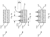
- Fig. 1A illustrates a cross-section of an exemplary sealing assembly 100 for sealing a bundle of wires.
- the sealing assembly 100 includes top and bottom layers 105a,105b or sheets formed from a sealant material.
- the middle layer 107 or sheet may include a thermally conductive material and a sealant material, which may be the same or different than the sealant material used for forming the top and bottom layers 105a, 105b.
- the thermally conductive material helps to promote more uniform and faster distribution of heat through the sealing assembly 100.
- the top, middle and bottom layers 105a, 107, and 105b may be formed from one of several sealant materials described below.
- the thickness of the top and bottom layers 105a, 105b may be between about 0.5-2mm.
- the thickness of the two layers 105a, 105b may be the same or different.
- the middle layer 107 may include a thermally conductive material embedded within the sealant material from which the middle layer is formed.
- the middle layer 107 may have a thickness of between about 0.2-2 mm, 0.1-2mm, 0.01-4mm, or a different thickness.
- the thermally conductive structure may correspond, for example, to a metal mesh or metal wool and may have a thickness of between about 0.05-0.4 mm or a different thickness. Other conductive structures may be utilized.
- the thermally conductive structure may correspond to a continuous structure that extends in the wrapping/longitudinal direction (205, Fig. 2A ) of the sealing assembly 100.
- the thermally conductive structure may have a thermal conductivity range of 50W/mK or higher.
- the thermally conductive structure may correspond to conductive material fragments that are sufficiently close to another to promote more uniform heat distribution.
- the wire from which the thermally conductive structure is formed may have a diameter of between about 0.02 and 0.4mm, and the mesh opening size may be between about 0.1-10mm.
- the wire may be formed from copper, aluminum, brass, bronze, steel-based materials, and/or alloys with high thermal conductivity. Other materials having similar thermal conductive characteristics may be utilized. For example, metal foils, formed metal foils, or perforated metal foils may be utilized as the thermally conductive structure.
- the thermally conductive structure may be coated with a thin electrically insulating material layer, which can provide electrical insulation while being thin enough not to affect the thermal conductivity or the ability to facilitate heat transfer during assembly.
- Sealant materials that may be utilized for forming the top, middle and bottom layers 105a, 107, and 105b generally correspond, to a hot melt thermoplastic sealant such as polyolefin based sealant (e.g., the base polymer is polyethylene (PE), metallocene-formed PE, maleic anhydride functionalized PE, or glycidyl methacrylate functionalized PE), polyolefin copolymer based sealant (e.g., the base polymer is ethylene-vinyl acetate copolymer (EVA)), a polyamide-based sealant, a thermoplastic elastomer (TPE) based sealant, a polyolefin and polyamide (PA) mixture based sealant, a polyolefin and polyolefin copolymer mixture based sealant (e.g., PE:EVA in weight ratios 95:5, 90:10, 75:25, or 50:50), a polyolefin copolymer and polyamide mixture
- a first sealant material for forming the top, middle and bottom layers 105a, 107, and 105b may be characterized by the following parameters: Viscosity (V) >1000 Pa s at ⁇ 100°C >300 Pa s (preferably >1000 Pa s) at ⁇ 105°C ⁇ 100 Pa s at ⁇ 110°C Softening temperature About 100 - 110°C Hardness, Shore D ⁇ 60 (preferably ⁇ 30)
- a second sealant material for forming the top, middle and bottom layers 105a, 107, and 105b may be characterized by the following parameters: Viscosity >1000 Pa s at ⁇ 100°C >300 Pa s (preferably >1000 Pa s) at ⁇ 120°C ⁇ 100 Pa s at ⁇ 125°C Softening temperature About 100 - 120°C Hardness, Shore D ⁇ 60 (preferably ⁇ 30
- the viscosity of the first and second sealant materials as well as the viscosity of the sealant materials described below was measured using a rotation rheometer.
- a small disk of sealant material e.g., 1.5mm-1.8mm thick, 25mm diameter disk
- sheared (oscillatory mode) by means of a rotational motion frequency of 6.28 rad/sec.
- the temperature of the sealant material is gradually increased from 60°C to 140°C at a rate of 5°C/min and the complex viscosity is measured as a function of temperature.
- the softening temperature referred to herein was the Ring and Ball softening temperature as measured according to ASTM E28.
- a third sealant material for forming the top, middle and bottom layers 105a, 107, and 105b may include a crosslinking agent to cause the sealant to undergo a change in viscosity characteristics when heated to a curing temperature.
- a crosslinking agent to cause the sealant to undergo a change in viscosity characteristics when heated to a curing temperature.
- an elevated temperature e.g., at or above the softening temperature
- the viscosity of the sealant increases. This results in a sealing assembly that can withstand higher temperatures, such as those temperatures that may be present in an automotive engine compartment.
- the third sealant material may include low molecular weight polymers (e.g., wax); a crosslinking agent (e.g., a peroxide, silanes), crosslinking promoting additives (co-agents, e.g., triallyl isocyanurate (TAIC), triallyl cyanurate (TAC), trimethylolpropane triacrylate (TMPTA), trimethylolpropane trimethacrylate (TMPTMA)), a polyolefin/polyamide/polyolefin copolymer (e.g., EVA) and other fillers or additives, such as carbon black, antioxidants, stabilizers, tackifiers, etc.
- a crosslinking agent e.g., a peroxide, silanes
- crosslinking promoting additives co-agents, e.g., triallyl isocyanurate (TAIC), triallyl cyanurate (TAC), trimethylolpropane tri
- the sealant may contain 50-90 weight % (wt%) base polymer, 0-43 wt% low molecular weight polymer, 2-8 wt% peroxide, 1-10 wt% co-agent, and 0-5 wt% of other additives.
- the resultant sealant may be characterized by the following parameters: Viscosity (V) ⁇ 1000 Pa ⁇ s at ⁇ 70°C ⁇ 100 Pa ⁇ s at 70°C ⁇ T ⁇ 110°C before curing >1000 Pa ⁇ s at ⁇ 110°C after curing >1000 Pa ⁇ s at ⁇ 110°C after curing Softening temperature About 60-80°C Hardness, Shore D ⁇ 60 (preferably ⁇ 30)
- a different sealant may be utilized for forming the middle layer 107.
- a fourth sealant which may be utilized to form the middle layer 107, may be characterized by the following parameters: Viscosity (V) >1000 Pa s at ⁇ 100°C >300 Pa s (preferably >1000 Pa s) at ⁇ 105°C ⁇ 100 Pa s at ⁇ 110°C Softening temperature About 105 - 120°C Hardness, Shore D ⁇ 60 (preferably ⁇ 30)
- the sealants may include filler materials to improve thermal conductivity without compromising the viscosity characteristics listed above.
- the filler materials may correspond to carbon, copper, nickel, aluminum, stainless steel, copper containing alloys, a copper-tin mixture, boron nitride, aluminum nitride, aluminum oxide, silicon carbide, beryllium oxide, silicon nitride, magnesium oxide, and/or other fillers
- the sealants may include stabilizer materials to improve longtime temperature aging characteristics.
- the sealant materials may have 0.2-2 wt% antioxidants (e.g., sterically hindered phenolic antioxidants) and/or secondary antioxidants (e.g., thioesters, lauryl/stearyl thiopropionate).
- Tackifiers may be added at 0.2-20 wt% to improve adhesion.
- physical or chemical foaming agents may be added to the sealants to improve the flow behavior and to reduce the sealant material usage.
- Fig. 1B illustrates a cross-section of a second exemplary sealing assembly 110 for sealing a bundle of wires.
- the second exemplary sealing assembly 110 corresponds to the first sealing assembly embodiment with the addition of teeth 108 or ridges formed on the top layer 105a.
- the teeth 108 may be formed with the sealant used for forming the top layer 105a.
- the conductive material in the middle layer 107 may extend through the top layer 105a and into the teeth 108.
- the teeth 108 help promote sealing between the wires by melting and flowing in between wires.
- the teeth 108 serve as guides that facilitate more uniform placement of wires on top of the assembly.
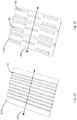
- the teeth 108 may run perpendicular to the wrapping/longitudinal direction 205 of the sealing assembly 110 as illustrated in Figs. 2A and 2B.
- Figs. 2A and 2B illustrate different exemplary patterns in which the teeth 108 may be arranged on the top layer 105a. As illustrated in Fig. 2A , the teeth 108 may extend from one edge of the assembly 110 to the opposite edge. As illustrated in Fig. 2B , some teeth may be shorter than other teeth. Other arrangements of the teeth 108 may be utilized as circumstances require.
- the teeth 108 may have a width, W1, of between about 0.25-5mm and a height, H, of between about 1-10mm.
- the teeth 108 may be spaced apart from one another by a distance, S, of between about 2-50mm.
- the shape of the teeth may vary. For example, as illustrated in Fig. 1C , the teeth may have a triangular shape in cross-section. However, the teeth may have a rectangular cross-section or a different cross-section.
- Fig. 1C illustrates a cross-section of a third exemplary sealing assembly 120 for sealing a bundle of wires.
- the third exemplary sealing assembly 120 corresponds to the second sealing assembly embodiment with the addition of a heat shrinkable material layer 109.
- the thickness of the heat-shrinkable material layer 109 may be between about 0.1-1mm.
- the heat-shrinkable material layer 109 may be formed from materials such as crosslinked polyolefin (e.g. polyethylene copolymer) or fluoropolymer (e.g.ethylene-tetrafluoroethylene copolymer (ETFE) or non-crosslinked materials (e.g., polyethylene terephthalate (PET)) with or without sealants (e.g. sealants in which the polymer base material is polyamide or a polyethylene copolymer such as ethylene-vinyl acetate copolymer (EVA)).
- sealants e.g. sealants in which the polymer base material is polyamide or a polyethylene copolymer such as ethylene-vinyl acetate copolymer (EVA)
- Commercial heat-shrink tapes may be utilized.
- the material from which the heat-shrinkable material layer 109 is formed may have a shrinkage of 5-50% between 105°C-150°C.
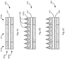
- Figs. 3A-3C help illustrate an exemplary methodology by which the third exemplary sealing assembly 120 may be utilized to seal a bundle of wires 305. It should be understood that the methodology may be applied to the other assemblies.
- the assembly 120 may be provided in a generally flat form. Wires 305 may then be placed upon the assembly 120. At this stage, the teeth 108 may act as guides to facilitate even distribution of the wires 305 over the top layer 105a of the assembly 120. For example, the number of wires 305 placed within the valleys defined between the teeth 108 may be selected so that the wires do not spill over into adjacent valleys. In addition, the teeth 108 help ensure that the wires cross over the assembly in a direction that is transverse to the direction in which the assembly will be wrapped or rolled.
- the assembly 120 and wires 305 may be rolled or wrapped in a longitudinal direction 205 within the assembly 120 so that the assembly 120 covers all the wires.
- the sealing assembly 120 and wires 305 may be spirally rolled in a spiral direction 205 so that the assembly 120 covers all the wires 305.
- Heat may then be applied to the spirally rolled sealing assembly and wires 300.
- the spirally rolled assembly and wires 300 may be heated in an oven, via a heat gun, and/or via some other heating system to a temperature of between about 105-160°C (as measured inside the assembly) for between about 1-10 minutes to obtain sealing.
- the thermally conductive material within the middle layer 107 helps to promote more uniform and faster distribution of heat energy throughout the spirally rolled assembly sealing assembly and wires 300 by conducting heat energy from the outer area of the spirally rolled assembly and wires 300 to the interior of the spirally rolled assembly and wires 300.
- the top and bottom layers 105a,105b of sealant material may melt together and fill voids between the wires 305 thereby sealing the wires 305.
- the heat-shrinkable material layer 109 forces the spirally rolled assembly and wires 300 to shrink in a radial direction. This in turn helps to squeeze the melted, or in some embodiments, softened sealant material into the voids.
- the assembly 120 may be folded into the shape illustrated in Fig. 3D or the shape illustrated in Fig. 3E .
- the wires 305 may then be placed within folds 320 of the folded assembly.
- the folded assembly may then be compressed so that the assembly is in tight contact with the wires and then heated to seal the bundle of wires.
- the assembly 120 may be folded into different shapes.
- the illustrated shape may be obtained by methods other than folding.
- the assembly 120 may be extruded from a die or be molded or overmolded from a mold, etc., and form a variety of shapes.
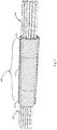
- Fig. 3F illustrates yet another embodiment of a sealing assembly 350 that may be utilized to seal a bundle of wires 305.
- the sealing assembly 350 may be formed using any of the sealants described herein via a molding technique such as extrusion from a die, molded or overmolded from a mold, etc.
- the sealing assembly 350 may define a comb-like structure.
- the sealing assembly 350 may include a lower portion 360 and a plurality of vertical members 355 or teeth extending from the lower portion 360 between which wires 305 may be inserted.
- the lower portion 360 may have a generally planar shape with a width, W1, of about 50mm-1000mm.
- a depth of the lower portion 360 i.e., the distance into the drawing and not shown
- the vertical members 355 may extend from the lower portion 360 to form a 90° angle with the lower portion 360, or may be at any other convenient angle for insertion of wires 305.
- the vertical members 355 may have a width, W2, of about 0.1-3mm, a height, H, of about 0.5-25mm, and may be spaced apart by a distance, L, of about 1-50mm.
- the vertical members 355 may be spaced evenly between first and second ends 370a,370b of the lower portion 360 or may be spaced differently.
- a conductive material 365 may be embedded in the lower portion 360 of the sealing assembly 350. While not illustrated, in other implementations, the conductive material may be embedded in the vertical members 355 as well.
- the conductive material 365 may correspond to any of the conductive materials described herein.
- the conductive material 365 may extend continuously between, for example, the first and second ends 370a,370b of the lower portion 360, as illustrated, or discontinuously.
- conductive material fragments that may or may not make direct contact with one another may be dispersed in the lower portion 360 or vertical members 355. In this regard, a distance between the conductive material fragments may be as much as 0.5mm.
- the conductive material 365 facilitates improved heat distribution throughout the assembly 350. This in turn facilitates improved softening or melting of the sealant from which the assembly 350 is formed.
- the wires 305 may be inserted between the vertical members 355.
- the assembly 350 and wires 305 may then be wrapped or rolled and then inserted within, for example, a heat shrinkable tube. Heat may then be applied to cause the sealant to soften or melt and the heat shrinkable tube to compress the sealant so that the sealant fills the voids between the wires 305.
- an article such as a heat-shrinkable article, an expanded rubber cover, a grommet or a different cover may be placed over the sealing assembly and wires prior to or during heating to apply constricting force to the sealing assembly and wires to promote flow of the sealant during heating.
- Fig. 4A illustrates a heat-shrinkable article 405 placed around the spirally rolled sealing assembly and wires 300 illustrated in Fig. 3B .
- Fig. 4B illustrates shrinkage of the heat-shrinkable article 405 around the spirally rolled sealing assembly and wires 300.
- the heat-shrinkable article 405 applies additional constricting force to the spirally rolled sealing assembly and wires 300 to help ensure that the sealant material flows into the voids.
- FIG. 4C illustrates the sealing assembly 120 when folded into the configuration illustrated in Fig. 3D , with a heat-shrinkable article 405 placed over the sealing assembly 120, and wires 305 inserted therein prior to heating.
- Fig. 4D illustrates shrinkage of the heat-shrinkable article 405 around the assembly 120 and wires 300.
- Heat recoverable (especially heat shrinkable) articles for example tubes, “boots”, “udders”, sleeves, wrap-around sheets, tapes and moldings.
- the heat-shrinkable article 405 may correspond to a commercial single or double layer heat-shrinkable sleeve tube such as RNF-100 or ATUM tubing sold by TE Connectivity Corporation.
- the heat-shrinkable article 405 may include sealants such as a polyamide sealant, EVA sealant, etc. Carbon, copper-tin, and/or other materials may be included to improve the thermal conductivity of the heat-shrinkable article 405.
- the wall thickness of the heat-shrinkable article 405 (or in the case of a heat-shrinkable tape, a thickness of the heat-shrinkable tape) before shrinking may be between about 0.5-2 mm.
- the heat-shrinkable article 405 may have a shrink ratio of 4:1, 3:1, 2:1, 1.5:1, or a different shrink ratio.
- the shrink temperature may be between about 80-150°C.
- Fig. 5 illustrates the assembly 300 or the assembly 400 with the heat-shrinkable sleeve 405 in final form.
- the wires 305 may extend from opposite ends of the assembly 300/400.
- the sealed assembly 300/400 may then be utilized for its intended application.
- the sealed assembly 300/400 facilitates running wires from the engine compartment through the firewall and into the cabin of the vehicle.
- the sealed assembly 300/400 may be snuggly fitted into an opening in the firewall, thereby preventing the ingress of water into the cabin of the vehicle from the engine compartment.
- the sealed assembly 300/400 may be inserted into a grommet and the grommet and sealed assembly 300/400 may be positioned within the opening.
- Figs. 6A-6C illustrate fourth, fifth, and sixth sealing assembly embodiments 600, 610, and 620 that respectively include the features of the first, second, and third embodiments 100, 110, and 120 presented in Figs. 1A-1C , respectively.
- the difference between the respective embodiments is that the sealant utilized for forming edge regions 612a,612b of the top and bottom layers 605a,605b of the fourth, fifth, and sixth sealing assembly embodiments 600, 610, and 620, is different from a sealant material used for forming the middle region 614.
- the sealant material or materials utilized in the middle region 614 may correspond to one or more of the first, second, third sealant materials for forming the top and bottom layers 105a,105b of the first, second, and third embodiments 100, 110, and 120, as described above.
- the sealant material for the edge regions 612a,612b may be selected to help slow or prevent, i.e. inhibit, the sealant in the middle region 614 from melting/pouring out of the assembly 600, 610, and 620 when heated.
- the sealant of the edge regions 612a,612b may have a thickness between about 0.5-2mm and be characterized by the following parameters: Viscosity (V) >1000 Pa s at ⁇ 100°C >300 Pa s (preferably >1000 Pa s) at ⁇ 105°C >500 Pa s (preferably >1000 Pa s) at ⁇ 110°C Softening temperature About 110 - 120°C Hardness, Shore D ⁇ 60 (preferably ⁇ 30)
- the sealant at the edge regions 612a, 612b may include filler and stabilizer materials to improve thermal conductivity without compromising the viscosity characteristics listed above and to improve longtime temperature aging characteristics, respectively.
- Fig. 7 illustrates the assembly embodiment 620 illustrated in Fig. 6C in final form.
- wires 305 may extend from opposite ends of the assembly 620.
- the sealed assembly 620 may then be utilized for its intended application such as facilitating running wires from an engine compartment through a firewall and into the cabin of a vehicle, as described above.
- a heat-shrinkable sleeve 805 or similar device that can apply a constricting force may be provided over the fourth, fifth, and sixth assembly embodiments 600, 610, and 620, as illustrated in Fig. 8 .
- the heat-shrinkable sleeve 805 helps to further squeeze the melted or softened sealant material into the voids between the wires 305.
- Fig. 9 illustrates an exemplary compression operation that may be applied to any of the assemblies described above to improve the sealing characteristics of the assembly. Illustrated are the assembly of Fig. 5 and a pair of compression plates 900a,900b that may correspond to parts of a press, where the plates 900a,900b may be pressed against the assembly prior to or just after applying heat to the assembly 300.
- the plates may define a generally cylindrical cavity 907 that defines the final/cured shape of the assembly. The amount of force is selected based on the viscosity of the sealant.
- the plates 900a,900b may include end regions 910a,900b that extend passed the sealing assembly 300 and over a portion of the wires extending from the sealing assembly 300.
- the diameter of the cylindrical cavity 905 at end regions 910a,900b may be reduced in comparison to the diameter of the center region 907 of the cylindrical cavity 907 to help prevent, i.e. inhibit, the sealant from spilling out through the ends of the assembly 300 during heating and compression.
- sealants having a viscosity of more than 20 Pa ⁇ s at a temperature of great than 100°C, which could effectively seal 100 wires or more with an applied pressure of about 1000kPa.
- sealants are less likely to spill out of the ends of the assembly.
- the sealants might not be capable of flowing between all the wires of the assembly without application of pressure.
- heat may be conveyed to the assembly via the compression plates 900a,900b. This may facilitate more uniform heating of the assembly 300.
- pressure is illustrated as being applied by a pair of plates 900a,900b, the pressure may be applied differently. For example, a different number of plates may be provided.
- a deflated bladder may be wrapped around the assembly, secured, and then inflated to compress the assembly 300.
- the plates may be urged together via resilient members (i.e., compression springs) that connect the plates together. Other methods may be utilized.
- the middle layer 107 may include a thermally conductive material to promote distribution of heat energy throughout the assembly.
- infrared (IR) heating or inductive heating may be utilized to heat the assembly.
- an IR absorbing material may be added to the sealant.
- 0.05-0.5 wt % carbon black may be added to the any of the sealants described above.
- the IR absorbing material converts the IR energy to heat, which in turn lowers the viscosity of the surrounding sealant, causing the sealant to fill in the voids between the wires.
- a heat-shrinkable sleeve 405 may be placed over the assembly 300 prior to heating the assembly, as illustrated in the assembly 400 of Figs. 4A and 4B .
- a transparent or semitransparent heat-shrinkable sleeve 405 may be utilized to allow the IR energy to passes through the heat-shrinkable sleeve 405 and to the IR absorbing material distributed throughout the assembly 400.
- the compression plates 900a,900b may be formed from a transparent or semitransparent material to facilitate passage of IR energy.
- a ferromagnetic material may be added to the sealant.
- nickel, nickel aluminum alloys, nickel chromium alloys, ferrites, and/or a different a ferromagnetic material may be added to any of the sealants described above.
- Generation of a relatively low power magnetic field e.g., ⁇ 10W may be sufficient to heat the sealant without damaging wire insulation.
- the conductive material may extend outside of the sealant to facilitate running electrical current through the conductive material. This in turn may result in resistance heating of the conductive material, which in turn will heat and therefore melt or soften the sealant material.
- the presence of a thermally conductive material may assist in the transfer of heat into the conductive material by means of conduction or convection.
Landscapes
- Engineering & Computer Science (AREA)
- Physics & Mathematics (AREA)
- Health & Medical Sciences (AREA)
- Manufacturing & Machinery (AREA)
- Thermal Sciences (AREA)
- Oral & Maxillofacial Surgery (AREA)
- Mechanical Engineering (AREA)
- Toxicology (AREA)
- Electromagnetism (AREA)
- Structural Engineering (AREA)
- Civil Engineering (AREA)
- Architecture (AREA)
- Sealing Material Composition (AREA)
- Gasket Seals (AREA)
- Insulated Conductors (AREA)
- Cable Accessories (AREA)
Claims (4)
- Integrierte Dichtungsanordnung (350) zum Abdichten eines Bündels von Drähten, die Folgendes umfasst:einen unteren Teil (360), der eine allgemein ebene Form definiert;mehrere vertikale Elemente (355), die sich vom unteren Teil (360) erstrecken und einen Raum dazwischen zum Platzieren von einem oder mehreren Drähten (305) in einer ersten Richtung aufweisen; undein wärmeleitendes Material (365), das im unteren Teil (360) eingebettet ist,wobei die integrierte Dichtungsanordnung (350) aus einem Dichtungsmaterial gebildet ist, undwobei, wenn ein oder mehrere Drähte (305) innerhalb des Raums zwischen den mehreren vertikalen Elementen (355) in der ersten Richtung angeordnet sind und die integrierte Dichtungsanordnung (350) in einer zweiten Richtung allgemein lotrecht zur ersten Richtung gewickelt ist, um dadurch die Drähte (305) zu umgeben, das wärmeleitende Material (365) der integrierten Dichtungsanordnung (350) die Wärmeenergieverteilung der aufgebrachten Wärme in der gesamten Anordnung (350) erleichtert, um dadurch eine Viskosität des Dichtungsmaterials bis zu einem Punkt zu senken, an dem das Dichtungsmaterial der integrierten Dichtungsanordnung (350) Hohlräume zwischen den ein oder mehreren Drähten (305) füllt.
- Integrierte Dichtungsanordnung (350) nach Anspruch 1, wobei das wärmeleitende Material (365) ferner in die vertikalen Elemente (355) eingebettet ist.
- Integrierte Dichtungsanordnung (350) nach Anspruch 1 oder Anspruch 2, wobei das Dichtungsmaterial eine Viskosität von weniger als 100 Pa·s oberhalb einer Temperatur von etwa 110°C und eine Viskosität von mehr als 1000 Pa·s bei einer Temperatur unter 100°C aufweist.
- Integrierte Dichtungsanordnung (350) nach einem der vorherigen Ansprüche, wobei die Dichtungsanordnung (305) ferner eine Abdeckung (405) umfasst, die zum Platzieren um die gewickelte Baugruppe (350) und das Bündel von Drähten (305) herum konfiguriert ist, wobei die Abdeckung das Fließen von Dichtungsmaterial in die Hohlräume zwischen den Drähten (305) fördert.
Priority Applications (1)
| Application Number | Priority Date | Filing Date | Title |
|---|---|---|---|
| EP21167173.0A EP3866289A1 (de) | 2016-09-30 | 2017-09-28 | Anordnung und verfahren zum abdichten eines drahtbündels |
Applications Claiming Priority (2)
| Application Number | Priority Date | Filing Date | Title |
|---|---|---|---|
| US15/282,670 US11239639B2 (en) | 2016-09-30 | 2016-09-30 | Assembly and method for sealing a bundle of wires |
| PCT/US2017/053971 WO2018064309A1 (en) | 2016-09-30 | 2017-09-28 | Assembly and method for sealing a bundle of wires |
Related Child Applications (1)
| Application Number | Title | Priority Date | Filing Date |
|---|---|---|---|
| EP21167173.0A Division EP3866289A1 (de) | 2016-09-30 | 2017-09-28 | Anordnung und verfahren zum abdichten eines drahtbündels |
Publications (2)
| Publication Number | Publication Date |
|---|---|
| EP3520190A1 EP3520190A1 (de) | 2019-08-07 |
| EP3520190B1 true EP3520190B1 (de) | 2021-04-21 |
Family
ID=60081313
Family Applications (2)
| Application Number | Title | Priority Date | Filing Date |
|---|---|---|---|
| EP17783672.3A Active EP3520190B1 (de) | 2016-09-30 | 2017-09-28 | Anordnung und verfahren zum abdichten eines drahtbündels |
| EP21167173.0A Pending EP3866289A1 (de) | 2016-09-30 | 2017-09-28 | Anordnung und verfahren zum abdichten eines drahtbündels |
Family Applications After (1)
| Application Number | Title | Priority Date | Filing Date |
|---|---|---|---|
| EP21167173.0A Pending EP3866289A1 (de) | 2016-09-30 | 2017-09-28 | Anordnung und verfahren zum abdichten eines drahtbündels |
Country Status (6)
| Country | Link |
|---|---|
| US (2) | US11239639B2 (de) |
| EP (2) | EP3520190B1 (de) |
| JP (1) | JP6865288B2 (de) |
| CN (1) | CN109792141A (de) |
| MX (1) | MX2019003632A (de) |
| WO (1) | WO2018064309A1 (de) |
Families Citing this family (9)
| Publication number | Priority date | Publication date | Assignee | Title |
|---|---|---|---|---|
| US11239639B2 (en) | 2016-09-30 | 2022-02-01 | TE Connectivity Services Gmbh | Assembly and method for sealing a bundle of wires |
| US10109947B2 (en) | 2017-02-07 | 2018-10-23 | Te Connectivity Corporation | System and method for sealing electrical terminals |
| US10103458B2 (en) | 2017-02-07 | 2018-10-16 | Te Connectivity Corporation | System and method for sealing electrical terminals |
| US10483661B2 (en) | 2017-02-07 | 2019-11-19 | Te Connectivity Corporation | System and method for sealing electrical terminals |
| JP6798438B2 (ja) | 2017-07-26 | 2020-12-09 | 株式会社オートネットワーク技術研究所 | 絶縁電線の製造方法および絶縁電線 |
| JP6525032B2 (ja) * | 2017-07-26 | 2019-06-05 | 株式会社オートネットワーク技術研究所 | 絶縁電線 |
| US10297946B1 (en) | 2018-04-19 | 2019-05-21 | Te Connectivity Corporation | Apparatus and methods for sealing electrical connections |
| US11257612B2 (en) * | 2018-07-26 | 2022-02-22 | TE Connectivity Services Gmbh | Assembly and method for sealing a bundle of wires |
| CN112248567B (zh) * | 2020-09-12 | 2022-06-21 | 杭州科能新材料科技有限公司 | 一种电缆绕包层用复合膜及其制备方法 |
Family Cites Families (55)
| Publication number | Priority date | Publication date | Assignee | Title |
|---|---|---|---|---|
| US3123663A (en) | 1964-03-03 | Insulated electrical connectors | ||
| US2932685A (en) | 1958-12-04 | 1960-04-12 | Burndy Corp | Cap for insulated electrical connector |
| BE754618A (fr) * | 1969-08-13 | 1971-02-10 | Cables De Lyon Geoffroy Delore | Procede de soudage, a ecran thermique thermoretractable, pour gaine de cable electrique |
| GB1599999A (en) | 1977-01-24 | 1981-10-14 | Raychem Ltd | Heat-recoverable articles |
| DE7930401U1 (de) * | 1979-09-11 | 1980-03-13 | N.V. Raychem S.A., Kessel-Lo (Belgien) | Kabelmuffeneinlage |
| JPS579210A (en) | 1980-05-12 | 1982-01-18 | Raychem Sa Nv | Method of producing connector, branch and terminal for cable |
| GB2075771B (en) | 1980-05-12 | 1984-11-28 | Raychem Sa Nv | Splicing branching or terminating cables |
| CA1165418A (en) | 1980-05-12 | 1984-04-10 | Marc F.L. Moisson | Splicing branching or terminating cables |
| DE3263612D1 (en) | 1981-01-30 | 1985-06-13 | Raychem Sa Nv | Re-enterable closure assembly |
| DE3129570C2 (de) * | 1981-07-27 | 1985-05-15 | Siemens AG, 1000 Berlin und 8000 München | Aufteilungsmuffe |
| US5140746A (en) | 1982-10-12 | 1992-08-25 | Raychem Corporation | Method and device for making electrical connector |
| US4993149A (en) | 1983-06-09 | 1991-02-19 | Ftz Industries, Inc. | Process for forming a termination on an electrical conductor |
| US4501927A (en) | 1983-08-31 | 1985-02-26 | Minnesota Mining And Manufacturing Company | Apparatus and method for sealing splices in insulated electrical cables |
| ES8607108A1 (es) | 1984-04-06 | 1986-06-01 | Raychem Sa Nv | Recubrimiento termorrecuperable y procedimiento para recu- brir un objeto de forma generalmente alargada |
| EP0159945B1 (de) | 1984-04-13 | 1991-01-02 | Raychem Pontoise S.A. | Vorrichtung zum Herstellen von Lötverbindungen |
| EP0188777B1 (de) | 1985-01-16 | 1989-03-15 | Walter Rose GmbH & Co. KG | Kabelmuffe mit einer querschnittlich kreuzförmigen Vorrichtung zum Stützen von in Kabelmuffen einlaufenden Kabelenden |
| GB8614369D0 (en) * | 1986-06-12 | 1986-07-16 | Raychem Ltd | Blocking arrangement |
| GB8626429D0 (en) | 1986-11-05 | 1986-12-03 | Raychem Sa Nv | Closure assembly |
| US4832248A (en) | 1986-11-20 | 1989-05-23 | Raychem Corporation | Adhesive and solder connection device |
| GB8710489D0 (en) | 1987-05-02 | 1987-06-03 | Raychem Pontoise Sa | Solder connector device |
| FR2627026A1 (fr) | 1988-02-08 | 1989-08-11 | Kerboul Michel | Procede pour realiser l'etancheite entre un cable ou element analogue et une conduite externe recevant ce cable et bande composite pour la mise en oeuvre de ce procede |
| DE58904891D1 (de) | 1988-03-18 | 1993-08-19 | Dsg Schrumpfschlauch Gmbh | Verfahren und vorrichtung zum laengswasserabdichten vieladriger kabelbuendel. |
| US4865920A (en) * | 1988-09-20 | 1989-09-12 | Dow Corning Corporation | Hot-melt pressure sensitive adhesive article and method of making |
| US5008340A (en) | 1988-12-21 | 1991-04-16 | Raychem Corporation | Curable adhesives |
| EP0489004B1 (de) | 1988-12-21 | 1995-10-25 | Raychem Corporation | Thermoplastischer fluorpolymer-klebstoff |
| GB8915614D0 (en) | 1989-07-07 | 1989-08-23 | Raychem Ltd | Environmental protection and bonding |
| DE3940698C1 (en) | 1989-12-08 | 1991-05-23 | Dsg Schrumpfschlauch Gmbh, 5309 Meckenheim, De | Water and gas proofing definite lengths of wiring - applying 2 layered tape having room temp. adhesive on side facing leads and heat-melting adhesive on outer layer |
| US5143122A (en) | 1990-09-11 | 1992-09-01 | Bundy Corporation | Composite flexible conduit assembly |
| JP2544850B2 (ja) | 1991-05-06 | 1996-10-16 | 住友電気工業株式会社 | 発泡性熱収縮チュ―ブの製造方法 |
| WO1992022105A1 (en) | 1991-06-06 | 1992-12-10 | Raychem S.A. | Arrangement for forming a sealed electrical splice |
| US5258578A (en) * | 1992-02-18 | 1993-11-02 | Minnesota Mining And Manufacturing Company | Closure end seal |
| US5378879A (en) * | 1993-04-20 | 1995-01-03 | Raychem Corporation | Induction heating of loaded materials |
| CA2132241C (en) | 1993-12-09 | 2000-11-28 | Ralph A. Martino | Semi-finished wood simulating product and method |
| GB9526120D0 (en) | 1995-12-21 | 1996-02-21 | Raychem Sa Nv | Electrical connector |
| US5922992A (en) | 1996-06-04 | 1999-07-13 | Kinney; D. Brooke | Electrical wire connector |
| US6024584A (en) | 1996-10-10 | 2000-02-15 | Berg Technology, Inc. | High density connector |
| US6139336A (en) | 1996-11-14 | 2000-10-31 | Berg Technology, Inc. | High density connector having a ball type of contact surface |
| JPH10329216A (ja) | 1997-05-28 | 1998-12-15 | Nkk Corp | 自己発熱型熱収縮チューブ |
| JPH11233175A (ja) | 1998-02-18 | 1999-08-27 | Sumitomo Wiring Syst Ltd | 電線端末の防水構造及び該防水構造の形成方法 |
| US6359226B1 (en) | 1998-04-21 | 2002-03-19 | Tyco Electronics Corporation | Device and method for protecting and sealing exposed wires |
| DE19923464C2 (de) | 1999-05-21 | 2002-04-25 | Siemens Ag | Abdichtvorrichtung für ein Leitungsbündel, Verfahren zum Abdichten eines Leitungsbündels und Verwendung der Abdichtvorrichtung |
| US6666732B1 (en) | 2001-05-21 | 2003-12-23 | John E. Endacott | Terminal connector |
| US6869292B2 (en) | 2001-07-31 | 2005-03-22 | Fci Americas Technology, Inc. | Modular mezzanine connector |
| GB0327000D0 (en) | 2003-11-20 | 2003-12-24 | Tyco Electronics Raychem Gmbh | Heat shrink jointing |
| US7230214B2 (en) | 2004-03-03 | 2007-06-12 | Tutco, Inc. | Metal sheathed heater using splice connection assembly with heat shrinkable tubing, and method of use |
| JP4433953B2 (ja) | 2004-09-09 | 2010-03-17 | 住友電装株式会社 | 端末スプライス部の防水処理方法および防水処理構造 |
| US7896712B2 (en) | 2005-12-22 | 2011-03-01 | Tensolite, Llc | Integral bonding attachment |
| TWI302767B (en) | 2006-03-24 | 2008-11-01 | Ks Terminals Inc | Terminal connector, manufacturing and wire connecting method thereof |
| US20110177727A1 (en) | 2010-01-18 | 2011-07-21 | Weiping Zhao | Aluminum conductor and conductive terminal connection |
| JP5880849B2 (ja) | 2012-05-15 | 2016-03-09 | 住友電装株式会社 | 圧着端子 |
| WO2014134330A1 (en) | 2013-02-27 | 2014-09-04 | Molex Incorporated | Compact connector system |
| DE112015003249T5 (de) | 2014-07-15 | 2017-04-13 | Sumitomo Electric Fine Polymer, Inc. | Wärmeschrumpfbares Rohr, wärmeschrumpfbarer Deckel und Verfahren zur Erzeugung einer Wasserresistenz bei einem elektrischen Drahtbündel |
| US10186794B2 (en) | 2015-09-25 | 2019-01-22 | Molex, Llc | Connector system with adapter |
| JP6613147B2 (ja) | 2016-01-14 | 2019-11-27 | 住友電気工業株式会社 | 熱回復部品、電線束、及び絶縁電線被覆方法 |
| US11239639B2 (en) | 2016-09-30 | 2022-02-01 | TE Connectivity Services Gmbh | Assembly and method for sealing a bundle of wires |
-
2016
- 2016-09-30 US US15/282,670 patent/US11239639B2/en active Active
-
2017
- 2017-09-28 EP EP17783672.3A patent/EP3520190B1/de active Active
- 2017-09-28 MX MX2019003632A patent/MX2019003632A/es unknown
- 2017-09-28 JP JP2019538104A patent/JP6865288B2/ja active Active
- 2017-09-28 EP EP21167173.0A patent/EP3866289A1/de active Pending
- 2017-09-28 CN CN201780059679.3A patent/CN109792141A/zh active Pending
- 2017-09-28 WO PCT/US2017/053971 patent/WO2018064309A1/en unknown
-
2021
- 2021-12-20 US US17/556,065 patent/US11843232B2/en active Active
Non-Patent Citations (1)
| Title |
|---|
| None * |
Also Published As
| Publication number | Publication date |
|---|---|
| JP2019532238A (ja) | 2019-11-07 |
| WO2018064309A1 (en) | 2018-04-05 |
| EP3520190A1 (de) | 2019-08-07 |
| EP3866289A1 (de) | 2021-08-18 |
| JP6865288B2 (ja) | 2021-04-28 |
| CN109792141A (zh) | 2019-05-21 |
| US11843232B2 (en) | 2023-12-12 |
| MX2019003632A (es) | 2019-06-17 |
| US20180097344A1 (en) | 2018-04-05 |
| US11239639B2 (en) | 2022-02-01 |
| US20220115848A1 (en) | 2022-04-14 |
Similar Documents
| Publication | Publication Date | Title |
|---|---|---|
| EP3520190B1 (de) | Anordnung und verfahren zum abdichten eines drahtbündels | |
| US3435401A (en) | Insulated electrical conductors | |
| US3834458A (en) | Pipe heat transfer assembly and method of making same | |
| GB2197419A (en) | Conduit with heater strip | |
| WO2014095563A1 (en) | Multi-layer heat-shrinkable tubular sleeve with stress control elements | |
| EP2963654B1 (de) | Feldabstufungsschicht | |
| JP6816299B2 (ja) | 電気端子を封止するためのシステムおよび方法 | |
| JP7425144B2 (ja) | 封止されたワイヤ束を作り出すための構造物 | |
| US761204A (en) | Method of making electrical heating apparatus. | |
| CN102231497A (zh) | 一种高压柔性直流挤出绝缘电缆模塑型接头装置 | |
| JP4084183B2 (ja) | ポリマー碍子の製造方法 | |
| JP5461220B2 (ja) | 面状ヒータの製造方法及び面状ヒータ | |
| EP2966334B1 (de) | Beheiztes Leitungsrohr für Flüssigkeitszuführungssystem in einem Kraftfahrzeug | |
| KR101260070B1 (ko) | 전기적 성능을 갖는 적층구조의 탄성체 튜브 및 그 제조방법 | |
| JP3012515B2 (ja) | Cvケーブルの絶縁接続方法 | |
| JPH046149Y2 (de) | ||
| JPS5859030A (ja) | ゴム・プラスチツク絶縁ケ−ブル接続部の形成方法 | |
| JPS6215985Y2 (de) | ||
| JPH0132311Y2 (de) | ||
| WO2015045837A1 (ja) | 絶縁被覆電線及びその製造方法 | |
| JPH0142582B2 (de) | ||
| JPH09247817A (ja) | Cvケーブルの絶縁接続方法 | |
| IE43758B1 (en) | Heat-recoverable articles and methods for their application | |
| JPS6364276A (ja) | プラスチツク絶縁ケ−ブル接続部の成形方法 |
Legal Events
| Date | Code | Title | Description |
|---|---|---|---|
| STAA | Information on the status of an ep patent application or granted ep patent |
Free format text: STATUS: UNKNOWN |
|
| STAA | Information on the status of an ep patent application or granted ep patent |
Free format text: STATUS: THE INTERNATIONAL PUBLICATION HAS BEEN MADE |
|
| PUAI | Public reference made under article 153(3) epc to a published international application that has entered the european phase |
Free format text: ORIGINAL CODE: 0009012 |
|
| STAA | Information on the status of an ep patent application or granted ep patent |
Free format text: STATUS: REQUEST FOR EXAMINATION WAS MADE |
|
| 17P | Request for examination filed |
Effective date: 20190423 |
|
| AK | Designated contracting states |
Kind code of ref document: A1 Designated state(s): AL AT BE BG CH CY CZ DE DK EE ES FI FR GB GR HR HU IE IS IT LI LT LU LV MC MK MT NL NO PL PT RO RS SE SI SK SM TR |
|
| AX | Request for extension of the european patent |
Extension state: BA ME |
|
| DAV | Request for validation of the european patent (deleted) | ||
| DAX | Request for extension of the european patent (deleted) | ||
| STAA | Information on the status of an ep patent application or granted ep patent |
Free format text: STATUS: EXAMINATION IS IN PROGRESS |
|
| 17Q | First examination report despatched |
Effective date: 20200203 |
|
| GRAP | Despatch of communication of intention to grant a patent |
Free format text: ORIGINAL CODE: EPIDOSNIGR1 |
|
| STAA | Information on the status of an ep patent application or granted ep patent |
Free format text: STATUS: GRANT OF PATENT IS INTENDED |
|
| INTG | Intention to grant announced |
Effective date: 20201201 |
|
| GRAS | Grant fee paid |
Free format text: ORIGINAL CODE: EPIDOSNIGR3 |
|
| GRAA | (expected) grant |
Free format text: ORIGINAL CODE: 0009210 |
|
| STAA | Information on the status of an ep patent application or granted ep patent |
Free format text: STATUS: THE PATENT HAS BEEN GRANTED |
|
| AK | Designated contracting states |
Kind code of ref document: B1 Designated state(s): AL AT BE BG CH CY CZ DE DK EE ES FI FR GB GR HR HU IE IS IT LI LT LU LV MC MK MT NL NO PL PT RO RS SE SI SK SM TR |
|
| REG | Reference to a national code |
Ref country code: GB Ref legal event code: FG4D |
|
| REG | Reference to a national code |
Ref country code: CH Ref legal event code: EP |
|
| REG | Reference to a national code |
Ref country code: DE Ref legal event code: R096 Ref document number: 602017037190 Country of ref document: DE Ref country code: IE Ref legal event code: FG4D |
|
| REG | Reference to a national code |
Ref country code: AT Ref legal event code: REF Ref document number: 1385645 Country of ref document: AT Kind code of ref document: T Effective date: 20210515 |
|
| REG | Reference to a national code |
Ref country code: LT Ref legal event code: MG9D |
|
| REG | Reference to a national code |
Ref country code: AT Ref legal event code: MK05 Ref document number: 1385645 Country of ref document: AT Kind code of ref document: T Effective date: 20210421 |
|
| REG | Reference to a national code |
Ref country code: NL Ref legal event code: MP Effective date: 20210421 |
|
| PG25 | Lapsed in a contracting state [announced via postgrant information from national office to epo] |
Ref country code: HR Free format text: LAPSE BECAUSE OF FAILURE TO SUBMIT A TRANSLATION OF THE DESCRIPTION OR TO PAY THE FEE WITHIN THE PRESCRIBED TIME-LIMIT Effective date: 20210421 Ref country code: BG Free format text: LAPSE BECAUSE OF FAILURE TO SUBMIT A TRANSLATION OF THE DESCRIPTION OR TO PAY THE FEE WITHIN THE PRESCRIBED TIME-LIMIT Effective date: 20210721 Ref country code: AT Free format text: LAPSE BECAUSE OF FAILURE TO SUBMIT A TRANSLATION OF THE DESCRIPTION OR TO PAY THE FEE WITHIN THE PRESCRIBED TIME-LIMIT Effective date: 20210421 Ref country code: NL Free format text: LAPSE BECAUSE OF FAILURE TO SUBMIT A TRANSLATION OF THE DESCRIPTION OR TO PAY THE FEE WITHIN THE PRESCRIBED TIME-LIMIT Effective date: 20210421 Ref country code: FI Free format text: LAPSE BECAUSE OF FAILURE TO SUBMIT A TRANSLATION OF THE DESCRIPTION OR TO PAY THE FEE WITHIN THE PRESCRIBED TIME-LIMIT Effective date: 20210421 Ref country code: LT Free format text: LAPSE BECAUSE OF FAILURE TO SUBMIT A TRANSLATION OF THE DESCRIPTION OR TO PAY THE FEE WITHIN THE PRESCRIBED TIME-LIMIT Effective date: 20210421 |
|
| PG25 | Lapsed in a contracting state [announced via postgrant information from national office to epo] |
Ref country code: SE Free format text: LAPSE BECAUSE OF FAILURE TO SUBMIT A TRANSLATION OF THE DESCRIPTION OR TO PAY THE FEE WITHIN THE PRESCRIBED TIME-LIMIT Effective date: 20210421 Ref country code: RS Free format text: LAPSE BECAUSE OF FAILURE TO SUBMIT A TRANSLATION OF THE DESCRIPTION OR TO PAY THE FEE WITHIN THE PRESCRIBED TIME-LIMIT Effective date: 20210421 Ref country code: PL Free format text: LAPSE BECAUSE OF FAILURE TO SUBMIT A TRANSLATION OF THE DESCRIPTION OR TO PAY THE FEE WITHIN THE PRESCRIBED TIME-LIMIT Effective date: 20210421 Ref country code: NO Free format text: LAPSE BECAUSE OF FAILURE TO SUBMIT A TRANSLATION OF THE DESCRIPTION OR TO PAY THE FEE WITHIN THE PRESCRIBED TIME-LIMIT Effective date: 20210721 Ref country code: LV Free format text: LAPSE BECAUSE OF FAILURE TO SUBMIT A TRANSLATION OF THE DESCRIPTION OR TO PAY THE FEE WITHIN THE PRESCRIBED TIME-LIMIT Effective date: 20210421 Ref country code: PT Free format text: LAPSE BECAUSE OF FAILURE TO SUBMIT A TRANSLATION OF THE DESCRIPTION OR TO PAY THE FEE WITHIN THE PRESCRIBED TIME-LIMIT Effective date: 20210823 Ref country code: GR Free format text: LAPSE BECAUSE OF FAILURE TO SUBMIT A TRANSLATION OF THE DESCRIPTION OR TO PAY THE FEE WITHIN THE PRESCRIBED TIME-LIMIT Effective date: 20210722 Ref country code: IS Free format text: LAPSE BECAUSE OF FAILURE TO SUBMIT A TRANSLATION OF THE DESCRIPTION OR TO PAY THE FEE WITHIN THE PRESCRIBED TIME-LIMIT Effective date: 20210821 |
|
| REG | Reference to a national code |
Ref country code: DE Ref legal event code: R097 Ref document number: 602017037190 Country of ref document: DE |
|
| PG25 | Lapsed in a contracting state [announced via postgrant information from national office to epo] |
Ref country code: SM Free format text: LAPSE BECAUSE OF FAILURE TO SUBMIT A TRANSLATION OF THE DESCRIPTION OR TO PAY THE FEE WITHIN THE PRESCRIBED TIME-LIMIT Effective date: 20210421 Ref country code: SK Free format text: LAPSE BECAUSE OF FAILURE TO SUBMIT A TRANSLATION OF THE DESCRIPTION OR TO PAY THE FEE WITHIN THE PRESCRIBED TIME-LIMIT Effective date: 20210421 Ref country code: EE Free format text: LAPSE BECAUSE OF FAILURE TO SUBMIT A TRANSLATION OF THE DESCRIPTION OR TO PAY THE FEE WITHIN THE PRESCRIBED TIME-LIMIT Effective date: 20210421 Ref country code: CZ Free format text: LAPSE BECAUSE OF FAILURE TO SUBMIT A TRANSLATION OF THE DESCRIPTION OR TO PAY THE FEE WITHIN THE PRESCRIBED TIME-LIMIT Effective date: 20210421 Ref country code: DK Free format text: LAPSE BECAUSE OF FAILURE TO SUBMIT A TRANSLATION OF THE DESCRIPTION OR TO PAY THE FEE WITHIN THE PRESCRIBED TIME-LIMIT Effective date: 20210421 Ref country code: RO Free format text: LAPSE BECAUSE OF FAILURE TO SUBMIT A TRANSLATION OF THE DESCRIPTION OR TO PAY THE FEE WITHIN THE PRESCRIBED TIME-LIMIT Effective date: 20210421 Ref country code: ES Free format text: LAPSE BECAUSE OF FAILURE TO SUBMIT A TRANSLATION OF THE DESCRIPTION OR TO PAY THE FEE WITHIN THE PRESCRIBED TIME-LIMIT Effective date: 20210421 |
|
| PLBE | No opposition filed within time limit |
Free format text: ORIGINAL CODE: 0009261 |
|
| STAA | Information on the status of an ep patent application or granted ep patent |
Free format text: STATUS: NO OPPOSITION FILED WITHIN TIME LIMIT |
|
| 26N | No opposition filed |
Effective date: 20220124 |
|
| REG | Reference to a national code |
Ref country code: CH Ref legal event code: PL |
|
| REG | Reference to a national code |
Ref country code: BE Ref legal event code: MM Effective date: 20210930 |
|
| GBPC | Gb: european patent ceased through non-payment of renewal fee |
Effective date: 20210928 |
|
| PG25 | Lapsed in a contracting state [announced via postgrant information from national office to epo] |
Ref country code: IS Free format text: LAPSE BECAUSE OF FAILURE TO SUBMIT A TRANSLATION OF THE DESCRIPTION OR TO PAY THE FEE WITHIN THE PRESCRIBED TIME-LIMIT Effective date: 20210821 Ref country code: MC Free format text: LAPSE BECAUSE OF FAILURE TO SUBMIT A TRANSLATION OF THE DESCRIPTION OR TO PAY THE FEE WITHIN THE PRESCRIBED TIME-LIMIT Effective date: 20210421 Ref country code: AL Free format text: LAPSE BECAUSE OF FAILURE TO SUBMIT A TRANSLATION OF THE DESCRIPTION OR TO PAY THE FEE WITHIN THE PRESCRIBED TIME-LIMIT Effective date: 20210421 |
|
| PG25 | Lapsed in a contracting state [announced via postgrant information from national office to epo] |
Ref country code: LU Free format text: LAPSE BECAUSE OF NON-PAYMENT OF DUE FEES Effective date: 20210928 Ref country code: IT Free format text: LAPSE BECAUSE OF FAILURE TO SUBMIT A TRANSLATION OF THE DESCRIPTION OR TO PAY THE FEE WITHIN THE PRESCRIBED TIME-LIMIT Effective date: 20210421 Ref country code: IE Free format text: LAPSE BECAUSE OF NON-PAYMENT OF DUE FEES Effective date: 20210928 Ref country code: GB Free format text: LAPSE BECAUSE OF NON-PAYMENT OF DUE FEES Effective date: 20210928 Ref country code: FR Free format text: LAPSE BECAUSE OF NON-PAYMENT OF DUE FEES Effective date: 20210930 Ref country code: BE Free format text: LAPSE BECAUSE OF NON-PAYMENT OF DUE FEES Effective date: 20210930 |
|
| PG25 | Lapsed in a contracting state [announced via postgrant information from national office to epo] |
Ref country code: LI Free format text: LAPSE BECAUSE OF NON-PAYMENT OF DUE FEES Effective date: 20210930 Ref country code: CH Free format text: LAPSE BECAUSE OF NON-PAYMENT OF DUE FEES Effective date: 20210930 |
|
| PG25 | Lapsed in a contracting state [announced via postgrant information from national office to epo] |
Ref country code: CY Free format text: LAPSE BECAUSE OF FAILURE TO SUBMIT A TRANSLATION OF THE DESCRIPTION OR TO PAY THE FEE WITHIN THE PRESCRIBED TIME-LIMIT Effective date: 20210421 |
|
| PG25 | Lapsed in a contracting state [announced via postgrant information from national office to epo] |
Ref country code: HU Free format text: LAPSE BECAUSE OF FAILURE TO SUBMIT A TRANSLATION OF THE DESCRIPTION OR TO PAY THE FEE WITHIN THE PRESCRIBED TIME-LIMIT; INVALID AB INITIO Effective date: 20170928 |
|
| PGFP | Annual fee paid to national office [announced via postgrant information from national office to epo] |
Ref country code: DE Payment date: 20230802 Year of fee payment: 7 |
|
| PG25 | Lapsed in a contracting state [announced via postgrant information from national office to epo] |
Ref country code: MK Free format text: LAPSE BECAUSE OF FAILURE TO SUBMIT A TRANSLATION OF THE DESCRIPTION OR TO PAY THE FEE WITHIN THE PRESCRIBED TIME-LIMIT Effective date: 20210421 |