EP3518015B1 - Kameramodul und optische vorrichtung - Google Patents
Kameramodul und optische vorrichtung Download PDFInfo
- Publication number
- EP3518015B1 EP3518015B1 EP17853484.8A EP17853484A EP3518015B1 EP 3518015 B1 EP3518015 B1 EP 3518015B1 EP 17853484 A EP17853484 A EP 17853484A EP 3518015 B1 EP3518015 B1 EP 3518015B1
- Authority
- EP
- European Patent Office
- Prior art keywords
- diaphragm
- disposed
- substrate
- camera module
- lens
- Prior art date
- Legal status (The legal status is an assumption and is not a legal conclusion. Google has not performed a legal analysis and makes no representation as to the accuracy of the status listed.)
- Active
Links
Images



Classifications
-
- G—PHYSICS
- G02—OPTICS
- G02B—OPTICAL ELEMENTS, SYSTEMS OR APPARATUS
- G02B27/00—Optical systems or apparatus not provided for by any of the groups G02B1/00 - G02B26/00, G02B30/00
- G02B27/64—Imaging systems using optical elements for stabilisation of the lateral and angular position of the image
- G02B27/646—Imaging systems using optical elements for stabilisation of the lateral and angular position of the image compensating for small deviations, e.g. due to vibration or shake
-
- G—PHYSICS
- G02—OPTICS
- G02B—OPTICAL ELEMENTS, SYSTEMS OR APPARATUS
- G02B5/00—Optical elements other than lenses
- G02B5/20—Filters
- G02B5/208—Filters for use with infrared or ultraviolet radiation, e.g. for separating visible light from infrared and/or ultraviolet radiation
-
- G—PHYSICS
- G02—OPTICS
- G02B—OPTICAL ELEMENTS, SYSTEMS OR APPARATUS
- G02B7/00—Mountings, adjusting means, or light-tight connections, for optical elements
- G02B7/003—Alignment of optical elements
- G02B7/005—Motorised alignment
-
- G—PHYSICS
- G02—OPTICS
- G02B—OPTICAL ELEMENTS, SYSTEMS OR APPARATUS
- G02B7/00—Mountings, adjusting means, or light-tight connections, for optical elements
- G02B7/02—Mountings, adjusting means, or light-tight connections, for optical elements for lenses
-
- G—PHYSICS
- G02—OPTICS
- G02B—OPTICAL ELEMENTS, SYSTEMS OR APPARATUS
- G02B7/00—Mountings, adjusting means, or light-tight connections, for optical elements
- G02B7/02—Mountings, adjusting means, or light-tight connections, for optical elements for lenses
- G02B7/021—Mountings, adjusting means, or light-tight connections, for optical elements for lenses for more than one lens
-
- G—PHYSICS
- G02—OPTICS
- G02B—OPTICAL ELEMENTS, SYSTEMS OR APPARATUS
- G02B7/00—Mountings, adjusting means, or light-tight connections, for optical elements
- G02B7/02—Mountings, adjusting means, or light-tight connections, for optical elements for lenses
- G02B7/023—Mountings, adjusting means, or light-tight connections, for optical elements for lenses permitting adjustment
-
- G—PHYSICS
- G03—PHOTOGRAPHY; CINEMATOGRAPHY; ANALOGOUS TECHNIQUES USING WAVES OTHER THAN OPTICAL WAVES; ELECTROGRAPHY; HOLOGRAPHY
- G03B—APPARATUS OR ARRANGEMENTS FOR TAKING PHOTOGRAPHS OR FOR PROJECTING OR VIEWING THEM; APPARATUS OR ARRANGEMENTS EMPLOYING ANALOGOUS TECHNIQUES USING WAVES OTHER THAN OPTICAL WAVES; ACCESSORIES THEREFOR
- G03B11/00—Filters or other obturators specially adapted for photographic purposes
-
- G—PHYSICS
- G03—PHOTOGRAPHY; CINEMATOGRAPHY; ANALOGOUS TECHNIQUES USING WAVES OTHER THAN OPTICAL WAVES; ELECTROGRAPHY; HOLOGRAPHY
- G03B—APPARATUS OR ARRANGEMENTS FOR TAKING PHOTOGRAPHS OR FOR PROJECTING OR VIEWING THEM; APPARATUS OR ARRANGEMENTS EMPLOYING ANALOGOUS TECHNIQUES USING WAVES OTHER THAN OPTICAL WAVES; ACCESSORIES THEREFOR
- G03B30/00—Camera modules comprising integrated lens units and imaging units, specially adapted for being embedded in other devices, e.g. mobile phones or vehicles
-
- G—PHYSICS
- G03—PHOTOGRAPHY; CINEMATOGRAPHY; ANALOGOUS TECHNIQUES USING WAVES OTHER THAN OPTICAL WAVES; ELECTROGRAPHY; HOLOGRAPHY
- G03B—APPARATUS OR ARRANGEMENTS FOR TAKING PHOTOGRAPHS OR FOR PROJECTING OR VIEWING THEM; APPARATUS OR ARRANGEMENTS EMPLOYING ANALOGOUS TECHNIQUES USING WAVES OTHER THAN OPTICAL WAVES; ACCESSORIES THEREFOR
- G03B9/00—Exposure-making shutters; Diaphragms
- G03B9/02—Diaphragms
-
- G—PHYSICS
- G03—PHOTOGRAPHY; CINEMATOGRAPHY; ANALOGOUS TECHNIQUES USING WAVES OTHER THAN OPTICAL WAVES; ELECTROGRAPHY; HOLOGRAPHY
- G03B—APPARATUS OR ARRANGEMENTS FOR TAKING PHOTOGRAPHS OR FOR PROJECTING OR VIEWING THEM; APPARATUS OR ARRANGEMENTS EMPLOYING ANALOGOUS TECHNIQUES USING WAVES OTHER THAN OPTICAL WAVES; ACCESSORIES THEREFOR
- G03B9/00—Exposure-making shutters; Diaphragms
- G03B9/02—Diaphragms
- G03B9/04—Single movable plate with two or more apertures of graded size, e.g. sliding plate or pivoting plate
-
- G—PHYSICS
- G03—PHOTOGRAPHY; CINEMATOGRAPHY; ANALOGOUS TECHNIQUES USING WAVES OTHER THAN OPTICAL WAVES; ELECTROGRAPHY; HOLOGRAPHY
- G03B—APPARATUS OR ARRANGEMENTS FOR TAKING PHOTOGRAPHS OR FOR PROJECTING OR VIEWING THEM; APPARATUS OR ARRANGEMENTS EMPLOYING ANALOGOUS TECHNIQUES USING WAVES OTHER THAN OPTICAL WAVES; ACCESSORIES THEREFOR
- G03B9/00—Exposure-making shutters; Diaphragms
- G03B9/08—Shutters
-
- H—ELECTRICITY
- H04—ELECTRIC COMMUNICATION TECHNIQUE
- H04N—PICTORIAL COMMUNICATION, e.g. TELEVISION
- H04N23/00—Cameras or camera modules comprising electronic image sensors; Control thereof
-
- H—ELECTRICITY
- H04—ELECTRIC COMMUNICATION TECHNIQUE
- H04N—PICTORIAL COMMUNICATION, e.g. TELEVISION
- H04N23/00—Cameras or camera modules comprising electronic image sensors; Control thereof
- H04N23/50—Constructional details
- H04N23/51—Housings
-
- H—ELECTRICITY
- H04—ELECTRIC COMMUNICATION TECHNIQUE
- H04N—PICTORIAL COMMUNICATION, e.g. TELEVISION
- H04N23/00—Cameras or camera modules comprising electronic image sensors; Control thereof
- H04N23/50—Constructional details
- H04N23/54—Mounting of pick-up tubes, electronic image sensors, deviation or focusing coils
-
- H—ELECTRICITY
- H04—ELECTRIC COMMUNICATION TECHNIQUE
- H04N—PICTORIAL COMMUNICATION, e.g. TELEVISION
- H04N23/00—Cameras or camera modules comprising electronic image sensors; Control thereof
- H04N23/50—Constructional details
- H04N23/55—Optical parts specially adapted for electronic image sensors; Mounting thereof
-
- H—ELECTRICITY
- H04—ELECTRIC COMMUNICATION TECHNIQUE
- H04N—PICTORIAL COMMUNICATION, e.g. TELEVISION
- H04N23/00—Cameras or camera modules comprising electronic image sensors; Control thereof
- H04N23/57—Mechanical or electrical details of cameras or camera modules specially adapted for being embedded in other devices
-
- H—ELECTRICITY
- H04—ELECTRIC COMMUNICATION TECHNIQUE
- H04N—PICTORIAL COMMUNICATION, e.g. TELEVISION
- H04N23/00—Cameras or camera modules comprising electronic image sensors; Control thereof
- H04N23/60—Control of cameras or camera modules
-
- H—ELECTRICITY
- H04—ELECTRIC COMMUNICATION TECHNIQUE
- H04N—PICTORIAL COMMUNICATION, e.g. TELEVISION
- H04N25/00—Circuitry of solid-state image sensors [SSIS]; Control thereof
-
- G—PHYSICS
- G03—PHOTOGRAPHY; CINEMATOGRAPHY; ANALOGOUS TECHNIQUES USING WAVES OTHER THAN OPTICAL WAVES; ELECTROGRAPHY; HOLOGRAPHY
- G03B—APPARATUS OR ARRANGEMENTS FOR TAKING PHOTOGRAPHS OR FOR PROJECTING OR VIEWING THEM; APPARATUS OR ARRANGEMENTS EMPLOYING ANALOGOUS TECHNIQUES USING WAVES OTHER THAN OPTICAL WAVES; ACCESSORIES THEREFOR
- G03B2205/00—Adjustment of optical system relative to image or object surface other than for focusing
- G03B2205/0053—Driving means for the movement of one or more optical element
- G03B2205/0069—Driving means for the movement of one or more optical element using electromagnetic actuators, e.g. voice coils
-
- H—ELECTRICITY
- H02—GENERATION; CONVERSION OR DISTRIBUTION OF ELECTRIC POWER
- H02K—DYNAMO-ELECTRIC MACHINES
- H02K41/00—Propulsion systems in which a rigid body is moved along a path due to dynamo-electric interaction between the body and a magnetic field travelling along the path
- H02K41/02—Linear motors; Sectional motors
- H02K41/035—DC motors; Unipolar motors
- H02K41/0352—Unipolar motors
- H02K41/0354—Lorentz force motors, e.g. voice coil motors
Definitions
- the present exemplary embodiment relates to a camera lens barrel, camera module, and an optical device.
- AF auto focus
- OIS optical image stabilization
- the diaphragm adjusts the degree of opening of the lens by a separate actuator, and is usually located between the front lens and the rear lens among the lens groups of the camera module, therefore the electrical connection with the main board is continuously maintained with the mobility along the optical axis.
- a separate actuator is usually located between the front lens and the rear lens among the lens groups of the camera module, therefore the electrical connection with the main board is continuously maintained with the mobility along the optical axis.
- An objective of the present invention conceived to overcome the above problems, is to provide a camera module and an optical device that are easy to manufacture since the electrical connection between a main control device and a diaphragm device included in a lens barrel is convenient
- Another objective of the present invention conceived to overcome the above problems, is to provide a camera lens barrel wherein the combining of the diaphragm between the front lens and the rear lens is easy, and also the assembling of the lenses can be performed conveniently.
- a further embodiment according to the present invention concerns an optical device comprising: a main body; a display unit disposed at one side surface of the main body; and a camera module as claimed electrically connected to the display unit.
- a camera module and an optical device provide an effect in that the terminals connected to the outside are minimized by disposing a control unit integrally formed with a sensor for detecting the degree of opening of the diaphragm in the diaphragm part, and also common terminals are implemented to be used for both of the terminals for driving the auto focusing device and the terminals for driving the diaphragm, and are selectively driven so that the sharing and simplifying the wirings can be achieved, thereby reducing the manufacturing cost of the camera module and the optical device.
- optical axis direction used below is defined as the optical axis direction of the lens module in a state of being coupled to the lens driving device.
- optical axis direction can be used in combination with “vertical direction,” “z-axis,” and the like.
- the "camera shake correction function” used below is defined as a function of moving or tilting the lens module in the direction perpendicular to the optical axis direction so as to cancel the vibration (motion) generated in the image sensor by an external force.
- “camera shake correction” can be used in combination with “optical image stabilization (OIS)”.
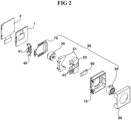
- a housing 10 formed with a space therein is disposed at front side with respect to the base 1, and a first substrate 2 is disposed at rear side.
- the housing 10 may have a rectangular box shape, or may be changed to another shape if necessary, and a space for accommodating other members therein is formed, and an opening portion 11 is formed at a side surface thereof.
- a lens set 90 is disposed in the inner space of the housing 10 and the lens set 90 is movable along the front-to-rear direction for autofocusing within the housing 10.
- first magnet fixed to the lens set 90 a first coil corresponding to the first magnet provided on the side of the housing 10
- a first driving unit comprising a first Hall sensor which recognizes the position of the lens set 90.
- a guide ball or the like having a low friction characteristic is disposed between the lens set 90 and the housing 10.
- the lens set 90 is transported along the up-down direction within the housing 10 by the first drive unit.
- the lens set 90 is disposed with a first lens barrel unit 20 at front thereof, a diaphragm set 50 at the rear side of the first lens barrel unit 20, and a second lens barrel unit 30 at the rear side of the diaphragm set 50, respectively.
- the diaphragm set 50 is constructed first with a diaphragm support unit 51.
- the diaphragm support unit 51 is seated on the inner surface of the housing 10 and can move along the front-to-rear direction within the housing 10 and serves as a structure for supporting the entire diaphragm set 50.
- a first magnet which is a component of the first drive unit, is fixed.
- it may be configured to be a type wherein a plurality of members are mutually coupled, and a receiving part 52 is formed at the center so that a diaphragm part 60 can be seated therein.
- the diaphragm part 60 is coupled to the receiving part 52 and a guide portion 53 is formed to facilitate the coupling of the diaphragm part 60.
- the guide portion 53 is configured such that the diaphragm part 60 is inserted therein and guided thereby. However, if necessary, the guide portion 53 may be implemented using a projection or the like.
- first lens coupling portion and the second lens coupling portion may be formed of a conventional coupling structure such as a protrusion, a step portion, or the like which can be simply coupled with the first lens barrel unit 20 and the second lens barrel unit 30.
- the diaphragm set 50 comprises a diaphragm part 60 shown in Fig. 4 , and the diaphragm part 60 is configured to comprise a body portion 61 formed with a hole 62 whose center coincides with the optical axis of the lens of the first lens barrel unit 20.
- an adjustment portion 63 comprising a blade unit (not shown) for adjusting the degree of opening of the hole 62 and a second drive unit comprising a second magnet and a second coil for coupling with the blade unit for operating thereof, and comprises a second Hall sensor 64 for recognizing the operation position of the control portion 63.
- the second hall sensor 64 senses a change in magnetic force of the adjustment portion 63 according to the position of the second magnet and recognizes the degree of opening of the adjustment portion 63.
- the configuration of the diaphragm part 60 described above is the same as that of a normal diaphragm, and the blade unit can be implemented in various forms, however, in the case of a small camera device, it is preferable to be implemented in a form wherein two blade units are disposed symmetrically to control the degree of opening of the hole 62.
- the diaphragm part 60 in addition to the above constituting elements, further comprises a control portion 69 for controlling the degree of opening of the adjustment portion 63 by processing signals of the second hall sensor 64.
- the control portion 69 may be configured separately, but may be configured to comprise the second Hall sensor 64 embedded therein, if necessary.
- control portion 69 is preferably disposed at a position where the second Hall sensor 64 is located.
- the diaphragm part 60 is configured to be connected to the output terminals using four wirings, that is, one power line, one ground line, and two control lines, the entire control becomes possible only by connecting the external control device to the output terminals.
- the two control lines may be implemented as communication lines for Inter-Integrated Circuit (I2C) communication, and at this time, the control portion 69 is configured to comprise a communication module for the I2C communication.
- I2C Inter-Integrated Circuit
- the elastic support unit 70 is composed of FPCB and comprises: a fixing portion 71 which is in contact with one surface of the diaphragm support unit 51; a vertical coupling portion 72 which couples with the diaphragm part 60; a vertical drawing portion 73 coupled to a second substrate 40; and an elastic portion 75 comprising a plurality of unit elastic portions 74 disposed between the fixing portion 71 and the vertical coupling portion 72 to provide elastic characteristics.
- the elastic support unit 70 may be formed in the shape of a flat plate initially so that when assembled, the vertical coupling portion 72 and the vertical drawing portion 73 are folded and coupled thereto, however, if necessary, it also may be manufactured in an initially bent form.
- the elastic support unit 70 four wirings are disposed at the vertical coupling portion 72, the fixing portion 71, the elastic portion 75, and the vertical drawing portion 73.
- the elastic portion 75 is configured to include unit elastic portions 74 spaced apart from each other, and the unit elastic portions 74 are configured to be composed of a plurality of bent portions to impart an appropriate elasticity thereto, thereby corresponding to the movement of the lens set 90.
- the first coil and the first Hall sensor are electrically connected to the lower terminal 41, and the upper terminal 41 and the lower terminal 41 are electrically connected through soldering so that the first drive unit and the second drive unit are configured to share the same wiring.
- the first drive unit and the diaphragm set 50 that is the second drive unit, according to the present invention, and therefore, there is an advantage in that the terminals can be used in common. This allows that both devices can be implemented through the same terminal according to the characteristics of I2C communication, thereby reducing the soldering pad, and besides, there is an advantage in that the risk of UV curing during active alignment can be minimized according to the overall structural characteristics.
- the optical device may be a hand phone, a mobile phone, a smart phone, a portable smart device, a digital camera, a laptop computer, a digital broadcasting terminal, a personal digital assistant (PDA), a portable multimedia player (PMP), navigation, and the like.
- PDA personal digital assistant
- PMP portable multimedia player
- the camera module 100 may be disposed in the main body.
- the camera module 100 may be disposed on one side of the main body. At least a part of the camera module 100 may be accommodated inside the main body.
- the camera module 100 can take an image of a subject.
- the camera module 100 may be electrically connected to the display unit.
- the body 210 is disclosed as a cylindrical shape, it may be formed in other shapes as needed.
- the inner diameter portion formed inside the body 210 may also be formed in a cylindrical shape or other shapes as necessary.
- the body 210 is divided into an upper section 211 and a lower section 212, and it is preferable to be configured in a way that the upper section 211 may have a smaller diameter than the lower section 212, and the diameter of the inner diameter portion is configured to be different depending on the diameters of the front lens group 201 and the rear lens group 202 to be coupled.
- a plurality of stages having different diameters are formed for the seating of the rear lens group 202 composed of a plurality of lenses having different diameters, and at this time, lenses are inserted sequentially from the one having a smaller diameter.
- the body 210 and the separating stage 250 are configured to be formed through an injection molding method using a single material, however, it is also possible that they may be composed of different materials and manufactured by combining through a separate attachment process.
- the front lens group 201 is inserted from the front side of the body 210, and the downward movement of the front lens group 201 in the downward direction is limited by the separating stage 250, and the front side is fixed by a lens cap 220.
- the lens cap 220 is coupled to a cap fixing portion 230 formed on the upper section 211 of the body 210, and is fixed to each other by a method such as bonding and the like, if necessary.
- a separate lens hole 221 may be formed at the center of the lens cap 220, and it may be implemented in a way that a protruded portion of the lens located at the upper end of the lens of the front lens group 201 is inserted into the lens hole 221.
- the front lens group 201 is described as two lenses and the rear lens group 202 as four lenses, the number of lenses can be changed as needed.
- the optical axis of the front lens group 201 and the optical axis of the rear lens group 202 are preferably aligned with the central axis of the body 210.
- two coupling holes 240 are located at where the separating stage 250 is formed inside the side surface of the body 210 so as to oppose against each other.
- a partially cut outer end 241 is formed, and preferably, the outer end 241 is formed at a right angle with respect to the optical axis.
- the end of the diaphragm 260 to be inserted into the body 210 is formed of an arc having the same curvature as the inner diameter of the body 210, it is advantageous in that precise coupling within the body 210 can be achieved.
- the diaphragm 260 includes a diaphragm for adjusting the opening area, an actuator for adjusting the degree of opening of the diaphragm, a control line for controlling the operation of the actuator, and a sensor unit for recognizing the degree of opening of the diaphragm. And a common diaphragm structure for adjusting the degree of opening of the diaphragm portion by a separate control unit.
- the body 310 has been described as a cylindrical shape, it may be formed in other shapes as required, and the inner diameter portion formed in the body 310 may also be cylindrical or may have other shapes as necessary.
- a plurality of stages having different diameters are formed in the inner diameter portion of the lower section 312 for the seating of the rear lens group 302 composed of a plurality of lenses having different diameters, and at this time, the lenses are inserted sequentially from the one having a smaller diameter.
- two coupling grooves 340 are positioned in the direction opposing against each other at the upper side of lower section 312 of the body 310.
- bracket 370 is assembled in such a manner that the bracket 370 is inserted into the coupling groove 340 firstly from the opposite side with respect to the protruded end 373 is formed, and when necessary, the bracket 370 is coupled to the body 310 through bonding or the like.
- the diaphragm 360 is inserted through the lower end of the protruded end 373 of the opening 372 of the bracket 370.
- the diaphragm 360 comprises a diaphragm for adjusting the opening area, an actuator for adjusting the degree of opening of the diaphragm, a control line for controlling the operation of the actuator, and a sensor unit for recognizing the degree of opening of the diaphragm, and thereby configured to include a typical diaphragm structure for adjusting the degree of opening of the diaphragm part by a separate control unit.
- the camera lens barrels 200 and 300 according to the second and third exemplary embodiments can be applied to a small-sized camera module for a portable terminal, and at this time, it is coupled to the bobbin among the driving devices, and if necessary, an autofocusing device, an image stabilization device, and the like may be additionally provided, and it may be implemented as a configuration including a printed circuit board comprising an image sensor for changing an optical lens mounted on the lens barrels 200 and 300 into an image, an infrared cut filter, and the like.
- An image sensor is disposed on the other side of the body where the lens barrels 200 and 300 are disposed, and the image sensor being aligned with the optical axis of the lens barrels 200 and 300 and mounted on the substrate is disposed.
- an infrared cut filter may be disposed between the lens barrels 200 and 300 and the image sensor, thereby constituting a final camera module.
- the display unit may be disposed in the main body.
- the display unit may be disposed on one side of the main body. That is, the display unit may be disposed on the same plane as the camera module. Alternatively, the display unit may be disposed on a side different from the one side of the main body. At least a part of the display unit can be accommodated in the main body.
- the display unit may be disposed on a side opposite to the side where the camera module is disposed.
- the display unit may output an image or an image signal captured by the camera module as a visualized image or an image.
Landscapes
- Physics & Mathematics (AREA)
- General Physics & Mathematics (AREA)
- Engineering & Computer Science (AREA)
- Multimedia (AREA)
- Signal Processing (AREA)
- Optics & Photonics (AREA)
- Health & Medical Sciences (AREA)
- Toxicology (AREA)
- Lens Barrels (AREA)
- Studio Devices (AREA)
- Diaphragms For Cameras (AREA)
- Indication In Cameras, And Counting Of Exposures (AREA)
- Camera Bodies And Camera Details Or Accessories (AREA)
Claims (11)
- Kameramodul umfassend:eine Abdeckung (80) umfassend eine obere Platte und eine sich von der oberen Platte erstreckende laterale Platte;ein Gehäuse (10), das unter der Abdeckung (80) angeordnet und mit der Abdeckung (80) gekoppelt ist;einen Linsensatz (90), der in dem Gehäuse (10) angeordnet ist und eine erste und eine zweite Linsentrommel (20, 30) umfasst;ein erstes Substrat (2), das unter dem Gehäuse (10) angeordnet ist; undeine Basis (1), die zwischen dem Gehäuse (10) und dem ersten Substrat (2) angeordnet ist, und ein Durchgangsloch aufweist,einen Bildsensor, der an dem ersten Substrat (2) installiert und unter dem Linsensatz (90) angeordnet ist, wobei der Bildsensor durch das Durchgangsloch der Basis (1) zu dem Linsensatz (90) exponiert ist,dadurch gekennzeichnet, dass es ferner umfasst: einen Membransatz (50), der zwischen der ersten und der zweiten Linsentrommel (20, 30) angeordnet ist und eine Membranstützeinheit (51) umfasst;ein zweites Substrat (40), das mit einem an dem Gehäuse (10) gebildeten Öffnungsabschnitt gekoppelt ist;eine erste Antriebseinheit umfassend eine erste Spule, die an dem zweiten Substrat (40) angeordnet ist, und einen ersten Magnet, der an dem Linsensatz (90) angeordnet und an einer der ersten Spule entsprechenden Position angeordnet ist, wobei die erste Antriebseinheit für die Bewegung von Membransatz (50) und Linsentrommeln (20, 30) ist;eine zweite Antriebseinheit, die dazu konfiguriert ist, eine Membran des Membransatzes (50) anzutreiben, und in dem Membransatz (50) angeordnet ist; undeine elastische Stützeinheit (70) umfassend einen Fixierabschnitt (71), der unter der Membranstützeinheit (51) angeordnet ist, einen vertikalen Kopplungsabschnitt (72), der von dem Fixierabschnitt (71) nach oben gebogen ist, einen vertikalen Ziehabschnitt (73), der von dem Fixierabschnitt (71) nach oben gebogen und mit dem zweiten Substrat (40) gekoppelt ist, und einen elastischen Abschnitt (75), der zwischen dem vertikalen Kopplungsabschnitt (72) und dem vertikalen Ziehabschnitt (73) angeordnet ist, wobei in der elastischen Stützeinheit (70) eine Vielzahl von Verdrahtungen an dem vertikalen Kopplungsabschnitt (72), dem Fixierabschnitt (71), dem elastischen Abschnitt (75) und dem vertikalen Ziehabschnitt (73) angeordnet sind,wobei der zweite Antriebsabschnitt einen zweiten Magnet und eine zweite Spule umfasst, die dem zweiten Magnet zugewandt ist und die Membran antreibt,wobei der Membransatz (50) an der ersten und der zweiten Linsentrommel (20, 30) fixiert ist, so dass sich der Membransatz (50) zusammen mit der ersten und der zweiten Linsentrommel (20, 30) bewegt,wobei das zweite Substrat (40) an dem Gehäuse (10) angebracht ist und eine Vielzahl von Anschlüssen (41) zum Antreiben der ersten Antriebseinheit umfasst,wobei der vertikale Ziehabschnitt (73) mit der Vielzahl von Anschlüssen (41) elektrisch verbunden ist, so dass die Vielzahl von Anschlüssen (41) mit der zweiten Antriebseinheit elektrisch verbunden sind, undwobei die Vielzahl von Anschlüssen (41) mit der ersten Antriebseinheit und der zweiten Antriebseinheit elektrisch verbunden sind, so dass die erste Antriebseinheit und die zweite Antriebseinheit dazu konfiguriert sind, die gleiche Verdrahtung gemeinsam zu nutzen.
- Kameramodul nach Anspruch 1,
wobei die erste und die zweite Spule mit der Vielzahl von Anschlüssen (41) elektrisch verbunden sind. - Kameramodul nach Anspruch 1 oder 2, wobei das erste Substrat (2) mit dem zweiten Substrat (40) gekoppelt ist, und
wobei die erste und die zweite Spule mit dem ersten Substrat (2) durch die Vielzahl von Anschlüssen (41) des zweiten Substrats (40) elektrisch verbunden sind. - Kameramodul nach einem der Ansprüche 1 bis 3, wobei der Membransatz (50) ein Membranteil (60), das eine Menge an einfallendem Licht anpasst, das auf die erste und die zweite Linsentrommel (20, 30) einfällt, und die Membranstützeinheit (51) umfasst, an der das Membranteil (60) angeordnet ist, und
wobei ein Ende der elastischen Stützeinheit (70) an der Membranstützeinheit (51) angeordnet ist und das andere Ende der elastischen Stützeinheit (70) an dem zweiten Substrat (40) angeordnet ist. - Kameramodul nach einem der Ansprüche 1 bis 4, wobei der elastische Abschnitt (75) zwei elastische Abschnitte (74) umfasst,wobei die zwei elastischen Abschnitte (74) voneinander beabstandet sind, undwobei die zwei elastischen Abschnitte (74) den Fixierabschnitt (71) und den vertikalen Ziehabschnitt (73) verbinden.
- Kameramodul nach einem der Ansprüche 1 bis 5, wobei der vertikale Ziehabschnitt (73) mit dem zweiten Substrat (40) in einer zu einer optischen Achse senkrechten Richtung überlappt ist.
- Kameramodul nach einem der Ansprüche 1 bis 6, wobei die Vielzahl von Verdrahtungen der elastischen Stützeinheit (70) das zweite Substrat (40) und die zweite Spule verbinden.
- Kameramodul nach einem der Ansprüche 1 bis 7, umfassend einen ersten Hall-Sensor, der an dem zweiten Substrat (40) angeordnet ist, und
wobei der erste Hall-Sensor durch den Anschluss (41) mit dem ersten Substrat (2) verbunden ist. - Kameramodul nach einem der Ansprüche 1 bis 8, wobei der Membransatz (50) einen zweiten Hall-Sensor umfasst, der innerhalb des Membransatzes (50) angeordnet ist, und
wobei der zweite Hall-Sensor durch die elastische Stützeinheit (70) mit dem zweiten Substrat (40) verbunden ist. - Kameramodul nach einem der Ansprüche 1 bis 9, wobei die Vielzahl von Anschlüssen (41) eine Stromleitung, eine Masseleitung, und zwei Steuerleitungen umfasst, die Verdrahtungen zur 12C-Kommunikation sind.
- Optische Vorrichtung umfassend:einen Hauptkörper;eine Anzeigeeinheit, die in einer Oberfläche des Hauptkörpers angeordnet ist; undein Kameramodul (100) nach einem der Ansprüche 1 bis 10, wobei das Kamermodul (100) mit der Anzeigeeinheit elektrisch verbunden ist.
Priority Applications (2)
| Application Number | Priority Date | Filing Date | Title |
|---|---|---|---|
| EP25160601.8A EP4550815A3 (de) | 2016-09-26 | 2017-09-25 | Kameramodul und optische vorrichtung |
| EP25227535.9A EP4711838A3 (de) | 2016-09-26 | 2017-09-25 | Kameraobjektivtubus, kameramodul und optische vorrichtung |
Applications Claiming Priority (4)
| Application Number | Priority Date | Filing Date | Title |
|---|---|---|---|
| KR1020160122981A KR102784122B1 (ko) | 2016-09-26 | 2016-09-26 | 조리개 장치를 구비한 카메라 렌즈 배럴 및 이를 구비한 카메라 모듈 |
| KR1020160139120A KR102784123B1 (ko) | 2016-10-25 | 2016-10-25 | 조리개 장치를 구비한 카메라 렌즈 배럴 및 이를 구비한 카메라 모듈과 광학 장치 |
| KR1020160139119A KR102638687B1 (ko) | 2016-10-25 | 2016-10-25 | 카메라 모듈 및 광학 장치 |
| PCT/KR2017/010526 WO2018056770A1 (ko) | 2016-09-26 | 2017-09-25 | 카메라 렌즈 배럴, 카메라 모듈 및 광학 장치 |
Related Child Applications (3)
| Application Number | Title | Priority Date | Filing Date |
|---|---|---|---|
| EP25160601.8A Division EP4550815A3 (de) | 2016-09-26 | 2017-09-25 | Kameramodul und optische vorrichtung |
| EP25160601.8A Division-Into EP4550815A3 (de) | 2016-09-26 | 2017-09-25 | Kameramodul und optische vorrichtung |
| EP25227535.9A Division EP4711838A3 (de) | 2016-09-26 | 2017-09-25 | Kameraobjektivtubus, kameramodul und optische vorrichtung |
Publications (3)
| Publication Number | Publication Date |
|---|---|
| EP3518015A1 EP3518015A1 (de) | 2019-07-31 |
| EP3518015A4 EP3518015A4 (de) | 2019-07-31 |
| EP3518015B1 true EP3518015B1 (de) | 2025-04-09 |
Family
ID=61689934
Family Applications (3)
| Application Number | Title | Priority Date | Filing Date |
|---|---|---|---|
| EP17853484.8A Active EP3518015B1 (de) | 2016-09-26 | 2017-09-25 | Kameramodul und optische vorrichtung |
| EP25160601.8A Pending EP4550815A3 (de) | 2016-09-26 | 2017-09-25 | Kameramodul und optische vorrichtung |
| EP25227535.9A Pending EP4711838A3 (de) | 2016-09-26 | 2017-09-25 | Kameraobjektivtubus, kameramodul und optische vorrichtung |
Family Applications After (2)
| Application Number | Title | Priority Date | Filing Date |
|---|---|---|---|
| EP25160601.8A Pending EP4550815A3 (de) | 2016-09-26 | 2017-09-25 | Kameramodul und optische vorrichtung |
| EP25227535.9A Pending EP4711838A3 (de) | 2016-09-26 | 2017-09-25 | Kameraobjektivtubus, kameramodul und optische vorrichtung |
Country Status (5)
| Country | Link |
|---|---|
| US (4) | US10948803B2 (de) |
| EP (3) | EP3518015B1 (de) |
| JP (2) | JP7200094B2 (de) |
| CN (4) | CN109791266B (de) |
| WO (1) | WO2018056770A1 (de) |
Families Citing this family (20)
| Publication number | Priority date | Publication date | Assignee | Title |
|---|---|---|---|---|
| EP3518015B1 (de) | 2016-09-26 | 2025-04-09 | LG Innotek Co., Ltd. | Kameramodul und optische vorrichtung |
| TWI702465B (zh) * | 2018-04-03 | 2020-08-21 | 春虹光電股份有限公司 | 可變光圈攝像模組 |
| KR102638527B1 (ko) | 2018-11-13 | 2024-02-21 | 엘지이노텍 주식회사 | 엑추에이터 |
| US20240214680A1 (en) * | 2018-12-14 | 2024-06-27 | Tdk Taiwan Corp. | Driving mechanism |
| KR102665401B1 (ko) * | 2019-01-18 | 2024-05-13 | 엘지이노텍 주식회사 | 센서 구동 장치 및 카메라 모듈 |
| JP6592625B1 (ja) * | 2019-01-31 | 2019-10-16 | エーエーシーアコースティックテクノロジーズ(シンセン)カンパニーリミテッドAAC Acoustic Technologies(Shenzhen)Co.,Ltd | 光学装置、カメラ及び携帯電子機器 |
| KR102430634B1 (ko) * | 2019-08-30 | 2022-08-16 | 삼성전기주식회사 | 카메라 모듈 |
| KR102788004B1 (ko) * | 2019-09-20 | 2025-03-31 | 엘지이노텍 주식회사 | 센서 구동 장치 |
| CN113163077B (zh) * | 2020-01-22 | 2022-12-09 | 宁波舜宇光电信息有限公司 | 摄像模组 |
| CN212115444U (zh) * | 2020-02-17 | 2020-12-08 | 华为技术有限公司 | 一种摄像模组及电子设备 |
| KR102825957B1 (ko) | 2020-03-16 | 2025-06-26 | 삼성전자주식회사 | 카메라 모듈 및 이를 포함하는 전자 장치 |
| KR102837215B1 (ko) * | 2020-03-19 | 2025-07-23 | 삼성전자주식회사 | 디스플레이의 적어도 일부를 통해 촬영을 수행하는 카메라 모듈을 포함하는 전자 장치 |
| US11708263B2 (en) * | 2020-05-13 | 2023-07-25 | Sheba Microsystems Inc. | Thermal compensation of lens assembly focus using image sensor shift |
| KR102883045B1 (ko) * | 2020-05-29 | 2025-11-07 | 엘지이노텍 주식회사 | 카메라 엑추에이터 및 이를 포함하는 카메라 장치 |
| CN215416061U (zh) * | 2020-06-19 | 2022-01-04 | 台湾东电化股份有限公司 | 光学元件驱动机构 |
| KR102369442B1 (ko) * | 2020-09-02 | 2022-03-03 | 삼성전기주식회사 | 카메라 모듈 |
| CN115586686A (zh) * | 2021-06-23 | 2023-01-10 | 新思考电机有限公司 | 叶片驱动装置、照相机装置以及电子设备 |
| KR102867016B1 (ko) * | 2022-10-17 | 2025-10-01 | 삼성전기주식회사 | 조리개 모듈 및 이를 포함하는 카메라 모듈 |
| CN115826257B (zh) * | 2022-12-08 | 2025-04-25 | 广州立景创新科技有限公司 | 镜头组装系统 |
| JP2025034581A (ja) * | 2023-08-31 | 2025-03-13 | 富士フイルム株式会社 | ブレ補正装置及び撮像装置 |
Family Cites Families (47)
| Publication number | Priority date | Publication date | Assignee | Title |
|---|---|---|---|---|
| JPH06164843A (ja) * | 1992-11-17 | 1994-06-10 | Nikon Corp | 画像読取装置 |
| JP3397899B2 (ja) * | 1994-07-01 | 2003-04-21 | ニスカ株式会社 | カメラの自動絞り装置、及び、駆動モータ |
| JP3704835B2 (ja) * | 1996-09-12 | 2005-10-12 | ソニー株式会社 | レンズ鏡筒の可動部の制御装置 |
| JP2002296479A (ja) * | 2001-03-29 | 2002-10-09 | Fuji Photo Optical Co Ltd | カメラの鏡胴内電気接続構造 |
| CN1458886A (zh) * | 2001-05-18 | 2003-11-26 | 白京一 | 用于汽车上的交通事故照相装置 |
| JP2005352046A (ja) * | 2004-06-09 | 2005-12-22 | Canon Inc | 撮像装置及び電子機器 |
| JP2005352160A (ja) | 2004-06-10 | 2005-12-22 | Fujinon Corp | レンズ装置 |
| JP2006047364A (ja) | 2004-07-30 | 2006-02-16 | Alps Electric Co Ltd | シャッタ装置を内蔵したレンズ鏡筒およびこの組立方法 |
| JP5094389B2 (ja) * | 2005-04-28 | 2012-12-12 | 日本電産コパル株式会社 | 撮像装置及び携帯情報端末装置 |
| KR20070005945A (ko) * | 2005-07-05 | 2007-01-11 | 엘지전자 주식회사 | 소형 카메라의 조리개 셔터 장치 |
| KR100708772B1 (ko) * | 2005-10-07 | 2007-04-17 | 주식회사 뮤타스 | 다이아프램을 구비한 화상 촬영 장치 |
| JP4582415B2 (ja) * | 2005-10-17 | 2010-11-17 | ソニー株式会社 | レンズユニット及び撮像装置 |
| JP2007232807A (ja) * | 2006-02-27 | 2007-09-13 | Kyocera Corp | カメラモジュールとそのカメラモジュールを備えた携帯端末 |
| JP4812493B2 (ja) * | 2006-03-30 | 2011-11-09 | 日本電産コパル株式会社 | レンズ鏡筒及びその組立方法 |
| JP2008225161A (ja) * | 2007-03-14 | 2008-09-25 | Canon Inc | レンズ鏡筒 |
| KR100884962B1 (ko) * | 2007-07-30 | 2009-02-23 | 자화전자 주식회사 | 휴대폰용 카메라 렌즈 어셈블리 |
| JP4958804B2 (ja) * | 2008-01-22 | 2012-06-20 | キヤノン株式会社 | 光学レンズ鏡筒及び撮像装置 |
| JP2010008696A (ja) * | 2008-06-26 | 2010-01-14 | Canon Inc | 光学機器 |
| JP5125830B2 (ja) * | 2008-07-11 | 2013-01-23 | 株式会社ニコン | レンズ鏡筒およびカメラ |
| JP5202202B2 (ja) * | 2008-09-16 | 2013-06-05 | キヤノン株式会社 | 光学機器 |
| KR101575346B1 (ko) | 2008-12-17 | 2015-12-08 | 엘지이노텍 주식회사 | 카메라 모듈 및 그 제작 방법 |
| JP4781439B2 (ja) * | 2009-01-19 | 2011-09-28 | キヤノン株式会社 | ブレ補正装置、撮像装置 |
| KR20100092820A (ko) * | 2009-02-13 | 2010-08-23 | 삼성테크윈 주식회사 | 카메라 모듈 및 이를 구비하는 디지털 영상 처리장치 |
| JP5278062B2 (ja) * | 2009-03-13 | 2013-09-04 | 株式会社ニコン | レンズ鏡筒及びカメラ |
| KR20100138269A (ko) * | 2009-06-24 | 2010-12-31 | 자화전자(주) | 셔터기능을 구비한 휴대폰용 카메라 렌즈 어셈블리 |
| KR101082044B1 (ko) * | 2009-11-02 | 2011-11-10 | 엘지이노텍 주식회사 | 카메라 모듈 |
| EP2345929A1 (de) * | 2010-01-19 | 2011-07-20 | Dialog Imaging Systems GmbH | Kameraverschluss |
| KR101177232B1 (ko) * | 2010-02-22 | 2012-08-24 | 엘지이노텍 주식회사 | 카메라 셔터 장치 |
| JP2012141507A (ja) | 2011-01-05 | 2012-07-26 | Ricoh Co Ltd | 読取レンズ、画像読取装置及び画像形成装置 |
| CN202103754U (zh) * | 2011-06-15 | 2012-01-04 | 佛山华永科技有限公司 | 一种扁平薄型光圈控制器 |
| CN103765310B (zh) * | 2011-07-07 | 2016-08-24 | 佳能电子株式会社 | 光量调节设备和光学设备 |
| US8862182B2 (en) * | 2012-08-31 | 2014-10-14 | Apple Inc. | Coupling reduction for electromechanical actuator |
| US9055207B2 (en) * | 2012-12-31 | 2015-06-09 | Digitaloptics Corporation | Auto-focus camera module with MEMS distance measurement |
| WO2014160966A1 (en) * | 2013-03-28 | 2014-10-02 | Bynlac Laboratories Llc | Miniature camera zoom actuator |
| US10185155B2 (en) * | 2013-09-30 | 2019-01-22 | G2Hysonic Co., Ltd. | Camera actuator for portable terminal having autofocusing and image stabilization functions |
| JP2015090484A (ja) * | 2013-11-07 | 2015-05-11 | コニカミノルタ株式会社 | レンズユニットおよび撮像装置 |
| KR102266970B1 (ko) * | 2014-01-02 | 2021-06-18 | 엘지이노텍 주식회사 | 카메라 모듈 |
| KR102295715B1 (ko) * | 2014-06-11 | 2021-08-31 | 엘지이노텍 주식회사 | 렌즈 구동장치 및 이를 구비한 카메라 모듈 |
| CN110568578B (zh) * | 2014-03-05 | 2022-09-13 | Lg伊诺特有限公司 | 透镜移动单元、透镜驱动装置、摄像头模块和智能电话 |
| US20150355431A1 (en) | 2014-06-10 | 2015-12-10 | Dataray, Inc. | Magnetic Coupling Mounts for Photonics |
| JP6482197B2 (ja) * | 2014-07-16 | 2019-03-13 | キヤノン株式会社 | 像振れ補正装置、その制御方法および撮像装置 |
| EP4145205B1 (de) * | 2014-08-07 | 2026-05-20 | Lg Innotek Co Ltd | Linsenbewegungsvorrichtung und kameramodul damit |
| JP6871153B2 (ja) * | 2015-02-27 | 2021-05-12 | 日本電産コパル株式会社 | 羽根駆動装置 |
| KR102412258B1 (ko) * | 2015-10-20 | 2022-06-24 | 삼성전자주식회사 | 떨림 보정 기능을 구비한 카메라 모듈 및 카메라 모듈을 포함하는 전자 장치 |
| US10523850B2 (en) * | 2015-12-30 | 2019-12-31 | Sintai Optical (Shenzhen) Co., Ltd. | Camera device with adjustable aperture |
| KR101896962B1 (ko) * | 2016-02-04 | 2018-09-12 | 마이크로엑츄에이터(주) | 카메라 렌즈 조립체 |
| EP3518015B1 (de) | 2016-09-26 | 2025-04-09 | LG Innotek Co., Ltd. | Kameramodul und optische vorrichtung |
-
2017
- 2017-09-25 EP EP17853484.8A patent/EP3518015B1/de active Active
- 2017-09-25 EP EP25160601.8A patent/EP4550815A3/de active Pending
- 2017-09-25 JP JP2019516132A patent/JP7200094B2/ja active Active
- 2017-09-25 US US16/336,377 patent/US10948803B2/en active Active
- 2017-09-25 CN CN201780058320.4A patent/CN109791266B/zh active Active
- 2017-09-25 WO PCT/KR2017/010526 patent/WO2018056770A1/ko not_active Ceased
- 2017-09-25 CN CN202310025906.8A patent/CN115903338A/zh active Pending
- 2017-09-25 EP EP25227535.9A patent/EP4711838A3/de active Pending
- 2017-09-25 CN CN202310026472.3A patent/CN116027612A/zh active Pending
- 2017-09-25 CN CN202310025919.5A patent/CN116027611A/zh active Pending
-
2021
- 2021-01-22 US US17/155,323 patent/US11789338B2/en active Active
-
2022
- 2022-12-21 JP JP2022204459A patent/JP7478220B2/ja active Active
-
2023
- 2023-09-06 US US18/461,969 patent/US12248241B2/en active Active
-
2025
- 2025-02-10 US US19/049,811 patent/US20250224651A1/en active Pending
Also Published As
| Publication number | Publication date |
|---|---|
| EP3518015A1 (de) | 2019-07-31 |
| US20230408888A1 (en) | 2023-12-21 |
| CN115903338A (zh) | 2023-04-04 |
| JP2023040050A (ja) | 2023-03-22 |
| CN109791266A (zh) | 2019-05-21 |
| EP4550815A3 (de) | 2025-06-18 |
| JP7478220B2 (ja) | 2024-05-02 |
| EP3518015A4 (de) | 2019-07-31 |
| EP4550815A2 (de) | 2025-05-07 |
| JP7200094B2 (ja) | 2023-01-06 |
| CN109791266B (zh) | 2023-01-31 |
| US10948803B2 (en) | 2021-03-16 |
| US20250224651A1 (en) | 2025-07-10 |
| JP2019530899A (ja) | 2019-10-24 |
| EP4711838A3 (de) | 2026-05-06 |
| CN116027611A (zh) | 2023-04-28 |
| US11789338B2 (en) | 2023-10-17 |
| US12248241B2 (en) | 2025-03-11 |
| WO2018056770A1 (ko) | 2018-03-29 |
| US20190219892A1 (en) | 2019-07-18 |
| EP4711838A2 (de) | 2026-03-18 |
| CN116027612A (zh) | 2023-04-28 |
| US20210141286A1 (en) | 2021-05-13 |
Similar Documents
| Publication | Publication Date | Title |
|---|---|---|
| US12248241B2 (en) | Camera lens barrel, camera module, and optical device | |
| KR102872242B1 (ko) | 카메라 모듈 및 광학 장치 | |
| EP3817362B1 (de) | Kameravorrichtung und optisches instrument | |
| CN213302731U (zh) | 相机模块 | |
| TWI723073B (zh) | 透鏡驅動裝置、相機模組及相機搭載裝置 | |
| CN114114483A (zh) | 透镜驱动装置、相机模块及光学装置 | |
| KR102388119B1 (ko) | 카메라 장치 및 광학기기 | |
| CN106054346A (zh) | 透镜驱动装置、相机模块以及光学设备 | |
| EP4216533A1 (de) | Kameravorrichtung und optisches instrument | |
| KR20230042687A (ko) | 렌즈 구동 유닛, 카메라 모듈 및 광학기기 | |
| CN115867859B (zh) | 透镜驱动装置、相机模块和光学装置 | |
| KR20190031804A (ko) | 카메라 모듈 | |
| US11714294B2 (en) | Camera module | |
| KR102822301B1 (ko) | 카메라 모듈 | |
| CN113574852B (zh) | 透镜驱动装置和相机模块 | |
| KR20150075848A (ko) | 카메라 모듈 | |
| KR102784123B1 (ko) | 조리개 장치를 구비한 카메라 렌즈 배럴 및 이를 구비한 카메라 모듈과 광학 장치 | |
| KR20220136830A (ko) | 반사부재 구동 장치 | |
| KR20220136831A (ko) | 반사부재 구동 장치 | |
| KR20180092720A (ko) | 렌즈 구동 장치, 듀얼 카메라 모듈 및 광학기기 | |
| KR20180033700A (ko) | 조리개 장치를 구비한 카메라 렌즈 배럴 및 이를 구비한 카메라 모듈 |
Legal Events
| Date | Code | Title | Description |
|---|---|---|---|
| STAA | Information on the status of an ep patent application or granted ep patent |
Free format text: STATUS: THE INTERNATIONAL PUBLICATION HAS BEEN MADE |
|
| PUAI | Public reference made under article 153(3) epc to a published international application that has entered the european phase |
Free format text: ORIGINAL CODE: 0009012 |
|
| STAA | Information on the status of an ep patent application or granted ep patent |
Free format text: STATUS: REQUEST FOR EXAMINATION WAS MADE |
|
| 17P | Request for examination filed |
Effective date: 20190419 |
|
| A4 | Supplementary search report drawn up and despatched |
Effective date: 20190617 |
|
| AK | Designated contracting states |
Kind code of ref document: A1 Designated state(s): AL AT BE BG CH CY CZ DE DK EE ES FI FR GB GR HR HU IE IS IT LI LT LU LV MC MK MT NL NO PL PT RO RS SE SI SK SM TR |
|
| AX | Request for extension of the european patent |
Extension state: BA ME |
|
| DAV | Request for validation of the european patent (deleted) | ||
| DAX | Request for extension of the european patent (deleted) | ||
| STAA | Information on the status of an ep patent application or granted ep patent |
Free format text: STATUS: EXAMINATION IS IN PROGRESS |
|
| 17Q | First examination report despatched |
Effective date: 20200622 |
|
| REG | Reference to a national code |
Ref country code: DE Ref legal event code: R079 Free format text: PREVIOUS MAIN CLASS: G02B0007020000 Ref country code: DE Ref legal event code: R079 Ref document number: 602017088857 Country of ref document: DE Free format text: PREVIOUS MAIN CLASS: G02B0007020000 Ipc: G02B0007000000 |
|
| GRAP | Despatch of communication of intention to grant a patent |
Free format text: ORIGINAL CODE: EPIDOSNIGR1 |
|
| STAA | Information on the status of an ep patent application or granted ep patent |
Free format text: STATUS: GRANT OF PATENT IS INTENDED |
|
| RIC1 | Information provided on ipc code assigned before grant |
Ipc: H04N 23/57 20230101ALI20241021BHEP Ipc: G03B 30/00 20210101ALI20241021BHEP Ipc: G03B 9/02 20060101ALI20241021BHEP Ipc: G02B 27/64 20060101ALI20241021BHEP Ipc: G02B 7/02 20060101ALI20241021BHEP Ipc: G02B 7/00 20060101AFI20241021BHEP |
|
| INTG | Intention to grant announced |
Effective date: 20241104 |
|
| GRAS | Grant fee paid |
Free format text: ORIGINAL CODE: EPIDOSNIGR3 |
|
| GRAA | (expected) grant |
Free format text: ORIGINAL CODE: 0009210 |
|
| STAA | Information on the status of an ep patent application or granted ep patent |
Free format text: STATUS: THE PATENT HAS BEEN GRANTED |
|
| AK | Designated contracting states |
Kind code of ref document: B1 Designated state(s): AL AT BE BG CH CY CZ DE DK EE ES FI FR GB GR HR HU IE IS IT LI LT LU LV MC MK MT NL NO PL PT RO RS SE SI SK SM TR |
|
| REG | Reference to a national code |
Ref country code: GB Ref legal event code: FG4D |
|
| REG | Reference to a national code |
Ref country code: CH Ref legal event code: EP |
|
| REG | Reference to a national code |
Ref country code: DE Ref legal event code: R096 Ref document number: 602017088857 Country of ref document: DE |
|
| REG | Reference to a national code |
Ref country code: IE Ref legal event code: FG4D |
|
| REG | Reference to a national code |
Ref country code: NL Ref legal event code: FP |
|
| PGFP | Annual fee paid to national office [announced via postgrant information from national office to epo] |
Ref country code: NL Payment date: 20250821 Year of fee payment: 9 |
|
| REG | Reference to a national code |
Ref country code: AT Ref legal event code: MK05 Ref document number: 1784020 Country of ref document: AT Kind code of ref document: T Effective date: 20250409 |
|
| PG25 | Lapsed in a contracting state [announced via postgrant information from national office to epo] |
Ref country code: PT Free format text: LAPSE BECAUSE OF FAILURE TO SUBMIT A TRANSLATION OF THE DESCRIPTION OR TO PAY THE FEE WITHIN THE PRESCRIBED TIME-LIMIT Effective date: 20250811 Ref country code: FI Free format text: LAPSE BECAUSE OF FAILURE TO SUBMIT A TRANSLATION OF THE DESCRIPTION OR TO PAY THE FEE WITHIN THE PRESCRIBED TIME-LIMIT Effective date: 20250409 Ref country code: ES Free format text: LAPSE BECAUSE OF FAILURE TO SUBMIT A TRANSLATION OF THE DESCRIPTION OR TO PAY THE FEE WITHIN THE PRESCRIBED TIME-LIMIT Effective date: 20250409 |
|
| PGFP | Annual fee paid to national office [announced via postgrant information from national office to epo] |
Ref country code: DE Payment date: 20250820 Year of fee payment: 9 |
|
| REG | Reference to a national code |
Ref country code: LT Ref legal event code: MG9D |
|
| PG25 | Lapsed in a contracting state [announced via postgrant information from national office to epo] |
Ref country code: GR Free format text: LAPSE BECAUSE OF FAILURE TO SUBMIT A TRANSLATION OF THE DESCRIPTION OR TO PAY THE FEE WITHIN THE PRESCRIBED TIME-LIMIT Effective date: 20250710 Ref country code: NO Free format text: LAPSE BECAUSE OF FAILURE TO SUBMIT A TRANSLATION OF THE DESCRIPTION OR TO PAY THE FEE WITHIN THE PRESCRIBED TIME-LIMIT Effective date: 20250709 |
|
| PG25 | Lapsed in a contracting state [announced via postgrant information from national office to epo] |
Ref country code: PL Free format text: LAPSE BECAUSE OF FAILURE TO SUBMIT A TRANSLATION OF THE DESCRIPTION OR TO PAY THE FEE WITHIN THE PRESCRIBED TIME-LIMIT Effective date: 20250409 |
|
| PG25 | Lapsed in a contracting state [announced via postgrant information from national office to epo] |
Ref country code: BG Free format text: LAPSE BECAUSE OF FAILURE TO SUBMIT A TRANSLATION OF THE DESCRIPTION OR TO PAY THE FEE WITHIN THE PRESCRIBED TIME-LIMIT Effective date: 20250409 |
|
| PG25 | Lapsed in a contracting state [announced via postgrant information from national office to epo] |
Ref country code: HR Free format text: LAPSE BECAUSE OF FAILURE TO SUBMIT A TRANSLATION OF THE DESCRIPTION OR TO PAY THE FEE WITHIN THE PRESCRIBED TIME-LIMIT Effective date: 20250409 |
|
| PG25 | Lapsed in a contracting state [announced via postgrant information from national office to epo] |
Ref country code: AT Free format text: LAPSE BECAUSE OF FAILURE TO SUBMIT A TRANSLATION OF THE DESCRIPTION OR TO PAY THE FEE WITHIN THE PRESCRIBED TIME-LIMIT Effective date: 20250409 |
|
| PG25 | Lapsed in a contracting state [announced via postgrant information from national office to epo] |
Ref country code: RS Free format text: LAPSE BECAUSE OF FAILURE TO SUBMIT A TRANSLATION OF THE DESCRIPTION OR TO PAY THE FEE WITHIN THE PRESCRIBED TIME-LIMIT Effective date: 20250709 |
|
| PG25 | Lapsed in a contracting state [announced via postgrant information from national office to epo] |
Ref country code: IS Free format text: LAPSE BECAUSE OF FAILURE TO SUBMIT A TRANSLATION OF THE DESCRIPTION OR TO PAY THE FEE WITHIN THE PRESCRIBED TIME-LIMIT Effective date: 20250809 |
|
| PG25 | Lapsed in a contracting state [announced via postgrant information from national office to epo] |
Ref country code: LV Free format text: LAPSE BECAUSE OF FAILURE TO SUBMIT A TRANSLATION OF THE DESCRIPTION OR TO PAY THE FEE WITHIN THE PRESCRIBED TIME-LIMIT Effective date: 20250409 |
|
| REG | Reference to a national code |
Ref country code: DE Ref legal event code: R097 Ref document number: 602017088857 Country of ref document: DE |
|
| PG25 | Lapsed in a contracting state [announced via postgrant information from national office to epo] |
Ref country code: SM Free format text: LAPSE BECAUSE OF FAILURE TO SUBMIT A TRANSLATION OF THE DESCRIPTION OR TO PAY THE FEE WITHIN THE PRESCRIBED TIME-LIMIT Effective date: 20250409 Ref country code: DK Free format text: LAPSE BECAUSE OF FAILURE TO SUBMIT A TRANSLATION OF THE DESCRIPTION OR TO PAY THE FEE WITHIN THE PRESCRIBED TIME-LIMIT Effective date: 20250409 |
|
| PG25 | Lapsed in a contracting state [announced via postgrant information from national office to epo] |
Ref country code: CZ Free format text: LAPSE BECAUSE OF FAILURE TO SUBMIT A TRANSLATION OF THE DESCRIPTION OR TO PAY THE FEE WITHIN THE PRESCRIBED TIME-LIMIT Effective date: 20250409 |
|
| PG25 | Lapsed in a contracting state [announced via postgrant information from national office to epo] |
Ref country code: EE Free format text: LAPSE BECAUSE OF FAILURE TO SUBMIT A TRANSLATION OF THE DESCRIPTION OR TO PAY THE FEE WITHIN THE PRESCRIBED TIME-LIMIT Effective date: 20250409 |
|
| PG25 | Lapsed in a contracting state [announced via postgrant information from national office to epo] |
Ref country code: SK Free format text: LAPSE BECAUSE OF FAILURE TO SUBMIT A TRANSLATION OF THE DESCRIPTION OR TO PAY THE FEE WITHIN THE PRESCRIBED TIME-LIMIT Effective date: 20250409 Ref country code: RO Free format text: LAPSE BECAUSE OF FAILURE TO SUBMIT A TRANSLATION OF THE DESCRIPTION OR TO PAY THE FEE WITHIN THE PRESCRIBED TIME-LIMIT Effective date: 20250409 |
|
| PG25 | Lapsed in a contracting state [announced via postgrant information from national office to epo] |
Ref country code: IT Free format text: LAPSE BECAUSE OF FAILURE TO SUBMIT A TRANSLATION OF THE DESCRIPTION OR TO PAY THE FEE WITHIN THE PRESCRIBED TIME-LIMIT Effective date: 20250409 |
|
| PLBE | No opposition filed within time limit |
Free format text: ORIGINAL CODE: 0009261 |
|
| STAA | Information on the status of an ep patent application or granted ep patent |
Free format text: STATUS: NO OPPOSITION FILED WITHIN TIME LIMIT |
|
| REG | Reference to a national code |
Ref country code: CH Ref legal event code: L10 Free format text: ST27 STATUS EVENT CODE: U-0-0-L10-L00 (AS PROVIDED BY THE NATIONAL OFFICE) Effective date: 20260218 |
|
| 26N | No opposition filed |
Effective date: 20260112 |
|
| REG | Reference to a national code |
Ref country code: CH Ref legal event code: H13 Free format text: ST27 STATUS EVENT CODE: U-0-0-H10-H13 (AS PROVIDED BY THE NATIONAL OFFICE) Effective date: 20260425 |