EP3514495A2 - Routenanzeigeverfahren, routenanzeigevorrichtung und datenbankerzeugungsverfahren - Google Patents
Routenanzeigeverfahren, routenanzeigevorrichtung und datenbankerzeugungsverfahren Download PDFInfo
- Publication number
- EP3514495A2 EP3514495A2 EP19157453.2A EP19157453A EP3514495A2 EP 3514495 A2 EP3514495 A2 EP 3514495A2 EP 19157453 A EP19157453 A EP 19157453A EP 3514495 A2 EP3514495 A2 EP 3514495A2
- Authority
- EP
- European Patent Office
- Prior art keywords
- route
- image
- information
- captured
- destination
- Prior art date
- Legal status (The legal status is an assumption and is not a legal conclusion. Google has not performed a legal analysis and makes no representation as to the accuracy of the status listed.)
- Pending
Links
Images


Classifications
-
- G—PHYSICS
- G01—MEASURING; TESTING
- G01C—MEASURING DISTANCES, LEVELS OR BEARINGS; SURVEYING; NAVIGATION; GYROSCOPIC INSTRUMENTS; PHOTOGRAMMETRY OR VIDEOGRAMMETRY
- G01C21/00—Navigation; Navigational instruments not provided for in groups G01C1/00 - G01C19/00
- G01C21/26—Navigation; Navigational instruments not provided for in groups G01C1/00 - G01C19/00 specially adapted for navigation in a road network
- G01C21/34—Route searching; Route guidance
- G01C21/36—Input/output arrangements for on-board computers
- G01C21/3667—Display of a road map
-
- G—PHYSICS
- G01—MEASURING; TESTING
- G01C—MEASURING DISTANCES, LEVELS OR BEARINGS; SURVEYING; NAVIGATION; GYROSCOPIC INSTRUMENTS; PHOTOGRAMMETRY OR VIDEOGRAMMETRY
- G01C21/00—Navigation; Navigational instruments not provided for in groups G01C1/00 - G01C19/00
- G01C21/26—Navigation; Navigational instruments not provided for in groups G01C1/00 - G01C19/00 specially adapted for navigation in a road network
- G01C21/34—Route searching; Route guidance
- G01C21/36—Input/output arrangements for on-board computers
- G01C21/3605—Destination input or retrieval
-
- G—PHYSICS
- G01—MEASURING; TESTING
- G01C—MEASURING DISTANCES, LEVELS OR BEARINGS; SURVEYING; NAVIGATION; GYROSCOPIC INSTRUMENTS; PHOTOGRAMMETRY OR VIDEOGRAMMETRY
- G01C21/00—Navigation; Navigational instruments not provided for in groups G01C1/00 - G01C19/00
- G01C21/26—Navigation; Navigational instruments not provided for in groups G01C1/00 - G01C19/00 specially adapted for navigation in a road network
- G01C21/34—Route searching; Route guidance
- G01C21/36—Input/output arrangements for on-board computers
- G01C21/3626—Details of the output of route guidance instructions
- G01C21/3644—Landmark guidance, e.g. using POIs or conspicuous other objects
-
- G—PHYSICS
- G01—MEASURING; TESTING
- G01C—MEASURING DISTANCES, LEVELS OR BEARINGS; SURVEYING; NAVIGATION; GYROSCOPIC INSTRUMENTS; PHOTOGRAMMETRY OR VIDEOGRAMMETRY
- G01C21/00—Navigation; Navigational instruments not provided for in groups G01C1/00 - G01C19/00
- G01C21/26—Navigation; Navigational instruments not provided for in groups G01C1/00 - G01C19/00 specially adapted for navigation in a road network
- G01C21/34—Route searching; Route guidance
- G01C21/36—Input/output arrangements for on-board computers
- G01C21/3667—Display of a road map
- G01C21/3676—Overview of the route on the road map
-
- G—PHYSICS
- G01—MEASURING; TESTING
- G01C—MEASURING DISTANCES, LEVELS OR BEARINGS; SURVEYING; NAVIGATION; GYROSCOPIC INSTRUMENTS; PHOTOGRAMMETRY OR VIDEOGRAMMETRY
- G01C21/00—Navigation; Navigational instruments not provided for in groups G01C1/00 - G01C19/00
- G01C21/26—Navigation; Navigational instruments not provided for in groups G01C1/00 - G01C19/00 specially adapted for navigation in a road network
- G01C21/34—Route searching; Route guidance
- G01C21/36—Input/output arrangements for on-board computers
- G01C21/3691—Retrieval, searching and output of information related to real-time traffic, weather, or environmental conditions
- G01C21/3694—Output thereof on a road map
-
- G—PHYSICS
- G06—COMPUTING; CALCULATING OR COUNTING
- G06F—ELECTRIC DIGITAL DATA PROCESSING
- G06F16/00—Information retrieval; Database structures therefor; File system structures therefor
- G06F16/50—Information retrieval; Database structures therefor; File system structures therefor of still image data
- G06F16/51—Indexing; Data structures therefor; Storage structures
-
- G—PHYSICS
- G06—COMPUTING; CALCULATING OR COUNTING
- G06F—ELECTRIC DIGITAL DATA PROCESSING
- G06F16/00—Information retrieval; Database structures therefor; File system structures therefor
- G06F16/50—Information retrieval; Database structures therefor; File system structures therefor of still image data
- G06F16/58—Retrieval characterised by using metadata, e.g. metadata not derived from the content or metadata generated manually
- G06F16/5866—Retrieval characterised by using metadata, e.g. metadata not derived from the content or metadata generated manually using information manually generated, e.g. tags, keywords, comments, manually generated location and time information
-
- G—PHYSICS
- G06—COMPUTING; CALCULATING OR COUNTING
- G06T—IMAGE DATA PROCESSING OR GENERATION, IN GENERAL
- G06T1/00—General purpose image data processing
- G06T1/0007—Image acquisition
-
- G—PHYSICS
- G09—EDUCATION; CRYPTOGRAPHY; DISPLAY; ADVERTISING; SEALS
- G09B—EDUCATIONAL OR DEMONSTRATION APPLIANCES; APPLIANCES FOR TEACHING, OR COMMUNICATING WITH, THE BLIND, DEAF OR MUTE; MODELS; PLANETARIA; GLOBES; MAPS; DIAGRAMS
- G09B29/00—Maps; Plans; Charts; Diagrams, e.g. route diagram
- G09B29/003—Maps
- G09B29/006—Representation of non-cartographic information on maps, e.g. population distribution, wind direction, radiation levels, air and sea routes
- G09B29/007—Representation of non-cartographic information on maps, e.g. population distribution, wind direction, radiation levels, air and sea routes using computer methods
Definitions
- the present disclosure is related to a method of displaying a route in a route display system from a starting point to a destination, a route display apparatus that displays a route from a starting point to a destination, and a method of generating a database used in the route display system.
- the techniques disclosed here feature that a route display method for display on a terminal apparatus comprising: acquiring i) starting point information indicating a starting point and ii) destination information indicating a destination; generating route information indicating a route from the starting point to the destination, wherein the route is searched based on the starting point information and the destination information, and the route information includes a plurality of passing points on the route; extracting captured images corresponding to the plurality of the passing points from a database which stores the captured images in relation to corresponding image capturing locations respectively, wherein each of the image capturing locations is within a predetermined range from the each of the plurality of the passing points; displaying a map image representing the route on an electric display based on the route information; and displaying the extracted captured images with the map image sequentially in an order from a first captured image corresponding to a first passing point closest to the starting point to a second captured image corresponding to a second passing point closest to the destination.
- the present disclosure makes it possible for a user to recognize the current road condition or traffic condition before the user actually starts travelling. This allows the user to select a proper route. Furthermore, in a case where the user is going to travel the route for the first time, the user is allowed to virtually travel along the route by watching the images before the user actually starts the travel. This allows the user to get to know what the route looks like, which makes it possible to reduce an uneasy feeling of the user.
- Japanese Patent No. 3988683 discloses a technique in which an in-vehicle device installed on a vehicle always grasps the current location of the vehicle and captures an image of an intersection using a camera according to a request from a server and information on the current location of the vehicle and transmits the captured image to the server. Furthermore, based on the information on the current location, the in-vehicle device requests the server to provide an image of an intersection located ahead of the car, and displays the received image on a display.
- Japanese Unexamined Patent Application Publication No. 2006-337154 discloses an image display apparatus in which, before going to a location specified on a map in a specified direction, which is to trigger an image to be displayed, an image related to the specified location and the specified direction, which was captured and stored in the past, is displayed on a screen.
- This method makes it possible to, using the database in which captured images are stored in relation to the image capturing date/time, the location information, and the image capture direction, extract a plurality of captured images corresponding exactly or closely to the respective passing points from the image storage unit. Furthermore, in a case where the user is going to travel the route for the first time, the user is allowed to virtually travel along the route by watching the images before the user actually starts the travel. This allows the user to get to know what the route looks like, which makes it possible to reduce an uneasy feeling of the user.
- Fig. 1 is a diagram illustrating a configuration of a route display system according to the present embodiment.
- the route display system includes, as illustrated in Fig. 1 , a server apparatus 101 and a display apparatus 102.
- the server apparatus 101 includes an image database (an image storage unit 202 described later).
- the server apparatus 101 receives starting point information associated with a starting point and destination information associated with destination.
- the server apparatus 101 searches for a route from the starting point to the destination based on the starting point information and the destination information, and extracts, as route information, a set of a plurality of passing points on the retrieved route.
- the server apparatus 101 retrieves a plurality of images captured at image capturing locations corresponding exactly or closely to the respective passing points from image database in which a plurality of captured images captured at a plurality of image capturing locations are stored in relation to locations of the respective image capturing locations on a map.
- the image database manages images captured by in-vehicle cameras of a plurality of users or by a camera installed on a drive recorder or on a smartphone or the like and also images captured by infrastructure devices such as street cameras in relation to image capturing date/time, image capturing locations (for example, latitudes and longitudes), and traveling directions (image capture directions), and/or the like.
- a method of capturing images using various types of cameras and a method of uploading the captured images to the server apparatus 101 will be described later.
- the display apparatus 102 is connected to the server apparatus 101 via the network 104 such that communication is allowed between the display apparatus 102 and the server apparatus 101.
- the display apparatus 102 transmits the starting point information and the destination information to the server apparatus 101.
- the server apparatus 101 calculates the route from the starting point to the destination based on the received starting point information and the destination information.
- the server apparatus 101 also retrieves captured images related to the plurality of passing points on the route.
- the server apparatus 101 transmits the route information indicating the calculated route and the retrieved captured image to the display apparatus 102.
- Fig. 2 is a diagram illustrating a configuration of the server apparatus according to the present embodiment.
- the server apparatus 101 includes, as illustrated in Fig. 2 , a transmission/reception unit 201, an image storage unit 202, a route search unit 203, an image search unit 204, and a control unit 205.
- the server apparatus 101 also includes, although not shown in the figure, a microprocessor, a random access memory (RAM), a read only memory (ROM), a hard disk, and the like.
- RAM random access memory
- ROM read only memory
- hard disk a computer program is stored, and the microprocessor operates according to the computer program so as to realize functions of the server apparatus 101.
- functional blocks such as the transmission/reception unit 201, the image storage unit 202, the route search unit 203, the image search unit 204, the control unit 205, and/or the like may be typically realized by an integrated circuit such as a large scale integration (LSI).
- LSI large scale integration
- Each of the functional blocks may be formed individually on one chip, or two or more functional blocks may be formed on one chip. Note that part of one or more functional blocks may be formed on one chip.
- the form of the integrated circuit is not limited to the LSI, but various other types of integrated circuits such as a system LSI, a super LSI, an ultra LSI, and the like may be employed.
- the integrated circuit is not limited to the LSI, but the integrated circuit may be realized in the form of a dedicated circuit, a general-purpose processor, or the like.
- the integrated circuit may also be realized using a field programmable gate array (FPGA) LSI that is allowed to be programmed after the production of the LSI is completed, or a reconfigurable processor that is allowed to be reconfigured in terms of the connection or the setting of circuit cells in the inside of the LSI after the production of the LSI is completed.
- FPGA field programmable gate array
- the functional blocks may be realized using such a new technique.
- a possible example of a new technique is biotechnology that may be used instead of the LSI based on the current technique.
- one or more of the functional blocks may be realized by software or a combination of software and hardware such as an LSI.
- the software may be configured to be tamper resistant.
- the transmission/reception unit 201 receives the starting point information associated with the starting point and the destination information associated with the destination, accepted by the display apparatus 102 and transmitted from the display apparatus 102.
- the transmission/reception unit 201 acquires the starting point information associated with the starting point and the destination information associated with the destination.
- the starting point information and the destination information each may be represented, for example, by an address, a name of a building, a latitude, a longitude, and/or the like.
- the starting point information may be directly input by a user.
- the starting point information may be given by location information of a user's home stored in advance in the display apparatus 102 or may be given by current location information acquired from a global positioning system (GPS) disposed in the display apparatus 102.
- GPS global positioning system
- the destination information may be predicted based on a behavior history of a user. A destination such as a workplace, school, a supermarket, or the like may be predicted based on daily behavior history of the user, and the predicted destination may be automatically
- the transmission/reception unit 201 transmits, to the display apparatus 102, the route information retrieved by the route search unit 203 described later and a plurality of captured images retrieved, on the route, by the image search unit 204 described later.
- the image storage unit (database) 202 stores images and manages them, wherein the images may include an image captured by an in-vehicle camera, an image captured by a drive recorder, an image captured by a street camera, an image captured by a smartphone camera, a still image extracted from images associated with traffic information or road information, and/or the like.
- the image storage unit 202 stores the images such that a plurality of images captured at a plurality of image capturing locations are related to locations on a map of the respective image capturing locations.
- the image storage unit 202 may store the images such that the captured images, the locations of image capturing locations on the map, and the image capturing date/time are related to each other.
- Fig. 3 is a diagram illustrating an example of image management information stored in the image storage unit 202 according to the present embodiment.
- each still image (captured image) is managed with tag information indicating an image capturing date/time of the still image (captured image), location information (the latitude and the longitude) indicating the image capturing location, and a travelling direction (an image capture direction).
- tag information indicating an image capturing date/time of the still image (captured image)
- location information the latitude and the longitude
- a travelling direction an image capture direction
- a still image with a file name "00231924.jpg” is an image captured at 19:16:21 on 6/3/2014, at a location with a latitude "+34.750631" and a longitude "+135.579582", and in a travelling direction (image capture direction) of "45°”.
- the location information is converted from coordinates in a sexagesimal expression (degrees, minutes, seconds) into decimal expression.
- the travelling direction image capture direction
- the travelling direction is defined such that the north is represented as 0°, the east is represented as 90°, the south is represented as 180°, and the west is represented as 270°, and the travelling directions (image capture directions) are represented in degrees.
- the travelling direction thereof may be calculated from the location information of the extracted still image and the location information of a frame immediately before or after the extract still image.
- the route search unit 203 searches for a route from a starting point to a destination based on the starting point information and the destination information and extracts, as route information, a set of a plurality of passing points on the route found in the search. In the searching, the route search unit 203 detects at least one route based on the starting point information and the destination information received via the transmission/reception unit 201.
- the route is a set of a plurality of passing points.
- the route information includes a latitude and a longitude indicating position coordinates of each passing point, and a travelling direction at each passing point defined for the case where the vehicle travels along the route from the starting point to the destination. Note that the travelling direction is represented in degrees when directions are defined such that the north is represented as 0°, the east is represented as 90°, the south is represented as 180°, and the west is represented as 270°.
- the image search unit 204 extracts a plurality of captured images corresponding exactly or closely to the respective passing points from the image storage unit 202. More specifically, the image search unit 204 searches the captured images stored in the image storage unit 202 using the location information (the latitude and the longitude) and the travelling direction (image capture direction) as search keys for each of the passing points retrieved by the route search unit 203.
- a search method employed by the image search unit 204 is to extract a captured image with a latest image capturing date/time from one or more captured images corresponding to one or more image capturing locations in an area within a predetermined range centered at each passing point. More specifically, for example, the image search unit 204 extracts a captured image with a latest image capturing date/time from one or more captured images corresponding to one or more image capturing locations located within an area with a radius of 5 meters centered at each passing point.
- Control unit 205 Control unit 205
- the control unit 205 manages and controls the transmission/reception unit 201, the image storage unit 202, the route search unit 203, and the image search unit 204 so as to realize the functions of the server apparatus 101.
- Fig. 4 is a diagram illustrating a configuration of the display apparatus according to the present embodiment.
- the display apparatus 102 includes, as illustrated in Fig. 4 , a transmission/reception unit 301, an input accepting unit 302, a display unit 303, and a control unit 304.
- the display apparatus 102 may be, for example, a car navigation system, a smartphone, a portable telephone apparatus, a television set, a personal computer, a tablet computer, or the like.
- the display apparatus 102 includes, although not shown in the figure, a microprocessor, a RAM, a ROM, a hard disk, and the like.
- a computer program is stored in the RAM, the ROM, and/or the hard disk, and the microprocessor operates according to the computer program so as to realize the functions of the display apparatus 102.
- Each of the functional blocks such as the transmission/reception unit 301, the input accepting unit 302, the display unit 303, and the control unit 304 may be typically realized in the form of an integrated circuit such as an LSI.
- Each of the functional blocks may be formed individually on one chip, or two or more functional blocks may be formed on one chip. Note that part of one or more functional blocks may be formed on one chip.
- LSI LSI
- IC integrated circuit
- system LSI system LSI
- super LSI ultra LSI depending on the integration density
- the integrated circuit is not limited to the LSI, but the integrated circuit may be realized in the form of a dedicated circuit, a general-purpose processor, or the like.
- the integrated circuit may also be realized using a field programmable gate array (FPGA) LSI that is allowed to be programmed after the production of the LSI is completed, or a reconfigurable processor that is allowed to be reconfigured in terms of the connection or the setting of circuit cells in the inside of the LSI after the production of the LSI is completed.
- FPGA field programmable gate array
- one or more of the functional blocks may be realized by software or a combination of software and hardware such as an LSI.
- the software may be configured to be tamper resistant.
- the transmission/reception unit 301 transmits, to the server apparatus 101, starting point information and destination information accepted by the input accepting unit 302.
- the starting point information and the destination information each may be represented, for example, by an address, a name of a building, a latitude, a longitude, and/or the like.
- the starting point information may be directly input by a user, or may be given by location information of a user's home stored in advance in the display apparatus 102 or may be given by current location information acquired from a global positioning system (GPS) disposed in the display apparatus 102.
- the destination information may be predicted based on a behavior history of a user. A destination such as a workplace, school, a supermarket, or the like may be predicted based on daily behavior history of the user, and the predicted destination may be automatically set as the destination.
- the transmission/reception unit 301 receives, from the server apparatus 101, the route information retrieved by the server apparatus 101 and a plurality of captured images retrieved, on the route, by the server apparatus 101.
- the input accepting unit 302 accepts at least one of the starting point information and the destination information input by a user.
- the input accepting unit 302 also accepts an operation command associated with the display apparatus 102 such as a display command to display a captured image, a play command to play a captured image, or the like.
- the display unit 303 displays a map image representing the route from the starting point to the destination based on the route information and displays the extracted captured images sequentially in synchronization with the virtual moving from the starting point to the destination along the route.
- the display unit 303 displays the route from the starting point to the destination on the map image on the screen based on the route information received via the transmission/reception unit 301 and also displays a marker to indicate arbitrary location information on the route. Furthermore, the display unit 303 sequentially displays the captured images received via the transmission/reception unit 301.
- Fig. 5 is a diagram illustrating an example of a display screen according to the present embodiment.
- the display screen 500 includes a first display area 501, a second display area 502, and a third display area 503.
- first display area 501 starting point information 514 and destination information 515 are displayed.
- second display area 502 images captured at particular passing points on a route are displayed.
- third display area 503 a map image is displayed, which includes a starting point marker 511 indicating a starting point, a destination marker 512 indicating a destination, and a passing point marker 513 that moves on the route from the starting point to the destination.
- the passing point marker 513 indicates a passing point that is on the route on the map image and that corresponds to the captured image displayed in the second display area 502.
- the display unit 303 displays the passing point marker 513 indicating the passing point such that the passing point marker 513 moves along the route from a passing point closest to the starting point toward a passing point closest to the destination and sequentially displays, in the second display area 502, captured images related to the passing points indicated by the passing point marker 513.
- the display unit 303 may change a play speed depending on the distance from the starting point to the destination. In this case, for example, when the distance of a first route is greater than the distance of a second route, the play speed to play a plurality of captured images of the first route is faster than the play speed to play a plurality of captured images of the second route.
- the play time allowed to play a plurality of captured images may be set by a user. Furthermore, the play speed to which to play a plurality of captured images may be set by a user.
- the control unit 304 manages and controls the transmission/reception unit 301, the input accepting unit 302, and the display unit 303 so as to realize the functions of the display apparatus 102.
- the control unit 304 may determine the starting point information based on the location information stored in advance or the user's current location information. The control unit 304 may predict the destination information based on the user's behavior history.
- a route display system An example of an operation of the route display system is described below with reference to Fig. 6 and Fig. 7 for a case in which the display apparatus 102 is connected to the network 104, and the display apparatus 102 receives route information and a plurality of captured images from the server apparatus 101 and displays a map image and the plurality of captured images.
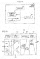
- Fig. 6 is a flow chart illustrating the example of the operation of the route display system according to the present embodiment
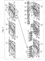
- Fig. 7 is a schematic diagram for use in illustrating the operation of the route display system according to the present embodiment.
- the input accepting unit 302 of the display apparatus 102 accepts inputting by a user in terms of starting point information and destination information (step S1). For example, as illustrated on a map 711 in Fig. 7 , the input accepting unit 302 may display a map image on the display unit 303 and may accept inputting of a starting point 721 and a destination 722 on the map image. Alternatively, without displaying a map image, the input accepting unit 302 may accept inputting of characters indicating an address or a facility name thereby accepting inputting f the starting point 721 and the destination 722.
- the transmission/reception unit 301 transmits, to the server apparatus 101, the starting point information and the destination information accepted by the input accepting unit 302 (step S2).
- the transmission/reception unit 201 of the server apparatus 101 receives the starting point information and the destination information transmitted from the display apparatus 102 (step S3).
- the route search unit 203 searches for a route from the starting point to the destination based on the starting point information and the destination information received via the transmission/reception unit 201 (step S4). For example, as illustrated on a map 712 in Fig. 7 , the route search unit 203 searches for a route 731 from the starting point 721 and the destination 722. The searching for the route may be performed according to a generally known technique, and thus a further detailed description thereof is omitted.
- the route search unit 203 extracts, as route information, information (represented in latitude, longitude, and travelling direction) associated with a plurality of passing points on the retrieved route (step S5). For example, as illustrated on a map 713 in Fig. 7 , the route search unit 203 extracts a plurality of passing points 741 to 746 on the retrieved route 731. Note that the passing points may be extracted at predetermined intervals such as every 30 meters. Alternatively, the route search unit 203 may determine in advance the number of passing points to be extracted and may divide the route at as many division points as the number of passing points, and the route search unit 203 may employ the resultant division points as the passing points.
- the predetermined number of passing points may be changed depending on the play time to play the captured images. For example, when the given play time is long, the number of passing points may be set to be large. On the other hand, when the given play time is short, the number of passing points may be set to be small.
- the image search unit 204 searches the plurality of captured images stored in the image storage unit 202 using, as search keys, the latitude, the longitude, and the travelling direction (the image capture direction) at each of one or more pieces of passing points information extracted by the route search unit 203 to detect and extract a captured image at an image capturing location exactly or closely corresponding to each passing point (step S6).
- the image search unit 204 performs the captured image extraction sequentially for each of the passing points in the order from the passing point closest to the starting point to the passing point closest to the destination such that a captured image with a latest image capturing date/time is extracted from one or more images captured at one or more image capturing locations located within an area with a predetermined diameter (for example, 5 meters) centered at each passing point.
- a predetermined diameter for example, 5 meters
- the image search unit 204 retrieves images captured at image capturing locations exactly identical or close to a passing point 741 from the plurality of captured images stored in the image storage unit 202.
- six captured images 751 are extracted as candidates for a captured image at the passing point 741.
- the image search unit 204 extracts a captured image 761 with a latest image capturing date/time from the six captured images 751. This makes it possible for a user to recognize a latest road condition. Thereafter, the image search unit 204 extracts captured images in a similar manner for respective other passing points 742 to 746,
- the image search unit 204 may detect an image capturing location closest to a passing point among one or more image capturing locations located within an area with a predetermined radius (for example, 5 meters) centered at the passing point, and the image search unit 204 may extract a captured image with a latest image capturing date/time from one or more images captured at the detected image capturing location.
- a predetermined radius for example, 5 meters
- the transmission/reception unit 201 transmits the route information and the captured images extracted by the route search unit 203, that is, the route information (the set of passing points information) and the plurality of captured images related to the location information to the display apparatus 102 (step S7).
- the transmission/reception unit 301 of the display apparatus 102 receives the route information and the plurality of captured images transmitted from the server apparatus 101 (step S8).
- the display unit 303 displays a map image representing the route from the starting point to the destination based on the route information received via the transmission/reception unit 301 (step S9).
- the input accepting unit 302 accepts inputting by a user in terms of a play command to start displaying the captured images on the route (step S10).
- the display unit 303 displays a passing point marker indicating the passing point while moving the passing point marker along the route from the location information closest to the starting point toward the passing point closest to the destination and the display unit 303 also displays the captured image related to the passing point indicated by the passing point marker sequentially from one passing point to another (step S11).
- the display unit 303 sequentially displays captured images 761 to 766 extracted for respective passing points 741 to 746.
- the images captured at the respective passing points are not displayed when a user passes through the respective passing points in the course of traveling.
- the images captured on the route from the starting point to the destination are sequentially displayed. This makes it possible for the user to recognize the actual road condition or traffic condition while virtually moving along the route from the starting point to the destination.
- the user is allowed to recognize the current road condition or traffic condition before the user starts to travel, and thus the user is allowed to select a proper route.
- the user is allowed to virtually travel along the route before starting the actual travel to get to know what the route looks like, which makes it possible to reduce an uneasy feeling of the user.
- Fig. 8A is a diagram illustrating an example of an overall service provided by the route display system according to the present embodiment
- Fig. 8B is a diagram illustrating an example in which a device manufacturer is a data center operation company
- Fig. 8C is a diagram illustrating an example in which one of or both of a device manufacturer and a management company are data center operation companies.
- the route display system includes a group 100, a data center operation company 110, and a service provider 120.
- the group 100 includes, for example, companies, organizations, and/or homes, with arbitrary scales.
- the group 100 includes a plurality of display apparatus 102 and communication apparatuses 103.
- the plurality of display apparatuses 102 may include a device (such as a smartphone, personal computer (PC), a TV set, a car navigation system equipped with a communication module, or the like) directly connectable to the Internet, and a device (such as a car navigation system equipped with no communication module, or the like) that is not capable of directly connecting to the Internet.
- a device such as a smartphone, personal computer (PC), a TV set, a car navigation system equipped with a communication module, or the like
- a device such as a car navigation system equipped with no communication module, or the like
- Users 10 use the plurality f display apparatuses 102 in the group 100.
- the data center operation company 110 includes a server apparatus 101.
- the server apparatus 101 is a virtual server that cooperates with various devices via the Internet.
- the main role of the server apparatus 101 is to manage big data or the like that is difficult to deal with by an average database management tool or the like.
- the data center operation company 110 manages data, manages the server apparatus 101, and operates the data center that deals with the data and the server apparatus 101. The details of the role of the data center operation company 110 will be described later.
- the data center operation company 110 is not limited to a company that only manages data or operates the server apparatus 101.
- a device manufacturer which develops and produces one of the plurality of display apparatuses 102, also manages data or manages the server apparatus 101 the device manufacturer functions as the data center operation company 110 as illustrated in Fig. 8B .
- the number of data center operation companies 110 is not limited to one.
- a device manufacturer and a management company cooperatively or collaborately mange data or operate the server apparatus 101, both or one of the device manufacturer and the management company functions as the data center operation company 110.
- the service provider 120 includes a server apparatus 121.
- the server apparatus 121 may include a memory or the like in a personal computer. Note that the service provider 120 may not include the server apparatus 121.
- the display apparatus 102 in the group 100 transmits the starting point information and the destination information to the server apparatus 101 in the data center operation company 110.
- the server apparatus 101 collects the starting point information and the destination information transmitted from the display apparatus 102 (as represented by an arrow 131 in Fig. 8A ).
- the starting point information and the destination information each may be represented, for example, by an address, a name of a building, a latitude, a longitude, and/or the like.
- the starting point information and the destination information may be provided directly from the plurality of display apparatuses 102 to the server apparatus 101 via the Internet.
- the starting point information and the destination information may be transmitted once from the plurality of display apparatuses 102 to the communication apparatus 103, and then the starting point information and the destination information may be provided to the server apparatus 101 from the communication apparatus 103.
- the server apparatus 101 of the data center operation company 110 provides the collected starting point information and destination information in fixed units to the service provider 120.
- the fixed unit may be a unit in which the data center operation company 110 is allowed to rearrange and provide the collected information to the service provider 120, or the fixed unit may a unit requested by the service provider 120.
- the unit is assumed to be fixed in the above example, the unit is not necessary to be fixed and the amount of information provided may be changed depending on the situation.
- the starting point information and the destination information are stored as required in the server apparatus 121 disposed in the service provider 120 (an arrow 132 in Fig. 8A ).
- the service provider 120 arranges the starting point information and the destination information so as to adapt to the service to be provided to a user and provides the arranged starting point information and the destination information to the user.
- the service may be provided to users 10 using the plurality of display apparatuses 102 or to external users 20.
- An example of a method of providing a service to users 10 or 20 is to directly provide the service to the users 10 or 20 from the service provider 120 (arrows 133 and 134 in Fig. 8A ).
- a service may be provided to a user 10, for example, again via the server apparatus 101 of the data center operation company 110 (arrows 135 and 136 in Fig. 8A ).
- the server apparatus 101 of the data center operation company 110 may arrange the starting point information and the destination information so as to adapt to the service to be provided to a user and may provide the arranged starting point information and destination information to the service provider 120.
- the service provided by the service provider 120 is to search for a route from the starting point to the destination.
- the server apparatus 101 of the data center operation company 110 transmits the starting point information and the destination information to the server apparatus 121 of the service provider 120.
- the server apparatus 121 searches for a route from the starting point to the destination based on the starting point information and the destination information and transmits route information obtained as a result of the search to the server apparatus 101.
- the server apparatus 101 extracts as plurality of captured images based on the received route information.
- the server apparatus 101 then transmits the route information and the plurality of captured image to the display apparatus 102.
- the display apparatus 102 displays a map image representing the route from the starting point to the destination based on the route information and displays the captured images sequentially in synchronization with the virtual moving from the starting point to the destination along the route.
- users 10 may be or may not be the same as users 20.
- Fig. 9 is a flow chart illustrating the method of generating the database according to the present embodiment.
- the transmission/reception unit 201 acquires a captured image of a view seen in a forward moving direction of a moving camera (step S21).
- the camera may be, for example, an in-vehicle camera.
- the camera captures a moving image and extracts one still image, for example, every second from the captured moving image and transmits the extracted still images to the server apparatus 101.
- the transmission/reception unit 201 receives the captured image of a view seen in a forward moving direction of a camera transmitted from the camera.
- the transmission/reception unit 201 acquires the image capturing date/time of the captured image (step S22). More specifically, the camera transmits the image capturing date/time of the captured image (still image) to the server apparatus 101. The transmission/reception unit 201 receives the image capturing date/time of the captured image transmitted from the camera. Note that the captured image is attached with image identification information identifying the captured image, and the camera transmits the image identification information together with the image capturing date/time data.
- the transmission/reception unit 201 acquires the location information indicating the location where the captured image was captured (step S23).
- the camera has, for example, a GPS to acquire the location information indicating the current location, and transmits the location information (the latitude and the longitude) indicating the location where the captured image (the still image) is captured to the server apparatus 101.
- the transmission/reception unit 201 receives from the camera the location information indicating the location where the captured image is captured. Note that the captured image is attached with image identification information identifying the captured image, and the camera transmits the image identification information together with the location information.
- the transmission/reception unit 201 acquires the image capture direction of the captured image calculated based on the location information of the current captured image and the location information of one of two captured images temporally before or after the current captured image (step S24).
- the camera calculates the image capture direction for the present extracted captured image from the location information (the latitude and the longitude) about the current extracted captured-image and the location information on the previously extracted captured-image. That is, from the location information about the current extracted captured-image and the location information about the previously extracted captured-image, it is possible to calculate the direction of the movement of the camera.
- the camera transmits the direction of the movement of the camera as the image capture direction to the server apparatus 101.
- the transmission/reception unit 201 receives the image capture direction of the captured image transmitted from the camera.
- the captured image is attached with image identification information identifying the captured image, and the camera transmits the image identification information together with the image capture direction data.
- the image capture direction is calculated by the camera in the present embodiment, but the present disclosure is not limited to this.
- the image capture direction may be calculated by the server apparatus 101. In this case, the image capture direction may be calculated in a similar manner to that described above.
- control unit 205 stores the acquired captured image, the image capturing date/time, the location information, and the image capture direction, in relation to each other, in the image storage unit 202 (the database).
- the server apparatus 101 acquires the captured image the image capturing date/time, the location information, and the image capture direction separately, the present disclosure is not limited to this.
- the server apparatus 101 may acquire all at the same time, or may two or three of the captured image, the image capturing date/time, the location information, and the image capture direction at the same time.
- the present disclosure provides the route display method, the route display apparatus, and the database generation method, which make it possible to recognize a current road condition or traffic condition in advance and select a proper route. Furthermore, in the case where a user is going to travel along a route for the first time, the user is allowed to virtually travel along the route before starting the actual travel to get to know what the route looks like, which makes it possible to reduce an uneasy feeling of the user.
- the present disclosure provides the useful route display method in the route display system that displays a route from a starting point to a destination, the useful route display apparatus that displays a route from a starting point to a destination, and the useful database generation method for generating a database used in the route display system.
Applications Claiming Priority (3)
| Application Number | Priority Date | Filing Date | Title |
|---|---|---|---|
| US201462048441P | 2014-09-10 | 2014-09-10 | |
| JP2015108441A JP6606354B2 (ja) | 2014-09-10 | 2015-05-28 | 経路表示方法、経路表示装置及びデータベース作成方法 |
| EP15183693.9A EP3002559A3 (de) | 2014-09-10 | 2015-09-03 | Routenanzeigeverfahren, routenanzeigevorrichtung und datenbankerzeugungsverfahren |
Related Parent Applications (1)
| Application Number | Title | Priority Date | Filing Date |
|---|---|---|---|
| EP15183693.9A Division EP3002559A3 (de) | 2014-09-10 | 2015-09-03 | Routenanzeigeverfahren, routenanzeigevorrichtung und datenbankerzeugungsverfahren |
Publications (2)
| Publication Number | Publication Date |
|---|---|
| EP3514495A2 true EP3514495A2 (de) | 2019-07-24 |
| EP3514495A3 EP3514495A3 (de) | 2019-10-30 |
Family
ID=54062669
Family Applications (2)
| Application Number | Title | Priority Date | Filing Date |
|---|---|---|---|
| EP19157453.2A Pending EP3514495A3 (de) | 2014-09-10 | 2015-09-03 | Routenanzeigeverfahren, routenanzeigevorrichtung und datenbankerzeugungsverfahren |
| EP15183693.9A Withdrawn EP3002559A3 (de) | 2014-09-10 | 2015-09-03 | Routenanzeigeverfahren, routenanzeigevorrichtung und datenbankerzeugungsverfahren |
Family Applications After (1)
| Application Number | Title | Priority Date | Filing Date |
|---|---|---|---|
| EP15183693.9A Withdrawn EP3002559A3 (de) | 2014-09-10 | 2015-09-03 | Routenanzeigeverfahren, routenanzeigevorrichtung und datenbankerzeugungsverfahren |
Country Status (2)
| Country | Link |
|---|---|
| US (1) | US9719794B2 (de) |
| EP (2) | EP3514495A3 (de) |
Families Citing this family (26)
| Publication number | Priority date | Publication date | Assignee | Title |
|---|---|---|---|---|
| US9972121B2 (en) * | 2014-04-22 | 2018-05-15 | Google Llc | Selecting time-distributed panoramic images for display |
| US9766344B2 (en) * | 2015-12-22 | 2017-09-19 | Honda Motor Co., Ltd. | Multipath error correction |
| US9900302B2 (en) | 2016-06-22 | 2018-02-20 | FinancialForce.com, Inc. | Seamless authentication for an application development platform |
| US10984359B2 (en) | 2016-06-23 | 2021-04-20 | FinancialForce.com, Inc. | Combining batch and queueable technologies in a salesforce platform for large volume parallel processing |
| US10496741B2 (en) | 2016-09-21 | 2019-12-03 | FinancialForce.com, Inc. | Dynamic intermediate templates for richly formatted output |
| US10527449B2 (en) * | 2017-04-10 | 2020-01-07 | Microsoft Technology Licensing, Llc | Using major route decision points to select traffic cameras for display |
| TWI684746B (zh) * | 2017-06-19 | 2020-02-11 | 大陸商北京嘀嘀無限科技發展有限公司 | 用於在地圖上顯示運輸工具的移動和行駛路徑的系統、方法和非暫時性電腦可讀取媒體 |
| JP7059540B2 (ja) * | 2017-09-08 | 2022-04-26 | 大日本印刷株式会社 | 画像管理サーバ、画像管理方法、及びプログラム |
| US10916132B2 (en) | 2017-11-22 | 2021-02-09 | International Business Machines Corporation | Vehicle dash cam sign reading |
| CN108230424B (zh) * | 2018-02-09 | 2021-11-02 | 城市生活(北京)资讯有限公司 | 一种线条显示方法及线条显示系统 |
| US11038689B2 (en) | 2018-03-01 | 2021-06-15 | FinancialForce.com, Inc. | Efficient block chain generation |
| CN108957498A (zh) * | 2018-05-03 | 2018-12-07 | 深圳市沃特沃德股份有限公司 | 一种显示运动轨迹的方法及其装置 |
| US10846481B2 (en) | 2018-06-29 | 2020-11-24 | FinancialForce.com, Inc. | Method and system for bridging disparate platforms to automate a natural language interface |
| JP7275556B2 (ja) | 2018-12-14 | 2023-05-18 | トヨタ自動車株式会社 | 情報処理システム、プログラム、及び情報処理方法 |
| JP2020095565A (ja) * | 2018-12-14 | 2020-06-18 | トヨタ自動車株式会社 | 情報処理システム、プログラム、及び情報処理方法 |
| US11200143B2 (en) | 2019-01-08 | 2021-12-14 | FinancialForce.com, Inc. | Software development framework for a cloud computing platform |
| US11107354B2 (en) * | 2019-02-11 | 2021-08-31 | Byton North America Corporation | Systems and methods to recognize parking |
| DE102019104505A1 (de) * | 2019-02-22 | 2020-08-27 | Dr. Ing. H.C. F. Porsche Aktiengesellschaft | Navigationssystem für ein Kraftfahrzeug |
| US10922485B2 (en) | 2019-07-10 | 2021-02-16 | FinancialForce.com, Inc. | Platform interpretation of user input converted into standardized input |
| US11455286B2 (en) * | 2019-08-06 | 2022-09-27 | FinancialForce.com, Inc. | History of slowly changing dimensions |
| US11796328B2 (en) * | 2019-09-30 | 2023-10-24 | Lyft, Inc. | Rendering location and orientation of public transportation vehicle icons within a graphical map display |
| JP7236677B2 (ja) * | 2019-12-25 | 2023-03-10 | パナソニックIpマネジメント株式会社 | 通信装置および通信方法 |
| CN111540026A (zh) * | 2020-03-24 | 2020-08-14 | 北京三快在线科技有限公司 | 动线图的绘制方法、装置、电子设备及存储介质 |
| JP7478622B2 (ja) * | 2020-08-20 | 2024-05-07 | 本田技研工業株式会社 | 情報処理装置、その情報処理方法、およびプログラム |
| JP7367709B2 (ja) * | 2021-01-20 | 2023-10-24 | トヨタ自動車株式会社 | 情報処理装置、情報処理システム、及び情報処理プログラム |
| CN113538828A (zh) * | 2021-07-15 | 2021-10-22 | 杭州海康威视数字技术股份有限公司 | 确定监控对象行进路线异常的方法、装置及设备 |
Citations (2)
| Publication number | Priority date | Publication date | Assignee | Title |
|---|---|---|---|---|
| JP2006337154A (ja) | 2005-06-01 | 2006-12-14 | Fujifilm Holdings Corp | 撮影表示装置 |
| JP3988683B2 (ja) | 2003-06-12 | 2007-10-10 | 株式会社日立製作所 | 画像情報取得システム及び車載端末 |
Family Cites Families (16)
| Publication number | Priority date | Publication date | Assignee | Title |
|---|---|---|---|---|
| US5559707A (en) * | 1994-06-24 | 1996-09-24 | Delorme Publishing Company | Computer aided routing system |
| JP3876463B2 (ja) * | 1996-11-18 | 2007-01-31 | ソニー株式会社 | 地図情報提供装置及び方法 |
| US8209120B2 (en) * | 1997-10-22 | 2012-06-26 | American Vehicular Sciences Llc | Vehicular map database management techniques |
| AU1707600A (en) * | 1998-10-21 | 2000-05-08 | American Calcar, Inc. | Positional camera and gps data interchange device |
| JP3749821B2 (ja) * | 1999-09-30 | 2006-03-01 | 株式会社東芝 | 歩行者用道案内システムおよび歩行者用道案内方法 |
| US6868169B2 (en) * | 2001-01-24 | 2005-03-15 | Hewlett-Packard Development Company, L.P. | System and method for geographical indexing of images |
| GB2377332A (en) | 2001-07-04 | 2003-01-08 | Hewlett Packard Co | Simulating a moving image from static cameras along a route |
| WO2003093954A2 (en) * | 2002-05-03 | 2003-11-13 | Pixearth, Corporation | A system to navigate within images spatially referenced to a computed space |
| JP2004212295A (ja) * | 2003-01-07 | 2004-07-29 | Mitsubishi Electric Corp | ナビゲーション装置 |
| GB2445964B (en) * | 2004-03-15 | 2008-10-08 | Tomtom Bv | GPS navigation device |
| DE102006038676A1 (de) | 2006-08-17 | 2008-02-21 | Bayerische Motoren Werke Ag | Fahrzeugnavigationssystem |
| EP2414778B1 (de) * | 2009-04-01 | 2018-06-06 | Uber Technologies, Inc. | Interessepunkt-suche auf einer route mit rückweg |
| US20110099507A1 (en) * | 2009-10-28 | 2011-04-28 | Google Inc. | Displaying a collection of interactive elements that trigger actions directed to an item |
| JP5119288B2 (ja) * | 2010-03-15 | 2013-01-16 | シャープ株式会社 | 携帯端末装置、情報出力システム、情報出力方法、プログラムおよび記録媒体 |
| US9215590B2 (en) * | 2012-04-20 | 2015-12-15 | Bank Of America Corporation | Authentication using vehicle data pairing |
| US9324195B2 (en) | 2013-02-26 | 2016-04-26 | Polaris Industries Inc. | Recreational vehicle interactive, telemetry, mapping, and trip planning system |
-
2015
- 2015-09-03 EP EP19157453.2A patent/EP3514495A3/de active Pending
- 2015-09-03 EP EP15183693.9A patent/EP3002559A3/de not_active Withdrawn
- 2015-09-03 US US14/844,028 patent/US9719794B2/en active Active
Patent Citations (2)
| Publication number | Priority date | Publication date | Assignee | Title |
|---|---|---|---|---|
| JP3988683B2 (ja) | 2003-06-12 | 2007-10-10 | 株式会社日立製作所 | 画像情報取得システム及び車載端末 |
| JP2006337154A (ja) | 2005-06-01 | 2006-12-14 | Fujifilm Holdings Corp | 撮影表示装置 |
Also Published As
| Publication number | Publication date |
|---|---|
| EP3002559A3 (de) | 2016-08-10 |
| EP3002559A2 (de) | 2016-04-06 |
| EP3514495A3 (de) | 2019-10-30 |
| US9719794B2 (en) | 2017-08-01 |
| US20160069703A1 (en) | 2016-03-10 |
Similar Documents
| Publication | Publication Date | Title |
|---|---|---|
| US9719794B2 (en) | Route display method, route display apparatus, and database generation method | |
| DE602004011153T2 (de) | Eine Vorrichtung, System und Verfahren für die Verarbeitung von statistischen Verkehrsinformationen | |
| CN104937650B (zh) | 用于定位可用停车位的系统及方法 | |
| KR101847833B1 (ko) | 교통량 예측 시스템, 차량용 표시 장치, 차량 및 교통량 예측 방법 | |
| DE602004002048T2 (de) | Gerät, System und Verfahren zur Signaliseren von der Verkehrslage | |
| JP4771365B2 (ja) | 経路案内システム、経路案内方法及びプログラム | |
| EP2843368B1 (de) | Verfahren und System zur computerbasierten Navigation | |
| CN104729515B (zh) | 导航路径比对方法及系统 | |
| JP6324196B2 (ja) | 情報処理装置、情報処理方法および情報処理システム | |
| JP2010169441A (ja) | 情報出力端末、情報出力方法、情報出力プログラムおよび記録媒体 | |
| JP4742916B2 (ja) | ナビゲーションシステム | |
| CN110741227A (zh) | 地标辅助导航 | |
| JP6682193B2 (ja) | 通知システム、サーバ装置、通信端末装置、プログラム及び通知方法 | |
| JP4939380B2 (ja) | 情報管理サーバ、ナビゲーション装置、情報管理方法、ナビゲーション方法、情報管理プログラム、ナビゲーションプログラム、および記録媒体 | |
| JP6606354B2 (ja) | 経路表示方法、経路表示装置及びデータベース作成方法 | |
| JP5172753B2 (ja) | ナビサーバおよびナビシステム | |
| JP6731667B1 (ja) | 走行ルートの検索方法 | |
| JP2016099442A (ja) | 地図データ作成方法、地図表示方法、地図データ作成装置および地図表示装置 | |
| JP6765333B2 (ja) | 情報処理装置、プログラム | |
| JP2020004225A (ja) | 情報処理システム、情報処理プログラムおよび情報処理方法 | |
| CN110753827A (zh) | 具有交互式转弯图形的数字地图上的路线 | |
| JP5509932B2 (ja) | 移動通信装置、プログラム及び周辺情報出力方法 | |
| JP2017227445A (ja) | 自動運転装置 | |
| JP5389299B1 (ja) | 情報提示システム及び情報提示方法、サーバ装置及び端末装置、情報提示用プログラム並びに情報記録媒体 | |
| CN106781470B (zh) | 城市道路的运行速度的处理方法及装置 |
Legal Events
| Date | Code | Title | Description |
|---|---|---|---|
| PUAI | Public reference made under article 153(3) epc to a published international application that has entered the european phase |
Free format text: ORIGINAL CODE: 0009012 |
|
| STAA | Information on the status of an ep patent application or granted ep patent |
Free format text: STATUS: THE APPLICATION HAS BEEN PUBLISHED |
|
| AC | Divisional application: reference to earlier application |
Ref document number: 3002559 Country of ref document: EP Kind code of ref document: P |
|
| AK | Designated contracting states |
Kind code of ref document: A2 Designated state(s): AL AT BE BG CH CY CZ DE DK EE ES FI FR GB GR HR HU IE IS IT LI LT LU LV MC MK MT NL NO PL PT RO RS SE SI SK SM TR |
|
| AX | Request for extension of the european patent |
Extension state: BA ME |
|
| PUAL | Search report despatched |
Free format text: ORIGINAL CODE: 0009013 |
|
| AK | Designated contracting states |
Kind code of ref document: A3 Designated state(s): AL AT BE BG CH CY CZ DE DK EE ES FI FR GB GR HR HU IE IS IT LI LT LU LV MC MK MT NL NO PL PT RO RS SE SI SK SM TR |
|
| AX | Request for extension of the european patent |
Extension state: BA ME |
|
| RIC1 | Information provided on ipc code assigned before grant |
Ipc: G06T 1/00 20060101ALI20190926BHEP Ipc: G06F 16/51 20190101ALI20190926BHEP Ipc: G01C 21/36 20060101AFI20190926BHEP Ipc: G06F 16/58 20190101ALI20190926BHEP Ipc: G09B 29/00 20060101ALI20190926BHEP |
|
| STAA | Information on the status of an ep patent application or granted ep patent |
Free format text: STATUS: REQUEST FOR EXAMINATION WAS MADE |
|
| 17P | Request for examination filed |
Effective date: 20200408 |
|
| RBV | Designated contracting states (corrected) |
Designated state(s): AL AT BE BG CH CY CZ DE DK EE ES FI FR GB GR HR HU IE IS IT LI LT LU LV MC MK MT NL NO PL PT RO RS SE SI SK SM TR |
|
| STAA | Information on the status of an ep patent application or granted ep patent |
Free format text: STATUS: EXAMINATION IS IN PROGRESS |
|
| 17Q | First examination report despatched |
Effective date: 20221118 |