EP3501893A1 - Vorrichtung zum aufhängen einer lampe in einem fahrzeug - Google Patents
Vorrichtung zum aufhängen einer lampe in einem fahrzeug Download PDFInfo
- Publication number
- EP3501893A1 EP3501893A1 EP17208550.8A EP17208550A EP3501893A1 EP 3501893 A1 EP3501893 A1 EP 3501893A1 EP 17208550 A EP17208550 A EP 17208550A EP 3501893 A1 EP3501893 A1 EP 3501893A1
- Authority
- EP
- European Patent Office
- Prior art keywords
- lamp
- axis
- vehicle
- pivot
- guiding
- Prior art date
- Legal status (The legal status is an assumption and is not a legal conclusion. Google has not performed a legal analysis and makes no representation as to the accuracy of the status listed.)
- Granted
Links
- 239000000725 suspension Substances 0.000 title claims abstract description 22
- 239000006096 absorbing agent Substances 0.000 claims abstract description 59
- 230000006835 compression Effects 0.000 description 10
- 238000007906 compression Methods 0.000 description 10
- 238000010521 absorption reaction Methods 0.000 description 8
- 230000006378 damage Effects 0.000 description 4
- 230000001419 dependent effect Effects 0.000 description 2
- 230000014509 gene expression Effects 0.000 description 2
- GINJFDRNADDBIN-FXQIFTODSA-N bilanafos Chemical compound OC(=O)[C@H](C)NC(=O)[C@H](C)NC(=O)[C@@H](N)CCP(C)(O)=O GINJFDRNADDBIN-FXQIFTODSA-N 0.000 description 1
- 230000002349 favourable effect Effects 0.000 description 1
- 239000006260 foam Substances 0.000 description 1
- 239000002184 metal Substances 0.000 description 1
- 238000012986 modification Methods 0.000 description 1
- 230000004048 modification Effects 0.000 description 1
- 230000003068 static effect Effects 0.000 description 1
- 239000013589 supplement Substances 0.000 description 1
- 238000003466 welding Methods 0.000 description 1
Images


Classifications
-
- B—PERFORMING OPERATIONS; TRANSPORTING
- B60—VEHICLES IN GENERAL
- B60Q—ARRANGEMENT OF SIGNALLING OR LIGHTING DEVICES, THE MOUNTING OR SUPPORTING THEREOF OR CIRCUITS THEREFOR, FOR VEHICLES IN GENERAL
- B60Q1/00—Arrangement of optical signalling or lighting devices, the mounting or supporting thereof or circuits therefor
- B60Q1/02—Arrangement of optical signalling or lighting devices, the mounting or supporting thereof or circuits therefor the devices being primarily intended to illuminate the way ahead or to illuminate other areas of way or environments
- B60Q1/04—Arrangement of optical signalling or lighting devices, the mounting or supporting thereof or circuits therefor the devices being primarily intended to illuminate the way ahead or to illuminate other areas of way or environments the devices being headlights
- B60Q1/0491—Shock absorbing devices therefor
-
- B—PERFORMING OPERATIONS; TRANSPORTING
- B60—VEHICLES IN GENERAL
- B60R—VEHICLES, VEHICLE FITTINGS, OR VEHICLE PARTS, NOT OTHERWISE PROVIDED FOR
- B60R21/00—Arrangements or fittings on vehicles for protecting or preventing injuries to occupants or pedestrians in case of accidents or other traffic risks
- B60R21/34—Protecting non-occupants of a vehicle, e.g. pedestrians
- B60R2021/343—Protecting non-occupants of a vehicle, e.g. pedestrians using deformable body panel, bodywork or components
Definitions
- the invention relates to a device for suspension of a lamp in a vehicle, and a vehicle comprising such a lamp suspension device.
- any lamp arranged in the front of the vehicle may constitute a relative hard structure.
- vehicles are usually adapted to yield in response to forces generated by a pedestrian impact.
- the vehicle may be equipped with a pedestrian air bag or a device for changing the inclination angle of the hood, etc.
- An objective of the invention is to provide a device for suspension of a lamp in a vehicle, which device will reduce pedestrian injuries in case of a head impact to the lamp.
- a device for suspension of a lamp in a vehicle which device comprises a guiding means for guiding the lamp to move relative to the vehicle from a first position to a second position in case of an impact between the lamp and an object, and at least one energy absorber for counteracting movement of the lamp from the first position to the second position, wherein the guiding means is arranged for guiding the lamp to move downwardly in a movement direction having a movement direction component in parallel with the Z-axis while the movement of the lamp being counteracted by said energy absorber.
- the invention is based on the insight that by such a device, energy can be absorbed during impact even if the space close to the lamp is limited, particularly for a lamp mounted on a position in the hood and/or the front wheel fender area where the lamp has a major part of an exterior surface facing upwardly with a surface normal having a major direction component in parallel with the Z-axis. This in turn will improve the pedestrian safety in case of an impact.
- the directions and axes used herein, i.e. the X-axis, Y-axis and the Z-axis, constitute a cartesian coordinate system arranged relative to a vehicle such that the X-axis is in parallel with the horizontal longitudinal extension of the vehicle, the Y-axis is in parallel with the horizontal lateral extension of the vehicle, thus being perpendicular to the X-axis, and the Z-axis is in parallel with a vertical extension of the vehicle, thus being perpendicular to the X-axis and the Y-axis.
- the guiding means is arranged for guiding the lamp to move such that the movement direction component in parallel with the Z-axis is larger than any movement direction component in parallel with the X-axis or Y-axis, and preferably the guiding means is arranged for guiding the lamp such that the movement direction of the lamp is substantially in parallel with the Z-axis.
- the energy absorption in the Z-direction can be further improved.
- the device comprises one said energy absorber for counteracting pivot motion of the lamp, and the guiding means is arranged for guiding the lamp to pivot about an axis being transverse relative to the Z-axis while the pivot motion of the lamp being counteracted by said energy absorber.
- energy can be absorbed both during translation motion and pivot motion of the lamp.
- the distribution of the energy absorption on the translation motion and the pivot motion, respectively may depend on the impact position and/or direction, the counterforce from the energy absorber acting against the movement in the Z-direction and the counter force or torque from the energy absorber acting against the pivot motion can be adapted to each other.
- the pivot axis is substantially perpendicular to the X-axis, and preferably the pivot axis extends in a direction substantially in parallel with the Y-axis.
- the energy absorption can be further improved, since the orientation of the pivot axis relative an impact direction is often favourable.
- the guiding means is arranged for making the lamp pivotable about the pivot axis in a first pivot direction and a second pivot direction opposite to the first pivot direction. Herby, the ability of the lamp to pivot during energy absorption is less dependent on the impact position.
- the pivot axis is displaceable and arranged to move together with the lamp in the movement direction.
- pivot motion is possible for various positions of the lamp.
- the position of impact be very close to the pivot axis not causing any significant pivot motion, movement of the lamp with a movement direction component in parallel with the Z-axis while absorbing energy is still possible.
- said at least one energy absorber is arranged for counteracting both motion of the lamp in the movement direction and pivot motion about said pivot axis.
- the energy absorption function can be achieved by means of relative few components.
- the device comprises one said energy absorber arranged on each side of the pivot axis.
- an effective energy absorption can be provided independent on the pivot direction of the lamp.
- the guiding means is arranged for guiding the lamp to move downwardly in a movement direction having a major movement direction component in parallel with the Z-axis while the movement of the lamp being counteracted by one said energy absorber, or to move inwardly in a movement direction having a major movement direction component in parallel with the X-axis while the movement of the lamp being counteracted by one said energy absorber, depending on the impact position and direction.
- the device enables movement of the lamp during energy absorption even in case of an unfavourable impact position and/or direction forcing the lamp in a direction without any significant component in parallel with the Z-axis.
- a further objective is to provide an arrangement for suspension of a lamp in a vehicle, which arrangement can reduce pedestrian injuries in case of a head impact to the lamp and be easily mounted to a vehicle.
- an arrangement for suspension of a lamp in a vehicle wherein the arrangement has a guiding means for guiding the lamp to move relative to a vehicle from a first position to a second position in case of an impact between the lamp and an object, the guiding means comprises at least one flange unit for receiving the lamp, and the arrangement further has at least one holder for holding an energy absorber for counteracting movement of the lamp from the first position to the second position, and wherein said at least one flange unit and said at least one holder are integrated in one single unit attachable to the vehicle.
- a further objective is to provide a vehicle, which vehicle will reduce pedestrian injuries in case of a head impact to a vehicle lamp. This objective is achieved by a vehicle provided with a device according to the invention.
- Fig. 1 is a perspective view of a vehicle 1 and Fig. 1b shows the vehicle 1 in a side view.
- a cartesian coordinate system having axes X, Y and Z is also shown.
- the vehicle 1 and the individual components will be described herein with reference to this coordinate system.
- the vehicle 1 has two supplement lamps 2 for daytime running light (DRL) arranged in the hood and front wheel fender area of the vehicle 1.
- DRL daytime running light
- One such lamp 2 is arranged on the left side of the vehicle 1 at the boundary between the hood 3 and the adjacent front wheel fender 4. In the same way the other lamp 2 is arranged on the right side of the vehicle.
- the lamp 2 can be arranged such that a major part of an exterior surface 5 of the lamp faces upwardly with a surface normal 6 having a major direction component 6a in parallel with the Z-axis. This does not necessarily mean that the surface 5 of the lamp is completely horizontal.
- the lamp 2 on the right side of the vehicle 1 is illustrated, the lamp 2 is somewhat inclined relative to the X-axis, but the surface normal 6 of the lamp 2 has a larger component 6a in a direction in parallel with the Z-axis than a component 6b in a direction in parallel with the X-axis.
- the surface 5 can also be somewhat inclined relative to the Y-axis.
- the exterior surface 5 of the lamp can be inclined relative to the X-axis with an angle ⁇ selected in the range 0 ⁇ 45°, preferably 0 ⁇ 30°, and relative to the Y-axis with an angle ⁇ selected in the range 0 ⁇ 45°, preferably 0 ⁇ 30°.
- the lamp 2 is inclined relative to the X-axis, preferably the rear part of the exterior surface of the lamp is arranged at a higher level than the front part of the exterior surface of the lamp 2, and if the lamp 2 is inclined relative to the Y-axis, preferably the inner part of the exterior surface of the lamp 2 is arranged at a higher level than the outer part of the exterior surface of the lamp 2.
- the exterior surface of the lamp does not need to be horizontal, preferably the projected surface of the lamp seen in a direction in parallel with the Z-axis has however a considerable area that could be subject to an impact with an object.
- the lamp 2 is suitably arranged such that an exterior surface 5 of the lamp is substantially flush with an exterior surface of the hood 3 and the front wheel fender 4 of the vehicle 1.
- the lamp 2 is suspended in the vehicle 1 by means of a vehicle lamp suspension device 7 that will be described in detail hereinbelow.
- Fig. 2 shows a device 7 for suspension of the lamp 2 in the vehicle 1.
- the device 7 comprises a guiding means 8 for guiding the lamp 2 to move relative to the vehicle 1 from a first position to a second position in case of an impact between the lamp and an object.
- the device 7 also comprises at least one energy absorber 9a, 9b for counteracting movement of the lamp from the first position to the second position.
- the guiding means 8 is arranged for guiding the lamp 2 to move downwardly in a movement direction 10 having a movement direction component in parallel with the Z-axis while the movement of the lamp 2 being counteracted by one said energy absorber 9a, 9b.
- the guiding means 8 is suitably arranged for guiding the lamp 2 to move such that the movement direction component in parallel with the Z-axis is larger than any movement direction component in parallel with the X-axis or Y-axis, and preferably such that the movement direction 10 of the lamp is substantially in parallel with the Z-axis.
- movement direction refers to the resulting translation motion direction, whereas "movement direction component” is a component contributing to the "movement direction”.
- the lamp 2 is guided by the guiding means 8 in a substantially vertical direction only, in other embodiments of the device 7 the guiding means could however be arranged for guiding the lamp such that the movement direction has a movement direction component also in parallel with the X-axis and/or the Y-axis while the lamp being guided to move downwards with a movement direction component in parallel with the Z-axis.
- the energy absorber 9a, 9b can be any kind of metal spring, foam, plastic component, etc., that preferably has a non-linear spring constant.
- a spring can have a non-linear spring constant increasing with increased compression of the spring.
- the lamp suspension device 7 or any other part of the vehicle 1 may comprise an attachment component for mechanical connection of the lamp 2 to the vehicle 1.
- an attachment component can be used for connecting the lamp to the vehicle and keeping the lamp in an intended position, for example the first position mentioned above, in absence of any impact.
- the lamp is releasable from this connection to the vehicle in case of an impact.
- the lamp has preferably a break off feature withstanding static loads.
- such an attachment component can be broken in case of an impact and thereafter the movement of the lamp during impact is mainly determined by the guiding means and the energy absorber.
- the guiding means can be used also for connecting the lamp to the vehicle and keeping the lamp in the intended first position.
- the suspension device 7 may comprise one said energy absorber 9a, 9b for counteracting pivot motion of the lamp 2.
- the guiding means 8 is suitably arranged for guiding the lamp 2 to pivot about an axis 11 being transverse relative to the Z-axis while the pivot motion of the lamp 2 being counteracted by said energy absorber 9a, 9b.
- transverse is meant a direction that can deviate from a direction perpendicular to the Z-axis. The deviation can be within ⁇ 30°, preferably ⁇ 20° and often within ⁇ 10° from a direction perpendicular to the Z-axis. In the example embodiment illustrated in Fig.
- the pivot axis 11 is arranged substantially perpendicular to the X-axis and the Z-axis.
- the pivot axis 11 is arranged to extend in a direction substantially in parallel with the Y-axis for pivoting of the lamp 2 in case of an impact.
- the guiding means 8 is suitably arranged for making the lamp 2 pivotable about the pivot axis 11 in a first pivot direction 12 and a second pivot direction 13 opposite to the first pivot direction 12.
- pivot axis 11 can also be displaceable and arranged to move together with the lamp 2 in the movement direction 10.
- the pivot axis 11 is moved downwards in the vertical direction when the lamp 2 is moved downwards during impact.
- the guiding means 8 can comprise at least one flange unit 14 having a slot 15 for receiving a pin 16.
- the slot 15 is arranged for guiding the pin 16 to move in the movement direction 10, here in the vertical direction, and pivot about the pivot axis 11 relative to the flange unit 14.
- the flange unit 14 is suitably adapted to be attached to the vehicle 1 and receive the pin 16 which is arranged on the lamp 2, it would also be possible to instead arrange the pin to be fixed relative to the vehicle and arrange the slot in the lamp.
- the device 7 may comprise two said flange units 14, 14b spaced apart with a distance along the pivot axis 11. The distance is suitably adapted for accommodating the lamp 2 between the two flange units 14, 14b.
- Each energy absorber 9a, 9b can be arranged for counteracting translation motion or pivot motion of the lamp 2. With reference to Fig. 2 , one and the same energy absorber 9a, 9b is arranged for counteracting both movement of the lamp 2 in the movement direction 10 and pivot motion about the pivot axis 11.
- the vehicle lamp suspension device 7 illustrated in Fig. 2 has a first energy absorber 9a including a first spring 17 and a second energy absorber 9b including a second spring 18.
- the first energy absorber 9a is arranged on a first side of the pivot axis 11 and the second energy absorber 9b is arranged on a second side of the pivot axis 11.
- each energy absorber 9a, 9b will counteract motion of the lamp 2 in the vertical direction, but also counteract pivot motion about the pivot axis 11, since each energy absorber 9a, 9b is arranged at a distance from the pivot axis 11 with respect to the position along the X-axis.
- the first energy absorber 9a and the second energy absorber 9b are suitably attached to the vehicle 1.
- the first spring 17 and the second spring 18 are pivotally attached to the vehicle.
- the upper end of each spring 17, 18 can be attached to an intermediate plate 19 to be in contact with the lamp 2 when the spring is compressed by the lamp 2.
- an energy absorber in form of a spring arranged such as the first and second energy absorbers 9a, 9b in Fig. 2
- the energy absorber could be arranged for providing a counterforce when the energy absorber is stretched.
- a first end of the spring can be attached to the vehicle and a second end of the spring can be attached to the lamp.
- Fig. 4 shows a variant of an energy absorber 9.
- the energy absorber 9 comprises two springs 20, 21.
- a compression spring 20 is arranged to provide a counterforce in the compression direction of the spring 20. Further, the compression spring 20 is arranged at the vehicle 1 for allowing the compression spring 20 to pivot relative to the vehicle 1.
- a further spring (schematically illustrated) 21 is arranged to extend between the vehicle 1 and the compression spring 20, which further spring 21 counteracts pivot motion of the compression spring 20.
- the compression spring 20 is pivotable about its attachment point to the vehicle 1 while such pivot motion is counteracted by the further spring 21.
- Fig. 4 shows a first state where the compression spring 20 is not loaded (dotted lines) and a second state where the compression spring 20 has been compressed and pivoted relative to the vehicle 1.
- absorption of energy during pivoting of the lamp can be provided by an energy absorber (not shown) that is arranged at the pivot axis.
- an energy absorber (not shown) that is arranged at the pivot axis.
- a spring arranged to extend between the pin and a vehicle part, such as the flange unit, can be used. The spring will counteract pivot motion of the pin, and thus the lamp, relative to the vehicle part.
- Fig. 5 shows a variant of a guiding means 28.
- the guiding means 28 is arranged for guiding the lamp to move downwardly in a movement direction 10 having a major movement direction component in parallel with the Z-axis while the movement of the lamp being counteracted by an energy absorber, or to move inwardly in a movement direction 10b having a major movement direction component in parallel with the X-axis while the movement of the lamp being counteracted by an energy absorber, depending on the impact position and direction.
- the guiding means 28 is arranged for guiding the lamp in different directions 10, 10b.
- the guiding means 28 comprises a flange unit 24 having a slot 25 with a first slot part 25a and a second slot part 25b for receiving a pin 26.
- the first slot part 25a and the second slot part 25b are arranged with different extension directions for providing alternative guiding directions for the pin 26.
- the first slot part 25a is arranged for guiding the pin 26 to move in a direction 10 substantially in parallel with the Z-axis and pivot about the pivot axis 31 relative to the flange unit 24.
- the second slot part 25b is arranged for guiding the pin 26 to move in a direction substantially in parallel with the X-axis and pivot about the pivot axis 31 relative to the flange unit 24.
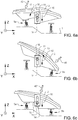
- Figs. 6a, 6b and 6c show some examples of movement of the lamp 2 from the first position to the second position due to an impact between the lamp 2 and an object 40.
- the expressions rear part, front part and centre part of the lamp are used with respect to the position along the X-axis.
- Fig. 6a shows the lamp 2 where the lamp has moved from the first position (see Fig. 2 ) to the second position due to an impact with an object 40.
- the lamp 2 has been hit by the object 40 in a rear part of the lamp 2 causing the lamp to pivot about the pivot axis 11 in a first pivot direction 12 and move downwards in the vertical direction 10.
- Energy of the impact is absorbed by the first energy absorber 9a that is compressed during the movement of the lamp from the first position to the second position.
- the flange unit 14 is fixed relative to the vehicle 1.
- Fig. 6b shows the lamp 2 where the lamp has moved from the first position (see Fig. 2 ) to the second position due to an impact with an object 40'.
- the lamp 2 has been hit by the object 40' in a front part of the lamp 2 causing the lamp to pivot about the pivot axis 11 in a second pivot direction 13 and move downwards in the vertical direction 10.
- Energy of the impact is absorbed by the second energy absorber 9b that is compressed during the movement of the lamp from the first position to the second position.
- the flange unit 14 is fixed relative to the vehicle 1.
- Fig. 6c shows the lamp 2 where the lamp has moved from the first position (see Fig. 2 ) to the second position due to an impact with an object 40".
- the lamp has been hit by the object 40" in a centre part of the lamp 2 causing the lamp to move downwards in the vertical direction 10.
- the pivot motion about the pivot axis 11 is almost negligible. Energy of the impact is absorbed by the first energy absorber 9a and the second energy absorber 9b that are compressed during the movement of the lamp from the first position to the second position.
- the flange unit 14 is fixed relative to the vehicle 1.
- Fig. 7 is a front view of a variant of a vehicle lamp suspension device 70 seen in a direction in parallel to the X-axis.
- the device 70 has a guiding means 38 arranged for guiding the lamp 2 to pivot about an axis 41 that is substantially perpendicular to the Y-axis. Further, the pivot axis 41 suitably extends in a direction substantially in parallel with the X-axis.
- Fig. 8 shows an example of movement of the lamp from the first position to the second position due to an impact between the lamp 2 and an object 40"'.
- the lamp 2 has moved from the first position (see Fig. 7 ) to the second position due to an impact with an object 40"'.
- the lamp 2 has been hit by the object causing the lamp to pivot about the pivot axis 41 and move downwards in the vertical direction 10.
- Energy of the impact is absorbed by the energy absorber 9 that is compressed during the movement of the lamp from the first position to the second position.
- Figs. 9 and 10 show an arrangement 50 for suspension of a lamp 2 in a vehicle 1.
- Fig. 9 is a side view and Fig. 10 is a front view of the arrangement.
- the arrangement 50 has a guiding means 58 for guiding a lamp (not shown) to move relative to a vehicle 1 from a first position to a second position in case of an impact between the lamp and an object.
- the guiding means 58 has at least one flange unit 54a for receiving the lamp.
- the arrangement has at least one holder 51a, 51b for holding an energy absorber 59a, 59b for counteracting movement of the lamp from the first position to the second position.
- the guiding means 58 comprising two flange units 54a, 54b spaced apart from each other for receiving the lamp, and a first holder 51a for holding a first energy absorber 59a and a second holder 51b for holding a second energy absorber 59b.
- the arrangement 50 further comprises a plate 52 which can be attached to the vehicle 1.
- the two flange units 54a, 54b and the first and second holders 51a, 51b are attached to the plate 52 to be integrated in one and the same unit 60.
- This unit 60 is in turn attachable to the vehicle 1 by for example a bolted joint, welding or any other suitable means.
- the flange units and the holders are made in one piece.
Priority Applications (4)
| Application Number | Priority Date | Filing Date | Title |
|---|---|---|---|
| EP17208550.8A EP3501893B1 (de) | 2017-12-19 | 2017-12-19 | Vorrichtung zum aufhängen einer lampe in einem fahrzeug |
| CN201880080139.8A CN111601735B (zh) | 2017-12-19 | 2018-11-21 | 一种用于在车辆中悬挂灯的装置 |
| PCT/CN2018/116706 WO2019120021A1 (en) | 2017-12-19 | 2018-11-21 | A device for suspension of a lamp in a vehicle |
| US16/893,015 US11230222B2 (en) | 2017-12-19 | 2020-06-04 | Device for suspension of a lamp in a vehicle |
Applications Claiming Priority (1)
| Application Number | Priority Date | Filing Date | Title |
|---|---|---|---|
| EP17208550.8A EP3501893B1 (de) | 2017-12-19 | 2017-12-19 | Vorrichtung zum aufhängen einer lampe in einem fahrzeug |
Publications (2)
| Publication Number | Publication Date |
|---|---|
| EP3501893A1 true EP3501893A1 (de) | 2019-06-26 |
| EP3501893B1 EP3501893B1 (de) | 2023-12-06 |
Family
ID=60781738
Family Applications (1)
| Application Number | Title | Priority Date | Filing Date |
|---|---|---|---|
| EP17208550.8A Active EP3501893B1 (de) | 2017-12-19 | 2017-12-19 | Vorrichtung zum aufhängen einer lampe in einem fahrzeug |
Country Status (4)
| Country | Link |
|---|---|
| US (1) | US11230222B2 (de) |
| EP (1) | EP3501893B1 (de) |
| CN (1) | CN111601735B (de) |
| WO (1) | WO2019120021A1 (de) |
Cited By (1)
| Publication number | Priority date | Publication date | Assignee | Title |
|---|---|---|---|---|
| FR3129886A1 (fr) * | 2021-12-08 | 2023-06-09 | Valeo Vision | Dispositif lumineux d’un véhicule automobile |
Families Citing this family (3)
| Publication number | Priority date | Publication date | Assignee | Title |
|---|---|---|---|---|
| FR3088689B1 (fr) * | 2018-11-19 | 2020-11-06 | Plastic Omnium Cie | Dispositif de véhicule avec système de fixation pour zones critiques |
| DE102021213275A1 (de) | 2021-11-25 | 2023-05-25 | Volkswagen Aktiengesellschaft | Befestigungssystem, Reparaturverfahren und Kraftfahrzeug |
| US20240042959A1 (en) * | 2022-08-08 | 2024-02-08 | Rivian Ip Holdings, Llc | Deployable protection plate |
Citations (7)
| Publication number | Priority date | Publication date | Assignee | Title |
|---|---|---|---|---|
| DE2727517A1 (de) * | 1977-06-18 | 1978-12-21 | Daimler Benz Ag | Kraftwagen mit vorderem stossfaenger |
| JPH11165581A (ja) * | 1997-12-01 | 1999-06-22 | Mitsubishi Motors Corp | 車両用灯具の取付構造 |
| JP2000280816A (ja) * | 1999-03-30 | 2000-10-10 | Mitsubishi Motors Corp | 衝撃緩和機構 |
| DE10030373A1 (de) * | 2000-06-21 | 2002-01-03 | Volkswagen Ag | Befestigungsvorrichtung für einen Kraftfahrzeugscheinwerfer |
| FR2844755A1 (fr) * | 2002-09-20 | 2004-03-26 | Valeo Vision | Projecteur de vehicule automobile comportant un systeme d'amortissement |
| FR2901202A1 (fr) * | 2006-05-22 | 2007-11-23 | Renault Sport Technologies Soc | Projecteur de vehicule automobile et vehicule automobile comportant un tel projecteur |
| CN101469820A (zh) * | 2007-12-27 | 2009-07-01 | 上海现代摩比斯汽车零部件有限公司 | 行人保护用头灯 |
Family Cites Families (15)
| Publication number | Priority date | Publication date | Assignee | Title |
|---|---|---|---|---|
| US3284100A (en) * | 1965-03-01 | 1966-11-08 | Lewis M Goff | Buffer device for pusher vehicles |
| JPH02127138A (ja) * | 1988-11-02 | 1990-05-15 | Koito Mfg Co Ltd | 車輌用灯具の取付構造 |
| JP3597606B2 (ja) * | 1995-07-17 | 2004-12-08 | 本田技研工業株式会社 | 車両用灯体の取付構造 |
| DE10149120C1 (de) * | 2001-10-05 | 2003-04-10 | Daimler Chrysler Ag | Übergangsbereich von Motor- bzw. Fronthaube und Scheinwerfer |
| US20030142503A1 (en) * | 2002-01-30 | 2003-07-31 | Ford Global Technologies, Inc. | Pedestrian protection headlamp |
| US7090371B1 (en) * | 2002-09-17 | 2006-08-15 | George Bonar | Removable headlamp for a vehicle |
| FR2844757B1 (fr) * | 2002-09-20 | 2005-10-07 | Valeo Vision | Projecteur de vehicule automobile comportant des moyens perfectionnes de liaison au chassis du vehicule |
| DE10258629B4 (de) * | 2002-12-16 | 2006-07-27 | Daimlerchrysler Ag | Fahrzeug |
| DE10357920B4 (de) * | 2003-12-11 | 2009-07-09 | Daimler Ag | Fahrzeug-Beleuchtungseinrichtung |
| JP2005186738A (ja) * | 2003-12-25 | 2005-07-14 | Nissan Motor Co Ltd | ヘッドランプの取付け構造 |
| JP4715444B2 (ja) * | 2005-10-21 | 2011-07-06 | マツダ株式会社 | 自動車の前部構造 |
| FR2893902B1 (fr) * | 2005-11-28 | 2009-01-09 | Plastic Omnium Cie | Piece de vehicule automobile comportant des moyens de support d'un bloc optique. |
| EP2511134A1 (de) * | 2011-04-13 | 2012-10-17 | Volvo Car Corporation | Lichteinheit für Fahrzeuge |
| US9073478B2 (en) * | 2013-03-29 | 2015-07-07 | GM Global Technology Operations LLC | Energy absorbing headlamp assembly and a resettable headlamp assembly |
| US9550447B2 (en) * | 2014-06-06 | 2017-01-24 | Ford Global Technologies, Llc | Headlamp retaining bracket assembly |
-
2017
- 2017-12-19 EP EP17208550.8A patent/EP3501893B1/de active Active
-
2018
- 2018-11-21 WO PCT/CN2018/116706 patent/WO2019120021A1/en active Application Filing
- 2018-11-21 CN CN201880080139.8A patent/CN111601735B/zh active Active
-
2020
- 2020-06-04 US US16/893,015 patent/US11230222B2/en active Active
Patent Citations (7)
| Publication number | Priority date | Publication date | Assignee | Title |
|---|---|---|---|---|
| DE2727517A1 (de) * | 1977-06-18 | 1978-12-21 | Daimler Benz Ag | Kraftwagen mit vorderem stossfaenger |
| JPH11165581A (ja) * | 1997-12-01 | 1999-06-22 | Mitsubishi Motors Corp | 車両用灯具の取付構造 |
| JP2000280816A (ja) * | 1999-03-30 | 2000-10-10 | Mitsubishi Motors Corp | 衝撃緩和機構 |
| DE10030373A1 (de) * | 2000-06-21 | 2002-01-03 | Volkswagen Ag | Befestigungsvorrichtung für einen Kraftfahrzeugscheinwerfer |
| FR2844755A1 (fr) * | 2002-09-20 | 2004-03-26 | Valeo Vision | Projecteur de vehicule automobile comportant un systeme d'amortissement |
| FR2901202A1 (fr) * | 2006-05-22 | 2007-11-23 | Renault Sport Technologies Soc | Projecteur de vehicule automobile et vehicule automobile comportant un tel projecteur |
| CN101469820A (zh) * | 2007-12-27 | 2009-07-01 | 上海现代摩比斯汽车零部件有限公司 | 行人保护用头灯 |
Cited By (2)
| Publication number | Priority date | Publication date | Assignee | Title |
|---|---|---|---|---|
| FR3129886A1 (fr) * | 2021-12-08 | 2023-06-09 | Valeo Vision | Dispositif lumineux d’un véhicule automobile |
| WO2023104934A1 (fr) * | 2021-12-08 | 2023-06-15 | Valeo Vision | Dispositif lumineux d'un véhicule automobile |
Also Published As
| Publication number | Publication date |
|---|---|
| EP3501893B1 (de) | 2023-12-06 |
| US20200298745A1 (en) | 2020-09-24 |
| WO2019120021A1 (en) | 2019-06-27 |
| CN111601735A (zh) | 2020-08-28 |
| US11230222B2 (en) | 2022-01-25 |
| WO2019120021A8 (en) | 2020-07-16 |
| CN111601735B (zh) | 2023-10-13 |
Similar Documents
| Publication | Publication Date | Title |
|---|---|---|
| US11230222B2 (en) | Device for suspension of a lamp in a vehicle | |
| US11077785B2 (en) | Device for suspension of a lamp in a vehicle | |
| CN103587366B (zh) | 用于车辆的减震器外壳支撑装置 | |
| US6412581B2 (en) | Radiator mounting structure | |
| CA2455683C (en) | Front grill impact-absorbing structure for a vehicle | |
| JP6160464B2 (ja) | 車両の前部車体構造 | |
| RU2502619C2 (ru) | Передний модуль для автомобиля | |
| CN107472187A (zh) | 前部车体构造 | |
| CN105835951A (zh) | 汽车的车体构造 | |
| CN104709221A (zh) | 用于车辆的行人保护系统 | |
| JP2019043419A (ja) | 車両の前部車体構造 | |
| CN107117122A (zh) | 汽车的具有保险杠罩的车头 | |
| US6923496B1 (en) | Anti-flutter bumper for hood mounted grilles | |
| JP2020069829A (ja) | タンク保護ユニット | |
| JP4905678B2 (ja) | 車両前部の車体構造 | |
| WO2012090603A1 (ja) | 車体前部の構造 | |
| JP5109569B2 (ja) | 前部バンパ構造 | |
| WO2013051581A1 (ja) | 自動車用のヘッドランプ装置 | |
| CN109664951A (zh) | 用于可枢转地保持驾驶室的保持装置 | |
| KR101066957B1 (ko) | 차량용 프런트 엔드 모듈 | |
| KR100471477B1 (ko) | 자동차용 후드패널의 충격흡수구조 | |
| KR100494719B1 (ko) | 자동차용 후드힌지의 충격흡수구조 | |
| JP6287452B2 (ja) | 車両のフードサポートロッドの配設構造 | |
| KR20220087236A (ko) | 차량용 범퍼 빔 | |
| JP5777472B2 (ja) | 車両用フードの衝撃力吸収構造 |
Legal Events
| Date | Code | Title | Description |
|---|---|---|---|
| PUAI | Public reference made under article 153(3) epc to a published international application that has entered the european phase |
Free format text: ORIGINAL CODE: 0009012 |
|
| STAA | Information on the status of an ep patent application or granted ep patent |
Free format text: STATUS: REQUEST FOR EXAMINATION WAS MADE |
|
| 17P | Request for examination filed |
Effective date: 20171219 |
|
| AK | Designated contracting states |
Kind code of ref document: A1 Designated state(s): AL AT BE BG CH CY CZ DE DK EE ES FI FR GB GR HR HU IE IS IT LI LT LU LV MC MK MT NL NO PL PT RO RS SE SI SK SM TR |
|
| AX | Request for extension of the european patent |
Extension state: BA ME |
|
| STAA | Information on the status of an ep patent application or granted ep patent |
Free format text: STATUS: EXAMINATION IS IN PROGRESS |
|
| 17Q | First examination report despatched |
Effective date: 20220204 |
|
| GRAP | Despatch of communication of intention to grant a patent |
Free format text: ORIGINAL CODE: EPIDOSNIGR1 |
|
| STAA | Information on the status of an ep patent application or granted ep patent |
Free format text: STATUS: GRANT OF PATENT IS INTENDED |
|
| INTG | Intention to grant announced |
Effective date: 20230705 |
|
| GRAS | Grant fee paid |
Free format text: ORIGINAL CODE: EPIDOSNIGR3 |
|
| GRAA | (expected) grant |
Free format text: ORIGINAL CODE: 0009210 |
|
| STAA | Information on the status of an ep patent application or granted ep patent |
Free format text: STATUS: THE PATENT HAS BEEN GRANTED |
|
| AK | Designated contracting states |
Kind code of ref document: B1 Designated state(s): AL AT BE BG CH CY CZ DE DK EE ES FI FR GB GR HR HU IE IS IT LI LT LU LV MC MK MT NL NO PL PT RO RS SE SI SK SM TR |
|
| REG | Reference to a national code |
Ref country code: GB Ref legal event code: FG4D |
|
| REG | Reference to a national code |
Ref country code: DE Ref legal event code: R096 Ref document number: 602017077182 Country of ref document: DE |
|
| REG | Reference to a national code |
Ref country code: CH Ref legal event code: EP |
|
| REG | Reference to a national code |
Ref country code: IE Ref legal event code: FG4D |
|
| PGFP | Annual fee paid to national office [announced via postgrant information from national office to epo] |
Ref country code: GB Payment date: 20231207 Year of fee payment: 7 |
|
| PGFP | Annual fee paid to national office [announced via postgrant information from national office to epo] |
Ref country code: FR Payment date: 20231212 Year of fee payment: 7 Ref country code: DE Payment date: 20231205 Year of fee payment: 7 |
|
| REG | Reference to a national code |
Ref country code: LT Ref legal event code: MG9D |
|
| REG | Reference to a national code |
Ref country code: NL Ref legal event code: MP Effective date: 20231206 |
|
| PG25 | Lapsed in a contracting state [announced via postgrant information from national office to epo] |
Ref country code: LT Free format text: LAPSE BECAUSE OF FAILURE TO SUBMIT A TRANSLATION OF THE DESCRIPTION OR TO PAY THE FEE WITHIN THE PRESCRIBED TIME-LIMIT Effective date: 20231206 |
|
| PG25 | Lapsed in a contracting state [announced via postgrant information from national office to epo] |
Ref country code: ES Free format text: LAPSE BECAUSE OF FAILURE TO SUBMIT A TRANSLATION OF THE DESCRIPTION OR TO PAY THE FEE WITHIN THE PRESCRIBED TIME-LIMIT Effective date: 20231206 |
|
| PG25 | Lapsed in a contracting state [announced via postgrant information from national office to epo] |
Ref country code: LT Free format text: LAPSE BECAUSE OF FAILURE TO SUBMIT A TRANSLATION OF THE DESCRIPTION OR TO PAY THE FEE WITHIN THE PRESCRIBED TIME-LIMIT Effective date: 20231206 Ref country code: ES Free format text: LAPSE BECAUSE OF FAILURE TO SUBMIT A TRANSLATION OF THE DESCRIPTION OR TO PAY THE FEE WITHIN THE PRESCRIBED TIME-LIMIT Effective date: 20231206 Ref country code: BG Free format text: LAPSE BECAUSE OF FAILURE TO SUBMIT A TRANSLATION OF THE DESCRIPTION OR TO PAY THE FEE WITHIN THE PRESCRIBED TIME-LIMIT Effective date: 20240306 |