EP3501682B1 - Matrize - Google Patents
Matrize Download PDFInfo
- Publication number
- EP3501682B1 EP3501682B1 EP18171769.5A EP18171769A EP3501682B1 EP 3501682 B1 EP3501682 B1 EP 3501682B1 EP 18171769 A EP18171769 A EP 18171769A EP 3501682 B1 EP3501682 B1 EP 3501682B1
- Authority
- EP
- European Patent Office
- Prior art keywords
- die
- cushioning element
- pressure plate
- plate
- workpiece
- Prior art date
- Legal status (The legal status is an assumption and is not a legal conclusion. Google has not performed a legal analysis and makes no representation as to the accuracy of the status listed.)
- Active
Links
Images
Classifications
-
- B—PERFORMING OPERATIONS; TRANSPORTING
- B21—MECHANICAL METAL-WORKING WITHOUT ESSENTIALLY REMOVING MATERIAL; PUNCHING METAL
- B21D—WORKING OR PROCESSING OF SHEET METAL OR METAL TUBES, RODS OR PROFILES WITHOUT ESSENTIALLY REMOVING MATERIAL; PUNCHING METAL
- B21D22/00—Shaping without cutting, by stamping, spinning, or deep-drawing
- B21D22/02—Stamping using rigid devices or tools
- B21D22/06—Stamping using rigid devices or tools having relatively-movable die parts
-
- B—PERFORMING OPERATIONS; TRANSPORTING
- B21—MECHANICAL METAL-WORKING WITHOUT ESSENTIALLY REMOVING MATERIAL; PUNCHING METAL
- B21D—WORKING OR PROCESSING OF SHEET METAL OR METAL TUBES, RODS OR PROFILES WITHOUT ESSENTIALLY REMOVING MATERIAL; PUNCHING METAL
- B21D19/00—Flanging or other edge treatment, e.g. of tubes
- B21D19/08—Flanging or other edge treatment, e.g. of tubes by single or successive action of pressing tools, e.g. vice jaws
- B21D19/10—Flanging or other edge treatment, e.g. of tubes by single or successive action of pressing tools, e.g. vice jaws working inwardly
-
- B—PERFORMING OPERATIONS; TRANSPORTING
- B21—MECHANICAL METAL-WORKING WITHOUT ESSENTIALLY REMOVING MATERIAL; PUNCHING METAL
- B21D—WORKING OR PROCESSING OF SHEET METAL OR METAL TUBES, RODS OR PROFILES WITHOUT ESSENTIALLY REMOVING MATERIAL; PUNCHING METAL
- B21D22/00—Shaping without cutting, by stamping, spinning, or deep-drawing
- B21D22/10—Stamping using yieldable or resilient pads
-
- B—PERFORMING OPERATIONS; TRANSPORTING
- B21—MECHANICAL METAL-WORKING WITHOUT ESSENTIALLY REMOVING MATERIAL; PUNCHING METAL
- B21D—WORKING OR PROCESSING OF SHEET METAL OR METAL TUBES, RODS OR PROFILES WITHOUT ESSENTIALLY REMOVING MATERIAL; PUNCHING METAL
- B21D24/00—Special deep-drawing arrangements in, or in connection with, presses
- B21D24/16—Additional equipment in association with the tools, e.g. for shearing, for trimming
Definitions
- the present invention relates to a die for flanging.
- the die according to the present invention is particularly applied for stamping of a vehicle's outer cover element.
- the flanging process is a relatively common processing that can be applied for almost all the stamped products.
- a flanging die is usually applied to realize flanging.
- the known flanging die generally comprises an upper die and a lower die, the lower die comprising a forming die, the upper die being provided with a pressure plate, a workpiece being arranged on the forming die, and taking the forming die as the basis, the rigid pressure plate is used to make the workpiece be stamped and flanged.
- Such a die has been known from CN202052866U .
- the metal pressure plate contacts with a workpiece directly. Due to the fact that the pressure plate itself may be not flat, the deficiency of the pressure plate will be reflected on the manufactured product.
- a generic inward flanging die has been known from CN104353730A , wherein the inward flanging die has an upper template 2 and a lower template 1, and a convex die 14 is connected with a shock absorber 12 and the lower template 1 via blank unloading screws.
- the shock absorber 12 is arranged between the convex die and the lower template to spring the convex die 14 back when the upper template is lifted after the flanging is finished. In the flanging process, the workpiece is still in direct contact with the metal convex die.
- a forming press might have press forming dies made of polyurethane to avoid scratches in the surface.
- the object of the present invention lies in providing a die in an extremely economical and simple manner to overcome deficiencies of dies in existing technologies.
- a polyurethane cushioning element is used, and the polyurethane cushioning element can be adapted to the shape of the workpiece due to its flexibility.
- the cushioning element transfers the pressure plate's pressure onto the workpiece, which has functions of blank pressing and buffering during blank pressing and simultaneously due to the fact that the cushioning element has deformability to some extent, the cushioning element can remedy the defect caused by non-uniform lapping of the pressure plate, such that the pressure plate's own deficiency will not be reflected on the workpiece to be extruded.
- the lapping work procedure can be cancelled, so as to realize low production cost, reduction of development period of a whole vehicle, reduction of dependence of the worker's experiment, reduction of amount of labor, reduction of labor cost and reduction of waste product ratio.
- the polyurethane cushioning element is adapted to the workpiece's shape, in the development engineering of the die, requirement of the skill level of adjustment staff required by the die according to the present invention is low, which shortens the die adjustment period and reduces die development cost.
- the polyurethane cushioning element being arranged on the pressure plate, in the blank pressing process, the polyurethane cushioning element contacts with the workpiece, and the blank pressing forces from the pressure plate are applied onto the workpiece. Due to the pressure plate being not in direct contact with the workpiece, loss of the pressure plate in stamping forming is also reduced. Due to change of the polyurethane material per se being easy and having low cost, loss of the die is also reduced significantly accordingly.
- polyurethane is adopted for producing the cushioning element.
- Polyurethane can be obtained from the market easily and has low price, thus it is favorable from the aspect of cost. Meanwhile, the polyurethane material has extremely good pressure-resistant performance, good insulation property, anti-corrosion characteristic, aging-resistant performance and low noise as far as possible when realizing the buffering, such that safe and reliable operation of the die is realized.
- the cushioning element has a thickness of 0.3mm to 1.0mm.
- the polyurethane material having a thickness of 0.3mm to 1.0mm is suitable for producing the cushioning element in the present application.
- Such polyurethane can be obtained from the market easily and can realize buffering effect and simultaneously absorbing generated scraps.
- the die according to the present invention is in particular the die for producing a vehicle's outer cover element appearance quality requirements of which are high, so it can improve production efficiency greatly and reduce percentage of products sent back for repair.
- the die according to the present invention has a series of advantages such that its structure is simple, the manufacturing is convenient, the pressing process is steady, and its maintenance is convenient.
- said polyurethane cushioning element is fixed onto the pressure plate through screws or adhesion.
- the planar polyurethane cushioning element can be fixed in a simple manner onto the existing die pressure plate. Then, in the case that the existing die is made use of sufficiently, it can be realized to improve production efficiency dramatically and reduce waste product ratio prominently.
- the polyurethane material of a cushioning element serving as blank pressing region It is required to make the polyurethane material of a cushioning element serving as blank pressing region to have certain deformability, and simultaneously it is required to make it have certain hardness.
- hardness of the cushioning element is larger than Shore hardness 80. Based on such a cushioning element material, the cushioning element can possess certain support strength, such that the pressure plate's defect will not be reflected on the workpiece during pressing process. Meanwhile, deformation can be realized to remedy unevenness of the pressure plate.
- Said cushioning element has a blank pressing region in which the cushioning element has a width of 30mm to 40mm to form protection for the pressing region.
- the upper die comprises an upper shoe plate
- the lower die comprises a lower shoe plate
- a backing plate is arranged on a pressure plate
- said backing plate supports an upper balance block that cooperates with a lower balance block on the lower shoe plate
- the upper balance block comprises a recessed portion that is preferably conical
- the lower balance block has a preferably conical shape that is adapted to the recessed portion.
- the lower shoe plate is provided with a guide element that is preferably selected to be guide plate.
- Said guide element and the upper shoe plate preferably contact in an abutment manner to make the upper shoe plate and the lower shoe plate cooperate precisely. Therefore, in the flanging forming process, it can be assured that the upper die move according to a determined running trajectory relative to the lower die, so as to ensure the pressure plate being positioned on the workpiece precisely to apply suitable pressure to the blank pressing region of the pressure plate.
- the pressure plate is kept in the upper shoe plate by means of a retaining screw bolt.
- the retaining screw bolt is provided with a pad made of polyurethane (PU).
- PU polyurethane
- the pressure plate is provided with an upper beating rod for connection with a loading member located outside the die, said upper beating rod being fixed on the pressure plate via screws and being applied for transferring pressure from the exterior of the die.
- the cushioning element according to the present invention further can be applied in the processing of trimming and piercing etc.
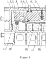
- Fig. 1 shows a section of a die for flanging according to the present invention.
- this element when it is called that one element is located “on” another element or is “connected” to another element etc., this element can be directly located on said another element or connected to said another element, or an intermediate element can be provided.
- Fig. 1 shows a die for flanging according to the present invention, said die comprising an upper die and a lower die.
- the upper die and the lower die cooperate with each other and are in the closed state.
- the upper die comprises an upper shoe plate 1 and a pressure plate 4, wherein the upper shoe plate 1 bears other members of the upper die.
- the pressure plate contacts with a workpiece 10 supported on the lower die and exerts pressure on the workpiece.
- the pressure plate 4 can be kept on said upper shoe plate.
- the upper shoe plate 1 and the pressure plate 4 can be made of metal.
- the pressure plate 4 is kept on the upper shoe plate 1 by means of a retaining screw bolt 9. A region, for instance, a region of 30mm to 40mm on the pressure plate 4 is vacated. In said region, the pressure plate 4 is connected with the upper shoe plate 1 via the retaining screw bolt 9 for keeping the pressure plate.
- the pressure plate 4 is provided with an opening, through which the retaining screw bolt 9 passes and is fixed onto the upper shoe plate.
- the retaining screw bolt 9's end away from the upper shoe plate is provided with a pad 8 for absorbing impaction forces generated in the stamping process when the pressure plate contacts with the workpiece.
- Said pad can be made of a cushion material, e.g. polyurethane.
- the pressure plate 4 is provided with an upper beating rod 7.
- Said upper beating rod 7 can be connected with a loading member located outside the die, so as to provide pressure for the pressure plate.
- the upper beating rod 7 is fixed onto the pressure plate via screws.
- a through hole is provided in the upper shoe plate 1.
- the upper beating rod 7 passes through the through hole to contact with the equipment's upper air cushion (not shown) to provide pressing force.
- a flanging insert 5 for flanging the workpiece is fixed to the upper shoe plate.
- the flanging insert 5 is fixed in the upper shoe plate through a screw. In the stamping process, the flanging insert forces the workpiece to form a flanged portion.
- the lower die comprises a lower shoe plate 12.
- a forming die 11 is fixed on the lower shoe plate 12.
- Said forming die is, for instance, fixed onto the lower shoe plate via a screw.
- the lower shoe plate and the forming die can be made of metal.
- the lower shoe plate 12 is provided with guide elements, such as guide plates 14, those have the function of making the upper die be guided during die closing.
- the guide plates are fixed, for instance, are fixed via screws, in the lower shoe plate 12.
- the number of the guide plates can be one or more.
- the lower shoe plate is provided with two guide plates in total. To be positioned precisely, said guide plates contact with the upper shoe plate 1 in the abutment manner, as shown in Fig. 1 .
- the upper shoe plate 1, the lower shoe plate 12 and the guide plates 14 form a die frame of the whole die.
- the pressure plate 4 is provided with a backing plate 2.
- An upper balance block 3 is supported on said backing plate 2.
- the upper balance block has a recessed portion that is, for instance, conical.
- the backing plate below the upper balance block has the function of adjusting height.
- the upper balance block cooperates with a lower balance block 13 arranged on the lower shoe plate 12.
- Said lower balance block has a shape, such as a conical shape, adapted to the recessed portion of the upper balance block.
- the upper balance block 3 and the lower balance block 13 are engaged together to cooperated with each other during die closing, so as to have functions of orientation and balancing pressure.
- a planar cushioning element 6 is fixed on the pressure plate 4.
- Said planar cushioning element is at least arranged in the pressure plate's region in contact with the workpiece.
- the planar cushioning element is provided in the region of flanging line. The said planar cushioning element transfers pressure of the pressure plate 4 onto the workpiece 10, so as to make the workpiece be pressed tightly, assure that the workpiece does not move any more, and simultaneously buffer impaction forces during blank pressing process.
- the cushioning element is a plate made of polyurethane.
- the experiments prove that the polyurethane material is in particular suitable for manufacturing the cushioning element in the present invention.
- the polyurethane having a thickness of 0.3mm-1.0mm is favorable from the aspect of cost, can realize the function of buffering sufficiently and simultaneously is thick enough for absorbing the generated scraps.
- the polyurethane cushioning element 6 has a blank pressing region in which the cushioning element has a width of 30mm-40mm and a thickness of 0.3mm to 1.0mm.
- the cushioning element further comprises a remaining region for fixation except for the blank pressing region. Said remaining region starting from the blank pressing region becomes gradually thicker, and a hole for passage of the screw is configured in said remaining region, such that the polyurethane cushioning element 6 can be secured on the pressure plate 4 by the screw.
- the cushioning element 6 has the function of blank pressing during die closing. Furthermore, to avoid bringing about unfavorable effect on the quality of the workpiece's surface, the screw does not contact with the workpiece 10 supported on the forming die.
- the polyurethane cushioning element is also fixed onto the pressure plate by means of adhesion. In the case of adhesion, it is only required to make the blank pressing region be provided with the planar cushioning element.
- a flanging process according to the present invention is described simply in the following paragraphs.
- the upper die and the lower die are divided.
- the workpiece 10 is placed on the forming die 11, the lower die is held stationary, and the upper die moves downwards relative to the lower die. Meanwhile, the pressure plate kept on the upper die also moves downwards.
- the polyurethane cushioning element arranged on the pressure plate contacts with the workpiece.
- the upper shoe plate of the upper die continues to move downwards together with the flanging insert arranged thereon.
- the upper beating rod 7 is gradually exposed from the upper shoe plate and contacts with the upper air cushion of the press machine, and then starts to transfer a blank pressing force that is transferred onto the polyurethane cushioning element 6 through the pressure plate 4.
- the retaining screw bolt moves downwards along the opening in the pressure plate.
- the pressure applied onto the workpiece becomes larger and larger due to the action of the pressure in the upper air cushion. Therefore, under the action of pressure, the cushioning element is gradually shrinked deformed to balance the blank pressing force of the blank pressing region and press the workpiece 10 tightly, and simultaneously compensate the uneven surface of the pressure plate 4.
- the flanging insert 5 contacts with the workpiece 10 gradually till completion of the flanging at last. After this, the upper die moves upward, the flanging insert 5 and the cushioning element 6 leave the workpiece gradually, such that its initial shapes are recovered.
Landscapes
- Engineering & Computer Science (AREA)
- Mechanical Engineering (AREA)
- Shaping Metal By Deep-Drawing, Or The Like (AREA)
- Presses And Accessory Devices Thereof (AREA)
- Moulds For Moulding Plastics Or The Like (AREA)
Claims (10)
- Matrize zum Anflanschen, umfassend eine obere Matrize, die beweglich ist, und eine untere Matrize, die stationär gehalten wird, wobei die obere Matrize mit einer Andruckplatte (4) zum Stanzen eines Werkstücks bereitgestellt ist, die untere Matrize mit einer Formmatrize (11) zum Tragen des Werkstücks bereitgestellt ist, wobei Dämpfungselement (6) mindestens in einem Blankpressbereich der Andruckplatte (4) zum festen Pressen des Werkstücks, das auf der Formmatrize (11) liegt, angeordnet ist, und das Dämpfungselement (6) aus Polyurethan hergestellt ist, wobei die obere Matrize eine obere Schuhplatte (1) aufweist, die andere Elemente der oberen Matrize trägt, und wobei das Dämpfungselement (6) in dem Bereich einer Anflanschlinie angeordnet ist, dadurch gekennzeichnet, dass das Dämpfungselement planar ist, und wobei ein Anflanscheinsatz (5) zum Anflanschen des Werkstücks an der oberen Schuhplatte durch eine Schraube befestigt ist, wobei in dem Stanzprozess der Anflanscheinsatz das Werkstück drängt, einen Flanschabschnitt entlang einer Flanschlinie zu bilden.
- Matrize nach Anspruch 1, dadurch gekennzeichnet, dass nur ein Teilbereich der Andruckplatte (4) mit dem planaren Dämpfungselement bereitgestellt ist und das Dämpfungselement einen Blankpressbereich umfasst, in dem das Dämpfungselement eine Breite von 30 mm bis 40 mm aufweist.
- Matrize nach Anspruch 1 oder 2, dadurch gekennzeichnet, dass das Dämpfungselement (6) an der Andruckplatte (4) durch eine Schraube oder Adhäsion befestigt ist.
- Matrize nach einem der Ansprüche 1 bis 3, dadurch gekennzeichnet, dass die Härte des Dämpfungselements (6) größer als Shore Härte 80 ist.
- Matrize nach einem der Ansprüche 1 bis 4, dadurch gekennzeichnet, dass das Dämpfungselement (6) eine Dicke von 0,3 mm bis 1,0 mm aufweist.
- Matrize nach einem der Ansprüche 1 bis 5, dadurch gekennzeichnet, dass die untere Matrize eine untere Schuhplatte (12) aufweist, die Andruckplatte (4) mit einer Rückenplatte (2) bereitgestellt ist, auf der ein oberer Ausgleichsblock (3) gehalten wird, und der obere Ausgleichsblock mit einem unteren Ausgleichsblock (13) auf der unteren Schuhplatte (12) zusammenwirkt.
- Matrize nach Anspruch 6, dadurch gekennzeichnet, dass der obere Ausgleichsblock (3) einen bevorzugt konischen vertieften Abschnitt aufweist und der untere Ausgleichsblock (13) eine bevorzugt konische Form aufweist, die an den vertieften Abschnitt angepasst ist.
- Matrize nach Anspruch 6, dadurch gekennzeichnet, dass die untere Schuhplatte (12) mit Führungselementen (14) bereitgestellt ist, die bevorzugt Führungsplatten sind" und die Führungselemente mit der oberen Schuhplatte (1) für ein präzises Zusammenwirken der oberen Schuhplatte (1) und der unteren Schuhplatte (12) bevorzugt in anliegender Weise in Kontakt sind.
- Matrize nach Anspruch 6, dadurch gekennzeichnet, dass die Andruckplatte (4) durch einen Halterungsschraubbolzen (9) in der oberen Schuhplatte gehalten wird und der Halterungsschraubbolzen (9) mit einem Belag (8) aus Polyurethan bereitgestellt ist.
- Matrize nach einem der Ansprüche 1 bis 9, dadurch gekennzeichnet, dass die Andruckplatte (4) mit einer oberen Schlagstange (7) zur Verbindung mit einem Lastelement bereitgestellt ist, das sich außerhalb der Matrize befindet, und die obere Schlagstange an der Andruckplatte durch Schrauben befestigt ist.
Applications Claiming Priority (1)
| Application Number | Priority Date | Filing Date | Title |
|---|---|---|---|
| CN201711391625.5A CN109940093A (zh) | 2017-12-21 | 2017-12-21 | 模具 |
Publications (2)
| Publication Number | Publication Date |
|---|---|
| EP3501682A1 EP3501682A1 (de) | 2019-06-26 |
| EP3501682B1 true EP3501682B1 (de) | 2021-01-20 |
Family
ID=62152418
Family Applications (1)
| Application Number | Title | Priority Date | Filing Date |
|---|---|---|---|
| EP18171769.5A Active EP3501682B1 (de) | 2017-12-21 | 2018-05-11 | Matrize |
Country Status (2)
| Country | Link |
|---|---|
| EP (1) | EP3501682B1 (de) |
| CN (1) | CN109940093A (de) |
Families Citing this family (4)
| Publication number | Priority date | Publication date | Assignee | Title |
|---|---|---|---|---|
| CN112775255B (zh) * | 2020-12-24 | 2022-12-06 | 南京京力汽车零部件有限公司 | 一种冲压拉延模内压边成型装置及其使用方法 |
| CN115488234A (zh) * | 2022-08-19 | 2022-12-20 | 瑞鹄汽车模具股份有限公司 | 一种减少门把手a面变形的翻边模具机构 |
| CN116408392B (zh) * | 2023-03-10 | 2025-09-09 | 中国第一汽车股份有限公司 | 一种齿轮驱动电动调节平衡块装置 |
| CN117181895A (zh) * | 2023-10-24 | 2023-12-08 | 江西江铃底盘股份有限公司 | 一种汽车后桥非金属材料挡圈落料-冲孔复合模具及其加工工艺 |
Family Cites Families (9)
| Publication number | Priority date | Publication date | Assignee | Title |
|---|---|---|---|---|
| DE4235972A1 (de) * | 1992-10-26 | 1994-04-28 | Pass Anlagenbau Gmbh | Schneid-Werkzeug, insbesondere für Stanz- und Nibbelautomaten |
| JP2001047147A (ja) * | 1999-08-11 | 2001-02-20 | Mitsui High Tec Inc | 金型装置 |
| CN202052866U (zh) | 2011-05-11 | 2011-11-30 | 上海众达汽车冲压件有限公司 | 一种汽车尾灯支架的冷冲压翻边成形模具 |
| CN202498129U (zh) * | 2012-03-22 | 2012-10-24 | 成都槟果科技有限公司 | 简易复合冲压模 |
| CN104353730B (zh) | 2014-10-27 | 2016-08-24 | 沈阳黎明航空发动机(集团)有限责任公司 | 一种双层环形件内翻边模具及翻边工艺 |
| CN204194600U (zh) * | 2014-11-06 | 2015-03-11 | 上海众达汽车冲压件有限公司 | 一种汽车嵌入件的翻边成形模具 |
| JP6059291B2 (ja) * | 2015-06-03 | 2017-01-11 | アイダエンジニアリング株式会社 | プレス機械のダイクッション装置 |
| TWI599476B (zh) * | 2015-06-16 | 2017-09-21 | National Kaohsiung First Univ Of Science And Technology | Molding mold with rubber pressure plate |
| CN205732472U (zh) * | 2016-05-17 | 2016-11-30 | 江苏未来轨道交通装备股份有限公司 | 一种公用自行车车桩用钣金件冲压模具 |
-
2017
- 2017-12-21 CN CN201711391625.5A patent/CN109940093A/zh active Pending
-
2018
- 2018-05-11 EP EP18171769.5A patent/EP3501682B1/de active Active
Non-Patent Citations (1)
| Title |
|---|
| None * |
Also Published As
| Publication number | Publication date |
|---|---|
| EP3501682A1 (de) | 2019-06-26 |
| CN109940093A (zh) | 2019-06-28 |
Similar Documents
| Publication | Publication Date | Title |
|---|---|---|
| EP3501682B1 (de) | Matrize | |
| CN101716631B (zh) | 一种汽车线束连续冲模模具 | |
| CN104368681B (zh) | 斜楔机构 | |
| JP4090028B2 (ja) | 薄鋼板のプレス成形用金型装置 | |
| KR102446094B1 (ko) | 상부 패드와 하부 펀치를 가공하여 내부지지 방식으로 측방향 하중을 지지하는 벤딩 프레스금형 | |
| JP2017113782A (ja) | ホットプレス装置、及びホットプレス成形方法 | |
| CN102909242A (zh) | 一种钣金冲压模用90度折弯机构 | |
| CN201419208Y (zh) | 可重构多种形状的冲压模具 | |
| CN202893911U (zh) | 一种钣金冲压模用90度折弯机构 | |
| MX2021008959A (es) | Metodo de formacion por prensado y aparato de prensado. | |
| JP2006116554A (ja) | 形状凍結性に優れたプレス金型 | |
| CN201329391Y (zh) | 一种窄槽旋转体零件冲压二次拉深模具 | |
| JP2016002590A (ja) | 曲げ金型 | |
| CN201720294U (zh) | 双曲面折弯机构 | |
| CN205309079U (zh) | 一种防工件磨损的中铰链垫片弯曲模母模组件 | |
| JP2020157325A (ja) | プレス成型装置 | |
| CN204262156U (zh) | 斜楔机构 | |
| KR20190043672A (ko) | 성형 장치 | |
| CN207325738U (zh) | 铁路客车车辆用高磷闸瓦瓦背的复合成型模具 | |
| CN107127224A (zh) | 一种压铸工件检修系统 | |
| CN102989854B (zh) | 汽车l型冲压件翻边角度不到位和翻边面不平的整改方法 | |
| CN211660922U (zh) | 一种模具侧推结构 | |
| CN218487016U (zh) | 一种带包角铆接式高温承载舟一体成型模具 | |
| CN204867068U (zh) | 同步整形冲压模具 | |
| JP7069998B2 (ja) | 凹状エンボス部を有する自動車外板パネルの製造方法およびプレス成形装置 |
Legal Events
| Date | Code | Title | Description |
|---|---|---|---|
| PUAI | Public reference made under article 153(3) epc to a published international application that has entered the european phase |
Free format text: ORIGINAL CODE: 0009012 |
|
| STAA | Information on the status of an ep patent application or granted ep patent |
Free format text: STATUS: THE APPLICATION HAS BEEN PUBLISHED |
|
| AK | Designated contracting states |
Kind code of ref document: A1 Designated state(s): AL AT BE BG CH CY CZ DE DK EE ES FI FR GB GR HR HU IE IS IT LI LT LU LV MC MK MT NL NO PL PT RO RS SE SI SK SM TR |
|
| AX | Request for extension of the european patent |
Extension state: BA ME |
|
| STAA | Information on the status of an ep patent application or granted ep patent |
Free format text: STATUS: REQUEST FOR EXAMINATION WAS MADE |
|
| 17P | Request for examination filed |
Effective date: 20191216 |
|
| RBV | Designated contracting states (corrected) |
Designated state(s): AL AT BE BG CH CY CZ DE DK EE ES FI FR GB GR HR HU IE IS IT LI LT LU LV MC MK MT NL NO PL PT RO RS SE SI SK SM TR |
|
| STAA | Information on the status of an ep patent application or granted ep patent |
Free format text: STATUS: EXAMINATION IS IN PROGRESS |
|
| 17Q | First examination report despatched |
Effective date: 20200323 |
|
| GRAP | Despatch of communication of intention to grant a patent |
Free format text: ORIGINAL CODE: EPIDOSNIGR1 |
|
| STAA | Information on the status of an ep patent application or granted ep patent |
Free format text: STATUS: GRANT OF PATENT IS INTENDED |
|
| INTG | Intention to grant announced |
Effective date: 20201021 |
|
| GRAS | Grant fee paid |
Free format text: ORIGINAL CODE: EPIDOSNIGR3 |
|
| GRAA | (expected) grant |
Free format text: ORIGINAL CODE: 0009210 |
|
| STAA | Information on the status of an ep patent application or granted ep patent |
Free format text: STATUS: THE PATENT HAS BEEN GRANTED |
|
| AK | Designated contracting states |
Kind code of ref document: B1 Designated state(s): AL AT BE BG CH CY CZ DE DK EE ES FI FR GB GR HR HU IE IS IT LI LT LU LV MC MK MT NL NO PL PT RO RS SE SI SK SM TR |
|
| REG | Reference to a national code |
Ref country code: GB Ref legal event code: FG4D |
|
| REG | Reference to a national code |
Ref country code: CH Ref legal event code: EP |
|
| REG | Reference to a national code |
Ref country code: DE Ref legal event code: R096 Ref document number: 602018011960 Country of ref document: DE |
|
| REG | Reference to a national code |
Ref country code: AT Ref legal event code: REF Ref document number: 1355924 Country of ref document: AT Kind code of ref document: T Effective date: 20210215 |
|
| REG | Reference to a national code |
Ref country code: IE Ref legal event code: FG4D |
|
| REG | Reference to a national code |
Ref country code: NL Ref legal event code: MP Effective date: 20210120 |
|
| REG | Reference to a national code |
Ref country code: LT Ref legal event code: MG9D |
|
| REG | Reference to a national code |
Ref country code: AT Ref legal event code: MK05 Ref document number: 1355924 Country of ref document: AT Kind code of ref document: T Effective date: 20210120 |
|
| PG25 | Lapsed in a contracting state [announced via postgrant information from national office to epo] |
Ref country code: LT Free format text: LAPSE BECAUSE OF FAILURE TO SUBMIT A TRANSLATION OF THE DESCRIPTION OR TO PAY THE FEE WITHIN THE PRESCRIBED TIME-LIMIT Effective date: 20210120 Ref country code: NO Free format text: LAPSE BECAUSE OF FAILURE TO SUBMIT A TRANSLATION OF THE DESCRIPTION OR TO PAY THE FEE WITHIN THE PRESCRIBED TIME-LIMIT Effective date: 20210420 Ref country code: PT Free format text: LAPSE BECAUSE OF FAILURE TO SUBMIT A TRANSLATION OF THE DESCRIPTION OR TO PAY THE FEE WITHIN THE PRESCRIBED TIME-LIMIT Effective date: 20210520 Ref country code: HR Free format text: LAPSE BECAUSE OF FAILURE TO SUBMIT A TRANSLATION OF THE DESCRIPTION OR TO PAY THE FEE WITHIN THE PRESCRIBED TIME-LIMIT Effective date: 20210120 Ref country code: FI Free format text: LAPSE BECAUSE OF FAILURE TO SUBMIT A TRANSLATION OF THE DESCRIPTION OR TO PAY THE FEE WITHIN THE PRESCRIBED TIME-LIMIT Effective date: 20210120 Ref country code: GR Free format text: LAPSE BECAUSE OF FAILURE TO SUBMIT A TRANSLATION OF THE DESCRIPTION OR TO PAY THE FEE WITHIN THE PRESCRIBED TIME-LIMIT Effective date: 20210421 Ref country code: BG Free format text: LAPSE BECAUSE OF FAILURE TO SUBMIT A TRANSLATION OF THE DESCRIPTION OR TO PAY THE FEE WITHIN THE PRESCRIBED TIME-LIMIT Effective date: 20210420 |
|
| PG25 | Lapsed in a contracting state [announced via postgrant information from national office to epo] |
Ref country code: PL Free format text: LAPSE BECAUSE OF FAILURE TO SUBMIT A TRANSLATION OF THE DESCRIPTION OR TO PAY THE FEE WITHIN THE PRESCRIBED TIME-LIMIT Effective date: 20210120 Ref country code: LV Free format text: LAPSE BECAUSE OF FAILURE TO SUBMIT A TRANSLATION OF THE DESCRIPTION OR TO PAY THE FEE WITHIN THE PRESCRIBED TIME-LIMIT Effective date: 20210120 Ref country code: RS Free format text: LAPSE BECAUSE OF FAILURE TO SUBMIT A TRANSLATION OF THE DESCRIPTION OR TO PAY THE FEE WITHIN THE PRESCRIBED TIME-LIMIT Effective date: 20210120 Ref country code: AT Free format text: LAPSE BECAUSE OF FAILURE TO SUBMIT A TRANSLATION OF THE DESCRIPTION OR TO PAY THE FEE WITHIN THE PRESCRIBED TIME-LIMIT Effective date: 20210120 Ref country code: SE Free format text: LAPSE BECAUSE OF FAILURE TO SUBMIT A TRANSLATION OF THE DESCRIPTION OR TO PAY THE FEE WITHIN THE PRESCRIBED TIME-LIMIT Effective date: 20210120 |
|
| PG25 | Lapsed in a contracting state [announced via postgrant information from national office to epo] |
Ref country code: IS Free format text: LAPSE BECAUSE OF FAILURE TO SUBMIT A TRANSLATION OF THE DESCRIPTION OR TO PAY THE FEE WITHIN THE PRESCRIBED TIME-LIMIT Effective date: 20210520 |
|
| REG | Reference to a national code |
Ref country code: DE Ref legal event code: R097 Ref document number: 602018011960 Country of ref document: DE |
|
| PG25 | Lapsed in a contracting state [announced via postgrant information from national office to epo] |
Ref country code: CZ Free format text: LAPSE BECAUSE OF FAILURE TO SUBMIT A TRANSLATION OF THE DESCRIPTION OR TO PAY THE FEE WITHIN THE PRESCRIBED TIME-LIMIT Effective date: 20210120 Ref country code: EE Free format text: LAPSE BECAUSE OF FAILURE TO SUBMIT A TRANSLATION OF THE DESCRIPTION OR TO PAY THE FEE WITHIN THE PRESCRIBED TIME-LIMIT Effective date: 20210120 Ref country code: SM Free format text: LAPSE BECAUSE OF FAILURE TO SUBMIT A TRANSLATION OF THE DESCRIPTION OR TO PAY THE FEE WITHIN THE PRESCRIBED TIME-LIMIT Effective date: 20210120 |
|
| PLBE | No opposition filed within time limit |
Free format text: ORIGINAL CODE: 0009261 |
|
| STAA | Information on the status of an ep patent application or granted ep patent |
Free format text: STATUS: NO OPPOSITION FILED WITHIN TIME LIMIT |
|
| PG25 | Lapsed in a contracting state [announced via postgrant information from national office to epo] |
Ref country code: RO Free format text: LAPSE BECAUSE OF FAILURE TO SUBMIT A TRANSLATION OF THE DESCRIPTION OR TO PAY THE FEE WITHIN THE PRESCRIBED TIME-LIMIT Effective date: 20210120 Ref country code: DK Free format text: LAPSE BECAUSE OF FAILURE TO SUBMIT A TRANSLATION OF THE DESCRIPTION OR TO PAY THE FEE WITHIN THE PRESCRIBED TIME-LIMIT Effective date: 20210120 Ref country code: SK Free format text: LAPSE BECAUSE OF FAILURE TO SUBMIT A TRANSLATION OF THE DESCRIPTION OR TO PAY THE FEE WITHIN THE PRESCRIBED TIME-LIMIT Effective date: 20210120 |
|
| 26N | No opposition filed |
Effective date: 20211021 |
|
| REG | Reference to a national code |
Ref country code: CH Ref legal event code: PL |
|
| PG25 | Lapsed in a contracting state [announced via postgrant information from national office to epo] |
Ref country code: ES Free format text: LAPSE BECAUSE OF FAILURE TO SUBMIT A TRANSLATION OF THE DESCRIPTION OR TO PAY THE FEE WITHIN THE PRESCRIBED TIME-LIMIT Effective date: 20210120 Ref country code: LI Free format text: LAPSE BECAUSE OF NON-PAYMENT OF DUE FEES Effective date: 20210531 Ref country code: LU Free format text: LAPSE BECAUSE OF NON-PAYMENT OF DUE FEES Effective date: 20210511 Ref country code: MC Free format text: LAPSE BECAUSE OF FAILURE TO SUBMIT A TRANSLATION OF THE DESCRIPTION OR TO PAY THE FEE WITHIN THE PRESCRIBED TIME-LIMIT Effective date: 20210120 Ref country code: AL Free format text: LAPSE BECAUSE OF FAILURE TO SUBMIT A TRANSLATION OF THE DESCRIPTION OR TO PAY THE FEE WITHIN THE PRESCRIBED TIME-LIMIT Effective date: 20210120 Ref country code: CH Free format text: LAPSE BECAUSE OF NON-PAYMENT OF DUE FEES Effective date: 20210531 |
|
| REG | Reference to a national code |
Ref country code: BE Ref legal event code: MM Effective date: 20210531 |
|
| PG25 | Lapsed in a contracting state [announced via postgrant information from national office to epo] |
Ref country code: SI Free format text: LAPSE BECAUSE OF FAILURE TO SUBMIT A TRANSLATION OF THE DESCRIPTION OR TO PAY THE FEE WITHIN THE PRESCRIBED TIME-LIMIT Effective date: 20210120 |
|
| PG25 | Lapsed in a contracting state [announced via postgrant information from national office to epo] |
Ref country code: IT Free format text: LAPSE BECAUSE OF FAILURE TO SUBMIT A TRANSLATION OF THE DESCRIPTION OR TO PAY THE FEE WITHIN THE PRESCRIBED TIME-LIMIT Effective date: 20210120 Ref country code: IE Free format text: LAPSE BECAUSE OF NON-PAYMENT OF DUE FEES Effective date: 20210511 |
|
| PG25 | Lapsed in a contracting state [announced via postgrant information from national office to epo] |
Ref country code: IS Free format text: LAPSE BECAUSE OF FAILURE TO SUBMIT A TRANSLATION OF THE DESCRIPTION OR TO PAY THE FEE WITHIN THE PRESCRIBED TIME-LIMIT Effective date: 20210520 Ref country code: FR Free format text: LAPSE BECAUSE OF NON-PAYMENT OF DUE FEES Effective date: 20210531 |
|
| PG25 | Lapsed in a contracting state [announced via postgrant information from national office to epo] |
Ref country code: BE Free format text: LAPSE BECAUSE OF NON-PAYMENT OF DUE FEES Effective date: 20210531 |
|
| GBPC | Gb: european patent ceased through non-payment of renewal fee |
Effective date: 20220511 |
|
| PG25 | Lapsed in a contracting state [announced via postgrant information from national office to epo] |
Ref country code: GB Free format text: LAPSE BECAUSE OF NON-PAYMENT OF DUE FEES Effective date: 20220511 |
|
| PG25 | Lapsed in a contracting state [announced via postgrant information from national office to epo] |
Ref country code: NL Free format text: LAPSE BECAUSE OF NON-PAYMENT OF DUE FEES Effective date: 20210120 Ref country code: CY Free format text: LAPSE BECAUSE OF FAILURE TO SUBMIT A TRANSLATION OF THE DESCRIPTION OR TO PAY THE FEE WITHIN THE PRESCRIBED TIME-LIMIT Effective date: 20210120 |
|
| PG25 | Lapsed in a contracting state [announced via postgrant information from national office to epo] |
Ref country code: HU Free format text: LAPSE BECAUSE OF FAILURE TO SUBMIT A TRANSLATION OF THE DESCRIPTION OR TO PAY THE FEE WITHIN THE PRESCRIBED TIME-LIMIT; INVALID AB INITIO Effective date: 20180511 |
|
| PG25 | Lapsed in a contracting state [announced via postgrant information from national office to epo] |
Ref country code: MK Free format text: LAPSE BECAUSE OF FAILURE TO SUBMIT A TRANSLATION OF THE DESCRIPTION OR TO PAY THE FEE WITHIN THE PRESCRIBED TIME-LIMIT Effective date: 20210120 |
|
| PG25 | Lapsed in a contracting state [announced via postgrant information from national office to epo] |
Ref country code: MT Free format text: LAPSE BECAUSE OF FAILURE TO SUBMIT A TRANSLATION OF THE DESCRIPTION OR TO PAY THE FEE WITHIN THE PRESCRIBED TIME-LIMIT Effective date: 20210120 |
|
| PGFP | Annual fee paid to national office [announced via postgrant information from national office to epo] |
Ref country code: DE Payment date: 20250527 Year of fee payment: 8 |
|
| PG25 | Lapsed in a contracting state [announced via postgrant information from national office to epo] |
Ref country code: TR Free format text: LAPSE BECAUSE OF FAILURE TO SUBMIT A TRANSLATION OF THE DESCRIPTION OR TO PAY THE FEE WITHIN THE PRESCRIBED TIME-LIMIT Effective date: 20210120 |