EP3501648A1 - Katalytisch aktives partikelfilter - Google Patents
Katalytisch aktives partikelfilter Download PDFInfo
- Publication number
- EP3501648A1 EP3501648A1 EP17208615.9A EP17208615A EP3501648A1 EP 3501648 A1 EP3501648 A1 EP 3501648A1 EP 17208615 A EP17208615 A EP 17208615A EP 3501648 A1 EP3501648 A1 EP 3501648A1
- Authority
- EP
- European Patent Office
- Prior art keywords
- oxide
- coating
- wall
- oxygen storage
- rhodium
- Prior art date
- Legal status (The legal status is an assumption and is not a legal conclusion. Google has not performed a legal analysis and makes no representation as to the accuracy of the status listed.)
- Granted
Links
- 239000002245 particle Substances 0.000 title claims abstract description 29
- 238000000576 coating method Methods 0.000 claims abstract description 117
- 239000011248 coating agent Substances 0.000 claims abstract description 90
- MRELNEQAGSRDBK-UHFFFAOYSA-N lanthanum(3+);oxygen(2-) Chemical compound [O-2].[O-2].[O-2].[La+3].[La+3] MRELNEQAGSRDBK-UHFFFAOYSA-N 0.000 claims description 114
- KDLHZDBZIXYQEI-UHFFFAOYSA-N Palladium Chemical compound [Pd] KDLHZDBZIXYQEI-UHFFFAOYSA-N 0.000 claims description 74
- QVGXLLKOCUKJST-UHFFFAOYSA-N atomic oxygen Chemical compound [O] QVGXLLKOCUKJST-UHFFFAOYSA-N 0.000 claims description 73
- 239000001301 oxygen Substances 0.000 claims description 73
- 229910052760 oxygen Inorganic materials 0.000 claims description 73
- 238000003860 storage Methods 0.000 claims description 73
- MCMNRKCIXSYSNV-UHFFFAOYSA-N Zirconium dioxide Chemical compound O=[Zr]=O MCMNRKCIXSYSNV-UHFFFAOYSA-N 0.000 claims description 68
- PNEYBMLMFCGWSK-UHFFFAOYSA-N aluminium oxide Inorganic materials [O-2].[O-2].[O-2].[Al+3].[Al+3] PNEYBMLMFCGWSK-UHFFFAOYSA-N 0.000 claims description 39
- 229910052703 rhodium Inorganic materials 0.000 claims description 38
- 239000010948 rhodium Substances 0.000 claims description 38
- MHOVAHRLVXNVSD-UHFFFAOYSA-N rhodium atom Chemical compound [Rh] MHOVAHRLVXNVSD-UHFFFAOYSA-N 0.000 claims description 38
- 229910052763 palladium Inorganic materials 0.000 claims description 37
- CETPSERCERDGAM-UHFFFAOYSA-N ceric oxide Chemical compound O=[Ce]=O CETPSERCERDGAM-UHFFFAOYSA-N 0.000 claims description 34
- 229910000422 cerium(IV) oxide Inorganic materials 0.000 claims description 34
- 239000007789 gas Substances 0.000 claims description 27
- 229910000510 noble metal Inorganic materials 0.000 claims description 27
- MWUXSHHQAYIFBG-UHFFFAOYSA-N nitrogen oxide Inorganic materials O=[N] MWUXSHHQAYIFBG-UHFFFAOYSA-N 0.000 claims description 21
- RUDFQVOCFDJEEF-UHFFFAOYSA-N yttrium(III) oxide Inorganic materials [O-2].[O-2].[O-2].[Y+3].[Y+3] RUDFQVOCFDJEEF-UHFFFAOYSA-N 0.000 claims description 19
- MMKQUGHLEMYQSG-UHFFFAOYSA-N oxygen(2-);praseodymium(3+) Chemical compound [O-2].[O-2].[O-2].[Pr+3].[Pr+3] MMKQUGHLEMYQSG-UHFFFAOYSA-N 0.000 claims description 15
- 229910003447 praseodymium oxide Inorganic materials 0.000 claims description 15
- 239000000446 fuel Substances 0.000 claims description 12
- SIWVEOZUMHYXCS-UHFFFAOYSA-N oxo(oxoyttriooxy)yttrium Chemical compound O=[Y]O[Y]=O SIWVEOZUMHYXCS-UHFFFAOYSA-N 0.000 claims description 12
- 238000002485 combustion reaction Methods 0.000 claims description 11
- 239000000203 mixture Substances 0.000 claims description 11
- 229910052761 rare earth metal Inorganic materials 0.000 claims description 10
- 229910052684 Cerium Inorganic materials 0.000 claims description 9
- 239000000463 material Substances 0.000 claims description 9
- 150000002910 rare earth metals Chemical class 0.000 claims description 9
- QCWXUUIWCKQGHC-UHFFFAOYSA-N Zirconium Chemical compound [Zr] QCWXUUIWCKQGHC-UHFFFAOYSA-N 0.000 claims description 8
- 229910052726 zirconium Inorganic materials 0.000 claims description 8
- UGFAIRIUMAVXCW-UHFFFAOYSA-N Carbon monoxide Chemical compound [O+]#[C-] UGFAIRIUMAVXCW-UHFFFAOYSA-N 0.000 claims description 7
- 229910002091 carbon monoxide Inorganic materials 0.000 claims description 7
- 229930195733 hydrocarbon Natural products 0.000 claims description 7
- 150000002430 hydrocarbons Chemical class 0.000 claims description 7
- PLDDOISOJJCEMH-UHFFFAOYSA-N neodymium(3+);oxygen(2-) Chemical compound [O-2].[O-2].[O-2].[Nd+3].[Nd+3] PLDDOISOJJCEMH-UHFFFAOYSA-N 0.000 claims description 6
- 229910001404 rare earth metal oxide Inorganic materials 0.000 claims description 6
- GWEVSGVZZGPLCZ-UHFFFAOYSA-N Titan oxide Chemical compound O=[Ti]=O GWEVSGVZZGPLCZ-UHFFFAOYSA-N 0.000 claims description 5
- VYPSYNLAJGMNEJ-UHFFFAOYSA-N Silicium dioxide Chemical compound O=[Si]=O VYPSYNLAJGMNEJ-UHFFFAOYSA-N 0.000 claims description 4
- 229910000420 cerium oxide Inorganic materials 0.000 claims description 4
- BMMGVYCKOGBVEV-UHFFFAOYSA-N oxo(oxoceriooxy)cerium Chemical compound [Ce]=O.O=[Ce]=O BMMGVYCKOGBVEV-UHFFFAOYSA-N 0.000 claims description 4
- BASFCYQUMIYNBI-UHFFFAOYSA-N platinum Chemical compound [Pt] BASFCYQUMIYNBI-UHFFFAOYSA-N 0.000 claims description 4
- 238000000034 method Methods 0.000 claims description 3
- RVTZCBVAJQQJTK-UHFFFAOYSA-N oxygen(2-);zirconium(4+) Chemical compound [O-2].[O-2].[Zr+4] RVTZCBVAJQQJTK-UHFFFAOYSA-N 0.000 claims description 3
- 229910001928 zirconium oxide Inorganic materials 0.000 claims description 3
- 229910044991 metal oxide Inorganic materials 0.000 claims description 2
- 150000004706 metal oxides Chemical class 0.000 claims description 2
- 229910052697 platinum Inorganic materials 0.000 claims description 2
- 229910001954 samarium oxide Inorganic materials 0.000 claims description 2
- 229940075630 samarium oxide Drugs 0.000 claims description 2
- FKTOIHSPIPYAPE-UHFFFAOYSA-N samarium(iii) oxide Chemical compound [O-2].[O-2].[O-2].[Sm+3].[Sm+3] FKTOIHSPIPYAPE-UHFFFAOYSA-N 0.000 claims description 2
- 239000000377 silicon dioxide Substances 0.000 claims description 2
- GWXLDORMOJMVQZ-UHFFFAOYSA-N cerium Chemical compound [Ce] GWXLDORMOJMVQZ-UHFFFAOYSA-N 0.000 claims 3
- 239000013618 particulate matter Substances 0.000 claims 2
- 238000011068 loading method Methods 0.000 description 38
- 239000000725 suspension Substances 0.000 description 29
- 239000000758 substrate Substances 0.000 description 27
- GPNDARIEYHPYAY-UHFFFAOYSA-N palladium(ii) nitrate Chemical compound [Pd+2].[O-][N+]([O-])=O.[O-][N+]([O-])=O GPNDARIEYHPYAY-UHFFFAOYSA-N 0.000 description 13
- VXNYVYJABGOSBX-UHFFFAOYSA-N rhodium(3+);trinitrate Chemical compound [Rh+3].[O-][N+]([O-])=O.[O-][N+]([O-])=O.[O-][N+]([O-])=O VXNYVYJABGOSBX-UHFFFAOYSA-N 0.000 description 13
- 238000003756 stirring Methods 0.000 description 13
- XLYOFNOQVPJJNP-UHFFFAOYSA-N water Substances O XLYOFNOQVPJJNP-UHFFFAOYSA-N 0.000 description 13
- 238000006243 chemical reaction Methods 0.000 description 11
- 230000032683 aging Effects 0.000 description 9
- 239000003054 catalyst Substances 0.000 description 8
- 239000011148 porous material Substances 0.000 description 8
- 230000007306 turnover Effects 0.000 description 7
- ZMIGMASIKSOYAM-UHFFFAOYSA-N cerium Chemical compound [Ce][Ce][Ce][Ce][Ce][Ce][Ce][Ce][Ce][Ce][Ce][Ce][Ce][Ce][Ce][Ce][Ce][Ce][Ce][Ce][Ce][Ce][Ce][Ce][Ce][Ce][Ce][Ce][Ce][Ce][Ce][Ce][Ce][Ce][Ce][Ce][Ce][Ce] ZMIGMASIKSOYAM-UHFFFAOYSA-N 0.000 description 6
- 239000011149 active material Substances 0.000 description 4
- QVQLCTNNEUAWMS-UHFFFAOYSA-N barium oxide Chemical compound [Ba]=O QVQLCTNNEUAWMS-UHFFFAOYSA-N 0.000 description 4
- TZCXTZWJZNENPQ-UHFFFAOYSA-L barium sulfate Chemical compound [Ba+2].[O-]S([O-])(=O)=O TZCXTZWJZNENPQ-UHFFFAOYSA-L 0.000 description 4
- 230000003197 catalytic effect Effects 0.000 description 4
- IATRAKWUXMZMIY-UHFFFAOYSA-N strontium oxide Chemical compound [O-2].[Sr+2] IATRAKWUXMZMIY-UHFFFAOYSA-N 0.000 description 4
- 238000012512 characterization method Methods 0.000 description 3
- 230000000052 comparative effect Effects 0.000 description 3
- 229910052746 lanthanum Inorganic materials 0.000 description 3
- FZLIPJUXYLNCLC-UHFFFAOYSA-N lanthanum atom Chemical compound [La] FZLIPJUXYLNCLC-UHFFFAOYSA-N 0.000 description 3
- 239000010970 precious metal Substances 0.000 description 3
- 238000000746 purification Methods 0.000 description 3
- 238000011144 upstream manufacturing Methods 0.000 description 3
- 229910000505 Al2TiO5 Inorganic materials 0.000 description 2
- 239000000654 additive Substances 0.000 description 2
- 239000012876 carrier material Substances 0.000 description 2
- 229910052878 cordierite Inorganic materials 0.000 description 2
- JSKIRARMQDRGJZ-UHFFFAOYSA-N dimagnesium dioxido-bis[(1-oxido-3-oxo-2,4,6,8,9-pentaoxa-1,3-disila-5,7-dialuminabicyclo[3.3.1]nonan-7-yl)oxy]silane Chemical compound [Mg++].[Mg++].[O-][Si]([O-])(O[Al]1O[Al]2O[Si](=O)O[Si]([O-])(O1)O2)O[Al]1O[Al]2O[Si](=O)O[Si]([O-])(O1)O2 JSKIRARMQDRGJZ-UHFFFAOYSA-N 0.000 description 2
- 238000009826 distribution Methods 0.000 description 2
- 239000003344 environmental pollutant Substances 0.000 description 2
- 238000004519 manufacturing process Methods 0.000 description 2
- TWNQGVIAIRXVLR-UHFFFAOYSA-N oxo(oxoalumanyloxy)alumane Chemical compound O=[Al]O[Al]=O TWNQGVIAIRXVLR-UHFFFAOYSA-N 0.000 description 2
- 231100000719 pollutant Toxicity 0.000 description 2
- AABBHSMFGKYLKE-SNAWJCMRSA-N propan-2-yl (e)-but-2-enoate Chemical compound C\C=C\C(=O)OC(C)C AABBHSMFGKYLKE-SNAWJCMRSA-N 0.000 description 2
- 230000000717 retained effect Effects 0.000 description 2
- HBMJWWWQQXIZIP-UHFFFAOYSA-N silicon carbide Chemical compound [Si+]#[C-] HBMJWWWQQXIZIP-UHFFFAOYSA-N 0.000 description 2
- 229910010271 silicon carbide Inorganic materials 0.000 description 2
- 239000004071 soot Substances 0.000 description 2
- 229910021193 La 2 O 3 Inorganic materials 0.000 description 1
- 229910021536 Zeolite Inorganic materials 0.000 description 1
- AZDRQVAHHNSJOQ-UHFFFAOYSA-N alumane Chemical class [AlH3] AZDRQVAHHNSJOQ-UHFFFAOYSA-N 0.000 description 1
- 239000011230 binding agent Substances 0.000 description 1
- 238000001354 calcination Methods 0.000 description 1
- 229910010293 ceramic material Inorganic materials 0.000 description 1
- 150000001875 compounds Chemical class 0.000 description 1
- 239000000470 constituent Substances 0.000 description 1
- 238000007796 conventional method Methods 0.000 description 1
- 239000013078 crystal Substances 0.000 description 1
- HNPSIPDUKPIQMN-UHFFFAOYSA-N dioxosilane;oxo(oxoalumanyloxy)alumane Chemical compound O=[Si]=O.O=[Al]O[Al]=O HNPSIPDUKPIQMN-UHFFFAOYSA-N 0.000 description 1
- 238000003618 dip coating Methods 0.000 description 1
- 238000001914 filtration Methods 0.000 description 1
- 239000010419 fine particle Substances 0.000 description 1
- 239000004615 ingredient Substances 0.000 description 1
- 239000002808 molecular sieve Substances 0.000 description 1
- 239000006069 physical mixture Substances 0.000 description 1
- -1 rare earth compounds Chemical class 0.000 description 1
- URGAHOPLAPQHLN-UHFFFAOYSA-N sodium aluminosilicate Chemical compound [Na+].[Al+3].[O-][Si]([O-])=O.[O-][Si]([O-])=O URGAHOPLAPQHLN-UHFFFAOYSA-N 0.000 description 1
- OGIDPMRJRNCKJF-UHFFFAOYSA-N titanium oxide Inorganic materials [Ti]=O OGIDPMRJRNCKJF-UHFFFAOYSA-N 0.000 description 1
- 239000010457 zeolite Substances 0.000 description 1
Images
Classifications
-
- B—PERFORMING OPERATIONS; TRANSPORTING
- B01—PHYSICAL OR CHEMICAL PROCESSES OR APPARATUS IN GENERAL
- B01D—SEPARATION
- B01D53/00—Separation of gases or vapours; Recovering vapours of volatile solvents from gases; Chemical or biological purification of waste gases, e.g. engine exhaust gases, smoke, fumes, flue gases, aerosols
- B01D53/34—Chemical or biological purification of waste gases
- B01D53/92—Chemical or biological purification of waste gases of engine exhaust gases
- B01D53/94—Chemical or biological purification of waste gases of engine exhaust gases by catalytic processes
- B01D53/9445—Simultaneously removing carbon monoxide, hydrocarbons or nitrogen oxides making use of three-way catalysts [TWC] or four-way-catalysts [FWC]
- B01D53/945—Simultaneously removing carbon monoxide, hydrocarbons or nitrogen oxides making use of three-way catalysts [TWC] or four-way-catalysts [FWC] characterised by a specific catalyst
-
- B—PERFORMING OPERATIONS; TRANSPORTING
- B01—PHYSICAL OR CHEMICAL PROCESSES OR APPARATUS IN GENERAL
- B01D—SEPARATION
- B01D53/00—Separation of gases or vapours; Recovering vapours of volatile solvents from gases; Chemical or biological purification of waste gases, e.g. engine exhaust gases, smoke, fumes, flue gases, aerosols
- B01D53/34—Chemical or biological purification of waste gases
- B01D53/92—Chemical or biological purification of waste gases of engine exhaust gases
- B01D53/94—Chemical or biological purification of waste gases of engine exhaust gases by catalytic processes
- B01D53/9459—Removing one or more of nitrogen oxides, carbon monoxide, or hydrocarbons by multiple successive catalytic functions; systems with more than one different function, e.g. zone coated catalysts
- B01D53/9463—Removing one or more of nitrogen oxides, carbon monoxide, or hydrocarbons by multiple successive catalytic functions; systems with more than one different function, e.g. zone coated catalysts with catalysts positioned on one brick
- B01D53/9468—Removing one or more of nitrogen oxides, carbon monoxide, or hydrocarbons by multiple successive catalytic functions; systems with more than one different function, e.g. zone coated catalysts with catalysts positioned on one brick in different layers
-
- B—PERFORMING OPERATIONS; TRANSPORTING
- B01—PHYSICAL OR CHEMICAL PROCESSES OR APPARATUS IN GENERAL
- B01J—CHEMICAL OR PHYSICAL PROCESSES, e.g. CATALYSIS OR COLLOID CHEMISTRY; THEIR RELEVANT APPARATUS
- B01J21/00—Catalysts comprising the elements, oxides, or hydroxides of magnesium, boron, aluminium, carbon, silicon, titanium, zirconium, or hafnium
- B01J21/06—Silicon, titanium, zirconium or hafnium; Oxides or hydroxides thereof
- B01J21/066—Zirconium or hafnium; Oxides or hydroxides thereof
-
- B—PERFORMING OPERATIONS; TRANSPORTING
- B01—PHYSICAL OR CHEMICAL PROCESSES OR APPARATUS IN GENERAL
- B01J—CHEMICAL OR PHYSICAL PROCESSES, e.g. CATALYSIS OR COLLOID CHEMISTRY; THEIR RELEVANT APPARATUS
- B01J23/00—Catalysts comprising metals or metal oxides or hydroxides, not provided for in group B01J21/00
- B01J23/10—Catalysts comprising metals or metal oxides or hydroxides, not provided for in group B01J21/00 of rare earths
-
- B—PERFORMING OPERATIONS; TRANSPORTING
- B01—PHYSICAL OR CHEMICAL PROCESSES OR APPARATUS IN GENERAL
- B01J—CHEMICAL OR PHYSICAL PROCESSES, e.g. CATALYSIS OR COLLOID CHEMISTRY; THEIR RELEVANT APPARATUS
- B01J23/00—Catalysts comprising metals or metal oxides or hydroxides, not provided for in group B01J21/00
- B01J23/38—Catalysts comprising metals or metal oxides or hydroxides, not provided for in group B01J21/00 of noble metals
- B01J23/40—Catalysts comprising metals or metal oxides or hydroxides, not provided for in group B01J21/00 of noble metals of the platinum group metals
- B01J23/46—Ruthenium, rhodium, osmium or iridium
- B01J23/464—Rhodium
-
- B—PERFORMING OPERATIONS; TRANSPORTING
- B01—PHYSICAL OR CHEMICAL PROCESSES OR APPARATUS IN GENERAL
- B01J—CHEMICAL OR PHYSICAL PROCESSES, e.g. CATALYSIS OR COLLOID CHEMISTRY; THEIR RELEVANT APPARATUS
- B01J23/00—Catalysts comprising metals or metal oxides or hydroxides, not provided for in group B01J21/00
- B01J23/38—Catalysts comprising metals or metal oxides or hydroxides, not provided for in group B01J21/00 of noble metals
- B01J23/54—Catalysts comprising metals or metal oxides or hydroxides, not provided for in group B01J21/00 of noble metals combined with metals, oxides or hydroxides provided for in groups B01J23/02 - B01J23/36
- B01J23/56—Platinum group metals
- B01J23/63—Platinum group metals with rare earths or actinides
-
- B01J35/19—
-
- B01J35/56—
-
- F—MECHANICAL ENGINEERING; LIGHTING; HEATING; WEAPONS; BLASTING
- F01—MACHINES OR ENGINES IN GENERAL; ENGINE PLANTS IN GENERAL; STEAM ENGINES
- F01N—GAS-FLOW SILENCERS OR EXHAUST APPARATUS FOR MACHINES OR ENGINES IN GENERAL; GAS-FLOW SILENCERS OR EXHAUST APPARATUS FOR INTERNAL COMBUSTION ENGINES
- F01N3/00—Exhaust or silencing apparatus having means for purifying, rendering innocuous, or otherwise treating exhaust
- F01N3/02—Exhaust or silencing apparatus having means for purifying, rendering innocuous, or otherwise treating exhaust for cooling, or for removing solid constituents of, exhaust
- F01N3/021—Exhaust or silencing apparatus having means for purifying, rendering innocuous, or otherwise treating exhaust for cooling, or for removing solid constituents of, exhaust by means of filters
- F01N3/033—Exhaust or silencing apparatus having means for purifying, rendering innocuous, or otherwise treating exhaust for cooling, or for removing solid constituents of, exhaust by means of filters in combination with other devices
- F01N3/035—Exhaust or silencing apparatus having means for purifying, rendering innocuous, or otherwise treating exhaust for cooling, or for removing solid constituents of, exhaust by means of filters in combination with other devices with catalytic reactors, e.g. catalysed diesel particulate filters
-
- F—MECHANICAL ENGINEERING; LIGHTING; HEATING; WEAPONS; BLASTING
- F01—MACHINES OR ENGINES IN GENERAL; ENGINE PLANTS IN GENERAL; STEAM ENGINES
- F01N—GAS-FLOW SILENCERS OR EXHAUST APPARATUS FOR MACHINES OR ENGINES IN GENERAL; GAS-FLOW SILENCERS OR EXHAUST APPARATUS FOR INTERNAL COMBUSTION ENGINES
- F01N3/00—Exhaust or silencing apparatus having means for purifying, rendering innocuous, or otherwise treating exhaust
- F01N3/08—Exhaust or silencing apparatus having means for purifying, rendering innocuous, or otherwise treating exhaust for rendering innocuous
- F01N3/10—Exhaust or silencing apparatus having means for purifying, rendering innocuous, or otherwise treating exhaust for rendering innocuous by thermal or catalytic conversion of noxious components of exhaust
- F01N3/101—Three-way catalysts
-
- F—MECHANICAL ENGINEERING; LIGHTING; HEATING; WEAPONS; BLASTING
- F01—MACHINES OR ENGINES IN GENERAL; ENGINE PLANTS IN GENERAL; STEAM ENGINES
- F01N—GAS-FLOW SILENCERS OR EXHAUST APPARATUS FOR MACHINES OR ENGINES IN GENERAL; GAS-FLOW SILENCERS OR EXHAUST APPARATUS FOR INTERNAL COMBUSTION ENGINES
- F01N3/00—Exhaust or silencing apparatus having means for purifying, rendering innocuous, or otherwise treating exhaust
- F01N3/08—Exhaust or silencing apparatus having means for purifying, rendering innocuous, or otherwise treating exhaust for rendering innocuous
- F01N3/10—Exhaust or silencing apparatus having means for purifying, rendering innocuous, or otherwise treating exhaust for rendering innocuous by thermal or catalytic conversion of noxious components of exhaust
- F01N3/24—Exhaust or silencing apparatus having means for purifying, rendering innocuous, or otherwise treating exhaust for rendering innocuous by thermal or catalytic conversion of noxious components of exhaust characterised by constructional aspects of converting apparatus
- F01N3/28—Construction of catalytic reactors
- F01N3/2803—Construction of catalytic reactors characterised by structure, by material or by manufacturing of catalyst support
- F01N3/2825—Ceramics
-
- B—PERFORMING OPERATIONS; TRANSPORTING
- B01—PHYSICAL OR CHEMICAL PROCESSES OR APPARATUS IN GENERAL
- B01D—SEPARATION
- B01D2255/00—Catalysts
- B01D2255/10—Noble metals or compounds thereof
- B01D2255/102—Platinum group metals
- B01D2255/1021—Platinum
-
- B—PERFORMING OPERATIONS; TRANSPORTING
- B01—PHYSICAL OR CHEMICAL PROCESSES OR APPARATUS IN GENERAL
- B01D—SEPARATION
- B01D2255/00—Catalysts
- B01D2255/10—Noble metals or compounds thereof
- B01D2255/102—Platinum group metals
- B01D2255/1023—Palladium
-
- B—PERFORMING OPERATIONS; TRANSPORTING
- B01—PHYSICAL OR CHEMICAL PROCESSES OR APPARATUS IN GENERAL
- B01D—SEPARATION
- B01D2255/00—Catalysts
- B01D2255/10—Noble metals or compounds thereof
- B01D2255/102—Platinum group metals
- B01D2255/1025—Rhodium
-
- B—PERFORMING OPERATIONS; TRANSPORTING
- B01—PHYSICAL OR CHEMICAL PROCESSES OR APPARATUS IN GENERAL
- B01D—SEPARATION
- B01D2255/00—Catalysts
- B01D2255/20—Metals or compounds thereof
- B01D2255/206—Rare earth metals
- B01D2255/2061—Yttrium
-
- B—PERFORMING OPERATIONS; TRANSPORTING
- B01—PHYSICAL OR CHEMICAL PROCESSES OR APPARATUS IN GENERAL
- B01D—SEPARATION
- B01D2255/00—Catalysts
- B01D2255/20—Metals or compounds thereof
- B01D2255/206—Rare earth metals
- B01D2255/2063—Lanthanum
-
- B—PERFORMING OPERATIONS; TRANSPORTING
- B01—PHYSICAL OR CHEMICAL PROCESSES OR APPARATUS IN GENERAL
- B01D—SEPARATION
- B01D2255/00—Catalysts
- B01D2255/20—Metals or compounds thereof
- B01D2255/206—Rare earth metals
- B01D2255/2065—Cerium
-
- B—PERFORMING OPERATIONS; TRANSPORTING
- B01—PHYSICAL OR CHEMICAL PROCESSES OR APPARATUS IN GENERAL
- B01D—SEPARATION
- B01D2255/00—Catalysts
- B01D2255/20—Metals or compounds thereof
- B01D2255/206—Rare earth metals
- B01D2255/2066—Praseodymium
-
- B—PERFORMING OPERATIONS; TRANSPORTING
- B01—PHYSICAL OR CHEMICAL PROCESSES OR APPARATUS IN GENERAL
- B01D—SEPARATION
- B01D2255/00—Catalysts
- B01D2255/20—Metals or compounds thereof
- B01D2255/207—Transition metals
- B01D2255/20715—Zirconium
-
- B—PERFORMING OPERATIONS; TRANSPORTING
- B01—PHYSICAL OR CHEMICAL PROCESSES OR APPARATUS IN GENERAL
- B01D—SEPARATION
- B01D2255/00—Catalysts
- B01D2255/20—Metals or compounds thereof
- B01D2255/209—Other metals
- B01D2255/2092—Aluminium
-
- B—PERFORMING OPERATIONS; TRANSPORTING
- B01—PHYSICAL OR CHEMICAL PROCESSES OR APPARATUS IN GENERAL
- B01D—SEPARATION
- B01D2255/00—Catalysts
- B01D2255/40—Mixed oxides
- B01D2255/407—Zr-Ce mixed oxides
-
- B—PERFORMING OPERATIONS; TRANSPORTING
- B01—PHYSICAL OR CHEMICAL PROCESSES OR APPARATUS IN GENERAL
- B01D—SEPARATION
- B01D2255/00—Catalysts
- B01D2255/90—Physical characteristics of catalysts
- B01D2255/902—Multilayered catalyst
- B01D2255/9022—Two layers
-
- B—PERFORMING OPERATIONS; TRANSPORTING
- B01—PHYSICAL OR CHEMICAL PROCESSES OR APPARATUS IN GENERAL
- B01D—SEPARATION
- B01D2255/00—Catalysts
- B01D2255/90—Physical characteristics of catalysts
- B01D2255/908—O2-storage component incorporated in the catalyst
-
- B—PERFORMING OPERATIONS; TRANSPORTING
- B01—PHYSICAL OR CHEMICAL PROCESSES OR APPARATUS IN GENERAL
- B01D—SEPARATION
- B01D2255/00—Catalysts
- B01D2255/90—Physical characteristics of catalysts
- B01D2255/915—Catalyst supported on particulate filters
- B01D2255/9155—Wall flow filters
-
- B—PERFORMING OPERATIONS; TRANSPORTING
- B01—PHYSICAL OR CHEMICAL PROCESSES OR APPARATUS IN GENERAL
- B01D—SEPARATION
- B01D2258/00—Sources of waste gases
- B01D2258/01—Engine exhaust gases
- B01D2258/014—Stoichiometric gasoline engines
-
- F—MECHANICAL ENGINEERING; LIGHTING; HEATING; WEAPONS; BLASTING
- F01—MACHINES OR ENGINES IN GENERAL; ENGINE PLANTS IN GENERAL; STEAM ENGINES
- F01N—GAS-FLOW SILENCERS OR EXHAUST APPARATUS FOR MACHINES OR ENGINES IN GENERAL; GAS-FLOW SILENCERS OR EXHAUST APPARATUS FOR INTERNAL COMBUSTION ENGINES
- F01N2330/00—Structure of catalyst support or particle filter
- F01N2330/06—Ceramic, e.g. monoliths
-
- F—MECHANICAL ENGINEERING; LIGHTING; HEATING; WEAPONS; BLASTING
- F01—MACHINES OR ENGINES IN GENERAL; ENGINE PLANTS IN GENERAL; STEAM ENGINES
- F01N—GAS-FLOW SILENCERS OR EXHAUST APPARATUS FOR MACHINES OR ENGINES IN GENERAL; GAS-FLOW SILENCERS OR EXHAUST APPARATUS FOR INTERNAL COMBUSTION ENGINES
- F01N2330/00—Structure of catalyst support or particle filter
- F01N2330/30—Honeycomb supports characterised by their structural details
-
- F—MECHANICAL ENGINEERING; LIGHTING; HEATING; WEAPONS; BLASTING
- F01—MACHINES OR ENGINES IN GENERAL; ENGINE PLANTS IN GENERAL; STEAM ENGINES
- F01N—GAS-FLOW SILENCERS OR EXHAUST APPARATUS FOR MACHINES OR ENGINES IN GENERAL; GAS-FLOW SILENCERS OR EXHAUST APPARATUS FOR INTERNAL COMBUSTION ENGINES
- F01N2370/00—Selection of materials for exhaust purification
- F01N2370/02—Selection of materials for exhaust purification used in catalytic reactors
-
- F—MECHANICAL ENGINEERING; LIGHTING; HEATING; WEAPONS; BLASTING
- F01—MACHINES OR ENGINES IN GENERAL; ENGINE PLANTS IN GENERAL; STEAM ENGINES
- F01N—GAS-FLOW SILENCERS OR EXHAUST APPARATUS FOR MACHINES OR ENGINES IN GENERAL; GAS-FLOW SILENCERS OR EXHAUST APPARATUS FOR INTERNAL COMBUSTION ENGINES
- F01N2510/00—Surface coverings
- F01N2510/06—Surface coverings for exhaust purification, e.g. catalytic reaction
- F01N2510/068—Surface coverings for exhaust purification, e.g. catalytic reaction characterised by the distribution of the catalytic coatings
- F01N2510/0684—Surface coverings for exhaust purification, e.g. catalytic reaction characterised by the distribution of the catalytic coatings having more than one coating layer, e.g. multi-layered coatings
-
- Y—GENERAL TAGGING OF NEW TECHNOLOGICAL DEVELOPMENTS; GENERAL TAGGING OF CROSS-SECTIONAL TECHNOLOGIES SPANNING OVER SEVERAL SECTIONS OF THE IPC; TECHNICAL SUBJECTS COVERED BY FORMER USPC CROSS-REFERENCE ART COLLECTIONS [XRACs] AND DIGESTS
- Y02—TECHNOLOGIES OR APPLICATIONS FOR MITIGATION OR ADAPTATION AGAINST CLIMATE CHANGE
- Y02T—CLIMATE CHANGE MITIGATION TECHNOLOGIES RELATED TO TRANSPORTATION
- Y02T10/00—Road transport of goods or passengers
- Y02T10/10—Internal combustion engine [ICE] based vehicles
- Y02T10/12—Improving ICE efficiencies
Definitions
- the present invention relates to a catalytically active particulate filter, which is particularly suitable for the removal of particles, carbon monoxide, hydrocarbons and nitrogen oxides from the exhaust gas of combustion engines operated with stoichiometric air / fuel mixture.
- the amount of particles emitted is very small and ranges from 2 to 4 mg / km.
- EU-6c involves switching the limit value for such particles from the particle mass limit to a more critical particle number limit of 6 x 10 11 / km (in the Worldwide Harmonized Light Vehicles Test Cycle - WLTP). This creates a need for exhaust gas purification concepts for stoichiometrically powered internal combustion engines that include effective particle removal equipment.
- wall flow filters of ceramic materials such as silicon carbide, aluminum titanate and Cordierite proven. These are composed of a plurality of parallel channels formed by porous walls.
- the channels are mutually closed at one of the two ends of the filter to form channels A which are open on the first side of the filter and closed on the second side of the filter, and channels B which are closed on the first side of the filter and are open on the second side of the filter.
- the exhaust gas flowing, for example, into the channels A can leave the filter only via the channels B, and must flow through the porous walls between the channels A and B for this purpose. As the exhaust gas passes through the wall, the particles are retained and the exhaust gas purified.
- the wall-flow filter is provided with catalytically active coatings which reduce the ignition temperature of soot. It is already known to apply such coatings to the porous walls between the channels (so-called on-wall coating) or to introduce them into the porous walls (so-called in-wall coating).
- on-wall coating or to introduce them into the porous walls
- in-wall coating The EP 1 657 410 A2 also already describes a combination of both types of coatings, ie one part of the catalytically active material is present in the porous walls and another part on the porous walls.
- a wall flow filter carries two superposed layers, one in the porous wall and the other on the porous wall.
- a similar concept pursues the DE 102011050788 A1 , There, the porous filter walls contain a catalyst material of a three-way catalyst, while additionally a catalyst material of a three-way catalyst is applied to portions of the filter walls.
- the present invention relates to a particulate filter for removing particulates, carbon monoxide, hydrocarbons and nitrogen oxides from the exhaust gas of stoichiometric air / fuel mixture internal combustion engines comprising a wall-flow filter of length L and two coatings Y and Z, the wall-flow filter comprising channels E and A.
- coating Y is located in the channels E on the surfaces O E and extending from the first end of the wall flow filter to a length of 51 to 90% of the length L and coating Z is in the porous walls and starting from the second End of the wall-flow filter on a length of 60 to 100% of the length L extends.
- the coatings Y and Z are three-way catalytically active, especially at operating temperatures of 250 to 1100 ° C. They are preferably different from each other but usually both contain one or more noble metals fixed on one or more support materials and one or more oxygen storage components.
- the coatings Y and Z may differ in the components they contain. For example, they may differ in terms of the precious metals they contain or the oxygen storage components they contain. But they can also contain identical ingredients. In the latter case, the coatings Y and Z may contain the constituents in equal or different amounts.
- noble metals are platinum, palladium and rhodium, preference being given to palladium, rhodium or palladium and rhodium, and palladium and rhodium being particularly preferred.
- the proportion of rhodium in the total noble metal content is in particular greater than or equal to 10 wt .-%.
- the noble metals are usually used in amounts of 0.15 to 5 g / l, based on the volume of the wall-flow filter.
- Suitable carrier materials for the noble metals are all those skilled in the art for this purpose materials. Such materials are in particular metal oxides having a BET surface area of from 30 to 250 m 2 / g, preferably from 100 to 200 m 2 / g (determined to DIN 66132). Particularly suitable support materials for the noble metals are selected from the series consisting of alumina, doped alumina, silica, titania and mixed oxides of one or more thereof. Doped aluminas are, for example, lanthanum oxide, zirconium oxide and / or titanium oxide doped aluminas. Lanthanum-stabilized aluminum oxide is advantageously used, with lanthanum being used in amounts of 1 to 10% by weight, preferably 3 to 6% by weight, calculated in each case as La 2 O 3 and based on the weight of the stabilized aluminum oxide.
- Particularly suitable oxygen storage components are cerium / zirconium / rare earth metal mixed oxides.
- the term "cerium / zirconium / rare earth mixed oxide” in the context of the present invention includes physical mixtures of ceria, zirconia and rare earth oxide. Rather, "cerium / zirconium / rare earth mixed oxides" are characterized by a substantially homogeneous, three-dimensional crystal structure which is ideally free of phases of pure ceria, zirconia or rare earth oxide. Depending on the manufacturing process, however, it is also possible for products which are not completely homogeneous to form, which as a rule can be used without disadvantage.
- the term rare earth metal or rare earth metal oxide does not include cerium or cerium oxide.
- Suitable rare earth metal oxides in the cerium / zirconium / rare earth metal mixed oxides are, for example, lanthanum oxide, yttrium oxide, praseodymium oxide, neodymium oxide and / or samarium oxide.
- Lanthanum oxide, yttrium oxide and / or praseodymium oxide are preferred.
- Lanthanum oxide and / or yttrium oxide are particularly preferred and very particular preference is given to lanthanum oxide and yttrium oxide, yttrium oxide and praseodymium oxide, and also lanthanum oxide and praseodymium oxide.
- the oxygen storage components are free of neodymium oxide.
- the mass ratio of ceria to zirconia in the cerium / zirconium / rare earth mixed oxides can vary widely. It is for example 0.1 to 1.5, preferably 0.2 to 1 or 0.3 to 0.5.
- coating Y comprises an oxygen storage component having a ceria content of from 20 to 40 percent by weight, based on the weight of the oxygen storage component.
- coating Z comprises an oxygen storage component having a ceria content of from 30 to 60 percent by weight, based on the weight of the oxygen storage component
- Lanthanum oxide-containing oxygen storage components have, in particular, a mass ratio of lanthanum oxide to cerium oxide of 0.05 to 0.5.
- coatings Y and Z contain oxygen storage components in amounts of from 15 to 120 g / L, based on the volume of the wallflow filter.
- the mass ratio of carrier materials and oxygen storage components in the coatings Y and Z is usually 0.3 to 1.5, for example 0.4 to 1.3.
- one or both of the coatings Y and Z contain an alkaline earth compound such as strontium oxide, barium oxide or barium sulfate.
- the amount of barium sulfate per coating is in particular 2 to 20 g / l volume of the wall-flow filter.
- coating Z contains strontium oxide or barium oxide.
- one or both of the coatings Y and Z contain additives such as rare earth compounds such as e.g. Lanthanum oxide and / or binders, such as e.g. Aluminum compounds. These additives are used in amounts which can vary within wide limits and which the skilled person can determine in a concrete case by simple means.
- the coatings Y and Z are different from each other, but both include lanthanum stabilized alumina, as well as rhodium, palladium or palladium and rhodium and an oxygen storage component comprising zirconia, ceria, lanthana, and yttria and / or praseodymia.
- the yttrium oxide content is in particular 5 to 15% by weight, based on the weight of the oxygen storage component.
- the weight ratio of lanthanum oxide to yttrium oxide is in particular 0.1 to 1.
- the content of yttria in the oxygen storage component of the coating Z is greater than or equal to the content of yttria in the oxygen storage component of the coating Y, each based on the weight of the respective oxygen storage component.
- coating Z may comprise an additional oxygen storage component comprising zirconia, ceria, praseodymia and lanthana.
- the praseodymium oxide content is in particular 2 to 10% by weight, based on the weight of the oxygen storage component.
- the weight ratio of lanthanum oxide to praseodymium oxide is in particular from 0.1 to 1.
- the zirconia content of the yttria-containing oxygen storage component is greater than the zirconia content of the praseodymia-containing oxygen storage component, each based on the particular oxygen storage component.
- the coatings Y and Z comprise in embodiments each lanthanum-stabilized alumina in amounts of 20 to 70 wt .-%, particularly preferably 30 to 60 wt .-%, and oxygen storage component in amounts of 30 to 80 wt .-%, particularly preferably 40 to 70 wt .-%, each based on the total weight of the coating Y or Z.
- the weight ratio of alumina to the oxygen storage component is at least 0.7.
- the weight ratio of alumina to the oxygen storage component is at least 0.3.
- the coating Y extends from the first end of the wall-flow filter over 51 to 90%, in particular over 57 to 65% of the length L of the wall-flow filter.
- the loading of the wall-flow filter with coating Y is preferably 33 to 125 g / l, based on the volume of the wall-flow filter.
- the coating Z extends from the second end of the wall-flow filter over 51 to 100%, preferably over 57 to 100%, particularly preferably over 90 to 100% of the length L of the wall-flow filter.
- the loading of the wall-flow filter with coating Z is preferably 33 to 125 g / l, based on the volume of the wall-flow filter.
- the total washcoat loading of the particulate filter according to the invention is in particular 40 to 150 g / l, based on the volume of the wall-flow filter.
- the sum of the lengths of coating Y and coating Z is from 110 to 180% of the length L.
- neither coating Y nor coating Z contains a zeolite or a molecular sieve.
- this relates to a particulate filter comprising a wall-flow filter of length L and two different coatings Y and Z, wherein the wall-flow filter channels E and A comprises, which extend in parallel between a first and a second end of the wall flow filter and which are separated by porous walls forming surfaces O E and O A and wherein the channels E are closed at the second end and the channels A at the first end, in which Coating Y is in the channels E on the surfaces O E and extending from the first end of the wall flow filter over 57 to 65% of the length L and alumina in an amount of 35 to 60 wt .-%, based on the total weight of the coating Y, palladium, rhodium or palladium and rhodium and an oxygen storage component in an amount of 40 to 50 wt .-%, based on the total weight of the coating Y, wherein the oxygen storage component zirconia, ceria, lanthanum oxide and yttria or zi
- Wall-flow filters which can be used in accordance with the present invention are known and available on the market. They consist for example of silicon carbide, aluminum titanate or cordierite, for example, have a cell density of 200 to 400 cells per inch and usually a wall thickness between 6 and 12 mils, or 0.1524 and 0.305 millimeters In the uncoated state, for example, they have porosities of 50 to 80, in particular 55 to 75%. Their average pore size when uncoated, for example, 10 to 25 microns. As a rule, the pores of the wall-flow filter are so-called open pores, that is to say they have a connection to the channels. Furthermore, the Pores usually interconnected. This allows, on the one hand, the slight coating of the inner pore surfaces and, on the other hand, an easy passage of the exhaust gas through the porous walls of the wall-flow filter.
- the production of the particulate filter according to the invention can be carried out by methods familiar to the person skilled in the art, for example by applying a coating suspension, which is usually called washcoat, to the wall-flow filter by means of one of the customary dip-coating methods or pump and suction coating methods. Thermal aftertreatment or calcination usually follow.
- the coatings Y and Z are obtained in separate and sequential coating steps.
- the average pore size of the wallflow filter and the average particle size of the catalytically active materials must be matched to achieve an on-wall or in-wall coating.
- the average particle size of the catalytically active materials In the case of in-wall coating, the average particle size of the catalytically active materials must be small enough to penetrate into the pores of the wall flow filter. In contrast, in the case of on-wall coating, the average particle size of the catalytically active materials must be large enough not to penetrate into the pores of the wall-flow filter.
- the particle filter according to the invention is outstandingly suitable for removing particles, carbon monoxide, hydrocarbons and nitrogen oxides from the exhaust gas of combustion engines operated with a stoichiometric air / fuel mixture.
- the present invention thus also relates to a process for the removal of particles, carbon monoxide, hydrocarbons and nitrogen oxides from the exhaust gas of stoichiometric air / fuel mixture operated internal combustion engines, which is characterized in that the exhaust gas is passed through a particulate filter according to the invention.
- the exhaust gas can be passed through a particulate filter according to the invention so that it enters the particulate filter through the channels E and exits through channels A again. But it is also possible that the exhaust gas enters through the channels A in the particulate filter and it leaves through channels E again.
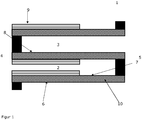
- FIG. 1 shows a particulate filter according to the invention, comprising a wall flow filter of length L (1) with channels E (2) and channels A (3) extending in parallel between a first end (4) and a second end (5) of the wall flow filter and are separated by porous walls (6) forming surfaces O E (7) and O A (8), respectively, and wherein the channels E (2) at the second end (5) and the channels A (3) at the first end (4 ) are closed.
- Coating Y (9) is located in the channels E (2) on the surfaces O E (7) and coating Z (10) in the porous walls (6).
- Alumina stabilized with lanthana was combined with a first oxygen storage component comprising 40% by weight of ceria, zirconia, lanthana and praseodymium oxide and a second oxygen storage component containing 24% by weight of ceria, zirconia, Lanthanum oxide and yttrium oxide, suspended in water. Both oxygen storage components were used in equal parts. The weight ratio of alumina and oxygen storage component was 30:70.
- the resulting suspension was then treated with continuous stirring with a palladium nitrate solution and a rhodium nitrate solution. The resulting coating suspension was used directly to coat a commercially available wall flow filter substrate, the coating being introduced into the porous filter wall over 100% of the substrate length.
- the total load of this filter was 100 g / l, the total noble metal loading was 0.44 g / l with a ratio of palladium to rhodium of 8: 3.
- the coated filter thus obtained was dried and then calcined. It will be referred to as VGPF1 below.
- Lanthanum oxide stabilized alumina was combined with a first oxygen storage component comprising 40% by weight of ceria, zirconia, lanthana and praseodymium oxide and a second oxygen storage component comprising 24% by weight of ceria, zirconia, lanthana and yttria in water suspended. Both oxygen storage components were used in equal parts. The weight ratio of alumina and oxygen storage component was 30:70.
- the resulting suspension was then treated with continuous stirring with a palladium nitrate solution and a rhodium nitrate solution.
- the resulting coating suspension was used directly to coat a commercially available wall flow filter substrate, the coating being introduced into the porous filter wall over 100% of the substrate length.
- the loading of this filter was 100 g / l, the noble metal loading 0.34 g / l with a ratio of palladium to rhodium of 16: 3.
- the coated filter thus obtained was dried and then calcined.
- Alumina stabilized with lanthana was suspended in water along with an oxygen storage component comprising 24% by weight of ceria, zirconia, lanthana and yttria. The weight ratio of alumina and oxygen storage component was 56:44.
- the resulting suspension was then treated with continuous stirring with a palladium nitrate solution and a rhodium nitrate solution.
- the resulting coating suspension was used directly for coating the wall flow filter substrate obtained under a), wherein the filter walls of the substrate were coated in the input channels to a length of 38% of the filter length.
- the loading of the inlet channel was 54 g / l, the noble metal loading 0.27 g / l with a ratio of palladium to rhodium of 2.6: 5.
- the coated filter thus obtained was dried and then calcined.
- the total loading of this filter was thus 121 g / l, the total precious metal loading 0.44 g / l with a ratio of palladium to rhodium of 8: 3. It is referred to below as GPF1.
- Table 1 below contains the temperatures T 50 at which in each case 50% of the components considered are reacted.
- Table 1 T 50 HC stöch T 50 CO stöch T 50 NOx stöch VGPF1 418 430 432 GPF1 377 384 387
- the particulate filter GPF1 according to the invention exhibits a marked improvement in the light-off behavior and in the dynamic CO / NOx conversion compared to VGPF1 in the aged state.
- Lanthanum oxide stabilized alumina was suspended in water along with a first oxygen storage component comprising 40% by weight of ceria, zirconia, lanthana and praseodymia and a second oxygen storage component comprising 24% by weight of ceria, zirconia, lanthana and yttria. Both oxygen storage components were used in equal parts. The weight ratio of alumina and oxygen storage component was 30:70.
- the suspension thus obtained was subsequently stirred with continuous stirring a palladium nitrate solution and a rhodium nitrate solution.
- the resulting coating suspension was used directly to coat a commercially available wall flow filter substrate, the coating being introduced into the porous filter wall over 100% of the substrate length.
- the total loading of this filter was 75 g / l, the noble metal loading was 0.71 g / l with a ratio of palladium to rhodium of 3: 1.
- the coated filter thus obtained was dried and then calcined.
- Lanthanum oxide stabilized alumina was suspended in water along with an oxygen storage component comprising 24% by weight of ceria, zirconia, lanthana and yttria. The weight ratio of alumina and oxygen storage component was 56:44. The resulting suspension was then treated with continuous stirring with a palladium nitrate solution and a rhodium nitrate solution. The resulting coating suspension was used directly for coating the wall flow filter substrate obtained under a), wherein the filter walls of the substrate were coated in the input channels to a length of 25% of the filter length. The loading of the inlet channel was 50 g / l, the noble metal loading 2.12 g / l with a ratio of palladium to rhodium of 5: 1. The coated filter thus obtained was dried and then calcined.
- Lanthanum oxide stabilized alumina was suspended in water along with an oxygen storage component comprising 24% by weight of ceria, zirconia, lanthana and yttria. The weight ratio of alumina and oxygen storage component was 56:44. The resulting suspension was then treated with continuous stirring with a palladium nitrate solution and a rhodium nitrate solution. The resulting coating suspension was used directly for coating the wall flow filter substrate obtained under b) was used, wherein the filter walls of the substrate was coated in the output channels to a length of 25% of the filter length. The loading of the exit channel was 50 g / l, the noble metal loading was 2.12 g / l with a ratio of palladium to rhodium of 5: 1.
- the coated filter thus obtained was dried and then calcined.
- the total loading of this filter was thus 100 g / l, the total noble metal loading 1.77 g / l with a ratio of palladium to rhodium of 4: 1. It will be referred to below as VGPF2.
- Lanthanum oxide stabilized alumina was suspended in water along with a first oxygen storage component comprising 40% by weight of ceria, zirconia, lanthana and praseodymia and a second oxygen storage component comprising 24% by weight of ceria, zirconia, lanthana and yttria. Both oxygen storage components were used in equal parts. The weight ratio of alumina and oxygen storage component was 30:70. The resulting suspension was then treated with continuous stirring with a palladium nitrate solution and a rhodium nitrate solution. The resulting coating suspension was used directly to coat a commercially available wall flow filter substrate, the coating being introduced into the porous filter wall over 100% of the substrate length. The loading of this filter was 50 g / l, the noble metal loading 0.71 g / l with a ratio of palladium to rhodium of 3: 1. The coated filter thus obtained was dried and then calcined.
- Alumina stabilized with lanthana was suspended in water along with an oxygen storage component comprising 24% by weight of ceria, zirconia, lanthana and yttria. The weight ratio of alumina and oxygen storage component was 56:44.
- the resulting suspension was then treated with continuous stirring with a palladium nitrate solution and a rhodium nitrate solution.
- the resulting coating suspension was used directly for coating the wall flow filter substrate obtained under a), wherein the filter walls of the substrate were coated in the input channels to a length of 60% of the filter length.
- the loading of the inlet channel was 83.3 g / l, the noble metal loading 1.77 g / l with a ratio of palladium to rhodium of 42: 8.
- the coated filter thus obtained was dried and then calcined.
- the total loading of this filter was thus 100 g / l, the total noble metal loading was 1.77 g / l with a ratio of palladium to rhodium of 4: 1. It is referred to below as GPF2.
- Table 1 below contains the temperatures Tso at which 50% of the components considered are reacted in each case.
- Table 1 T 50 HC stöch T 50 CO stöch T 50 NOx stöch VGPF2 356 360 365 GPF2 351 356 359
- the particulate filter according to the invention GPF2 shows compared to VGPF2 in the aged state, a significant improvement in the light-off and the dynamic CO / NOx conversion.
- Lanthanum oxide stabilized alumina was suspended in water along with a first oxygen storage component comprising 40% by weight of ceria, zirconia, lanthana and praseodymia and a second oxygen storage component comprising 24% by weight of ceria, zirconia, lanthana and yttria. Both oxygen storage components were used in equal parts. The weight ratio of alumina and oxygen storage component was 30:70. The resulting suspension was then treated with continuous stirring with a palladium nitrate solution and a rhodium nitrate solution. The resulting coating suspension was used directly to coat a commercially available wall flow filter substrate, the coating being introduced into the porous filter wall over 100% of the substrate length. The total loading of this filter was 100 g / l, the noble metal loading 2.60 g / l with a ratio of palladium to Rhodium of 60: 13.75. The coated filter thus obtained was dried and then calcined.
- Alumina stabilized with lanthana was suspended in water along with an oxygen storage component comprising 40% by weight of ceria, zirconia, lanthana and praseodymia. The weight ratio of alumina and oxygen storage component was 50:50.
- the resulting suspension was then treated with continuous stirring with a palladium nitrate solution and a rhodium nitrate solution.
- the resulting coating suspension was used directly for coating the wall flow filter substrate obtained under a), wherein the filter walls of the substrate were coated in the input channels to a length of 25% of the filter length.
- the loading of the inlet channel was 58 g / l, the noble metal loading 2.30 g / l with a ratio of palladium to rhodium of 10: 3.
- the coated filter thus obtained was dried and then calcined.
- Alumina stabilized with lanthana was suspended in water along with an oxygen storage component comprising 24% by weight of ceria, zirconia, lanthana and yttria. The weight ratio of alumina and oxygen storage component was 56:44.
- the resulting suspension was then treated with continuous stirring with a palladium nitrate solution and a rhodium nitrate solution.
- the resulting coating suspension was used directly for coating the wall flow filter substrate obtained under b), wherein the filter walls of the substrate were coated in the output channels to a length of 25% of the filter length.
- the loading of the outlet channel was 59 g / l, the noble metal loading 1.06 g / l with a ratio of palladium to rhodium of 1: 2.
- the thus obtained coated filter was dried and then calcined.
- the total loading of this filter was thus 130 g / l, the total precious metal loading 3.44 g / l with a ratio of palladium to rhodium of 10: 3. It is referred to below as VGPF3.
- Lanthanum oxide stabilized alumina was suspended in water along with a first oxygen storage component comprising 40% by weight of ceria, zirconia, lanthana and praseodymia and a second oxygen storage component comprising 24% by weight of ceria, zirconia, lanthana and yttria. Both oxygen storage components were used in equal parts. The weight ratio of alumina and oxygen storage component was 30:70. The resulting suspension was then treated with continuous stirring with a palladium nitrate solution and a rhodium nitrate solution. The resulting coating suspension was used directly to coat a commercially available wall flow filter substrate, the coating being introduced into the porous filter wall over 100% of the substrate length. The loading of this filter was 100 g / l, the noble metal loading 2.07 g / l with a ratio of palladium to rhodium of 45: 13.5. The coated filter thus obtained was dried and then calcined.
- Alumina stabilized with lanthana was suspended in water along with an oxygen storage component comprising 24% by weight of ceria, zirconia, lanthana and yttria. The weight ratio of alumina and oxygen storage component was 56:44.
- the resulting suspension was then treated with continuous stirring with a palladium nitrate solution and a rhodium nitrate solution.
- the resulting coating suspension was used directly for coating the wall flow filter substrate obtained under a), wherein the filter walls of the substrate were coated in the input channels to a length of 60% of the filter length.
- the Loading of the inlet channel was 80 g / l, the noble metal loading 2.30 g / l with a ratio of palladium to rhodium of 10: 3.
- the coated filter thus obtained was dried and then calcined.
- the total loading of this filter was thus 148 g / l, the total noble metal loading 3.44 g / l with a ratio of palladium to rhodium of 10: 3. It is referred to below as GPF3.
- Table 1 below contains the temperatures Tso at which 50% of the components considered are reacted in each case.
- Table 1 T 50 HC stöch T 50 CO stöch T 50 NOx stöch VGPF3 368 374 371 GPF3 341 345 340
- the particulate filter according to the invention GPF3 shows compared to VGPF3 in the aged state, a significant improvement in the light-off and the dynamic CO / NOx conversion.
Abstract
Description
- Die vorliegende Erfindung betrifft ein katalytisch aktives Partikelfilter, das sich insbesondere für die Entfernung von Partikeln, Kohlenmonoxid, Kohlenwasserstoffen und Stickoxiden aus dem Abgas von mit stöchiometrischem Luft/Kraftstoff-Gemisch betriebenen Verbrennungsmotoren eignet.
- Abgase von mit stöchiometrischem Luft/Kraftstoff-Gemisch betriebenen Verbrennungsmotoren, also Benzinmotoren, werden in herkömmlichen Verfahren mit Hilfe von Dreiwege-Katalysatoren gereinigt. Diese sind in der Lage, die drei wesentlichen gasförmigen Schadstoffe des Motors, nämlich Kohlenwasserstoffe, Kohlenmonoxid und Stickoxide, gleichzeitig zu unschädlichen Komponenten umzusetzen.
Neben diesen gasförmigen Schadstoffen enthält das Abgas von Benzinmotoren aber auch feinste Partikel (PM), die aus der unvollständigen Verbrennung des Kraftstoffs resultieren und im Wesentlichen aus Ruß bestehen. Im Unterschied zur Partikelemission von Dieselmotoren sind die Partikel im Abgas stöchiometrisch betriebener Verbrennungsmotoren sehr klein und weisen eine durchschnittliche Partikelgröße kleiner 1 µm auf. Typische Partikelgrößen liegen im Bereich 10 bis 200 nm. Des Weiteren ist die emittierte Partikelmenge sehr gering und bewegt sich im Bereich von 2 bis 4 mg/km.
Mit der europäischen Abgasnorm EU-6c ist eine Umstellung des Grenzwertes für solche Partikel vom Partikelmassengrenzwert auf einen kritischeren Partikelzahlgrenzwert von 6 x 10¹¹/km (im Worldwide harmonized Light vehicles Test Cycle - WLTP) verbunden. Damit entsteht Bedarf nach Abgasreinigungskonzepten für stöchiometrisch betriebene Verbrennungsmotoren, die effektiv arbeitende Einrichtungen zur Entfernung von Partikeln umfassen. - Im Bereich der Reinigung von Abgas von mager betriebenen Motoren, also insbesondere von Dieselmotoren, haben sich Wandflussfilter aus keramischen Materialien, wie z.B. Siliciumcarbid, Aluminiumtitanat und Cordierit bewährt. Diese sind aus einer Vielzahl von parallelen Kanälen aufgebaut, die durch poröse Wände gebildet werden. Die Kanäle sind wechselseitig an einem der beiden Enden des Filters verschlossen, so dass Kanäle A gebildet werden, die an der ersten Seite des Filters offen und auf der zweiten Seite des Filters verschlossen sind, sowie Kanäle B, die an der ersten Seite des Filters verschlossen und auf der zweiten Seite des Filters offen sind. Das beispielsweise in die Kanäle A einströmende Abgas kann den Filter nur über die Kanäle B wieder verlassen, und muss zu diesem Zweck durch die porösen Wände zwischen den Kanälen A und B durchfließen. Beim Durchtritt des Abgases durch die Wand werden die Partikel zurückgehalten und das Abgas gereinigt.
Die so zurückgehaltenen Partikel müssen nachfolgend abgebrannt bzw. oxidiert werden, um ein Verstopfen des Filters bzw. einen inakzeptablen Anstieg des Gegendrucks des Abgassystems zu verhindern. Zu diesem Zweck wird beispielsweise das Wandflussfilter mit katalytisch aktiven Beschichtungen versehen, die die Zündtemperatur von Ruß herabsetzen.
Es ist bereits bekannt, solche Beschichtungen auf die porösen Wände zwischen den Kanälen aufzubringen (sogenannte auf-Wand-Beschichtung) oder in die porösen Wände einzubringen (sogenannte in-Wand-Beschichtung). DieEP 1 657 410 A2 beschreibt auch bereits eine Kombination beider Beschichtungsarten, d.h. ein Teil des katalytisch aktiven Materials liegt in den porösen Wänden und ein anderer Teil auf den porösen Wänden vor. - Das Konzept, Partikel mittels Wandflussfiltern aus dem Abgas zu entfernen, ist bereits auf die Reinigung von Abgas von mit stöchiometrischem Luft/Kraftstoff-Gemisch betriebenen Verbrennungsmotoren übertragen worden, siehe zum Beispiel die
EP 2042226 A2 . Gemäß deren Lehre trägt ein Wandflussfilter zwei übereinander angeordnete Schichten, wobei eine in der porösen Wand und die andere auf der porösen Wand angeordnet sein kann.
Ein ähnliches Konzept verfolgt dieDE 102011050788 A1 . Dort enthalten die porösen Filterwände ein Katalysatormaterial eines Drei-Wege-Katalysators, während zusätzlich ein Katalysatormaterial eines Drei-Wege-Katalysators auf Teilbereiche der Filterwände aufgebracht ist. - Weitere Dokumente, die mit katalytisch aktiven Beschichtungen versehene Filtersubstrate beschreiben, sind
EP 3205388 A1 ,EP 3207977 A1 ,EP 3207978 A1 ,EP 3207987 A1 ,EP 3207989 A1 ,EP 3207990 A1 undEP 3162428 A1 . - Es besteht weiter Bedarf nach katalytisch aktiven Partikelfiltern, die die Funktionalitäten eines Partikelfilters und eines Dreiwegekatalysators vereinen und dabei die künftig geltenden Grenzwerte einzuhalten erlauben.
- Die vorliegende Erfindung betrifft ein Partikelfilter zur Entfernung von Partikeln, Kohlenmonoxid, Kohlenwasserstoffen und Stickoxiden aus dem Abgas von mit stöchiometrischem Luft/Kraftstoffgemisch betriebenen Verbrennungsmotoren, das ein Wandflussfilter der Länge L und zwei Beschichtungen Y und Z umfasst, wobei das Wandflussfilter Kanäle E und A umfasst, die sich parallel zwischen einem ersten und einem zweiten Ende des Wandflussfilters erstrecken und die durch poröse Wände getrennt sind, die Oberflächen OE bzw. OA bilden und wobei die Kanäle E am zweiten Ende und die Kanäle A am ersten Ende verschlossen sind, dadurch gekennzeichnet, dass sich Beschichtung Y in den Kanälen E auf den Oberflächen OE befindet und sich ausgehend vom ersten Ende des Wandflussfilters auf einer Länge von 51 bis 90 % der Länge L erstreckt und sich Beschichtung Z in den porösen Wänden befindet und sich ausgehend vom zweiten Ende des Wandflussfilters auf einer Länge von 60 bis 100 % der Länge L erstreckt.
- Die Beschichtungen Y und Z sind Dreiwege-katalytisch aktiv, insbesondere bei Betriebstemperaturen von 250 bis 1100 °C. Sie sind bevorzugt verschieden voneinander, beide enthalten aber üblicherweise ein oder mehrere Edelmetalle, die auf einem oder mehreren Trägermaterialien fixiert sind, sowie ein oder mehrere Sauerstoffspeicherkomponenten.
- Die Beschichtungen Y und Z können sich hinsichtlich der enthaltenen Komponenten unterscheiden. So können sie sich beispielsweise hinsichtlich der enthaltenen Edelmetalle oder hinsichtlich der enthaltenen Sauerstoffspeicherkomponenten unterscheiden. Sie können aber auch identische Bestandteile enthalten. Im letztgenannten Fall, können die Beschichtungen Y und Z die Bestandteile in gleichen oder verschiedenen Mengen enthalten.
- Als Edelmetalle kommen insbesondere Platin, Palladium und Rhodium in Frage, wobei Palladium, Rhodium oder Palladium und Rhodium bevorzugt und Palladium und Rhodium besonders bevorzugt sind.
Bezogen auf das erfindungsgemäße Partikelfilter ist der Anteil von Rhodium am gesamten Edelmetallgehalt insbesondere größer oder gleich 10 Gew.-%. - Die Edelmetalle werden üblicherweise in Mengen von 0,15 bis 5 g/l, bezogen auf das Volumen des Wandflussfilters eingesetzt.
- Als Trägermaterialien für die Edelmetalle kommen alle dem Fachmann für diesen Zweck geläufigen Materialien in Betracht. Solche Materialien sind insbesondere Metalloxide mit einer BET-Oberfläche von 30 bis 250 m2/g, bevorzugt von 100 bis 200 m2/g (bestimmt nach DIN 66132).
Besonders geeignete Trägermaterialien für die Edelmetalle sind ausgewählt aus der Reihe bestehend aus Aluminiumoxid, dotiertes Aluminiumoxid, Siliziumoxid, Titandioxid und Mischoxiden aus einem oder mehreren davon. Dotierte Aluminiumoxide sind beispielsweise Lanthanoxid-, Zirkoniumoxid- und/oder Titanoxid-dotierte Aluminiumoxide. Mit Vorteil wird Lanthan-stabilisiertes Aluminiumoxid eingesetzt, wobei Lanthan in Mengen von 1 bis 10 Gew.-%, bevorzugt 3 bis 6 Gew.-%, jeweils berechnet als La2O3 und bezogen auf das Gewicht des stabilisierten Aluminiumoxides, verwendet wird. - Als Sauerstoffspeicherkomponenten kommen insbesondere Cer/Zirkonium/ Seltenerdmetall-Mischoxide in Frage. Der Begriff "Cer/Zirkonium/ Seltenerdmetall-Mischoxid" im Sinne vorliegender Erfindung schließt physikalische Mischungen aus Ceroxid, Zirkoniumoxid und Seltenerdoxid aus. Vielmehr sind "Cer/Zirkonium/Seltenerdmetall-Mischoxide" durch eine weitgehend homogene, dreidimensionale Kristallstruktur gekennzeichnet, die idealerweise frei ist von Phasen aus reinem Ceroxid, Zirkoniumoxid bzw. Seltenerdoxid. Je nach Herstellungsverfahren können aber auch nicht vollständig homogene Produkte entstehen, die in der Regel ohne Nachteil verwendet werden können.
Im Übrigen umfasst der Begriff Seltenerdmetall bzw. Seltenerdmetalloxid im Sinne vorliegender Erfindung kein Cer bzw. kein Ceroxid. - Als Seltenerdmetalloxide in den Cer/Zirkonium/Seltenerdmetall-Mischoxiden kommen beispielsweise Lanthanoxid, Yttriumoxid, Praseodymoxid, Neodymoxid und/oder Samariumoxid in Betracht.
Bevorzugt sind Lanthanoxid, Yttriumoxid und/oder Praseodymoxid. Besonders bevorzugt sind Lanthanoxid und/oder Yttriumoxid und ganz besonders bevorzugt sind Lanthanoxid und Yttriumoxid, Yttriumoxid und Praseodymoxid, sowie Lanthanoxid und Praseodymoxid.
In Ausführungsformen der vorliegenden Erfindung sind die Sauerstoffspeicherkomponenten frei von Neodymoxid. - Erfindungsgemäß kann das Masseverhältnis von Ceroxid zu Zirkoniumoxid in den Cer/Zirkonium/Seltenerdmetall-Mischoxiden in weiten Grenzen variieren. Es beträgt beispielsweise 0,1 bis 1,5, bevorzugt 0,2 bis 1 oder 0,3 bis 0,5.
- In Ausführungsformen der vorliegenden Erfindung umfasst Beschichtung Y eine Sauerstoffspeicherkomponente mit einem Gehalt an Ceroxid von 20 bis 40 Gew.-%, bezogen auf das Gewicht der Sauerstoffspeicherkomponente.
- In Ausführungsformen der vorliegenden Erfindung umfasst Beschichtung Z eine Sauerstoffspeicherkomponente mit einem Gehalt an Ceroxid von 30 bis 60 Gew.-%, bezogen auf das Gewicht der Sauerstoffspeicherkomponente Lanthanoxid enthaltende Sauerstoffspeicherkomponenten weisen insbesondere ein Masseverhältnis von Lanthanoxid zu Ceroxid von 0,05 bis 0,5 auf.
- Üblicherweise enthalten die Beschichtungen Y und Z Sauerstoffspeicherkomponenten in Mengen von 15 bis 120 g/l, bezogen auf das Volumen des Wandflussfilters.
- Das Masseverhältnis von Trägermaterialien und Sauerstoffspeicherkomponenten in den Beschichtungen Y und Z beträgt üblicherweise 0,3 bis 1,5, beispielsweise 0,4 bis 1,3.
- In Ausführungsformen der vorliegenden Erfindung enthalten eine oder beide der Beschichtungen Y und Z eine Erdalkaliverbindung wie z.B. Strontiumoxid, Bariumoxid oder Bariumsulfat. Die Menge an Bariumsulfat je Beschichtung beträgt insbesondere 2 bis 20 g/l Volumen des Wandflussfilters.
Insbesondere enthält Beschichtung Z Strontiumoxid oder Bariumoxid. - In weiteren Ausführungsformen der vorliegenden Erfindung enthalten eine oder beide der Beschichtungen Y und Z Additive wie Seltenerdverbindungen wie z.B. Lanthanoxid und/oder Binder, wie z.B. Aluminiumverbindungen. Diese Additive werden in Mengen verwendet, die in weiten Grenzen variieren können und die der Fachmann im konkreten Fall mit einfachen Mitteln bestimmen kann.
- In Ausführungsformen der vorliegenden Erfindung sind die Beschichtungen Y und Z verschieden voneinander, wobei aber beide Lanthan-stabilisiertes Aluminiumoxid, sowie Rhodium, Palladium oder Palladium und Rhodium und eine Zirkoniumoxid, Ceroxid, Lanthanoxid, sowie Yttriumoxid und/oder Praeodymoxid umfassende Sauerstoffspeicherkomponente umfassen.
- In Beschichtung Y ist dabei der Yttriumoxid-Gehalt insbesondere 5 bis 15 Gew.-%, bezogen auf das Gewicht der Sauerstoffspeicherkomponente. Das Gewichtsverhältnis von Lanthanoxid zu Yttriumoxid beträgt insbesondere 0.1 bis 1.
- In Ausführungsformen der vorliegenden Erfindung ist der Gehalt von Yttriumoxid in der Sauerstoffspeicherkomponente der Beschichtung Z größer oder gleich dem Gehalt von Yttriumoxid in der Sauerstoffspeicherkomponente der Beschichtung Y, jeweils bezogen auf das Gewicht der jeweiligen Sauerstoffspeicherkomponente.
- Insbesondere Beschichtung Z kann eine zusätzliche Sauerstoffspeicherkomponente umfassen, die Zirkoniumoxid, Ceroxid, Praseodymoxid und Lanthanoxid enthält.
Dabei ist der Praseodymoxid-Gehalt insbesondere 2 bis 10 Gew.-%, bezogen auf das Gewicht der Sauerstoffspeicherkomponente. Das Gewichtsverhältnis von Lanthanoxid zu Praseodymoxid beträgt insbesondere 0.1 bis 1. - In Ausführungsformen der vorliegenden Erfindung ist in Beschichtung Z der Zirkoniumoxid-Gehalt des Yttriumoxid-haltigen Sauerstoffspeicherkomponente größer als der Zirkoniumoxid-Gehalt des Praseodymoxidhaltigen Sauerstoffspeicherkomponente, jeweils bezogen auf die jeweilige Sauerstoffspeicherkomponente.
- Die Beschichtungen Y und Z umfassen in Ausführungsformen jeweils Lanthan-stabilisiertes Aluminiumoxid in Mengen von 20 bis 70 Gew.-%, besonders bevorzugt 30 bis 60 Gew.-%, sowie Sauerstoffspeicherkomponente in Mengen von 30 bis 80 Gew.-%, besonders bevorzugt 40 bis 70 Gew.-%, jeweils bezogen auf das Gesamtgewicht der Beschichtung Y bzw. Z.
- In Ausführungsformen der vorliegenden Erfindung beträgt in Beschichtung Y das Gewichtsverhältnis von Aluminiumoxid zur Sauerstoffspeicherkomponente mindestens 0,7.
- In Ausführungsformen der vorliegenden Erfindung beträgt in Beschichtung Z das Gewichtsverhältnis von Aluminiumoxid zur Sauerstoffspeicherkomponente mindestens 0,3.
- In Ausführungsformen der vorliegenden Erfindung erstreckt sich die Beschichtung Y ausgehend vom ersten Ende des Wandflussfilters über 51 bis 90 %, insbesondere über 57 bis 65 % der Länge L des Wandflussfilters. Die Beladung des Wandflussfilters mit Beschichtung Y beträgt bevorzugt 33 bis 125 g/l, bezogen auf das Volumen des Wandflussfilters.
- In Ausführungsformen der vorliegenden Erfindung erstreckt sich die Beschichtung Z ausgehend vom zweiten Ende des Wandflussfilters über 51 bis 100 %, bevorzugt über 57 bis 100 %, besonders bevorzugt über 90 bis 100 % der Länge L des Wandflussfilters. Die Beladung des Wandflussfilters mit Beschichtung Z beträgt bevorzugt 33 bis 125 g/l, bezogen auf das Volumen des Wandflussfilters.
- Die Gesamtwashcoatbeladung des erfindungsgemäßen Partikelfilters beträgt insbesondere 40 bis 150 g/l, bezogen auf das Volumen des Wandflussfilters.
- In Ausführungsformen der vorliegenden Erfindung beträgt die Summe der Längen von Beschichtung Y und Beschichtung Z 110 bis 180 % der Länge L.
- In Ausführungsformen der vorliegenden Erfindung enthält weder Beschichtung Y, noch Beschichtung Z einen Zeolithen oder ein Molsieb.
- In einer Ausführungsform der vorliegenden Erfindung betrifft diese ein Partikelfilter, das ein Wandflussfilter der Länge L und zwei unterschiedliche Beschichtungen Y und Z umfasst, wobei das Wandflussfilter Kanäle E und A umfasst, die sich parallel zwischen einem ersten und einem zweiten Ende des Wandflussfilters erstrecken und die durch poröse Wände getrennt sind, die Oberflächen OE bzw. OA bilden und wobei die Kanäle E am zweiten Ende und die Kanäle A am ersten Ende verschlossen sind, wobei
Beschichtung Y sich in den Kanälen E auf den Oberflächen OE befindet und sich ausgehend vom ersten Ende des Wandflussfilters über 57 bis 65 % der Länge L erstreckt und Aluminiumoxid in einer Menge von 35 bis 60 Gew.-%, bezogen auf das Gesamtgewicht der Beschichtung Y, Palladium, Rhodium oder Palladium und Rhodium und eine Sauerstoffspeicherkomponente in einer Menge von 40 bis 50 Gew.-%, bezogen auf das Gesamtgewicht der Beschichtung Y enthält, wobei die Sauerstoffspeicherkomponente Zirkoniumoxid, Ceroxid, Lanthanoxid und Yttriumoxid oder Zirkoniumoxid, Ceroxid, Lanthanoxid und Praseodymoxid umfasst, und
Beschichtung Z sich in den porösen Wänden befindet und sich ausgehend vom zweiten Ende des Wandflussfilters über 60 bis 100 % der Länge L erstreckt und Aluminiumoxid in einer Menge von 25 bis 50 Gew.-%, bezogen auf das Gesamtgewicht der Beschichtung , Palladium, Rhodium oder Palladium und Rhodium und zwei Sauerstoffspeicherkomponenten in einer Gesamtmenge von 50 bis 80 Gew.-%, bezogen auf das Gesamtgewicht der Beschichtung Z enthält, wobei eine Sauerstoffspeicherkomponente Zirkoniumoxid, Ceroxid, Lanthanoxid und Yttriumoxid und die andere Zirkoniumoxid, Ceroxid, Lanthanoxid und Praseodymoxid enthält. - Wandflussfilter, die gemäß vorliegender Erfindung verwendet werden können, sind bekannt und am Markt erhältlich. Sie bestehen beispielsweise aus Silicium-Carbid, Aluminium-Titanat oder Cordierit, haben beispielsweise eine Zelligkeit von 200 bis 400 Zellen pro Inch und üblicherweise eine Wandstärke zwischen 6 und 12 Mil, bzw. 0,1524 und 0,305 Millimeter
Sie weisen in unbeschichtetem Zustand beispielsweise Porositäten von 50 bis 80, insbesondere 55 bis 75% auf. Ihre durchschnittliche Porengröße beträgt in unbeschichtetem Zustand beispielsweise 10 bis 25 Mikrometer. In der Regel sind die Poren des Wandflussfilters sogenannte offene Poren, das heißt sie haben eine Verbindung zur den Kanälen. Des Weiteren sind die Poren in der Regel untereinander verbunden. Dies ermöglicht einerseits die leichte Beschichtung der inneren Porenoberflächen und andererseits eine leichte Passage des Abgases durch die porösen Wände des Wandflussfilters. - Die Herstellung des erfindungsgemäßen Partikelfilters kann nach dem Fachmann geläufigen Methoden erfolgen, so etwa dadurch, dass eine Beschichtungssuspension, die üblicherweise Washcoat genannt wird, mittels eines der üblichen Tauchbeschichtungsverfahren bzw. Pump- und Saug-Beschichtungsverfahren auf das Wandflussfilter appliziert wird. Thermische Nachbehandlung bzw. Kalzination schließen sich üblicherweise an.
Die Beschichtungen Y und Z werden in getrennten und aufeinanderfolgenden Beschichtungsschritten erhalten. - Dem Fachmann ist bekannt, dass die durchschnittliche Porengröße des Wandflussfilters und die mittlere Teilchengröße der katalytisch aktiven Materialien aufeinander abgestimmt werden müssen, um eine auf-Wand-Beschichtung oder eine in-Wand-Beschichtung zu erzielen. In Fall der in-Wand-Beschichtung muss die mittlere Teilchengröße der katalytisch aktiven Materialien klein genug sein, um in die Poren des Wandflussfilters einzudringen. Dagegen muss im Fall der auf-Wand-Beschichtung die mittlere Teilchengröße der katalytisch aktiven Materialien groß genug sein, um nicht in die Poren des Wandflussfilters einzudringen.
- In Ausführungsformen der vorliegenden Erfindung werden die Beschichtungssuspensionen zur Herstellung der Beschichtungen Y bis zu einer Partikelgrößenverteilung von d50 = 4 bis 8 µm und d99 = 22 bis 16 µm gemahlen.
In Ausführungsformen der vorliegenden Erfindung werden die Beschichtungssuspensionen zur Herstellung der Beschichtungen Z bis zu einer Partikelgrößenverteilung von d50 = 1 bis 2 µm und d99 = 6 bis 7 µm gemahlen. - Das erfindungsgemäße Partikelfilter eignet sich hervorragend zur Entfernung von Partikeln, Kohlenmonoxid, Kohlenwasserstoffen und Stickoxiden aus dem Abgas von mit stöchiometrischem Luft/KraftstoffGemisch betriebenen Verbrennungsmotoren.
- Die vorliegende Erfindung betrifft somit auch ein Verfahren zur Entfernung von Partikeln, Kohlenmonoxid, Kohlenwasserstoffen und Stickoxiden aus dem Abgas von mit stöchiometrischem Luft/Kraftstoff-Gemisch betriebenen Verbrennungsmotoren, das dadurch gekennzeichnet ist, dass das Abgas über ein erfindungsgemäßes Partikelfilter geleitet wird.
- Dabei kann das Abgas so über ein erfindungsgemäßes Partikelfilter geleitet werden, dass es durch die Kanäle E in das Partikelfilter eintritt und es durch Kanäle A wieder verlässt.
Es ist aber auch möglich, dass das Abgas durch die Kanäle A in das Partikelfilter eintritt und es durch Kanäle E wieder verlässt. -
Figur 1 zeigt ein erfindungsgemäßes Partikelfilter, das ein Wandflussfilter der Länge L (1) mit Kanälen E (2) und Kanälen A (3) umfasst, die sich parallel zwischen einem ersten Ende (4) und einem zweiten Ende (5) des Wandflussfilters erstrecken und die durch poröse Wände (6) getrennt sind, die Oberflächen OE (7) bzw. OA (8) bilden und wobei die Kanäle E (2) am zweiten Ende (5) und die Kanäle A (3) am ersten Ende (4) verschlossen sind. Beschichtung Y (9) befindet sich in den Kanälen E (2) auf den Oberflächen OE (7) und Beschichtung Z (10) in den porösen Wänden (6). - Die Erfindung wird in den nachstehenden Beispielen näher erläutert.
- Mit Lanthanoxid stabilisiertes Aluminiumoxid wurde zusammen mit einer ersten Sauerstoffspeicherkomponente, die 40 Gew.-% Ceroxid, Zirkonoxid, Lanthanoxid und Praseodymoxid umfasste, und einer zweiten Sauerstoffspeicher-komponente, die 24 Gew.-% Ceroxid, Zirkonoxid, Lanthanoxid und Yttriumoxid umfasste, in Wasser suspendiert. Beide Sauerstoffspeicherkomponenten wurden zu gleichen Teilen eingesetzt. Das Gewichtsverhältnis von Aluminiumoxid und Sauerstoffspeicherkomponente betrug 30:70. Die so erhaltene Suspension wurde anschließend unter ständigem Rühren mit einer Palladiumnitrat-Lösung und einer Rhodiumnitrat-Lösung versetzt. Die resultierende Beschichtungssuspension wurde direkt zur Beschichtung eines handelsüblichen Wandflussfiltersubstrats eingesetzt, wobei die Beschichtung über 100% der Substratlänge in die poröse Filterwand eingebracht wurde. Die Gesamtbeladung dieses Filters betrug 100 g/l, die Gesamtedelmetallbeladung 0,44 g/l mit einem Verhältnis von Palladium zu Rhodium von 8 : 3. Der so erhaltene beschichtete Filter wurde getrocknet und anschließend kalziniert. Er wird nachstehend als VGPF1 bezeichnet.
- Mit Lanthanoxid stabilisiertes Aluminiumoxid wurde zusammen mit einer ersten Sauerstoffspeicherkomponente, die 40 Gew.-% Ceroxid, Zirkonoxid, Lanthanoxid und Praseodymoxid umfasste, und einer zweiten Sauerstoffspeicher-komponente, die 24 Gew.-% Ceroxid, Zirkonoxid, Lanthanoxid und Yttriumoxid umfasste, in Wasser suspendiert. Beide Sauerstoffspeicherkomponenten wurden zu gleichen Teilen eingesetzt. Das Gewichtsverhältnis von Aluminiumoxid und Sauerstoffspeicherkomponente betrug 30:70. Die so erhaltene Suspension wurde anschließend unter ständigem Rühren mit einer Palladiumnitrat-Lösung und einer Rhodiumnitrat-Lösung versetzt. Die resultierende Beschichtungssuspension wurde direkt zur Beschichtung eines handelsüblichen Wandflussfiltersubstrats eingesetzt, wobei die Beschichtung über 100% der Substratlänge in die poröse Filterwand eingebracht wurde. Die Beladung dieses Filters betrug 100 g/l, die Edelmetallbeladung 0,34 g/l mit einem Verhältnis von Palladium zu Rhodium von 16 : 3. Der so erhaltene beschichtete Filter wurde getrocknet und anschließend kalziniert.
- Mit Lanthanoxid stabilisiertes Aluminiumoxid wurde zusammen mit einer Sauerstoffspeicherkomponente, die 24 Gew-% Ceroxid, Zirkonoxid, Lanthanoxid und Yttriumoxid umfasste, in Wasser suspendiert. Das Gewichtsverhältnis von Aluminiumoxid und Sauerstoffspeicherkomponente betrug 56:44. Die so erhaltene Suspension wurde anschließend unter ständigem Rühren mit einer Palladiumnitrat-Lösung und einer Rhodiumnitrat-Lösung versetzt. Die resultierende Beschichtungssuspension wurde direkt zur Beschichtung des unter a) erhaltenen Wandflussfiltersubstrats eingesetzt, wobei auf die Filterwände des Substrats beschichtet wurde und zwar in den Eingangskanälen auf eine Länge von 38 % der Filterlänge. Die Beladung des Eingangskanals betrug 54 g/l, die Edelmetallbeladung 0,27 g/l mit einem Verhältnis von Palladium zu Rhodium von 2,6 : 5. Der so erhaltene beschichtete Filter wurde getrocknet und anschließend kalziniert. Die Gesamtbeladung dieses Filters betrug somit 121 g/l, die Gesamtedelmetallbeladung 0,44 g/l mit einem Verhältnis von Palladium zu Rhodium von 8 : 3. Er wird nachstehend als GPF1 bezeichnet.
- Die Partikelfilter VGPF1 und GPF1 wurden zusammen in einer Motorprüfstandsalterung gealtert. Diese besteht aus einer Schubabschaltungsalterung mit 950°C Abgastemperatur vor Katalysatoreingang (Maximale Betttemperatur 1030°C). Die Alterungszeit betrug 9,5 Stunden (siehe Motortechnische Zeitschrift, 1994, 55, 214-218).
Anschließend wurden die katalytisch aktiven Partikelfilter im gealterten Zustand an einem Motorprüfstand im sogenannten "Light-off Test" und im "lambda Sweeptest" getestet. Bei dem Light-off Test wird das Anspringverhalten bei stöchiometrischer Abgaszusammensetzung mit konstanter mittlerer Luftzahl λ bestimmt (λ =0,999 mit ±3,4% Amplitude). - Die nachfolgende Tabelle 1 enthält die Temperaturen T50, bei denen jeweils 50% der betrachteten Komponenten umgesetzt werden.
Tabelle 1 T50 HC stöch T50 CO stöch T50 NOx stöch VGPF1 418 430 432 GPF1 377 384 387 - Das dynamische Umsatzverhalten der Partikelfilter im lambda Sweeptest wurde in einem Bereich von λ = 0,99 - 1,01 bei einer konstanten Temperatur von 510°C bestimmt. Die Amplitude von λ betrug dabei ±6,8%. Tabelle 2 enthält den Umsatz am Schnittpunkt der CO- und der NOx-Umsatzkurven, sowie den zugehörigen HC-Umsatz der gealterten Partikelfilter.
Tabelle 2 CO/NOx Umsatz am Kreuzungspunkt HC Umsatz am λ des CO/NOx Kreuzungspunktes VGPF1 79% 94% GPF1 83% 95% - Der erfindungsgemäße Partikelfilter GPF1 zeigt gegenüber VGPF1 im gealterten Zustand eine deutliche Verbesserung beim Anspringverhalten und beim dynamischen CO/NOx-Umsatz.
- Mit Lanthanoxid stabilisiertes Aluminiumoxid wurde zusammen mit einer ersten Sauerstoffspeicherkomponente, die 40 Gew.-% Ceroxid, Zirkonoxid, Lanthanoxid und Praseodymoxid umfasste, und einer zweiten Sauerstoffspeicherkomponente, die 24 Gew.-% Ceroxid, Zirkonoxid, Lanthanoxid und Yttriumoxid umfasste, in Wasser suspendiert. Beide Sauerstoffspeicherkomponenten wurden zu gleichen Teilen eingesetzt. Das Gewichtsverhältnis von Aluminiumoxid und Sauerstoffspeicherkomponente betrug 30:70. Die so erhaltene Suspension wurde anschließend unter ständigem Rühren mit einer Palladiumnitrat-Lösung und einer Rhodiumnitrat-Lösung versetzt. Die resultierende Beschichtungssuspension wurde direkt zur Beschichtung eines handelsüblichen Wandflussfiltersubstrats eingesetzt, wobei die Beschichtung über 100% der Substratlänge in die poröse Filterwand eingebracht wurde. Die Gesamtbeladung dieses Filters betrug 75 g/l, die Edelmetallbeladung 0,71 g/l mit einem Verhältnis von Palladium zu Rhodium von 3 : 1. Der so erhaltene beschichtete Filter wurde getrocknet und anschließend kalziniert.
- Mit Lanthanoxid stabilisiertes Aluminiumoxid wurde zusammen mit einer Sauerstoffspeicherkomponente, die 24 Gew.-% Ceroxid, Zirkonoxid, Lanthanoxid und Yttriummoxid umfasste, in Wasser suspendiert. Das Gewichtsverhältnis von Aluminiumoxid und Sauerstoffspeicherkomponente betrug 56:44. Die so erhaltene Suspension wurde anschließend unter ständigem Rühren mit einer Palladiumnitrat-Lösung und einer Rhodiumnitrat-Lösung versetzt. Die resultierende Beschichtungssuspension wurde direkt zur Beschichtung des unter a) erhaltenen Wandflussfiltersubstrats eingesetzt, wobei auf die Filterwände des Substrats beschichtet wurde und zwar in den Eingangskanälen auf eine Länge von 25 % der Filterlänge. Die Beladung des Eingangskanals betrug 50 g/l, die Edelmetallbeladung 2,12 g/l mit einem Verhältnis von Palladium zu Rhodium von 5 : 1. Der so erhaltene beschichtete Filter wurde getrocknet und anschließend kalziniert.
- Mit Lanthanoxid stabilisiertes Aluminiumoxid wurde zusammen mit einer Sauerstoffspeicherkomponente, die 24 Gew.-% Ceroxid, Zirkonoxid, Lanthanoxid und Yttriummoxid umfasste, in Wasser suspendiert. Das Gewichtsverhältnis von Aluminiumoxid und Sauerstoffspeicherkomponente betrug 56:44. Die so erhaltene Suspension wurde anschließend unter ständigem Rühren mit einer Palladiumnitrat-Lösung und einer Rhodiumnitrat-Lösung versetzt. Die resultierende Beschichtungssuspension wurde direkt zur Beschichtung des unter b) erhaltenen Wandflussfiltersubstrats eingesetzt, wobei auf die Filterwände des Substrats beschichtet wurde und zwar in den Ausgangskanälen auf eine Länge von 25 % der Filterlänge. Die Beladung des Ausgangskanals betrug 50 g/l, die Edelmetallbeladung 2,12 g/l mit einem Verhältnis von Palladium zu Rhodium von 5 : 1. Der so erhaltene beschichtete Filter wurde getrocknet und anschließend kalziniert. Die Gesamtbeladung dieses Filters betrug somit 100 g/l, die Gesamtedelmetallbeladung 1,77 g/l mit einem Verhältnis von Palladium zu Rhodium von 4 : 1. Er wird nachstehend als VGPF2 bezeichnet.
- Mit Lanthanoxid stabilisiertes Aluminiumoxid wurde zusammen mit einer ersten Sauerstoffspeicherkomponente, die 40 Gew.-% Ceroxid, Zirkonoxid, Lanthanoxid und Praseodymoxid umfasste, und einer zweiten Sauerstoffspeicherkomponente, die 24 Gew.-% Ceroxid, Zirkonoxid, Lanthanoxid und Yttriumoxid umfasste, in Wasser suspendiert. Beide Sauerstoffspeicherkomponenten wurden zu gleichen Teilen eingesetzt. Das Gewichtsverhältnis von Aluminiumoxid und Sauerstoffspeicherkomponente betrug 30:70. Die so erhaltene Suspension wurde anschließend unter ständigem Rühren mit einer Palladiumnitrat-Lösung und einer Rhodiumnitrat-Lösung versetzt. Die resultierende Beschichtungssuspension wurde direkt zur Beschichtung eines handelsüblichen Wandflussfiltersubstrats eingesetzt, wobei die Beschichtung über 100% der Substratlänge in die poröse Filterwand eingebracht wurde. Die Beladung dieses Filters betrug 50 g/l, die Edelmetallbeladung 0,71 g/l mit einem Verhältnis von Palladium zu Rhodium von 3:1. Der so erhaltene beschichtete Filter wurde getrocknet und anschließend kalziniert.
- Mit Lanthanoxid stabilisiertes Aluminiumoxid wurde zusammen mit einer Sauerstoffspeicherkomponente, die 24 Gew-% Ceroxid, Zirkonoxid, Lanthanoxid und Yttriumoxid umfasste, in Wasser suspendiert. Das Gewichtsverhältnis von Aluminiumoxid und Sauerstoffspeicherkomponente betrug 56:44. Die so erhaltene Suspension wurde anschließend unter ständigem Rühren mit einer Palladiumnitrat-Lösung und einer Rhodiumnitrat-Lösung versetzt. Die resultierende Beschichtungssuspension wurde direkt zur Beschichtung des unter a) erhaltenen Wandflussfiltersubstrats eingesetzt, wobei auf die Filterwände des Substrats beschichtet wurde und zwar in den Eingangskanälen auf eine Länge von 60 % der Filterlänge. Die Beladung des Eingangskanals betrug 83,3 g/l, die Edelmetallbeladung 1,77 g/l mit einem Verhältnis von Palladium zu Rhodium von 42 : 8. Der so erhaltene beschichtete Filter wurde getrocknet und anschließend kalziniert. Die Gesamtbeladung dieses Filters betrug somit 100 g/l, die Gesamtedelmetallbeladung 1,77 g/l mit einem Verhältnis von Palladium zu Rhodium von 4 : 1. Er wird nachstehend als GPF2 bezeichnet.
- Die Partikelfilter VGPF2 und GPF2 wurden zusammen in einer Motorprüfstandsalterung gealtert. Diese besteht aus einer Schubabschaltungsalterung mit 950°C Abgastemperatur vor Katalysatoreingang (Maximale Betttemperatur 1030°C). Die Alterungszeit betrug 58 Stunden (siehe Motortechnische Zeitschrift, 1994, 55, 214-218).
Anschließend wurden die katalytisch aktiven Partikelfilter im gealterten Zustand an einem Motorprüfstand im sogenannten "Light-off Test" und im "lambda Sweeptest" getestet. Bei dem Light-off Test wird das Anspringverhalten bei stöchiometrischer Abgaszusammensetzung mit konstanter mittlerer Luftzahl λ bestimmt (λ =0,999 mit ±3,4% Amplitude). - Die nachfolgende Tabelle 1 enthält die Temperaturen Tso, bei denen jeweils 50% der betrachteten Komponenten umgesetzt werden.
Tabelle 1 T50 HC stöch T50 CO stöch T50 NOx stöch VGPF2 356 360 365 GPF2 351 356 359 - Das dynamische Umsatzverhalten der Partikelfilter im lambda Sweeptest wurde in einem Bereich von λ = 0,99 - 1,01 bei einer konstanten Temperatur von 510°C bestimmt. Die Amplitude von λ betrug dabei ±6,8%. Tabelle 2 enthält den Umsatz am Schnittpunkt der CO- und der NOx-Umsatzkurven, sowie den zugehörigen HC-Umsatz der gealterten Partikelfilter.
Tabelle 2 CO/NOx Umsatz am Kreuzungspunkt HC Umsatz am λ des CO/NOx Kreuzungspunktes VGPF2 79% 96% GPF2 86% 97% - Der erfindungsgemäße Partikelfilter GPF2 zeigt gegenüber VGPF2 im gealterten Zustand eine deutliche Verbesserung beim Anspringverhalten und beim dynamischen CO/NOx-Umsatz.
- Mit Lanthanoxid stabilisiertes Aluminiumoxid wurde zusammen mit einer ersten Sauerstoffspeicherkomponente, die 40 Gew.-% Ceroxid, Zirkonoxid, Lanthanoxid und Praseodymoxid umfasste, und einer zweiten Sauerstoffspeicherkomponente, die 24 Gew.-% Ceroxid, Zirkonoxid, Lanthanoxid und Yttriumoxid umfasste, in Wasser suspendiert. Beide Sauerstoffspeicherkomponenten wurden zu gleichen Teilen eingesetzt. Das Gewichtsverhältnis von Aluminiumoxid und Sauerstoffspeicherkomponente betrug 30:70. Die so erhaltene Suspension wurde anschließend unter ständigem Rühren mit einer Palladiumnitrat-Lösung und einer Rhodiumnitrat-Lösung versetzt. Die resultierende Beschichtungssuspension wurde direkt zur Beschichtung eines handelsüblichen Wandflussfiltersubstrats eingesetzt, wobei die Beschichtung über 100% der Substratlänge in die poröse Filterwand eingebracht wurde. Die Gesamtbeladung dieses Filters betrug 100 g/l, die Edelmetallbeladung 2,60 g/l mit einem Verhältnis von Palladium zu Rhodium von 60 : 13,75. Der so erhaltene beschichtete Filter wurde getrocknet und anschließend kalziniert.
- Mit Lanthanoxid stabilisiertes Aluminiumoxid wurde zusammen mit einer Sauerstoffspeicherkomponente, die 40 Gew.-% Ceroxid, Zirkonoxid, Lanthanoxid und Praseodymoxid umfasste, in Wasser suspendiert. Das Gewichtsverhältnis von Aluminiumoxid und Sauerstoffspeicherkomponente betrug 50:50. Die so erhaltene Suspension wurde anschließend unter ständigem Rühren mit einer Palladiumnitrat-Lösung und einer Rhodiumnitrat-Lösung versetzt. Die resultierende Beschichtungssuspension wurde direkt zur Beschichtung des unter a) erhaltenen Wandflussfiltersubstrats eingesetzt, wobei auf die Filterwände des Substrats beschichtet wurde und zwar in den Eingangskanälen auf eine Länge von 25 % der Filterlänge. Die Beladung des Eingangskanals betrug 58 g/l, die Edelmetallbeladung 2,30 g/l mit einem Verhältnis von Palladium zu Rhodium von 10 : 3. Der so erhaltene beschichtete Filter wurde getrocknet und anschließend kalziniert.
- Mit Lanthanoxid stabilisiertes Aluminiumoxid wurde zusammen mit einer Sauerstoffspeicherkomponente, die 24 Gew.-% Ceroxid, Zirkonoxid, Lanthanoxid und Yttriumoxid umfasste, in Wasser suspendiert. Das Gewichtsverhältnis von Aluminiumoxid und Sauerstoffspeicherkomponente betrug 56:44. Die so erhaltene Suspension wurde anschließend unter ständigem Rühren mit einer Palladiumnitrat-Lösung und einer Rhodiumnitrat-Lösung versetzt. Die resultierende Beschichtungssuspension wurde direkt zur Beschichtung des unter b) erhaltenen Wandflussfiltersubstrats eingesetzt, wobei auf die Filterwände des Substrats beschichtet wurde und zwar in den Ausgangskanälen auf eine Länge von 25 % der Filterlänge. Die Beladung des Auslasskanals betrug 59 g/l, die Edelmetallbeladung 1,06 g/l mit einem Verhältnis von Palladium zu Rhodium von 1 : 2. Der so erhaltene beschichtete Filter wurde getrocknet und anschließend kalziniert. Die Gesamtbeladung dieses Filters betrug somit 130 g/l, die Gesamtedelmetallbeladung 3,44 g/l mit einem Verhältnis von Palladium zu Rhodium von 10 : 3. Er wird nachstehend als VGPF3 bezeichnet.
- Mit Lanthanoxid stabilisiertes Aluminiumoxid wurde zusammen mit einer ersten Sauerstoffspeicherkomponente, die 40 Gew.-% Ceroxid, Zirkonoxid, Lanthanoxid und Praseodymoxid umfasste, und einer zweiten Sauerstoffspeicherkomponente, die 24 Gew.-% Ceroxid, Zirkonoxid, Lanthanoxid und Yttriumoxid umfasste, in Wasser suspendiert. Beide Sauerstoffspeicherkomponenten wurden zu gleichen Teilen eingesetzt. Das Gewichtsverhältnis von Aluminiumoxid und Sauerstoffspeicherkomponente betrug 30:70. Die so erhaltene Suspension wurde anschließend unter ständigem Rühren mit einer Palladiumnitrat-Lösung und einer Rhodiumnitrat-Lösung versetzt. Die resultierende Beschichtungssuspension wurde direkt zur Beschichtung eines handelsüblichen Wandflussfiltersubstrats eingesetzt, wobei die Beschichtung über 100% der Substratlänge in die poröse Filterwand eingebracht wurde. Die Beladung dieses Filters betrug 100 g/l, die Edelmetallbeladung 2,07 g/l mit einem Verhältnis von Palladium zu Rhodium von 45 : 13,5. Der so erhaltene beschichtete Filter wurde getrocknet und anschließend kalziniert.
- Mit Lanthanoxid stabilisiertes Aluminiumoxid wurde zusammen mit einer Sauerstoffspeicherkomponente, die 24 Gew-% Ceroxid, Zirkonoxid, Lanthanoxid und Yttriumoxid umfasste, in Wasser suspendiert. Das Gewichtsverhältnis von Aluminiumoxid und Sauerstoffspeicherkomponente betrug 56:44. Die so erhaltene Suspension wurde anschließend unter ständigem Rühren mit einer Palladiumnitrat-Lösung und einer Rhodiumnitrat-Lösung versetzt. Die resultierende Beschichtungssuspension wurde direkt zur Beschichtung des unter a) erhaltenen Wandflussfiltersubstrats eingesetzt, wobei auf die Filterwände des Substrats beschichtet wurde und zwar in den Eingangskanälen auf eine Länge von 60 % der Filterlänge. Die Beladung des Eingangskanals betrug 80 g/l, die Edelmetallbeladung 2,30 g/l mit einem Verhältnis von Palladium zu Rhodium von 10 : 3. Der so erhaltene beschichtete Filter wurde getrocknet und anschließend kalziniert. Die Gesamtbeladung dieses Filters betrug somit 148 g/l, die Gesamtedelmetallbeladung 3,44 g/l mit einem Verhältnis von Palladium zu Rhodium von 10 : 3. Er wird nachstehend als GPF3 bezeichnet.
- Die Partikelfilter VGPF3 und GPF3 wurden zusammen in einer Motorprüfstandsalterung gealtert. Diese besteht aus einer Schubabschaltungsalterung mit 950°C Abgastemperatur vor Katalysatoreingang (Maximale Betttemperatur 1030°C). Die Alterungszeit betrug 76 Stunden (siehe Motortechnische Zeitschrift, 1994, 55, 214-218).
Anschließend wurden die katalytisch aktiven Partikelfilter im gealterten Zustand an einem Motorprüfstand im sogenannten "Light-off Test" und im "lambda Sweeptest" getestet. Bei dem Light-off Test wird das Anspringverhalten bei stöchiometrischer Abgaszusammensetzung mit konstanter mittlerer Luftzahl λ bestimmt (λ =0,999 mit ±3,4% Amplitude). - Die nachfolgende Tabelle 1 enthält die Temperaturen Tso, bei denen jeweils 50% der betrachteten Komponenten umgesetzt werden.
Tabelle 1 T50 HC stöch T50 CO stöch T50 NOx stöch VGPF3 368 374 371 GPF3 341 345 340 - Das dynamische Umsatzverhalten der Partikelfilter im lambda Sweeptest wurde in einem Bereich von λ = 0,99 - 1,01 bei einer konstanten Temperatur von 510°C bestimmt. Die Amplitude von λ betrug dabei ±6,8%. Tabelle 2 enthält den Umsatz am Schnittpunkt der CO- und der NOx-Umsatzkurven, sowie den zugehörigen HC-Umsatz der gealterten Partikelfilter.
Tabelle 2 CO/NOx Umsatz am Kreuzungspunkt HC Umsatz am λ des CO/NOx Kreuzungspunktes VGPF3 83% 97% GPF3 90% 98% - Der erfindungsgemäße Partikelfilter GPF3 zeigt gegenüber VGPF3 im gealterten Zustand eine deutliche Verbesserung beim Anspringverhalten und beim dynamischen CO/NOx-Umsatz.
Claims (14)
- Partikelfilter zur Entfernung von Partikeln, Kohlenmonoxid, Kohlenwasserstoffen und Stickoxiden aus dem Abgas von mit stöchiometrischem Luft/Kraftstoffgemisch betriebenen Verbrennungsmotoren, das ein Wandflussfilter der Länge L und zwei unterschiedliche Beschichtungen Y und Z umfasst, wobei das Wandflussfilter Kanäle E und A umfasst, die sich parallel zwischen einem ersten und einem zweiten Ende des Wandflussfilters erstrecken und die durch poröse Wände getrennt sind, die Oberflächen OE bzw. OA bilden und wobei die Kanäle E am zweiten Ende und die Kanäle A am ersten Ende verschlossen sind, dadurch gekennzeichnet, dass sich Beschichtung Y in den Kanälen E auf den Oberflächen OE befindet und sich ausgehend vom ersten Ende des Wandflussfilters auf einer Länge von 51 bis 90 % der Länge L erstreckt und sich Beschichtung Z in den porösen Wänden befindet und sich ausgehend vom zweiten Ende des Wandflussfilters auf einer Länge von 60 bis 100 % der Länge L erstreckt.
- Partikelfilter gemäß Anspruch 1, dadurch gekennzeichnet, dass sich die Beschichtung Y ausgehend vom ersten Ende des Wandflussfilters auf 51 bis 80 % der Länge L des Wandflussfilters erstreckt.
- Partikelfilter gemäß Anspruch 2, dadurch gekennzeichnet, dass sich die Beschichtung Y ausgehend vom ersten Ende des Wandflussfilters auf 57 bis 65 % der Länge L des Wandflussfilters erstreckt.
- Partikelfilter gemäß Anspruch 1 und/oder 2 und oder 3, dadurch gekennzeichnet, dass die Beschichtungen Y und Z jeweils ein oder mehrere Edelmetalle, die auf einem oder mehreren Trägermaterialien fixiert sind, sowie ein oder mehrere Sauerstoffspeicherkomponenten enthalten.
- Partikelfilter gemäß Anspruch 4, dadurch gekennzeichnet, dass die Beschichtungen Y und Z jeweils die Edelmetalle Platin, Palladium und/oder Rhodium enthalten.
- Partikelfilter gemäß Anspruch 4 und/oder 5, dadurch gekennzeichnet, dass die Beschichtungen Y und Z jeweils die Edelmetalle Palladium, Rhodium oder Palladium und Rhodium enthalten.
- Partikelfilter gemäß einem oder mehreren der Ansprüche 3 bis 5, dadurch gekennzeichnet, dass die Trägermaterialien für die Edelmetalle Metalloxide mit einer BET-Oberfläche von 30 bis 250 m2/g (bestimmt nach DIN 66132) sind.
- Partikelfilter gemäß einem oder mehreren der Ansprüche 4 bis 6, dadurch gekennzeichnet, dass die Trägermaterialien für die Edelmetalle ausgewählt sind aus der Reihe bestehend aus Aluminiumoxid, dotiertes Aluminiumoxid, Siliziumoxid, Titandioxid und Mischoxiden aus einem oder mehreren davon.
- Partikelfilter gemäß einem oder mehreren der Ansprüche 4 bis 8, dadurch gekennzeichnet, dass die Beschichtungen Y und Z als Sauerstoffspeicherkomponente ein Cer/Zirkonium/Seltenerdmetall-Mischoxide enthalten.
- Partikelfilter gemäß Anspruch 9, dadurch gekennzeichnet, dass die Cer/Zirkonium/Seltenerdmetall-Mischoxide als Seltenerdmetalloxid Lanthanoxid, Yttriumoxid, Praseodymoxid, Neodymoxid und/oder Samariumoxid enthalten
- Partikelfilter gemäß Anspruch 9 und/oder 10, dadurch gekennzeichnet, dass die Cer/Zirkonium/Seltenerdmetall-Mischoxide als Seltenerdmetalloxid Lanthanoxid und Yttriumoxid, Yttriumoxid und Praseodymoxid oder Lanthanoxid und Praseodymoxid enthalten.
- Partikelfilter gemäß einem oder mehreren der Ansprüche 4 bis 11, dadurch gekennzeichnet, dass die Beschichtungen Y und Z beide Lanthan-stabilisiertes Aluminiumoxid, Palladium, Rhodium oder Palladium und Rhodium und eine Zirkoniumoxid, Ceroxid, Yttriumoxid und Lanthanoxid und/oder eine Zirkoniumoxid, Ceroxid, Praseodymoxid und Lanthanoxid umfassende Sauerstoffspeicherkomponente umfassen.
- Partikelfilter gemäß einem oder mehreren der Ansprüche 1 bis 12, das ein Wandflussfilter der Länge L und zwei unterschiedliche Beschichtungen Y und Z umfasst, wobei das Wandflussfilter Kanäle E und A umfasst, die sich parallel zwischen einem ersten und einem zweiten Ende des Wandflussfilters erstrecken und die durch poröse Wände getrennt sind, die Oberflächen OE bzw. OA bilden und wobei die Kanäle E am zweiten Ende und die Kanäle A am ersten Ende verschlossen sind, dadurch gekennzeichnet, dass Beschichtung Y sich in den Kanälen E auf den Oberflächen OE befindet und sich ausgehend vom ersten Ende des Wandflussfilters über 57 bis 65 % der Länge L erstreckt und Aluminiumoxid in einer Menge von 35 bis 60 Gew.-%, bezogen auf das Gesamtgewicht der Beschichtung Y, Palladium, Rhodium oder Palladium und Rhodium und eine Sauerstoffspeicherkomponente in einer Menge von 40 bis 50 Gew.-%, bezogen auf das Gesamtgewicht der Beschichtung Y enthält, wobei die Sauerstoffspeicherkomponente Zirkoniumoxid, Ceroxid, Lanthanoxid und Yttriumoxid oder Zirkoniumoxid, Ceroxid, Lanthanoxid und Praseodymoxid umfasst, und
Beschichtung Z sich in den porösen Wänden befindet und sich ausgehend vom zweiten Ende des Wandflussfilters über 60 bis 100 % der Länge L erstreckt und Aluminiumoxid in einer Menge von 25 bis 50 Gew.-%, bezogen auf das Gesamtgewicht der Beschichtung , Palladium, Rhodium oder Palladium und Rhodium und zwei Sauerstoffspeicherkomponenten in einer Gesamtmenge von 50 bis 80 Gew.-%, bezogen auf das Gesamtgewicht der Beschichtung Z enthält, wobei eine Sauerstoffspeicherkomponente Zirkoniumoxid, Ceroxid, Lanthanoxid und Yttriumoxid und die andere Zirkoniumoxid, Ceroxid, Lanthanoxid und Praseodymoxid enthält. - Verfahren zur Entfernung von Partikeln, Kohlenmonoxid, Kohlenwasserstoffen und Stickoxiden aus dem Abgas von mit stöchiometrischem Luft/Kraftstoff-Gemisch betriebenen Verbrennungsmotoren, dadurch gekennzeichnet, dass das Abgas über ein Partikelfilter gemäß einem oder mehreren der Ansprüche 1 bis 13 geleitet wird.
Priority Applications (18)
| Application Number | Priority Date | Filing Date | Title |
|---|---|---|---|
| EP17208615.9A EP3501648B1 (de) | 2017-12-19 | 2017-12-19 | Katalytisch aktives partikelfilter |
| PCT/EP2018/084902 WO2019121375A1 (de) | 2017-12-19 | 2018-12-14 | Katalytisch aktives partikelfilter |
| CN201880082178.1A CN111511469B (zh) | 2017-12-19 | 2018-12-14 | 催化活性微粒过滤器 |
| CN202211568967.0A CN115990408A (zh) | 2017-12-19 | 2018-12-14 | 催化活性微粒过滤器 |
| US16/954,323 US11628400B2 (en) | 2017-12-19 | 2018-12-14 | Catalytically active particulate filter |
| EP18816073.3A EP3727653B1 (de) | 2017-12-19 | 2018-12-14 | Katalytisch aktives partikelfilter |
| US16/954,305 US11179676B2 (en) | 2017-12-19 | 2018-12-14 | Catalytically active particulate filter |
| PCT/EP2018/084898 WO2019121372A1 (de) | 2017-12-19 | 2018-12-14 | Katalytisch aktives partikelfilter |
| CN201880082071.7A CN111491715B (zh) | 2017-12-19 | 2018-12-14 | 催化活性微粒过滤器 |
| US16/954,628 US11185820B2 (en) | 2017-12-19 | 2018-12-19 | Multi-layer three-way catalytic converter |
| US16/954,637 US11291952B2 (en) | 2017-12-19 | 2018-12-19 | Single-layer 3-way catalytic converter |
| CN201880081997.4A CN111511457A (zh) | 2017-12-19 | 2018-12-19 | 多层三元催化转化器 |
| EP18826338.8A EP3727654A1 (de) | 2017-12-19 | 2018-12-19 | Mehrschichtiger dreiwegekatalysator |
| CN201880081450.4A CN111491714B (zh) | 2017-12-19 | 2018-12-19 | 单层3元催化转化器 |
| PCT/EP2018/085962 WO2019121995A1 (de) | 2017-12-19 | 2018-12-19 | Einschichtiger dreiwegekatalysator |
| PCT/EP2018/085961 WO2019121994A1 (de) | 2017-12-19 | 2018-12-19 | Mehrschichtiger dreiwegekatalysator |
| EP18826640.7A EP3727655A1 (de) | 2017-12-19 | 2018-12-19 | Einschichtiger dreiwegekatalysator |
| US18/177,490 US20230285899A1 (en) | 2017-12-19 | 2023-03-02 | Catalytically active particulate filter |
Applications Claiming Priority (1)
| Application Number | Priority Date | Filing Date | Title |
|---|---|---|---|
| EP17208615.9A EP3501648B1 (de) | 2017-12-19 | 2017-12-19 | Katalytisch aktives partikelfilter |
Publications (2)
| Publication Number | Publication Date |
|---|---|
| EP3501648A1 true EP3501648A1 (de) | 2019-06-26 |
| EP3501648B1 EP3501648B1 (de) | 2023-10-04 |
Family
ID=60923283
Family Applications (4)
| Application Number | Title | Priority Date | Filing Date |
|---|---|---|---|
| EP17208615.9A Active EP3501648B1 (de) | 2017-12-19 | 2017-12-19 | Katalytisch aktives partikelfilter |
| EP18816073.3A Active EP3727653B1 (de) | 2017-12-19 | 2018-12-14 | Katalytisch aktives partikelfilter |
| EP18826640.7A Pending EP3727655A1 (de) | 2017-12-19 | 2018-12-19 | Einschichtiger dreiwegekatalysator |
| EP18826338.8A Pending EP3727654A1 (de) | 2017-12-19 | 2018-12-19 | Mehrschichtiger dreiwegekatalysator |
Family Applications After (3)
| Application Number | Title | Priority Date | Filing Date |
|---|---|---|---|
| EP18816073.3A Active EP3727653B1 (de) | 2017-12-19 | 2018-12-14 | Katalytisch aktives partikelfilter |
| EP18826640.7A Pending EP3727655A1 (de) | 2017-12-19 | 2018-12-19 | Einschichtiger dreiwegekatalysator |
| EP18826338.8A Pending EP3727654A1 (de) | 2017-12-19 | 2018-12-19 | Mehrschichtiger dreiwegekatalysator |
Country Status (4)
| Country | Link |
|---|---|
| US (5) | US11628400B2 (de) |
| EP (4) | EP3501648B1 (de) |
| CN (5) | CN111491715B (de) |
| WO (4) | WO2019121372A1 (de) |
Cited By (1)
| Publication number | Priority date | Publication date | Assignee | Title |
|---|---|---|---|---|
| WO2024028197A1 (de) | 2022-08-05 | 2024-02-08 | Umicore Ag & Co. Kg | Katalytisch aktiver partikelfilter mit hoher filtrationseffizienz und oxidationsfunktion |
Families Citing this family (10)
| Publication number | Priority date | Publication date | Assignee | Title |
|---|---|---|---|---|
| EP3501646A1 (de) | 2017-12-19 | 2019-06-26 | Umicore Ag & Co. Kg | Katalytisch aktives partikelfilter |
| EP3505246B1 (de) | 2017-12-19 | 2019-10-23 | Umicore Ag & Co. Kg | Katalytisch aktives partikelfilter |
| EP3501648B1 (de) | 2017-12-19 | 2023-10-04 | Umicore Ag & Co. Kg | Katalytisch aktives partikelfilter |
| US20210381921A1 (en) * | 2020-06-03 | 2021-12-09 | Becton, Dickinson And Company | Capillary-based pressure threshold sensor for liquids and methods and apparatuses using same |
| DE102021118801A1 (de) | 2021-07-21 | 2023-01-26 | Umicore Ag & Co. Kg | Abgasreinigungssystem zur Reinigung von Abgasen von Benzinmotoren |
| DE102021118802A1 (de) | 2021-07-21 | 2023-01-26 | Umicore Ag & Co. Kg | Abgasreinigungssystem zur Reinigung von Abgasen von Benzinmotoren |
| DE102021118803A1 (de) | 2021-07-21 | 2023-01-26 | Umicore Ag & Co. Kg | Abgasreinigungssystem zur Reinigung von Abgasen von Benzinmotoren |
| EP4159310A1 (de) | 2021-10-01 | 2023-04-05 | UMICORE AG & Co. KG | Katalytische beschichtung |
| WO2023198569A1 (de) | 2022-04-11 | 2023-10-19 | Umicore Ag & Co. Kg | Ammoniaksperrkatalysator für stöchiometrische verbrennungsmotoren |
| DE102023101768A1 (de) | 2022-04-11 | 2023-10-12 | Umicore Ag & Co. Kg | Abgassystem für überwiegend stöchiometrisch betriebene Verbrennungsmotoren aufweisend einen Katalysator zur Verminderung der Ammoniakemissionen |
Citations (15)
| Publication number | Priority date | Publication date | Assignee | Title |
|---|---|---|---|---|
| EP1657410A2 (de) | 2004-11-11 | 2006-05-17 | Cataler Corporation | Filterkatalysator |
| EP2042226A2 (de) | 2007-09-27 | 2009-04-01 | Umicore AG & Co. KG | Entfernung von Partikeln aus dem Abgas von mit überwiegend stöchiometrischen Luft/Kraftstoff-Gemisch betriebenen Verbrennungsmotoren |
| EP2042225A1 (de) * | 2007-09-28 | 2009-04-01 | Umicore AG & Co. KG | Entfernung von Partikeln aus dem Abgas von mit überwiegend stöchiometrischem Luft/Kraftstoff-Gemisch betriebenen Verbrennungsmotoren |
| EP2322773A1 (de) * | 2009-10-28 | 2011-05-18 | Umicore AG & Co. KG | Verfahren zue Reinigung von Verbrennungsmotorenabgasen |
| DE102011050788A1 (de) | 2011-06-01 | 2012-12-06 | Ford Global Technologies, Llc. | Abgasnachbehandlungsvorrichtung und -verfahren für einen Ottomotor |
| US20140140899A1 (en) * | 2011-07-13 | 2014-05-22 | Haldor Topsøe A/S | Catalysed particulate filter and method for the preparation of a catalysed particulate filter |
| WO2014178633A1 (ko) * | 2013-05-02 | 2014-11-06 | 희성촉매 주식회사 | 가솔린직접분사엔진 매연여과용 촉매식 필터 |
| EP3162428A1 (de) | 2015-10-30 | 2017-05-03 | Cataler Corporation | Abgasreinigungsvorrichtung |
| EP3205388A1 (de) | 2014-10-09 | 2017-08-16 | Cataler Corporation | Abgasreinigungsvorrichtung |
| EP3207990A1 (de) | 2014-10-16 | 2017-08-23 | Cataler Corporation | Abgasreinigungskatalysator |
| EP3207989A1 (de) | 2014-10-16 | 2017-08-23 | Cataler Corporation | Abgasreinigungskatalysator |
| EP3207987A1 (de) | 2014-10-16 | 2017-08-23 | Cataler Corporation | Abgasreinigungskatalysator |
| EP3207978A1 (de) | 2014-10-17 | 2017-08-23 | Cataler Corporation | Abgasreinigungsvorrichtung |
| EP3207977A1 (de) | 2014-10-17 | 2017-08-23 | Cataler Corporation | Abgasreinigungsvorrichtung |
| WO2017209083A1 (en) * | 2016-06-02 | 2017-12-07 | Cataler Corporation | Exhaust gas purification filter |
Family Cites Families (84)
| Publication number | Priority date | Publication date | Assignee | Title |
|---|---|---|---|---|
| US4335023A (en) | 1980-01-24 | 1982-06-15 | Engelhard Corporation | Monolithic catalyst member and support therefor |
| JP3406322B2 (ja) | 1991-09-10 | 2003-05-12 | ソニー株式会社 | Ecr型プラズマ処理装置 |
| US5471431A (en) | 1993-04-22 | 1995-11-28 | Sgs-Thomson Microelectronics, Inc. | Structure to recover a portion of a partially functional embedded memory |
| JPH10501737A (ja) | 1994-06-17 | 1998-02-17 | エンゲルハード・コーポレーシヨン | 層状触媒複合体 |
| FR2748740B1 (fr) | 1996-05-15 | 1998-08-21 | Rhone Poulenc Chimie | Composition a base d'oxyde de cerium et d'oxyde de zirconium a haute surface specifique et a capacite elevee de stockage d'oxygene, procede de preparation et utilisation en catalyse |
| US6348430B1 (en) | 1997-06-20 | 2002-02-19 | Degussa Ag | Exhaust gas treatment catalyst for internal combustion engines with two catalytically active layers on a carrier structure |
| DE19726322A1 (de) | 1997-06-20 | 1998-12-24 | Degussa | Abgasreinigungskatalysator für Verbrennungsmotoren mit zwei katalytisch aktiven Schichten auf einem Tragkörper |
| EP1046423B8 (de) | 1999-04-23 | 2007-11-21 | Umicore AG & Co. KG | Mehrschichtiger Edelmetall-enthaltender Abgaskatalysator und seine Herstellung |
| US6294140B1 (en) | 1999-04-23 | 2001-09-25 | Degussa Ag | Layered noble metal-containing exhaust gas catalyst and its preparation |
| US20040065078A1 (en) * | 2000-09-29 | 2004-04-08 | Adolf Schafer-Sindlinger | Catalytic soot filter and use thereof in treatment of lean exhaust gases |
| US6663588B2 (en) | 2000-11-29 | 2003-12-16 | C.R. Bard, Inc. | Active counterforce handle for use in bidirectional deflectable tip instruments |
| CN1234453C (zh) | 2002-08-07 | 2006-01-04 | 昆明贵研催化剂有限责任公司 | 贵金属-稀土废气净化催化剂 |
| US7875250B2 (en) | 2003-12-11 | 2011-01-25 | Umicore Ag & Co. Kg | Exhaust treatment device, and methods of making the same |
| DE102004040549B4 (de) | 2004-08-21 | 2017-03-23 | Umicore Ag & Co. Kg | Katalytisch beschichtetes Partikelfilter und seine Verwendung |
| US7722829B2 (en) * | 2004-09-14 | 2010-05-25 | Basf Catalysts Llc | Pressure-balanced, catalyzed soot filter |
| JP4768260B2 (ja) | 2004-12-27 | 2011-09-07 | 株式会社キャタラー | 排ガス浄化用触媒 |
| DE102005005663A1 (de) | 2005-02-08 | 2006-08-17 | Daimlerchrysler Ag | Abgasnachbehandlungseinrichtung mit Partikelfilter |
| JP4648089B2 (ja) | 2005-05-27 | 2011-03-09 | 株式会社キャタラー | 排ガス浄化用触媒 |
| JP4687389B2 (ja) | 2005-10-26 | 2011-05-25 | マツダ株式会社 | 排気ガス浄化触媒 |
| US8119075B2 (en) | 2005-11-10 | 2012-02-21 | Basf Corporation | Diesel particulate filters having ultra-thin catalyzed oxidation coatings |
| KR101076945B1 (ko) | 2006-02-17 | 2011-10-26 | 로디아 오퍼레이션스 | 지르코늄, 세륨, 이트륨, 란타늄의 산화물 및 또 다른 희토류의 산화물을 기재로 하는 조성물, 그의 제조 방법 및 촉매 용도 |
| RU2009102771A (ru) * | 2006-06-29 | 2010-08-10 | Умикоре Аг Унд Ко. Кг (De) | Трехкомпонентный каталитический нейтрализатор отработанных газов |
| CN100427205C (zh) | 2006-09-06 | 2008-10-22 | 天津化工研究设计院 | 一种降低冷起动尾气排放净化催化剂的制备方法 |
| EP1911506B1 (de) * | 2006-10-06 | 2009-08-19 | Umicore AG & Co. KG | Stickoxidspeicherkatalysator mit abgesenkter Entschwefelungstemperatur |
| JP5100244B2 (ja) | 2006-10-12 | 2012-12-19 | 第一稀元素化学工業株式会社 | ジルコニア・セリア・イットリア系複合酸化物及びその製造方法 |
| ATE482766T1 (de) | 2007-03-19 | 2010-10-15 | Umicore Ag & Co Kg | Doppelschichtiger dreiweg-katalysator |
| ATE477849T1 (de) | 2007-03-19 | 2010-09-15 | Umicore Ag & Co Kg | Palladium-rhodium einfachschicht katalysator |
| US8007750B2 (en) | 2007-07-19 | 2011-08-30 | Basf Corporation | Multilayered catalyst compositions |
| EP2044999B1 (de) | 2007-10-01 | 2012-02-01 | Mazda Motor Corporation | Partikelfilter |
| US8173087B2 (en) | 2008-02-05 | 2012-05-08 | Basf Corporation | Gasoline engine emissions treatment systems having particulate traps |
| DE102008010388B4 (de) * | 2008-02-21 | 2015-04-16 | Umicore Ag & Co. Kg | Verfahren zur Beschichtung eines Dieselpartikelfilters und damit hergestelltes Dieselpartikelfilter |
| GB0812544D0 (en) | 2008-07-09 | 2008-08-13 | Johnson Matthey Plc | Exhaust system for a lean burn IC engine |
| KR101028548B1 (ko) | 2008-09-05 | 2011-04-11 | 기아자동차주식회사 | 배기가스 정화장치 |
| EP2974779A1 (de) | 2008-11-04 | 2016-01-20 | Umicore AG & Co. KG | Dieselpartikelfilter mit verbesserten staudruckeigenschaften |
| GB0903262D0 (en) | 2009-02-26 | 2009-04-08 | Johnson Matthey Plc | Filter |
| US8758695B2 (en) | 2009-08-05 | 2014-06-24 | Basf Se | Treatment system for gasoline engine exhaust gas |
| US8815189B2 (en) | 2010-04-19 | 2014-08-26 | Basf Corporation | Gasoline engine emissions treatment systems having particulate filters |
| FR2959735B1 (fr) | 2010-05-06 | 2012-06-22 | Rhodia Operations | Composition a base d'oxydes de zirconium, de cerium d'au moins une autre terre rare, a porosite specifique, procede de preparation et utilisation en catalyse. |
| US8722000B2 (en) * | 2011-03-29 | 2014-05-13 | Basf Corporation | Multi-component filters for emissions control |
| JP5724856B2 (ja) | 2011-12-02 | 2015-05-27 | トヨタ自動車株式会社 | 排ガス浄化用触媒 |
| EP2623183B1 (de) * | 2012-02-03 | 2015-08-26 | Umicore AG & Co. KG | Katalytisch aktives partikelfilter und dessen verwendung |
| WO2013145266A1 (ja) | 2012-03-30 | 2013-10-03 | トヨタ自動車株式会社 | パティキュレートフィルタ |
| EP2650042B2 (de) | 2012-04-13 | 2020-09-02 | Umicore AG & Co. KG | Schadstoffminderungssystem für Benzinfahrzeuge |
| JP5982987B2 (ja) | 2012-04-23 | 2016-08-31 | マツダ株式会社 | 排気ガス浄化用触媒材を含有する排気ガス浄化用触媒 |
| GB2513364B (en) | 2013-04-24 | 2019-06-19 | Johnson Matthey Plc | Positive ignition engine and exhaust system comprising catalysed zone-coated filter substrate |
| GB201207313D0 (en) | 2012-04-24 | 2012-06-13 | Johnson Matthey Plc | Filter substrate comprising three-way catalyst |
| GB201219600D0 (en) | 2012-10-31 | 2012-12-12 | Johnson Matthey Plc | Catalysed soot filter |
| JP5954159B2 (ja) | 2012-12-18 | 2016-07-20 | マツダ株式会社 | 触媒付パティキュレートフィルタ |
| US9266092B2 (en) | 2013-01-24 | 2016-02-23 | Basf Corporation | Automotive catalyst composites having a two-metal layer |
| GB201302686D0 (en) | 2013-02-15 | 2013-04-03 | Johnson Matthey Plc | Filter comprising three-way catalyst |
| GB2512648B (en) | 2013-04-05 | 2018-06-20 | Johnson Matthey Plc | Filter substrate comprising three-way catalyst |
| DE102013210270A1 (de) | 2013-06-03 | 2014-12-04 | Umicore Ag & Co. Kg | Dreiwegkatalysator |
| GB2520776A (en) | 2013-12-02 | 2015-06-03 | Johnson Matthey Plc | Wall-flow filter comprising catalytic washcoat |
| FR3020091A1 (fr) | 2014-04-22 | 2015-10-23 | Peugeot Citroen Automobiles Sa | Filtre a particules |
| EP3045226A1 (de) | 2015-01-19 | 2016-07-20 | Umicore AG & Co. KG | Doppelschichtiger Dreiweg-Katalysator mit verbesserter Alterungsstabilität |
| JP6527935B2 (ja) | 2015-02-17 | 2019-06-12 | 株式会社キャタラー | 排ガス浄化用触媒 |
| JP6472677B2 (ja) | 2015-02-17 | 2019-02-20 | 株式会社キャタラー | 排ガス浄化用触媒 |
| JP6655060B2 (ja) | 2015-02-17 | 2020-02-26 | 株式会社キャタラー | 排ガス浄化用触媒 |
| CN104785257B (zh) | 2015-04-02 | 2018-07-03 | 无锡威孚环保催化剂有限公司 | 一种单涂层三元催化剂及其制备方法 |
| JP6146436B2 (ja) | 2015-04-24 | 2017-06-14 | マツダ株式会社 | 排気ガス浄化用触媒 |
| RU2713550C2 (ru) * | 2015-06-24 | 2020-02-05 | Басф Корпорейшн | Слоистые автомобильные каталитические композиты |
| DE102015212788A1 (de) | 2015-07-08 | 2017-01-12 | Volkswagen Aktiengesellschaft | Katalytisch aktives Partikelfilter |
| CN108472636B (zh) | 2015-08-21 | 2021-08-06 | 巴斯夫公司 | 排气处理催化剂 |
| GB2545747A (en) * | 2015-12-24 | 2017-06-28 | Johnson Matthey Plc | Gasoline particulate filter |
| EP3406322B1 (de) | 2016-01-21 | 2022-01-05 | Cataler Corporation | Abgasreinigungsvorrichtung |
| JP6738185B2 (ja) | 2016-04-07 | 2020-08-12 | 株式会社キャタラー | 排ガス浄化装置 |
| EP3257571A1 (de) | 2016-06-13 | 2017-12-20 | Umicore AG & Co. KG | Partikelfilter mit integrierter nox-speicher- und h2s-sperrfunktion |
| JP6346642B2 (ja) | 2016-09-26 | 2018-06-20 | 株式会社キャタラー | 排ガス浄化用触媒 |
| GB2558371B (en) * | 2016-10-28 | 2021-08-18 | Johnson Matthey Plc | Catalytic wall-flow filter with partial surface coating |
| KR102497884B1 (ko) * | 2017-03-23 | 2023-02-10 | 우미코레 아게 운트 코 카게 | 촉매 활성 미립자 필터 |
| JP6487982B1 (ja) | 2017-09-28 | 2019-03-20 | 株式会社キャタラー | 排ガス浄化用触媒 |
| EP3505246B1 (de) * | 2017-12-19 | 2019-10-23 | Umicore Ag & Co. Kg | Katalytisch aktives partikelfilter |
| EP3501646A1 (de) | 2017-12-19 | 2019-06-26 | Umicore Ag & Co. Kg | Katalytisch aktives partikelfilter |
| EP3501648B1 (de) * | 2017-12-19 | 2023-10-04 | Umicore Ag & Co. Kg | Katalytisch aktives partikelfilter |
| CN108295851B (zh) | 2018-01-25 | 2020-12-01 | 无锡威孚环保催化剂有限公司 | 汽油车颗粒捕集器催化剂及其制备方法 |
| RU2678628C1 (ru) | 2018-01-30 | 2019-01-30 | Общество с ограниченной ответственностью "Объединенная Компания РУСАЛ Инженерно-технологический центр" | Способ подготовки шихтовой заготовки для получения изделий методом литья |
| CN111770794B (zh) | 2018-03-30 | 2021-08-13 | 三井金属矿业株式会社 | 废气净化催化剂 |
| JP6771119B2 (ja) | 2018-03-30 | 2020-10-21 | 三井金属鉱業株式会社 | 排ガス浄化触媒 |
| DE102018111246A1 (de) | 2018-05-09 | 2019-11-14 | Umicore Ag & Co. Kg | Verfahren zum Beschichten eines Wandflussfilters |
| WO2020039649A1 (ja) | 2018-08-22 | 2020-02-27 | 三井金属鉱業株式会社 | 排ガス浄化用触媒 |
| DE102018127955A1 (de) | 2018-11-08 | 2020-05-14 | Umicore Ag & Co. Kg | Katalytisch aktiver Partikelfilter mit hoher Filtrationseffizienz |
| BR112021006517A2 (pt) | 2018-12-13 | 2021-07-06 | Johnson Matthey Plc | composição catalisadora de três vias, artigo catalisador para tratamento de gás de escape, e, método para tratamento de um gás de escape |
| EP3737491B1 (de) | 2019-03-29 | 2022-05-11 | UMICORE AG & Co. KG | Katalytisch aktives partikelfilter |
| GB201904694D0 (en) | 2019-04-03 | 2019-05-15 | Johnson Matthey Plc | Ceria-containingmixed oxides for oxygen storage |
-
2017
- 2017-12-19 EP EP17208615.9A patent/EP3501648B1/de active Active
-
2018
- 2018-12-14 CN CN201880082071.7A patent/CN111491715B/zh active Active
- 2018-12-14 WO PCT/EP2018/084898 patent/WO2019121372A1/de active Application Filing
- 2018-12-14 CN CN201880082178.1A patent/CN111511469B/zh active Active
- 2018-12-14 WO PCT/EP2018/084902 patent/WO2019121375A1/de unknown
- 2018-12-14 EP EP18816073.3A patent/EP3727653B1/de active Active
- 2018-12-14 US US16/954,323 patent/US11628400B2/en active Active
- 2018-12-14 US US16/954,305 patent/US11179676B2/en active Active
- 2018-12-14 CN CN202211568967.0A patent/CN115990408A/zh active Pending
- 2018-12-19 WO PCT/EP2018/085961 patent/WO2019121994A1/de unknown
- 2018-12-19 CN CN201880081450.4A patent/CN111491714B/zh active Active
- 2018-12-19 WO PCT/EP2018/085962 patent/WO2019121995A1/de unknown
- 2018-12-19 US US16/954,637 patent/US11291952B2/en active Active
- 2018-12-19 CN CN201880081997.4A patent/CN111511457A/zh active Pending
- 2018-12-19 US US16/954,628 patent/US11185820B2/en active Active
- 2018-12-19 EP EP18826640.7A patent/EP3727655A1/de active Pending
- 2018-12-19 EP EP18826338.8A patent/EP3727654A1/de active Pending
-
2023
- 2023-03-02 US US18/177,490 patent/US20230285899A1/en active Pending
Patent Citations (15)
| Publication number | Priority date | Publication date | Assignee | Title |
|---|---|---|---|---|
| EP1657410A2 (de) | 2004-11-11 | 2006-05-17 | Cataler Corporation | Filterkatalysator |
| EP2042226A2 (de) | 2007-09-27 | 2009-04-01 | Umicore AG & Co. KG | Entfernung von Partikeln aus dem Abgas von mit überwiegend stöchiometrischen Luft/Kraftstoff-Gemisch betriebenen Verbrennungsmotoren |
| EP2042225A1 (de) * | 2007-09-28 | 2009-04-01 | Umicore AG & Co. KG | Entfernung von Partikeln aus dem Abgas von mit überwiegend stöchiometrischem Luft/Kraftstoff-Gemisch betriebenen Verbrennungsmotoren |
| EP2322773A1 (de) * | 2009-10-28 | 2011-05-18 | Umicore AG & Co. KG | Verfahren zue Reinigung von Verbrennungsmotorenabgasen |
| DE102011050788A1 (de) | 2011-06-01 | 2012-12-06 | Ford Global Technologies, Llc. | Abgasnachbehandlungsvorrichtung und -verfahren für einen Ottomotor |
| US20140140899A1 (en) * | 2011-07-13 | 2014-05-22 | Haldor Topsøe A/S | Catalysed particulate filter and method for the preparation of a catalysed particulate filter |
| WO2014178633A1 (ko) * | 2013-05-02 | 2014-11-06 | 희성촉매 주식회사 | 가솔린직접분사엔진 매연여과용 촉매식 필터 |
| EP3205388A1 (de) | 2014-10-09 | 2017-08-16 | Cataler Corporation | Abgasreinigungsvorrichtung |
| EP3207990A1 (de) | 2014-10-16 | 2017-08-23 | Cataler Corporation | Abgasreinigungskatalysator |
| EP3207989A1 (de) | 2014-10-16 | 2017-08-23 | Cataler Corporation | Abgasreinigungskatalysator |
| EP3207987A1 (de) | 2014-10-16 | 2017-08-23 | Cataler Corporation | Abgasreinigungskatalysator |
| EP3207978A1 (de) | 2014-10-17 | 2017-08-23 | Cataler Corporation | Abgasreinigungsvorrichtung |
| EP3207977A1 (de) | 2014-10-17 | 2017-08-23 | Cataler Corporation | Abgasreinigungsvorrichtung |
| EP3162428A1 (de) | 2015-10-30 | 2017-05-03 | Cataler Corporation | Abgasreinigungsvorrichtung |
| WO2017209083A1 (en) * | 2016-06-02 | 2017-12-07 | Cataler Corporation | Exhaust gas purification filter |
Non-Patent Citations (1)
| Title |
|---|
| MOTORTECHNISCHE ZEITSCHRIFT, vol. 55, 1994, pages 214 - 218 |
Cited By (2)
| Publication number | Priority date | Publication date | Assignee | Title |
|---|---|---|---|---|
| WO2024028197A1 (de) | 2022-08-05 | 2024-02-08 | Umicore Ag & Co. Kg | Katalytisch aktiver partikelfilter mit hoher filtrationseffizienz und oxidationsfunktion |
| DE102022002854A1 (de) | 2022-08-05 | 2024-02-08 | Umicore Ag & Co. Kg | Katalytisch aktiver Partikelfilter mit hoher Filtrationseffizienz und Oxidationsfunktion |
Also Published As
| Publication number | Publication date |
|---|---|
| CN111491715A (zh) | 2020-08-04 |
| US20210086135A1 (en) | 2021-03-25 |
| WO2019121995A1 (de) | 2019-06-27 |
| CN111491714A (zh) | 2020-08-04 |
| WO2019121375A1 (de) | 2019-06-27 |
| US11179676B2 (en) | 2021-11-23 |
| WO2019121994A1 (de) | 2019-06-27 |
| US11185820B2 (en) | 2021-11-30 |
| EP3727653A1 (de) | 2020-10-28 |
| EP3501648B1 (de) | 2023-10-04 |
| CN111511469B (zh) | 2023-07-04 |
| CN111511469A (zh) | 2020-08-07 |
| CN111511457A (zh) | 2020-08-07 |
| CN111491714B (zh) | 2023-02-10 |
| US20210079822A1 (en) | 2021-03-18 |
| EP3727655A1 (de) | 2020-10-28 |
| US20210069678A1 (en) | 2021-03-11 |
| US20230285899A1 (en) | 2023-09-14 |
| CN111491715B (zh) | 2022-12-27 |
| US11291952B2 (en) | 2022-04-05 |
| EP3727654A1 (de) | 2020-10-28 |
| US11628400B2 (en) | 2023-04-18 |
| WO2019121372A1 (de) | 2019-06-27 |
| US20200306693A1 (en) | 2020-10-01 |
| EP3727653B1 (de) | 2024-02-14 |
| CN115990408A (zh) | 2023-04-21 |
Similar Documents
| Publication | Publication Date | Title |
|---|---|---|
| EP3501648B1 (de) | Katalytisch aktives partikelfilter | |
| EP3505246B1 (de) | Katalytisch aktives partikelfilter | |
| EP3601755B1 (de) | Katalytisch aktives partikelfilter | |
| EP3737491B1 (de) | Katalytisch aktives partikelfilter | |
| EP3247493B1 (de) | Doppelschichtiger dreiweg-katalysator mit verbesserter alterungsstabilität | |
| EP2718011B1 (de) | Verfahren zur selektiven katalytischen reduktion von stickoxiden in abgasen von dieselmotoren | |
| EP3505245B1 (de) | Katalytisch aktives partikelfilter | |
| DE102013207415A1 (de) | Filtersubstrat, das einen Dreiwegekatalysator umfasst | |
| DE112014000481T5 (de) | Abgasreinigungskatalysator und Herstellungsverfahren dafür | |
| DE102016207484A1 (de) | Dieseloxidationskatalysator | |
| EP3946691A1 (de) | Katalytisch aktives partikelfilter | |
| EP3946692A1 (de) | Katalytisch aktives partikelfilter | |
| DE112013000781T5 (de) | Katalytisches Material zur Abgaskomponentenreinigung und katalysierter Partikelfilter mitdem katalytischen Material | |
| EP4096811A1 (de) | Doppelschichtiger dreiweg-katalysator mit weiter verbesserter alterungsstabilität | |
| EP2834001B1 (de) | Verfahren zur entfernung von kohlenmonoxid und kohlenwasserstoff aus dem abgas mager betriebener verbrennungsmotoren | |
| DE202017007047U1 (de) | Katalytisch aktives Partikelfilter | |
| EP4015067A1 (de) | Katalytisch aktiver partikelfilter mit hoher filtrationseffizienz | |
| DE202017007046U1 (de) | Katalytisch aktives Partikelfilter | |
| WO2022129023A1 (de) | Katalytisch aktiver partikelfilter mit hoher filtrationseffizienz | |
| DE102021107129A1 (de) | Partikelfilter für Benzinmotorenabgas |
Legal Events
| Date | Code | Title | Description |
|---|---|---|---|
| PUAI | Public reference made under article 153(3) epc to a published international application that has entered the european phase |
Free format text: ORIGINAL CODE: 0009012 |
|
| STAA | Information on the status of an ep patent application or granted ep patent |
Free format text: STATUS: THE APPLICATION HAS BEEN PUBLISHED |
|
| AK | Designated contracting states |
Kind code of ref document: A1 Designated state(s): AL AT BE BG CH CY CZ DE DK EE ES FI FR GB GR HR HU IE IS IT LI LT LU LV MC MK MT NL NO PL PT RO RS SE SI SK SM TR |
|
| AX | Request for extension of the european patent |
Extension state: BA ME |
|
| STAA | Information on the status of an ep patent application or granted ep patent |
Free format text: STATUS: REQUEST FOR EXAMINATION WAS MADE |
|
| 17P | Request for examination filed |
Effective date: 20200102 |
|
| RBV | Designated contracting states (corrected) |
Designated state(s): AL AT BE BG CH CY CZ DE DK EE ES FI FR GB GR HR HU IE IS IT LI LT LU LV MC MK MT NL NO PL PT RO RS SE SI SK SM TR |
|
| GRAP | Despatch of communication of intention to grant a patent |
Free format text: ORIGINAL CODE: EPIDOSNIGR1 |
|
| STAA | Information on the status of an ep patent application or granted ep patent |
Free format text: STATUS: GRANT OF PATENT IS INTENDED |
|
| INTG | Intention to grant announced |
Effective date: 20230717 |
|
| GRAS | Grant fee paid |
Free format text: ORIGINAL CODE: EPIDOSNIGR3 |
|
| GRAA | (expected) grant |
Free format text: ORIGINAL CODE: 0009210 |
|
| STAA | Information on the status of an ep patent application or granted ep patent |
Free format text: STATUS: THE PATENT HAS BEEN GRANTED |
|
| AK | Designated contracting states |
Kind code of ref document: B1 Designated state(s): AL AT BE BG CH CY CZ DE DK EE ES FI FR GB GR HR HU IE IS IT LI LT LU LV MC MK MT NL NO PL PT RO RS SE SI SK SM TR |
|
| REG | Reference to a national code |
Ref country code: GB Ref legal event code: FG4D Free format text: NOT ENGLISH |
|
| REG | Reference to a national code |
Ref country code: CH Ref legal event code: EP |
|
| REG | Reference to a national code |
Ref country code: IE Ref legal event code: FG4D Free format text: LANGUAGE OF EP DOCUMENT: GERMAN |
|
| REG | Reference to a national code |
Ref country code: DE Ref legal event code: R096 Ref document number: 502017015441 Country of ref document: DE |
|
| P01 | Opt-out of the competence of the unified patent court (upc) registered |
Effective date: 20231003 |
|
| PGFP | Annual fee paid to national office [announced via postgrant information from national office to epo] |
Ref country code: GB Payment date: 20231026 Year of fee payment: 7 |
|
| REG | Reference to a national code |
Ref country code: LT Ref legal event code: MG9D |
|
| PGFP | Annual fee paid to national office [announced via postgrant information from national office to epo] |
Ref country code: FR Payment date: 20231024 Year of fee payment: 7 Ref country code: DE Payment date: 20231024 Year of fee payment: 7 |
|
| REG | Reference to a national code |
Ref country code: NL Ref legal event code: MP Effective date: 20231004 |
|
| PG25 | Lapsed in a contracting state [announced via postgrant information from national office to epo] |
Ref country code: NL Free format text: LAPSE BECAUSE OF FAILURE TO SUBMIT A TRANSLATION OF THE DESCRIPTION OR TO PAY THE FEE WITHIN THE PRESCRIBED TIME-LIMIT Effective date: 20231004 |
|
| PG25 | Lapsed in a contracting state [announced via postgrant information from national office to epo] |
Ref country code: GR Free format text: LAPSE BECAUSE OF FAILURE TO SUBMIT A TRANSLATION OF THE DESCRIPTION OR TO PAY THE FEE WITHIN THE PRESCRIBED TIME-LIMIT Effective date: 20240105 |
|
| PG25 | Lapsed in a contracting state [announced via postgrant information from national office to epo] |
Ref country code: IS Free format text: LAPSE BECAUSE OF FAILURE TO SUBMIT A TRANSLATION OF THE DESCRIPTION OR TO PAY THE FEE WITHIN THE PRESCRIBED TIME-LIMIT Effective date: 20240204 |
|
| PG25 | Lapsed in a contracting state [announced via postgrant information from national office to epo] |
Ref country code: LT Free format text: LAPSE BECAUSE OF FAILURE TO SUBMIT A TRANSLATION OF THE DESCRIPTION OR TO PAY THE FEE WITHIN THE PRESCRIBED TIME-LIMIT Effective date: 20231004 |