EP3489079B1 - Kraftfahrzeugsitzdrehmechanismus - Google Patents
Kraftfahrzeugsitzdrehmechanismus Download PDFInfo
- Publication number
- EP3489079B1 EP3489079B1 EP18208624.9A EP18208624A EP3489079B1 EP 3489079 B1 EP3489079 B1 EP 3489079B1 EP 18208624 A EP18208624 A EP 18208624A EP 3489079 B1 EP3489079 B1 EP 3489079B1
- Authority
- EP
- European Patent Office
- Prior art keywords
- locking
- plate
- rotation mechanism
- ball
- motor vehicle
- Prior art date
- Legal status (The legal status is an assumption and is not a legal conclusion. Google has not performed a legal analysis and makes no representation as to the accuracy of the status listed.)
- Active
Links
Images






Classifications
-
- B—PERFORMING OPERATIONS; TRANSPORTING
- B60—VEHICLES IN GENERAL
- B60N—SEATS SPECIALLY ADAPTED FOR VEHICLES; VEHICLE PASSENGER ACCOMMODATION NOT OTHERWISE PROVIDED FOR
- B60N2/00—Seats specially adapted for vehicles; Arrangement or mounting of seats in vehicles
- B60N2/02—Seats specially adapted for vehicles; Arrangement or mounting of seats in vehicles the seat or part thereof being movable, e.g. adjustable
- B60N2/04—Seats specially adapted for vehicles; Arrangement or mounting of seats in vehicles the seat or part thereof being movable, e.g. adjustable the whole seat being movable
- B60N2/14—Seats specially adapted for vehicles; Arrangement or mounting of seats in vehicles the seat or part thereof being movable, e.g. adjustable the whole seat being movable rotatable, e.g. to permit easy access
- B60N2/146—Seats specially adapted for vehicles; Arrangement or mounting of seats in vehicles the seat or part thereof being movable, e.g. adjustable the whole seat being movable rotatable, e.g. to permit easy access characterised by the locking device
-
- B—PERFORMING OPERATIONS; TRANSPORTING
- B60—VEHICLES IN GENERAL
- B60N—SEATS SPECIALLY ADAPTED FOR VEHICLES; VEHICLE PASSENGER ACCOMMODATION NOT OTHERWISE PROVIDED FOR
- B60N2/00—Seats specially adapted for vehicles; Arrangement or mounting of seats in vehicles
- B60N2/02—Seats specially adapted for vehicles; Arrangement or mounting of seats in vehicles the seat or part thereof being movable, e.g. adjustable
- B60N2/04—Seats specially adapted for vehicles; Arrangement or mounting of seats in vehicles the seat or part thereof being movable, e.g. adjustable the whole seat being movable
- B60N2/14—Seats specially adapted for vehicles; Arrangement or mounting of seats in vehicles the seat or part thereof being movable, e.g. adjustable the whole seat being movable rotatable, e.g. to permit easy access
-
- B—PERFORMING OPERATIONS; TRANSPORTING
- B60—VEHICLES IN GENERAL
- B60N—SEATS SPECIALLY ADAPTED FOR VEHICLES; VEHICLE PASSENGER ACCOMMODATION NOT OTHERWISE PROVIDED FOR
- B60N2/00—Seats specially adapted for vehicles; Arrangement or mounting of seats in vehicles
- B60N2/24—Seats specially adapted for vehicles; Arrangement or mounting of seats in vehicles for particular purposes or particular vehicles
- B60N2/42—Seats specially adapted for vehicles; Arrangement or mounting of seats in vehicles for particular purposes or particular vehicles the seat constructed to protect the occupant from the effect of abnormal g-forces, e.g. crash or safety seats
- B60N2/427—Seats or parts thereof displaced during a crash
- B60N2/42727—Seats or parts thereof displaced during a crash involving substantially rigid displacement
- B60N2/42736—Seats or parts thereof displaced during a crash involving substantially rigid displacement of the whole seat
-
- A—HUMAN NECESSITIES
- A47—FURNITURE; DOMESTIC ARTICLES OR APPLIANCES; COFFEE MILLS; SPICE MILLS; SUCTION CLEANERS IN GENERAL
- A47C—CHAIRS; SOFAS; BEDS
- A47C3/00—Chairs characterised by structural features; Chairs or stools with rotatable or vertically-adjustable seats
- A47C3/18—Chairs or stools with rotatable seat
Definitions
- the present invention relates to the technical field of motor vehicle seats, in particular to a motor vehicle seat rotation mechanism.
- rotation mechanisms used to enable the rotation of a motor vehicle seat around a perpendicular axis can be split into two types according to rotation medium, namely rolling rotation mechanisms and sliding rotation mechanisms.
- a rolling rotation mechanism multiple hard balls which have been set in a retaining frame in advance are used as the rotation medium, enabling a moving plate to rotate in an annular track formed by an upper row of balls and a lower row of balls.
- an upper anti-detachment hook is mounted on the moving plate, and a lower anti-detachment hook is mounted on a fixed plate; when subjected to a force, the upper and lower anti-detachment hooks hook into each other, and are used to enhance the anti-separation function of the rotation mechanism.
- a ball and ball track force-bearing structure in CN106427682A is worthy of discussion.
- Upper steel balls 1 are radially offset from lower steel balls 2 by an amount ⁇ A; under a pressing action, a ball track surface 4 of a moving plate 3 has the tendency to deform downwards, with the lower steel balls 2 beneath as a pivot point and ⁇ A as an arm of force, i.e. the relationship between the upper steel balls 1 and the lower steel balls 2 is unable to achieve a cancellation effect whereby two forces are equal in magnitude and opposite in direction.
- a locking claw 5 has the tendency to come out of a locking hole 6 in the moving plate 3 and a locking hole 9 in a press plate 7 (the press plate 7 being connected in a fixed manner to a fixed plate 8), and under a pulling action, the lower steel balls 2 have the tendency to leave a ball track.
- the former will give rise to a safety problem; the latter is a functional problem, and is worthy of improvement here.
- upper steel balls 10 and lower steel balls 11 in CN97114364.1 are also affected by the problem which affects patent CN106427682A .
- the separation strength is increased through the engagement of upper anti-detachment hooks 13 with lower anti-detachment hooks 14; however, since the lower anti-detachment hooks 14 are four independent lower anti-detachment hooks 14, and since the four independent lower anti-detachment hooks 14 are disconnected from one another, it is very difficult for the four lower anti-detachment hooks 14 to act in synergy. If the upper anti-detachment hook 13 detaches from one of the lower anti-detachment hooks 14, the entire structure will rapidly collapse; unless the hook contact area is increased, it will be very difficult to break through the 2000 Nm bottleneck. A squeezing effect on a moving plate ball track is formed between two steel balls, i.e. a lower steel ball serves as a pivot point for a moving plate rolling surface.
- a height H of a conventional rolling rotation mechanism in a perpendicular direction is high, because in general, an anti-detachment hook 5 between the moving plate 3 and the press plate 7 must be riveted or connected by bolts, and tool space for riveting and torque guns places requirements on the height H. At the same time, space must also be left for movement of a pawl, and the moving plate and press plate must both have high folded edges.
- the height H is 45 mm or more.
- a fixed plate and a moving plate are fixed by means of a locking device.
- a locking device in the case of a locking device in CN106427682A , the locking claw 5 is flipped down and inserted into the locking hole 5 in the moving plate 3 and the locking hole 9 in the press plate 7 (the press plate 7 being connected in a fixed manner to the fixed plate 8). Since the locking claw 5 is mounted on the moving plate 3, and in order to arrange the locking hole 6 and the locking hole 9, edges of the moving plate 3 and the press plate 7 must extend upward, forming high folded edges 15 and 16, and resulting in a thick overall profile.
- the locking device 17 is positioned between a fixed plate 18 and a moving plate 19, and a tooth-shaped element 20 is translationally inserted into and withdrawn from slots 21, 22 between the moving plate 189 and the fixed plate 18 to achieve locking.
- a tooth-shaped element 20 is translationally inserted into and withdrawn from slots 21, 22 between the moving plate 189 and the fixed plate 18 to achieve locking.
- CN1189343C in the prior art discloses a similar locking device; the locking device 23 is also mounted between a fixed plate 24 and a moving plate 25. Specifically, a tooth-shaped element 26 is pulled manually, and the tooth-shaped element 26 is rotationally inserted into and withdrawn from locking holes 27, 28 between the moving plate 25 and the fixed plate 24 to achieve locking.
- All of the locking devices in the known art described above employ one-piece claw-shaped or tooth-shaped members, i.e. are realized by jamming several successive protrusions into corresponding successive slots.
- unlocking operations have poor ergonomics; passengers must turn a handle from one side to achieve unlocking, but lifting the hand to achieve unlocking would have a more natural feeling and require less effort.
- a rotary handle can be changed to a pull-up handle through the use of a harness for unlocking, this has the disadvantages of low transfer efficiency, and structural redundancy.
- the one technical problem is solved by a motor vehicle seat rotation mechanism according to the features of claim 1.
- a motor vehicle seat rotation mechanism comprising:
- the lower anti-detachment hook has an inverted U-shape
- the upper anti-detachment hook has a U-shape
- the lower anti-detachment hook having the inverted U-shape is placed over the upper anti-detachment hook having the U-shape.
- the tangent of the upper ball is in parallel with the perpendicular axis of the upper ball and located radially outward of the upper ball with respect to the centre axis of the arrangement of the rotation mechanism and the tangent of the lower ball is in parallel with the perpendicular axis of the lower ball and located radially inwards of the lower ball with respect to the centre axis of the arrangement of the rotation mechanism.
- the radial distance between the tangents of the upper ball and the lower ball is equal or less than zero.
- the upper and lower balls may overlap provided that the overlapping edge faces radially inwards or outwards.
- ⁇ A 0 than the tangents are identical, in particular congruent wherein the upper and lower balls do not overlap.
- ⁇ A ⁇ 0 than the tangents are arranged in parallel with each other and with respect to the perpendicular axis wherein the adjacent upper and lower balls are partially overlapped.
- an upper ball track is provided on the press plate, an upper middle ball track and a lower middle ball track are provided on the moving plate, and a lower ball track is provided on the fixed plate.
- the upper ball track on the press plate and the upper middle ball track on the moving plate are vertically opposite one another, and an upper ball in the upper ball assembly is located between the upper ball track on the press plate and the upper middle ball track on the moving plate, and in rolling contact with the upper ball track on the press plate and the upper middle ball track on the moving plate.
- the lower middle ball track on the moving plate and the lower ball track on the fixed plate are vertically opposite one another, and a lower ball in the lower ball assembly is located between the lower middle ball track on the moving plate and the lower ball track on the fixed plate, and in rolling contact with the lower middle ball track on the moving plate and the lower ball track on the fixed plate;
- the upper ball track on the press plate is a flat surface ball track, a width thereof being one quarter of a diameter of the upper ball;
- the upper middle ball track on the moving plate is a circular arc ball track, a radius of the upper middle ball track being greater than a radius of the upper ball;
- the lower ball track on the fixed plate is a circular arc ball track, a radius of the lower ball track being less than a radius of the lower ball, such that two-point contact is formed between the lower ball and the lower ball track.
- the motor vehicle seat rotation mechanism further comprises a locking device, for locking the fixed plate to the moving plate when adjustment of the motor vehicle rotation mechanism is complete; the locking device is mounted on the connecting plate and located in a space between the connecting plate and an outer edge of the lower anti-detachment hook ring.
- the locking device at least comprises a locking pin located in the space between the connecting plate and the outer edge of the lower anti-detachment hook ring, and a locking hole is provided in the lower anti-detachment hook ring; when it is necessary to lock the seat to prevent rotation thereof.
- the locking pin in the locking device is inserted into the locking hole in the lower anti-detachment hook ring, to achieve locking between the connecting plate and the lower anti-detachment hook ring, and in turn achieve locking between the moving plate and the fixed plate; when it is necessary to rotate the seat, the locking pin in the locking device is pulled out of the locking hole in the lower anti-detachment hook ring.
- the locking device further comprises a locking pin mounting box at least having a top side, a first lateral side and a second lateral side, and also comprises an unlocking handle and at least one unlocking tension spring, with the first lateral side and the second lateral side being disposed opposite each other, the top side being connected to a top edge of the first lateral side, the first lateral side and the second lateral side each being provided with at least one locking pin guide hole, and the locking pin guide holes in the first lateral side and the second lateral side having a coaxial relationship with one-to-one correspondence.
- locking pin/s pass/es through the corresponding locking pin guide hole/s in the first lateral side and the second lateral side respectively
- a spring bearing boss is provided in a middle position of the locking pin and a locking spring surrounds the locking pin, with the locking spring having one end in contact with the first lateral side and another end in contact with the spring bearing boss;
- the first end of the locking pin after passing through the first lateral side, is connected to the unlocking handle by means of the unlocking tension spring, and the second end of the locking pin, after passing through the second lateral side, is inserted into the locking hole in the lower anti-detachment hook ring in a locked state;
- a first end of the unlocking handle is hinged to the top side of the locking pin mounting box, and the top side of the locking pin mounting box is mounted on the connecting plate in a fixed manner.
- the second end of the locking pin has a conical structure.
- the locking hole in the lower anti-detachment hook ring is an obround locking hole
- the two locking pins are simultaneously inserted into the obround locking hole
- conical surfaces on the two locking pins are in tight contact with arc edges at two ends of the obround locking hole.
- a motor vehicle seat rotation mechanism comprises at least a connecting plate connected to a seat; a moving plate, located below the connecting plate and connected in a fixed manner to the connecting plate; a fixed plate located below the moving plate, the fixed plate being connected to an upper slide rail in a slide rail assembly of the seat; a press plate, located above the moving plate and connected in a fixed manner to the fixed plate; an upper ball assembly located between the press plate and the moving plate; a lower ball assembly located between the moving plate and the fixed plate; wherein a radial separation between a perpendicular axis on which the centre of the upper ball in the upper ball assembly is located and a perpendicular axis on which the centre of the lower ball in the lower ball assembly is located, is equal to or less than zero.
- the tangent of the upper ball is in parallel with the perpendicular axis of the upper ball and located radially outward of the upper ball with respect to the centre axis of the arrangement of the rotation mechanism and the tangent of the lower ball is in parallel with the perpendicular axis of the lower ball and located radially inward of the lower ball with respect to the centre axis of the arrangement of the rotation mechanism.
- the radial distance between the tangents of the upper ball and the lower ball is equal or less than zero.
- the upper and lower balls may overlap provided that the overlapping edge faces radially inwards or outwards.
- ⁇ A 0 than the tangents are identical, in particular congruent wherein the upper and lower balls do not overlap.
- ⁇ A ⁇ 0 than the tangents are arranged in parallel with each other and with respect to the perpendicular axis wherein the adjacent upper and lower balls are partially overlapped.
- a motor vehicle seat rotation mechanism comprises a connecting plate connected to a seat; a moving plate, located below the connecting plate and connected in a fixed manner to the connecting plate; a fixed plate located below the moving plate, the fixed plate being connected to an upper slide rail in a slide rail assembly of the seat; a press plate, located above the moving plate and connected in a fixed manner to the fixed plate; an upper ball assembly located between the press plate and a support of the moving plate; a lower ball assembly located between the moving plate and the fixed plate; wherein a locking device, used for locking the fixed plate to the moving plate when adjustment of the motor vehicle rotation mechanism is complete, is mounted on the connecting plate and located in a space between the connecting plate and an outer edge of the lower anti-detachment hook ring; using the space between the connecting plate and the outer edge of the lower anti-detachment hook ring.
- the present invention uses a novel locking device, such that the locking pin is translationally inserted into the locking hole to achieve locking; the height of the motor vehicle seat rotation mechanism is thereby reduced, and the present invention also has the characteristics of a fast locking response and no gap.
- the rotary handle unlocking is lifting handle unlocking, which is more in conformity with the operating habits of users.
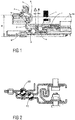
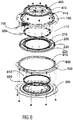
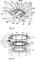
- the motor vehicle seat rotation mechanism shown in the figures comprises a connecting plate 100, a moving plate 200, a fixed plate 300, a press plate 400, an upper ball assembly 500, a lower ball assembly 600 and a locking device 700.
- An annular upper ball track 410 is provided on the press plate 400; an annular upper middle ball track 210 and an annular lower middle ball track 220 are provided on the moving plate 200; an annular lower ball track 310 is provided on the fixed plate 300.
- the connecting plate 100 is not only connected in a fixed manner to a seat (not shown in the figures), but also connected in a fixed manner to the moving plate 200 by means of rivets 910, with the moving plate 200 being located below the connecting plate 100.
- the fixed plate 300 is connected to an upper slide rail (not shown in the figures) in a seat slide rail assembly, and is located below the moving plate 200.
- the press plate 400 is located above the moving plate 200 and connected in a fixed manner to the fixed plate 300 by means of screws 920.
- the upper ball track 410 on the press plate 400 and the upper middle ball track 210 on the moving plate 200 are vertically opposite one another; upper balls 510 in the upper ball assembly 500 are located between the upper ball track 410 on the press plate 400 and the upper middle ball track 210 on the moving plate 200, and are in rolling contact with both ball tracks.
- the lower middle ball track 220 on the moving plate 200 and the lower ball track 310 on the fixed plate 300 are vertically opposite one another; lower balls 610 in the lower ball assembly 600 are located between the lower middle ball track 220 on the moving plate 200 and the lower ball track 310 on the fixed plate 300, and are in rolling contact with both ball tracks.
- a first characteristic of the motor vehicle seat rotation mechanism of the present invention is that it further comprises a lower anti-detachment hook ring 800, located between the connecting plate 100 and the fixed plate 300 and fixed to the fixed plate 300.
- An annular lower anti-detachment hook 810 having an inverted U-shape, is provided at an inner edge of the lower anti-detachment hook ring 800;
- an annular upper anti-detachment hook 230 having a U-shape, is provided at an outer edge of the moving plate 200; the lower anti-detachment hook 810 is placed over the upper anti-detachment hook 230, achieving mutual engagement.
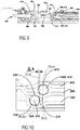
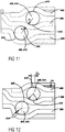
- a second characteristic of the present invention is: referring to figs. 10 and 11 , a radial separation between a perpendicular axis on which the centre of the upper ball 510 in the upper ball assembly 500 is located and a perpendicular axis on which the centre of the lower ball 610 in the lower ball assembly 600 is located, ⁇ A ⁇ 0, whereas in the known art, ⁇ A > 0.
- An advantage of such a design is that under a pressing action, the relationship between the upper ball 510 and the lower ball 610 enables two forces F1 and F2, of equal magnitude but in opposite directions, to cancel each other out, avoiding elastic deformation of travel of the ball track under cantilever action, which would in turn affect the operating precision of the motor vehicle seat rotation mechanism of the present invention.
- the tangent T510 of the upper ball 510 is in parallel with the perpendicular axis P510 of the upper ball 510 and located radially outward of the upper ball 510 with respect to the centre axis CA (shown in figure 13 ) of the arrangement of the rotation mechanism.
- the tangent T610 of the lower ball 610 is in parallel with the perpendicular axis P610 of the lower ball and located radially inwards of the lower ball 610 with respect to the centre axis CA of the arrangement of the rotation mechanism.
- the radial distance ⁇ A between the tangents T510, T610 of the upper ball 510 and the lower ball 610 is equal or less than zero.
- the adjacent upper and lower balls 510, 610 may overlap provided that the overlapping edge faces radially inwards or outwards.
- T610 are identical, in particular congruent wherein the upper and lower balls 510, 610 do not overlap.
- ⁇ A ⁇ 0 than the tangents T510, T610 are arranged in parallel with each other and with respect to the perpendicular axis P510, P610 wherein the adjacent upper and lower balls 510, 610 are partially overlapped.
- a third characteristic of the present invention is: referring to fig. 12 , when the press plate 400 is tightened by the torque of the tightening screws 920, these apply a tightening force Fs which applies pressure downwards via the upper balls 510, pushing the moving plate 200 and the lower balls 610 towards the fixed plate 300, so that even in the case where the precision with which the ball track is worked has a certain error, the upper balls 510 and lower balls 610 can support each other during movement.
- the upper ball track 410 on the press plate 400 is a flat surface ball track, a width thereof being one quarter of a diameter of the upper balls 510; this enables the upper balls 510 to have a certain amount of movement ⁇ 1.
- the upper middle ball track 210 on the moving plate 200 is a circular arc ball track; a radius R4 of the upper middle ball track 210 is greater than a radius R3 of the upper balls 510, so that under the action of the force Fs, the upper balls 510 force the moving plate 200 to move obliquely downwards to eliminate a tolerance, to a state of zero gap fitting.
- the lower ball track 310 on the fixed plate 300 of the present invention is a circular arc ball track; a radius R1 of the lower ball track 310 is less than a radius R2 of the lower balls 610, and when the upper balls 510 force the lower balls 610 to draw close to the centre of the lower ball track 310 of the fixed plate 300 by means of the lower middle ball track 220 on the moving plate 200, two-point contact is formed between each lower ball 610 and the lower ball track 310.
- a fourth characteristic of the present invention is: the locking device 700, used for locking the fixed plate 300 to the moving plate 200 when adjustment of the motor vehicle rotation mechanism is complete, is mounted on the connecting plate 100 and located in a space between the connecting plate 100 and an outer edge of the lower anti-detachment hook ring 800; using the space between the connecting plate 100 and the outer edge of the lower anti-detachment hook ring 800 to mount the locking device 700 in this way effectively reduces the height H of the motor vehicle seat rotation mechanism.
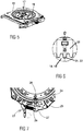
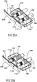
- a locking device 700 shown in the figures comprises a locking pin mounting box 710 at least having a top side 711, a first lateral side 712 and a second lateral side 713, and also comprises an unlocking handle 720, two unlocking tension springs 730, 740, two locking pins 750, 760 and two locking springs 770, 780.
- the first lateral side 712 and the second lateral side 713 are disposed opposite each other; the top side 711 is connected to a top edge of the first lateral side 712; the first lateral side 712 and the second lateral side 713 are each provided with two locking pin guide holes 712a, 712b, 713a, 713b; the locking pin guide holes 712a, 712b, 713a, 713b in the first lateral side 712 and the second lateral side 713 have a coaxial relationship with one-to-one correspondence.
- the locking pin 750 passes through the locking pin guide hole 712a in the first lateral side 712 and the locking pin guide hole 713a in the second lateral side 713; the locking pin 760 passes through the locking pin guide hole 712b in the first lateral side 712 and the locking pin guide hole 713b in the second lateral side 713.
- Spring bearing bosses 751, 761 are disposed in middle positions of both locking pins 750, 760; the two locking springs 770, 780 surround the locking pins 750, 760 respectively, with the locking springs 770, 780 each having one end in contact with the first lateral side 712, and the other ends being in contact with the spring bearing bosses 751, 761 respectively.
- a first end of the unlocking handle 720 is hinged to the top side 711 of the locking pin mounting box 710.
- a locking device mounting gap 110 is provided in a certain position on an outer periphery of the connecting plate 100; the top side 711 in the locking device 700 is inserted into the locking device mounting gap 110 and fastened by means of bolts 930.
- An obround locking hole 811 is provided at a suitable position of the lower anti-detachment hook 810 on the lower anti-detachment hook ring 800; the second ends of the locking pins 750, 760, after passing through the second lateral side 713, are simultaneously inserted into the obround locking hole 811.
- Having the locking pins 750, 760 located in the space between the connecting plate 100 and the outer edge of the lower anti-detachment hook ring 800 can further reduce the height H of the motor vehicle seat rotation mechanism.
- the locking pins 750, 760 in the locking device 700 are inserted into the locking hole 811 in the lower anti-detachment hook ring 800, to achieve locking between the connecting plate 100 and the lower anti-detachment hook ring 800. Since the connecting plate 100 is connected in a fixed manner to the moving plate 200, and the lower anti-detachment hook ring 800 is connected in a fixed manner to the fixed plate 300, locking between the moving plate 200 and the fixed plate 300 can be achieved.
- the unlocking handle 720 When it is necessary to rotate the seat, the unlocking handle 720 is lifted upward, and the two locking pins 750, 760 are pulled outward from the locking hole 811 in the lower anti-detachment hook ring 800, by means of the two unlocking tension springs 730, 740. After releasing the unlocking handle 720, the two locking pins 750, 760 can be reinserted, under the driving action of the locking springs 770, 780, into the locking hole 811 in the lower anti-detachment hook ring 800 to achieve locking.
- the two unlocking tension springs 730, 740 drive the unlocking handle 720 to its original position.
- the present invention changes the claw-type locking in the prior art to an arrangement in which the two locking pins 750, 760 can be reinserted, under the driving action of the locking springs 770, 780, into the locking hole 811 in the lower anti-detachment hook ring 800 to achieve locking.
- An advantage of this arrangement is that a hole-and-shaft fit is the form that is most convenient for machining and matching, and satisfactory precision can be attained relatively cheaply.
- the two locking pins 750, 760 of the present invention can each extend and retract independently under the driving action of the locking springs 770, 780, whereas multiple protrusions on a one-piece engaging claw "enter and exit together", and complete locking can only be achieved if all of the protrusions enter all of the recesses, so the promptness of locking is inferior to that of the present invention.
- the second ends of the two locking pins 750, 760 of the present invention are both in a retracted state and in contact with an outer surface of the lower anti-detachment hook 810 on the lower anti-detachment hook ring 800; when a locking position is reached, the locking pin 750 rotates to the position of the obround locking hole 811 first, and is inserted into the obround locking hole 811 under the pushing action of the locking spring 770; as the locking device continues to rotate relative to the fixed plate 300, the locking pin 760 also rotates to the position of the obround locking hole 811, and is inserted into the obround locking hole 811 under the pushing action of the locking spring 780.
- the present invention changes the rotary handle in the prior art to the unlocking handle 720 which is lifted upward; the extension and retraction of the two locking pins 750, 760 are controlled by the unlocking handle 720; the unlocking handle 720 is lifted manually; the unlocking handle 720 rotates anticlockwise around a hinge shaft 721 of the unlocking handle and the top side 711; and the unlocking handle 720 pulls the two locking pins 750, 760 by means of the two unlocking tension springs 730, 740 such that the two locking pins are withdrawn outward from the obround locking hole 811.
- the two locking pins 750, 760 can be reinserted, under the driving action of the locking springs 770, 780, into the locking hole 811 in the lower anti-detachment hook ring 800 to achieve locking; the structure is very simple, and the pulling-up of the unlocking handle 720 is more in conformity with the operating habits of users.
- the second ends of the two locking pins 750, 760 both have a conical structure; supposing that a length between two arc edges Ea, Eb at two ends of the obround locking hole 811 is L, a length of a line connecting guide points C, C' of the two locking pins 750, 760 is 0.8 mm less than the value of L, cone-shape starting points of the two locking pins 750, 760 are b, b', a length of a line connecting the cone-shape starting points b, b' of the two locking pins 750, 760 is 0.5 mm less than the value of L, cone-shape ending points of the two locking pins 750, 760 are a, a', a length of a line connecting the cone-shape end points a, a' of the two locking pins 750, 760 is 1.2 mm greater than the value of L; thus, under the combined action of
Landscapes
- Engineering & Computer Science (AREA)
- Aviation & Aerospace Engineering (AREA)
- Transportation (AREA)
- Mechanical Engineering (AREA)
- Seats For Vehicles (AREA)
Claims (14)
- Kraftfahrzeugsitzdrehmechanismus, der Folgendes umfasst:eine Verbindungsplatte (100), die mit einem Sitz verbunden ist;eine bewegliche Platte (200), die unter der Verbindungsplatte (100) positioniert und fest mit der Verbindungsplatte (100) verbunden ist;eine fixierte Platte (300), die unter der beweglichen Platte (200) positioniert ist, wobei die fixierte Platte (300) mit einer oberen Gleitschiene in einer Gleitschienenanordnung des Sitzes verbunden ist;eine Druckplatte (400), die über der beweglichen Platte (200) positioniert und fest mit der fixierten Platte (300) verbunden ist;eine obere Kugelanordnung (500), die zwischen der Druckplatte (400) und der beweglichen Platte (200) positioniert ist;eine untere Kugelanordnung (600), die zwischen der beweglichen Platte (200) und der fixierten Platte (300) positioniert ist;ferner dadurch gekennzeichnet, dass er Folgendes umfasst:
einen separaten unteren Lösungssicherungshakenring (800), der zwischen der Verbindungsplatte (100) und der fixierten Platte (300) positioniert und an der fixierten Platte (300) fixiert ist, wobei eine ringförmige untere Kerbe an einem Innenrand des separaten unteren Lösungssicherungshakenrings (800) zur Bildung eines ringförmigen unteren Lösungssicherungshakens (810) vorgesehen ist und eine ringförmige obere Kerbe an einem Außenrand der beweglichen Platte (200) zur Bildung eines ringförmigen oberen Lösungssicherungshakens (230) vorgesehen ist, wobei der ringförmige untere Lösungssicherungshaken (810) und der ringförmige obere Lösungssicherungshaken (230) miteinander in Eingriff stehen. - Kraftfahrzeugsitzdrehmechanismus nach Anspruch 1, dadurch gekennzeichnet, dass der untere Lösungssicherungshaken (810) die Form eines umgekehrten U aufweist, der obere Lösungssicherungshaken (230) eine U-Form aufweist und der untere Lösungssicherungshaken (810) mit der Form eines umgekehrten U über dem oberen Lösungssicherungshaken (230) mit der U-Form platziert ist.
- Kraftfahrzeugsitzdrehmechanismus nach Anspruch 1 oder 2,
dadurch gekennzeichnet, dass eine Tangente der oberen Kugel (510) parallel zu einer senkrechten Achse der oberen Kugel (510) und bezüglich einer Mittelachse des Kraftfahrzeugsitzdrehmechanismus von der oberen Kugel (510) aus radial außen positioniert ist und eine Tangente der unteren Kugel (610) zu einer senkrechten Achse der unteren Kugel (610) parallel und bezüglich der Mittelachse von der unteren Kugel (610) aus radial innen positioniert ist und ein radialer Abstand (ΔA) zwischen der senkrechten Achse der oberen Kugel (510) der oberen Kugelanordnung (500) und der senkrechten Achse der unteren Kugel (610) in der unteren Kugelanordnung (600) kleiner gleich oder kleiner null ist. - Kraftfahrzeugsitzdrehmechanismus nach einem der vorhergehenden Ansprüche, dadurch gekennzeichnet, dass eine obere Kugelschiene (410) an der Druckplatte (400) vorgesehen ist, eine obere mittlere Kugelschiene (210) und eine untere mittlere Kugelschiene (220) an der beweglichen Platte (200) vorgesehen sind und eine untere Kugelschiene an der fixierten Platte (300) vorgesehen ist, wobei die obere Kugelschiene an der Druckplatte (400) und die obere mittlere Kugelschiene (210) an der beweglichen Platte (200) einander vertikal gegenüberliegen.
- Kraftfahrzeugsitzdrehmechanismus nach Anspruch 4, wobei die obere Kugel (510) in der oberen Kugelanordnung (500) zwischen der oberen Kugelschiene (410) an der Druckplatte (400) und der oberen mittleren Kugelschiene (210) an der beweglichen Platte (200) positioniert ist und sich mit der oberen Kugelschiene (410) an der Druckplatte (400) und der oberen mittleren Kugelschiene (210) an der beweglichen Platte (200) in Rollkontakt befindet.
- Kraftfahrzeugsitzdrehmechanismus nach einem der vorhergehenden Ansprüche, wobei die untere mittlere Kugelschiene (220) an der beweglichen Platte (200) und die untere Kugelschiene an der fixierten Platte (300) einander vertikal gegenüberliegen und eine untere Kugel (610) in der unteren Kugelanordnung (600) zwischen der unteren mittleren Kugelschiene (220) an der beweglichen Platte (200) und der unteren Kugelschiene an der fixierten Platte (300) positioniert ist und sich mit der unteren mittleren Kugelschiene (220) an der beweglichen Platte (200) und der unteren Kugelschiene an der fixierten Platte (300) in Rollkontakt befindet.
- Kraftfahrzeugsitzdrehmechanismus nach Anspruch 5 oder 6, wobei die obere Kugelschiene (410) an der Druckplatte (400) eine ebenflächige Kugelschiene ist, deren Breite ein Viertel eines Durchmessers der oberen Kugel (510) beträgt.
- Kraftfahrzeugsitzdrehmechanismus nach Anspruch 6 oder 7,
wobei die obere mittlere Kugelschiene (210) an der beweglichen Platte (200) eine kreisbogenförmige Kugelschiene ist, wobei ein Radius der oberen mittleren Kugelschiene (210) größer als ein Radius der oberen Kugel (510) ist; und
die untere Kugelschiene an der fixierten Platte (300) eine kreisbogenförmige Kugelschiene ist, wobei ein Radius der unteren Kugelschiene kleiner als ein Radius der unteren Kugel (610) ist, so dass eine Zweipunktberührung zwischen der unteren Kugel (610) und der unteren Kugelschiene gebildet wird. - Kraftfahrzeugsitzdrehmechanismus nach einem der vorhergehenden Ansprüche 1-8, dadurch gekennzeichnet, dass der Kraftfahrzeugsitzdrehmechanismus ferner eine Verriegelungsvorrichtung (700) zur Verriegelung der fixierten Platte (300) mit der beweglichen Platte (200), wenn eine Einstellung des Kraftfahrzeugsitzdrehmechanismus beendet ist, umfasst; die Verriegelungsvorrichtung an der Verbindungsplatte (100) befestigt und in einem Zwischenraum zwischen der Verbindungsplatte (100) und einem Außenrand des unteren Lösungssicherungshakenrings (800) positioniert ist.
- Kraftfahrzeugsitzdrehmechanismus nach Anspruch 9, dadurch gekennzeichnet, dass die Verriegelungsvorrichtung mindestens einen Verriegelungsstift umfasst, der in dem Zwischenraum zwischen der Verbindungsplatte (750, 760) und dem Außenrand des unteren Lösungssicherungshakenrings (800) positioniert ist, und eine Verriegelungsbohrung in dem unteren Lösungssicherungshakenring (800) vorgesehen ist; wenn es nötig ist, den Sitz zu verriegeln, um zu verhindern, dass er sich dreht, wird der Verriegelungsstift (750, 760) in der Verriegelungsvorrichtung in die Verriegelungsbohrung in dem unteren Lösungssicherungshakenring (800) zur Erzielung einer Verriegelung zwischen der Verbindungsplatte (100) und dem unteren Lösungssicherungshakenring (800) und wiederum zur Erzielung einer Verriegelung zwischen der beweglichen Platte (200) und der fixierten Platte (300) eingeführt; wenn es nötig ist, den Sitz zu drehen, wird der Verriegelungsstift in der Verriegelungsvorrichtung aus der Verriegelungsbohrung in dem unteren Lösungssicherungshakenring (800) herausgezogen.
- Kraftfahrzeugsitzdrehmechanismus nach Anspruch 9 oder 10,
dadurch gekennzeichnet, dass die Verriegelungsvorrichtung ferner eine Verriegelungsstiftbefestigungsbox (710) umfasst, die mindestens eine obere Seite (711), eine erste laterale Seite (712) und eine zweite laterale Seite (713) aufweist, und auch einen Entriegelungsgriff (720) und mindestens eine Entriegelungsspannfeder (730, 740) umfasst, wobei die erste laterale Seite (712) und die zweite laterale Seite (713) einander gegenüber angeordnet sind, die obere Seite (711) mit einem oberen Rand der ersten lateralen Seite (712) verbunden ist, die erste laterale Seite (712) und die zweite laterale Seite (713) jeweils mit mindestens einer Verriegelungsstiftführungsbohrung (712a, 712b, 713a, 713b) versehen ist und die Verriegelungsstiftführungsbohrungen (712a, 712b, 713a, 713b) in der ersten lateralen Seite (712) und der zweiten lateralen Seite (713) eine koaxiale Beziehung mit Eineindeutigkeit aufweisen; der Verriegelungsstift (750, 760) durch die entsprechenden Verriegelungsstiftführungsbohrungen (712a, 712b, 713a, 713b) in der ersten lateralen Seite (712) und der zweiten lateralen Seite (713) hindurchgeht, ein Federlageransatz (751, 761) an einer mittigen Position des Verriegelungsstifts (750, 760) vorgesehen ist und eine Verriegelungsfeder (770, 780) den Verriegelungsstift (750, 760) umgibt, wobei die Verriegelungsfeder (770, 780) ein Ende in Kontakt mit der ersten lateralen Seite (712) und ein anderes Ende in Kontakt mit dem Federlageransatz (751, 761) aufweist; ein erstes Ende des Verriegelungsstifts (750, 760) nach dem Hindurchgehen durch die erste laterale Seite (712) mit dem Entriegelungsgriff (720) durch die Entriegelungsspannfeder (730, 740) verbunden ist und ein zweites Ende des Verriegelungsstifts (750, 760) nach dem Hindurchgehen durch die zweite laterale Seite (713) in die Verriegelungsbohrung in dem unteren Lösungssicherungshakenring (800) in einem verriegelten Zustand eingeführt ist; ein erstes Ende des Entriegelungsgriffs (720) an der oberen Seite (711) der Verriegelungsstiftbefestigungsbox (710) angelenkt ist und die obere Seite der Verriegelungsstiftbefestigungsbox (710) an der Verbindungsplatte (100) fest befestigt ist. - Kraftfahrzeugsitzdrehmechanismus nach Anspruch 11, dadurch gekennzeichnet, dass das zweite Ende des Verriegelungsstifts (750, 760) eine konische Struktur aufweist.
- Kraftfahrzeugsitzdrehmechanismus nach Anspruch 12, dadurch gekennzeichnet, dass es zwei Verriegelungsstifte (750, 760) gibt, die Verriegelungsbohrung (811) in dem unteren Lösungssicherungshakenring (800) eine länglich-runde Verriegelungsbohrung (811) ist die zwei Verriegelungsstifte (750, 760) gleichzeitig in die länglich-runde Verriegelungsbohrung (811) eingeführt sind und konische Flächen der zwei Verriegelungsstifte (750, 760) in engem Kontakt mit Bogenrändern an zwei Enden der länglich-runden Verriegelungsbohrung (811) sind.
- Kraftfahrzeugsitzdrehmechanismus nach einem der vorhergehenden Ansprüche, dadurch gekennzeichnet, dass:
eine Verriegelungsvorrichtung (700), die zur Verriegelung der fixierten Platte (300) an der beweglichen Platte (200), wenn eine Einstellung des Kraftfahrzeugsitzdrehmechanismus beendet ist, verwendet wird, an der Verbindungsplatte (100) befestigt und in einem Zwischenraum zwischen der Verbindungsplatte (100) und dem Außenrand des unteren Lösungssicherungshakenrings (800) befestigt ist; unter Verwendung des Zwischenraums zwischen der Verbindungsplatte (100) und dem Außenrand des unteren Lösungssicherungshakenrings (800).
Applications Claiming Priority (1)
| Application Number | Priority Date | Filing Date | Title |
|---|---|---|---|
| CN201711218807.2A CN107953806B (zh) | 2017-11-28 | 2017-11-28 | 一种汽车座椅旋转机构 |
Publications (2)
| Publication Number | Publication Date |
|---|---|
| EP3489079A1 EP3489079A1 (de) | 2019-05-29 |
| EP3489079B1 true EP3489079B1 (de) | 2021-09-08 |
Family
ID=61962313
Family Applications (1)
| Application Number | Title | Priority Date | Filing Date |
|---|---|---|---|
| EP18208624.9A Active EP3489079B1 (de) | 2017-11-28 | 2018-11-27 | Kraftfahrzeugsitzdrehmechanismus |
Country Status (4)
| Country | Link |
|---|---|
| US (1) | US10688889B2 (de) |
| EP (1) | EP3489079B1 (de) |
| JP (1) | JP6650989B2 (de) |
| CN (1) | CN107953806B (de) |
Cited By (1)
| Publication number | Priority date | Publication date | Assignee | Title |
|---|---|---|---|---|
| KR20240118491A (ko) * | 2023-01-27 | 2024-08-05 | 현대트랜시스 주식회사 | 자동차용 시트 스위블 장치 |
Families Citing this family (35)
| Publication number | Priority date | Publication date | Assignee | Title |
|---|---|---|---|---|
| CN207725260U (zh) * | 2017-11-28 | 2018-08-14 | 延锋安道拓座椅有限公司 | 一种锁止装置 |
| CN209474126U (zh) * | 2018-07-27 | 2019-10-11 | 延锋安道拓座椅有限公司 | 一种旋转座椅无间隙锁止机构 |
| CN108968465B (zh) * | 2018-07-27 | 2024-07-30 | 延锋国际座椅系统有限公司 | 一种座椅旋转锁止机构 |
| CN109050356A (zh) * | 2018-08-10 | 2018-12-21 | 重庆杜米亚柯科技有限公司 | 一种汽车座椅转盘结构 |
| CN109823239B (zh) | 2019-02-14 | 2023-03-10 | 延锋国际座椅系统有限公司 | 汽车座椅电动旋转装置 |
| CN109677302B (zh) * | 2019-02-14 | 2020-08-28 | 延锋安道拓座椅有限公司 | 用于车辆座椅的转动装置 |
| CN110406434B (zh) * | 2019-06-17 | 2024-06-07 | 广汽零部件有限公司 | 一种汽车座椅滑轨机构 |
| CN110384355B (zh) * | 2019-07-19 | 2022-05-27 | 开封大学 | 一种可变形与组合的工作座椅 |
| DE102019124672B3 (de) * | 2019-09-13 | 2021-02-04 | Isringhausen Gmbh & Co. Kg | Dreheinheit für einen um seine Hochachse rotierbaren Fahrzeugsitz, Crashhaken für eine solche Dreheinheit und rotierbarer Fahrzeugsitz |
| CN110435498B (zh) * | 2019-09-23 | 2024-04-19 | 麦格纳汽车技术(上海)有限公司徐汇分公司 | 可调节旋转力的座椅旋转机构 |
| CN110626230B (zh) * | 2019-10-31 | 2025-07-25 | 湖北航嘉麦格纳座椅系统有限公司 | 汽车座椅及座椅旋转机构 |
| CN113619454A (zh) * | 2020-05-06 | 2021-11-09 | 威马智慧出行科技(上海)有限公司 | 座椅结构及汽车 |
| CN112026625B (zh) * | 2020-09-10 | 2021-07-23 | 惠安县螺阳林飞燕汽车维修中心 | 一种户外抢修车 |
| US11772517B2 (en) | 2020-11-09 | 2023-10-03 | Ford Global Technologies, Llc | Vehicular system capable of adjusting a passenger compartment from a child seat arrangement to a second arrangement |
| US11772519B2 (en) | 2020-11-09 | 2023-10-03 | Ford Global Technologies, Llc | Vehicular system capable of adjusting a passenger compartment from a first arrangement to a child seat arrangement |
| US12257932B2 (en) | 2020-11-09 | 2025-03-25 | Ford Global Technologies, Llc | Exterior imager utilized in adjusting a passenger compartment arrangement |
| US11731535B2 (en) | 2020-11-09 | 2023-08-22 | Ford Global Technologies, Llc | Vehicular system capable of adjusting a passenger compartment from a child care arrangement to a second arrangement |
| US11772520B2 (en) | 2020-11-09 | 2023-10-03 | Ford Global Technologies, Llc | Remote notification and adjustment of a passenger compartment arrangement |
| US12077068B2 (en) | 2020-11-09 | 2024-09-03 | Ford Global Technologies, Llc | Authorization-based adjustment of passenger compartment arrangement |
| US11904732B2 (en) | 2020-11-09 | 2024-02-20 | Ford Global Technologies, Llc | Vehicular system capable of adjusting a passenger compartment from a first arrangement to a child care arrangement |
| CN112674530A (zh) * | 2021-01-25 | 2021-04-20 | 嘉兴市领地家具用品有限公司 | 一种座框 |
| CN112848979A (zh) * | 2021-02-19 | 2021-05-28 | 上海东尚机械科技有限责任公司 | 一种汽车座椅手动转动系统 |
| CN113147529B (zh) * | 2021-04-25 | 2024-08-16 | 长春一汽富维安道拓汽车金属零部件有限公司 | 一种手动解锁的汽车旋转座椅 |
| CN113135129B (zh) * | 2021-05-14 | 2022-09-27 | 东风汽车集团股份有限公司 | 一种可手动电动调节的旋转座椅和汽车 |
| US12104744B2 (en) * | 2022-06-01 | 2024-10-01 | Jinyan Duan | Turner apparatus |
| US12196358B2 (en) * | 2021-09-26 | 2025-01-14 | Xiaoling CHE | Rotating assembly |
| CN113829966A (zh) * | 2021-11-08 | 2021-12-24 | 重庆飞适动力汽车座椅部件有限公司 | 一种用于车辆座椅的内外滑轨防脱装置 |
| US12128807B2 (en) | 2022-03-21 | 2024-10-29 | Ford Global Technologies, Llc | Seat-mounted work surface |
| US12030409B2 (en) | 2022-03-21 | 2024-07-09 | Ford Global Technologies, Llc | Seating assembly with swivel capability |
| US11919361B2 (en) | 2022-03-21 | 2024-03-05 | Ford Global Technologies, Llc | Vehicle floor panel |
| KR102710068B1 (ko) * | 2022-04-11 | 2024-09-26 | 대원산업 주식회사 | 차량용 스위블장치 |
| USD1110749S1 (en) * | 2022-06-27 | 2026-02-03 | Williams-Sonoma, Inc. | Seat and backrest |
| US11904737B2 (en) | 2022-07-15 | 2024-02-20 | Ford Global Technologies, Llc | Seating assembly with swivel capability |
| CN115384375A (zh) * | 2022-09-29 | 2022-11-25 | 湖北中航精机科技有限公司 | 一种头枕结构和座椅 |
| CN220764153U (zh) * | 2023-09-12 | 2024-04-12 | 湖北中航精机科技有限公司 | 一种座椅转盘机构和车辆 |
Family Cites Families (19)
| Publication number | Priority date | Publication date | Assignee | Title |
|---|---|---|---|---|
| US3338622A (en) | 1965-12-08 | 1967-08-29 | Chrysler Corp | Swivel seat for motor vehicle |
| DE4203150A1 (de) * | 1992-02-05 | 1993-08-12 | Keiper Recaro Gmbh Co | Dreheinrichtung fuer fahrzeugsitze, insbesondere kraftfahrzeugsitze |
| CN2253143Y (zh) * | 1995-06-06 | 1997-04-30 | 上海旭卡机械电器有限公司 | 改进的旋转座 |
| JP3451910B2 (ja) | 1996-12-16 | 2003-09-29 | トヨタ車体株式会社 | 車両用シ−トの回転装置 |
| EP0847893B1 (de) * | 1996-12-16 | 2006-03-01 | Toyota Shatai Kabushiki Kaisha | Schwenkbare Anordnung für Fahrzeugsitze |
| US6021989A (en) * | 1996-12-16 | 2000-02-08 | Toyota Shatai Kabushiki Kaisha | Swivel assembly of a vehicle seat |
| JPH10217811A (ja) * | 1997-02-10 | 1998-08-18 | Toyota Auto Body Co Ltd | シート回転装置 |
| JP3570363B2 (ja) | 2000-08-31 | 2004-09-29 | ジョンソン コントロールズ オートモーティブ システムズ株式会社 | 車両用シートの回転調整機構 |
| DE60118068T2 (de) * | 2000-08-31 | 2006-08-17 | Johnson Controls Automotive Systems Corp., Ayase | Dreh- und Verstellmechanismus für Fahrzeugsitz |
| US7661646B2 (en) * | 2003-08-27 | 2010-02-16 | Intier Automotive Inc. | Locking mechanism for seat track assembly |
| JP4305675B2 (ja) | 2007-03-02 | 2009-07-29 | トヨタ車体株式会社 | 車両用シート |
| DE102012112523B4 (de) * | 2012-12-18 | 2020-11-12 | Grammer Aktiengesellschaft | Nutzfahrzeugsitz mit drehbarem Sitzteil |
| DE102012112527B3 (de) * | 2012-12-18 | 2014-06-05 | Grammer Ag | Nutzfahrzeugsitz mit integrierter Drehverstelleinrichtung |
| DE102012112528B4 (de) * | 2012-12-18 | 2014-09-18 | Grammer Ag | Nutzfahrzeugsitz mit einer Drehverstelleinrichtung-Überlastsicherungseinheit |
| DE102012112529B3 (de) * | 2012-12-18 | 2014-03-20 | Grammer Ag | Nutzfahrzeugsitz mit einem Verriegelungselement |
| CN203974597U (zh) * | 2014-07-18 | 2014-12-03 | 重庆延锋江森汽车部件系统有限公司 | 汽车座椅滑轨 |
| CN105416104B (zh) * | 2015-12-14 | 2018-02-16 | 襄阳寒桦精机有限公司 | 一种车辆座椅装置 |
| CN206186835U (zh) | 2016-11-24 | 2017-05-24 | 江苏忠明祥和精工股份有限公司 | 汽车座椅用转盘 |
| CN106427682A (zh) * | 2016-11-24 | 2017-02-22 | 江苏忠明祥和精工股份有限公司 | 汽车座椅用转盘 |
-
2017
- 2017-11-28 CN CN201711218807.2A patent/CN107953806B/zh active Active
-
2018
- 2018-11-26 JP JP2018219925A patent/JP6650989B2/ja active Active
- 2018-11-27 EP EP18208624.9A patent/EP3489079B1/de active Active
- 2018-11-27 US US16/201,010 patent/US10688889B2/en active Active
Cited By (1)
| Publication number | Priority date | Publication date | Assignee | Title |
|---|---|---|---|---|
| KR20240118491A (ko) * | 2023-01-27 | 2024-08-05 | 현대트랜시스 주식회사 | 자동차용 시트 스위블 장치 |
Also Published As
| Publication number | Publication date |
|---|---|
| JP2019099144A (ja) | 2019-06-24 |
| EP3489079A1 (de) | 2019-05-29 |
| CN107953806A (zh) | 2018-04-24 |
| US20190160977A1 (en) | 2019-05-30 |
| CN107953806B (zh) | 2020-04-07 |
| JP6650989B2 (ja) | 2020-02-19 |
| US10688889B2 (en) | 2020-06-23 |
Similar Documents
| Publication | Publication Date | Title |
|---|---|---|
| EP3489079B1 (de) | Kraftfahrzeugsitzdrehmechanismus | |
| EP3489080B1 (de) | Verriegelungsvorrichtung und kraftfahrzeugsitzdrehmechanismus | |
| US8720999B2 (en) | Fitting for a vehicle seat | |
| US5873630A (en) | Rotary-cam type reclining device | |
| EP4194240B1 (de) | Verriegelungsmechanismus, batteriehalterung, elektrofahrzeug und verfahren zum verriegeln und entriegeln eines batteriepacks | |
| US7926858B2 (en) | Lock device | |
| US7703852B2 (en) | Heavy duty reclining mechanism for vehicle seats | |
| US20060022503A1 (en) | Hinge mechanism for a vehicle seat, and a seat including such a mechanism | |
| EP2646281B1 (de) | Beschlag für einen fahrzeugsitz | |
| JP2010173491A (ja) | 車両用回転シート装置 | |
| EP3246245B1 (de) | Klappflügelspitze und rotierendes verriegelungselement | |
| EP3103653A1 (de) | Rollfuss mit doppelter verriegelung | |
| KR20150130306A (ko) | 테이퍼형 핀 캠 표면을 갖는 디스크 리클라이너 | |
| US20100219037A1 (en) | Bidirectional self-locking device | |
| EP3774541A1 (de) | Nutzlastbefestigungsbeschlag und verfahren zur verwendung davon | |
| CN103534137A (zh) | 双凸轮倾角调节器 | |
| US8960797B2 (en) | Latch fitting for locking two vehicle components | |
| EP3931041B1 (de) | Rastbeschlag für einen fahrzeugsitz | |
| CN101554850B (zh) | 有靠背的汽车座椅和有这种汽车座椅的座席装置 | |
| US20060028057A1 (en) | Locking mechanism with rotatable features | |
| JP5434101B2 (ja) | 車両用回転シート装置 | |
| US10787102B2 (en) | Recliner mechanism | |
| US20130051899A1 (en) | Detent fitting for locking two vehicle parts | |
| US20230193664A1 (en) | Door latch jamming assembly | |
| EP3685050B1 (de) | Drehausrichtungsvorrichtung für einen aktuator |
Legal Events
| Date | Code | Title | Description |
|---|---|---|---|
| PUAI | Public reference made under article 153(3) epc to a published international application that has entered the european phase |
Free format text: ORIGINAL CODE: 0009012 |
|
| STAA | Information on the status of an ep patent application or granted ep patent |
Free format text: STATUS: THE APPLICATION HAS BEEN PUBLISHED |
|
| AK | Designated contracting states |
Kind code of ref document: A1 Designated state(s): AL AT BE BG CH CY CZ DE DK EE ES FI FR GB GR HR HU IE IS IT LI LT LU LV MC MK MT NL NO PL PT RO RS SE SI SK SM TR |
|
| AX | Request for extension of the european patent |
Extension state: BA ME |
|
| STAA | Information on the status of an ep patent application or granted ep patent |
Free format text: STATUS: REQUEST FOR EXAMINATION WAS MADE |
|
| 17P | Request for examination filed |
Effective date: 20191129 |
|
| RBV | Designated contracting states (corrected) |
Designated state(s): AL AT BE BG CH CY CZ DE DK EE ES FI FR GB GR HR HU IE IS IT LI LT LU LV MC MK MT NL NO PL PT RO RS SE SI SK SM TR |
|
| STAA | Information on the status of an ep patent application or granted ep patent |
Free format text: STATUS: EXAMINATION IS IN PROGRESS |
|
| 17Q | First examination report despatched |
Effective date: 20200602 |
|
| GRAP | Despatch of communication of intention to grant a patent |
Free format text: ORIGINAL CODE: EPIDOSNIGR1 |
|
| STAA | Information on the status of an ep patent application or granted ep patent |
Free format text: STATUS: GRANT OF PATENT IS INTENDED |
|
| INTG | Intention to grant announced |
Effective date: 20210413 |
|
| GRAS | Grant fee paid |
Free format text: ORIGINAL CODE: EPIDOSNIGR3 |
|
| GRAA | (expected) grant |
Free format text: ORIGINAL CODE: 0009210 |
|
| STAA | Information on the status of an ep patent application or granted ep patent |
Free format text: STATUS: THE PATENT HAS BEEN GRANTED |
|
| AK | Designated contracting states |
Kind code of ref document: B1 Designated state(s): AL AT BE BG CH CY CZ DE DK EE ES FI FR GB GR HR HU IE IS IT LI LT LU LV MC MK MT NL NO PL PT RO RS SE SI SK SM TR |
|
| REG | Reference to a national code |
Ref country code: GB Ref legal event code: FG4D |
|
| REG | Reference to a national code |
Ref country code: CH Ref legal event code: EP Ref country code: AT Ref legal event code: REF Ref document number: 1428303 Country of ref document: AT Kind code of ref document: T Effective date: 20210915 |
|
| REG | Reference to a national code |
Ref country code: DE Ref legal event code: R096 Ref document number: 602018023173 Country of ref document: DE |
|
| REG | Reference to a national code |
Ref country code: IE Ref legal event code: FG4D |
|
| REG | Reference to a national code |
Ref country code: LT Ref legal event code: MG9D |
|
| REG | Reference to a national code |
Ref country code: NL Ref legal event code: MP Effective date: 20210908 |
|
| PG25 | Lapsed in a contracting state [announced via postgrant information from national office to epo] |
Ref country code: SE Free format text: LAPSE BECAUSE OF FAILURE TO SUBMIT A TRANSLATION OF THE DESCRIPTION OR TO PAY THE FEE WITHIN THE PRESCRIBED TIME-LIMIT Effective date: 20210908 Ref country code: RS Free format text: LAPSE BECAUSE OF FAILURE TO SUBMIT A TRANSLATION OF THE DESCRIPTION OR TO PAY THE FEE WITHIN THE PRESCRIBED TIME-LIMIT Effective date: 20210908 Ref country code: HR Free format text: LAPSE BECAUSE OF FAILURE TO SUBMIT A TRANSLATION OF THE DESCRIPTION OR TO PAY THE FEE WITHIN THE PRESCRIBED TIME-LIMIT Effective date: 20210908 Ref country code: ES Free format text: LAPSE BECAUSE OF FAILURE TO SUBMIT A TRANSLATION OF THE DESCRIPTION OR TO PAY THE FEE WITHIN THE PRESCRIBED TIME-LIMIT Effective date: 20210908 Ref country code: FI Free format text: LAPSE BECAUSE OF FAILURE TO SUBMIT A TRANSLATION OF THE DESCRIPTION OR TO PAY THE FEE WITHIN THE PRESCRIBED TIME-LIMIT Effective date: 20210908 Ref country code: NO Free format text: LAPSE BECAUSE OF FAILURE TO SUBMIT A TRANSLATION OF THE DESCRIPTION OR TO PAY THE FEE WITHIN THE PRESCRIBED TIME-LIMIT Effective date: 20211208 Ref country code: BG Free format text: LAPSE BECAUSE OF FAILURE TO SUBMIT A TRANSLATION OF THE DESCRIPTION OR TO PAY THE FEE WITHIN THE PRESCRIBED TIME-LIMIT Effective date: 20211208 Ref country code: LT Free format text: LAPSE BECAUSE OF FAILURE TO SUBMIT A TRANSLATION OF THE DESCRIPTION OR TO PAY THE FEE WITHIN THE PRESCRIBED TIME-LIMIT Effective date: 20210908 |
|
| REG | Reference to a national code |
Ref country code: AT Ref legal event code: MK05 Ref document number: 1428303 Country of ref document: AT Kind code of ref document: T Effective date: 20210908 |
|
| PG25 | Lapsed in a contracting state [announced via postgrant information from national office to epo] |
Ref country code: LV Free format text: LAPSE BECAUSE OF FAILURE TO SUBMIT A TRANSLATION OF THE DESCRIPTION OR TO PAY THE FEE WITHIN THE PRESCRIBED TIME-LIMIT Effective date: 20210908 Ref country code: GR Free format text: LAPSE BECAUSE OF FAILURE TO SUBMIT A TRANSLATION OF THE DESCRIPTION OR TO PAY THE FEE WITHIN THE PRESCRIBED TIME-LIMIT Effective date: 20211209 |
|
| PG25 | Lapsed in a contracting state [announced via postgrant information from national office to epo] |
Ref country code: AT Free format text: LAPSE BECAUSE OF FAILURE TO SUBMIT A TRANSLATION OF THE DESCRIPTION OR TO PAY THE FEE WITHIN THE PRESCRIBED TIME-LIMIT Effective date: 20210908 |
|
| PG25 | Lapsed in a contracting state [announced via postgrant information from national office to epo] |
Ref country code: IS Free format text: LAPSE BECAUSE OF FAILURE TO SUBMIT A TRANSLATION OF THE DESCRIPTION OR TO PAY THE FEE WITHIN THE PRESCRIBED TIME-LIMIT Effective date: 20220108 Ref country code: SM Free format text: LAPSE BECAUSE OF FAILURE TO SUBMIT A TRANSLATION OF THE DESCRIPTION OR TO PAY THE FEE WITHIN THE PRESCRIBED TIME-LIMIT Effective date: 20210908 Ref country code: SK Free format text: LAPSE BECAUSE OF FAILURE TO SUBMIT A TRANSLATION OF THE DESCRIPTION OR TO PAY THE FEE WITHIN THE PRESCRIBED TIME-LIMIT Effective date: 20210908 Ref country code: RO Free format text: LAPSE BECAUSE OF FAILURE TO SUBMIT A TRANSLATION OF THE DESCRIPTION OR TO PAY THE FEE WITHIN THE PRESCRIBED TIME-LIMIT Effective date: 20210908 Ref country code: PT Free format text: LAPSE BECAUSE OF FAILURE TO SUBMIT A TRANSLATION OF THE DESCRIPTION OR TO PAY THE FEE WITHIN THE PRESCRIBED TIME-LIMIT Effective date: 20220110 Ref country code: PL Free format text: LAPSE BECAUSE OF FAILURE TO SUBMIT A TRANSLATION OF THE DESCRIPTION OR TO PAY THE FEE WITHIN THE PRESCRIBED TIME-LIMIT Effective date: 20210908 Ref country code: NL Free format text: LAPSE BECAUSE OF FAILURE TO SUBMIT A TRANSLATION OF THE DESCRIPTION OR TO PAY THE FEE WITHIN THE PRESCRIBED TIME-LIMIT Effective date: 20210908 Ref country code: EE Free format text: LAPSE BECAUSE OF FAILURE TO SUBMIT A TRANSLATION OF THE DESCRIPTION OR TO PAY THE FEE WITHIN THE PRESCRIBED TIME-LIMIT Effective date: 20210908 Ref country code: CZ Free format text: LAPSE BECAUSE OF FAILURE TO SUBMIT A TRANSLATION OF THE DESCRIPTION OR TO PAY THE FEE WITHIN THE PRESCRIBED TIME-LIMIT Effective date: 20210908 Ref country code: AL Free format text: LAPSE BECAUSE OF FAILURE TO SUBMIT A TRANSLATION OF THE DESCRIPTION OR TO PAY THE FEE WITHIN THE PRESCRIBED TIME-LIMIT Effective date: 20210908 |
|
| REG | Reference to a national code |
Ref country code: DE Ref legal event code: R097 Ref document number: 602018023173 Country of ref document: DE |
|
| RAP2 | Party data changed (patent owner data changed or rights of a patent transferred) |
Owner name: ADIENT US LLC |
|
| PG25 | Lapsed in a contracting state [announced via postgrant information from national office to epo] |
Ref country code: MC Free format text: LAPSE BECAUSE OF FAILURE TO SUBMIT A TRANSLATION OF THE DESCRIPTION OR TO PAY THE FEE WITHIN THE PRESCRIBED TIME-LIMIT Effective date: 20210908 |
|
| REG | Reference to a national code |
Ref country code: CH Ref legal event code: PL |
|
| PLBE | No opposition filed within time limit |
Free format text: ORIGINAL CODE: 0009261 |
|
| STAA | Information on the status of an ep patent application or granted ep patent |
Free format text: STATUS: NO OPPOSITION FILED WITHIN TIME LIMIT |
|
| REG | Reference to a national code |
Ref country code: DE Ref legal event code: R081 Ref document number: 602018023173 Country of ref document: DE Owner name: ADIENT US LLC, PLYMOUTH, US Free format text: FORMER OWNER: ADIENT ENGINEERING AND IP GMBH, 51399 BURSCHEID, DE |
|
| PG25 | Lapsed in a contracting state [announced via postgrant information from national office to epo] |
Ref country code: LU Free format text: LAPSE BECAUSE OF NON-PAYMENT OF DUE FEES Effective date: 20211127 Ref country code: DK Free format text: LAPSE BECAUSE OF FAILURE TO SUBMIT A TRANSLATION OF THE DESCRIPTION OR TO PAY THE FEE WITHIN THE PRESCRIBED TIME-LIMIT Effective date: 20210908 Ref country code: BE Free format text: LAPSE BECAUSE OF NON-PAYMENT OF DUE FEES Effective date: 20211130 |
|
| REG | Reference to a national code |
Ref country code: BE Ref legal event code: MM Effective date: 20211130 |
|
| 26N | No opposition filed |
Effective date: 20220609 |
|
| PG25 | Lapsed in a contracting state [announced via postgrant information from national office to epo] |
Ref country code: SI Free format text: LAPSE BECAUSE OF FAILURE TO SUBMIT A TRANSLATION OF THE DESCRIPTION OR TO PAY THE FEE WITHIN THE PRESCRIBED TIME-LIMIT Effective date: 20210908 Ref country code: LI Free format text: LAPSE BECAUSE OF NON-PAYMENT OF DUE FEES Effective date: 20211130 Ref country code: CH Free format text: LAPSE BECAUSE OF NON-PAYMENT OF DUE FEES Effective date: 20211130 |
|
| PG25 | Lapsed in a contracting state [announced via postgrant information from national office to epo] |
Ref country code: IE Free format text: LAPSE BECAUSE OF NON-PAYMENT OF DUE FEES Effective date: 20211127 |
|
| PG25 | Lapsed in a contracting state [announced via postgrant information from national office to epo] |
Ref country code: IT Free format text: LAPSE BECAUSE OF FAILURE TO SUBMIT A TRANSLATION OF THE DESCRIPTION OR TO PAY THE FEE WITHIN THE PRESCRIBED TIME-LIMIT Effective date: 20210908 |
|
| PG25 | Lapsed in a contracting state [announced via postgrant information from national office to epo] |
Ref country code: CY Free format text: LAPSE BECAUSE OF FAILURE TO SUBMIT A TRANSLATION OF THE DESCRIPTION OR TO PAY THE FEE WITHIN THE PRESCRIBED TIME-LIMIT Effective date: 20210908 |
|
| GBPC | Gb: european patent ceased through non-payment of renewal fee |
Effective date: 20221127 |
|
| PG25 | Lapsed in a contracting state [announced via postgrant information from national office to epo] |
Ref country code: HU Free format text: LAPSE BECAUSE OF FAILURE TO SUBMIT A TRANSLATION OF THE DESCRIPTION OR TO PAY THE FEE WITHIN THE PRESCRIBED TIME-LIMIT; INVALID AB INITIO Effective date: 20181127 |
|
| PG25 | Lapsed in a contracting state [announced via postgrant information from national office to epo] |
Ref country code: GB Free format text: LAPSE BECAUSE OF NON-PAYMENT OF DUE FEES Effective date: 20221127 |
|
| PG25 | Lapsed in a contracting state [announced via postgrant information from national office to epo] |
Ref country code: MK Free format text: LAPSE BECAUSE OF FAILURE TO SUBMIT A TRANSLATION OF THE DESCRIPTION OR TO PAY THE FEE WITHIN THE PRESCRIBED TIME-LIMIT Effective date: 20210908 |
|
| PG25 | Lapsed in a contracting state [announced via postgrant information from national office to epo] |
Ref country code: MT Free format text: LAPSE BECAUSE OF FAILURE TO SUBMIT A TRANSLATION OF THE DESCRIPTION OR TO PAY THE FEE WITHIN THE PRESCRIBED TIME-LIMIT Effective date: 20210908 |
|
| REG | Reference to a national code |
Ref country code: DE Ref legal event code: R082 Ref document number: 602018023173 Country of ref document: DE Representative=s name: LIEDTKE & PARTNER PATENTANWAELTE, DE |
|
| PG25 | Lapsed in a contracting state [announced via postgrant information from national office to epo] |
Ref country code: TR Free format text: LAPSE BECAUSE OF FAILURE TO SUBMIT A TRANSLATION OF THE DESCRIPTION OR TO PAY THE FEE WITHIN THE PRESCRIBED TIME-LIMIT Effective date: 20210908 |
|
| PGFP | Annual fee paid to national office [announced via postgrant information from national office to epo] |
Ref country code: DE Payment date: 20251128 Year of fee payment: 8 |
|
| PGFP | Annual fee paid to national office [announced via postgrant information from national office to epo] |
Ref country code: FR Payment date: 20251125 Year of fee payment: 8 |