EP3486349B1 - Metallbeschichteter stahlstreifen - Google Patents
Metallbeschichteter stahlstreifen Download PDFInfo
- Publication number
- EP3486349B1 EP3486349B1 EP18212939.5A EP18212939A EP3486349B1 EP 3486349 B1 EP3486349 B1 EP 3486349B1 EP 18212939 A EP18212939 A EP 18212939A EP 3486349 B1 EP3486349 B1 EP 3486349B1
- Authority
- EP
- European Patent Office
- Prior art keywords
- bath
- composition
- alloy
- ppm
- molten
- Prior art date
- Legal status (The legal status is an assumption and is not a legal conclusion. Google has not performed a legal analysis and makes no representation as to the accuracy of the status listed.)
- Active
Links
Images




Classifications
-
- C—CHEMISTRY; METALLURGY
- C22—METALLURGY; FERROUS OR NON-FERROUS ALLOYS; TREATMENT OF ALLOYS OR NON-FERROUS METALS
- C22C—ALLOYS
- C22C18/00—Alloys based on zinc
- C22C18/04—Alloys based on zinc with aluminium as the next major constituent
-
- C—CHEMISTRY; METALLURGY
- C22—METALLURGY; FERROUS OR NON-FERROUS ALLOYS; TREATMENT OF ALLOYS OR NON-FERROUS METALS
- C22C—ALLOYS
- C22C21/00—Alloys based on aluminium
- C22C21/10—Alloys based on aluminium with zinc as the next major constituent
-
- C—CHEMISTRY; METALLURGY
- C23—COATING METALLIC MATERIAL; COATING MATERIAL WITH METALLIC MATERIAL; CHEMICAL SURFACE TREATMENT; DIFFUSION TREATMENT OF METALLIC MATERIAL; COATING BY VACUUM EVAPORATION, BY SPUTTERING, BY ION IMPLANTATION OR BY CHEMICAL VAPOUR DEPOSITION, IN GENERAL; INHIBITING CORROSION OF METALLIC MATERIAL OR INCRUSTATION IN GENERAL
- C23C—COATING METALLIC MATERIAL; COATING MATERIAL WITH METALLIC MATERIAL; SURFACE TREATMENT OF METALLIC MATERIAL BY DIFFUSION INTO THE SURFACE, BY CHEMICAL CONVERSION OR SUBSTITUTION; COATING BY VACUUM EVAPORATION, BY SPUTTERING, BY ION IMPLANTATION OR BY CHEMICAL VAPOUR DEPOSITION, IN GENERAL
- C23C2/00—Hot-dipping or immersion processes for applying the coating material in the molten state without affecting the shape; Apparatus therefor
- C23C2/04—Hot-dipping or immersion processes for applying the coating material in the molten state without affecting the shape; Apparatus therefor characterised by the coating material
-
- C—CHEMISTRY; METALLURGY
- C23—COATING METALLIC MATERIAL; COATING MATERIAL WITH METALLIC MATERIAL; CHEMICAL SURFACE TREATMENT; DIFFUSION TREATMENT OF METALLIC MATERIAL; COATING BY VACUUM EVAPORATION, BY SPUTTERING, BY ION IMPLANTATION OR BY CHEMICAL VAPOUR DEPOSITION, IN GENERAL; INHIBITING CORROSION OF METALLIC MATERIAL OR INCRUSTATION IN GENERAL
- C23C—COATING METALLIC MATERIAL; COATING MATERIAL WITH METALLIC MATERIAL; SURFACE TREATMENT OF METALLIC MATERIAL BY DIFFUSION INTO THE SURFACE, BY CHEMICAL CONVERSION OR SUBSTITUTION; COATING BY VACUUM EVAPORATION, BY SPUTTERING, BY ION IMPLANTATION OR BY CHEMICAL VAPOUR DEPOSITION, IN GENERAL
- C23C2/00—Hot-dipping or immersion processes for applying the coating material in the molten state without affecting the shape; Apparatus therefor
- C23C2/04—Hot-dipping or immersion processes for applying the coating material in the molten state without affecting the shape; Apparatus therefor characterised by the coating material
- C23C2/06—Zinc or cadmium or alloys based thereon
-
- C—CHEMISTRY; METALLURGY
- C23—COATING METALLIC MATERIAL; COATING MATERIAL WITH METALLIC MATERIAL; CHEMICAL SURFACE TREATMENT; DIFFUSION TREATMENT OF METALLIC MATERIAL; COATING BY VACUUM EVAPORATION, BY SPUTTERING, BY ION IMPLANTATION OR BY CHEMICAL VAPOUR DEPOSITION, IN GENERAL; INHIBITING CORROSION OF METALLIC MATERIAL OR INCRUSTATION IN GENERAL
- C23C—COATING METALLIC MATERIAL; COATING MATERIAL WITH METALLIC MATERIAL; SURFACE TREATMENT OF METALLIC MATERIAL BY DIFFUSION INTO THE SURFACE, BY CHEMICAL CONVERSION OR SUBSTITUTION; COATING BY VACUUM EVAPORATION, BY SPUTTERING, BY ION IMPLANTATION OR BY CHEMICAL VAPOUR DEPOSITION, IN GENERAL
- C23C2/00—Hot-dipping or immersion processes for applying the coating material in the molten state without affecting the shape; Apparatus therefor
- C23C2/04—Hot-dipping or immersion processes for applying the coating material in the molten state without affecting the shape; Apparatus therefor characterised by the coating material
- C23C2/12—Aluminium or alloys based thereon
-
- C—CHEMISTRY; METALLURGY
- C23—COATING METALLIC MATERIAL; COATING MATERIAL WITH METALLIC MATERIAL; CHEMICAL SURFACE TREATMENT; DIFFUSION TREATMENT OF METALLIC MATERIAL; COATING BY VACUUM EVAPORATION, BY SPUTTERING, BY ION IMPLANTATION OR BY CHEMICAL VAPOUR DEPOSITION, IN GENERAL; INHIBITING CORROSION OF METALLIC MATERIAL OR INCRUSTATION IN GENERAL
- C23C—COATING METALLIC MATERIAL; COATING MATERIAL WITH METALLIC MATERIAL; SURFACE TREATMENT OF METALLIC MATERIAL BY DIFFUSION INTO THE SURFACE, BY CHEMICAL CONVERSION OR SUBSTITUTION; COATING BY VACUUM EVAPORATION, BY SPUTTERING, BY ION IMPLANTATION OR BY CHEMICAL VAPOUR DEPOSITION, IN GENERAL
- C23C2/00—Hot-dipping or immersion processes for applying the coating material in the molten state without affecting the shape; Apparatus therefor
- C23C2/30—Fluxes or coverings on molten baths
-
- C—CHEMISTRY; METALLURGY
- C23—COATING METALLIC MATERIAL; COATING MATERIAL WITH METALLIC MATERIAL; CHEMICAL SURFACE TREATMENT; DIFFUSION TREATMENT OF METALLIC MATERIAL; COATING BY VACUUM EVAPORATION, BY SPUTTERING, BY ION IMPLANTATION OR BY CHEMICAL VAPOUR DEPOSITION, IN GENERAL; INHIBITING CORROSION OF METALLIC MATERIAL OR INCRUSTATION IN GENERAL
- C23C—COATING METALLIC MATERIAL; COATING MATERIAL WITH METALLIC MATERIAL; SURFACE TREATMENT OF METALLIC MATERIAL BY DIFFUSION INTO THE SURFACE, BY CHEMICAL CONVERSION OR SUBSTITUTION; COATING BY VACUUM EVAPORATION, BY SPUTTERING, BY ION IMPLANTATION OR BY CHEMICAL VAPOUR DEPOSITION, IN GENERAL
- C23C2/00—Hot-dipping or immersion processes for applying the coating material in the molten state without affecting the shape; Apparatus therefor
- C23C2/34—Hot-dipping or immersion processes for applying the coating material in the molten state without affecting the shape; Apparatus therefor characterised by the shape of the material to be treated
- C23C2/36—Elongated material
- C23C2/40—Plates; Strips
Definitions
- the present invention relates to the production of strip, typically steel strip, which has a corrosion-resistant metal alloy coating that contains aluminium-zinc-silicon-magnesium as the main elements in the alloy, and is hereinafter referred to as an "Al-Zn-Si-Mg alloy" on this basis.
- the present invention relates to a hot-dip metal coating method of forming an Al-Zn-Si-Mg alloy coating on a strip that includes dipping uncoated strip into a bath of molten Al-Zn-Si-Mg alloy and forming a coating of the alloy on the strip.
- the present invention is concerned with minimising the amount of top dross in the alloy coating bath.
- Top dross is undesirable from the viewpoints of cost of production and coating quality, as is discussed further below.
- the Al-Zn-Si-Mg alloy of the present invention comprises the following ranges in % by weight of the elements Al, Zn, Si, and Mg: A1: 45 to 60 % Zn: 35 to 50 % Si: 1.2 to 2.5% Mg 1.0 to 3.0%
- the metal-coated strip may be painted, for example with a polymeric paint, on one or both surfaces of the strip.
- the metal-coated strip may be sold as an end product itself or may have a paint coating applied to one or both surfaces and be sold as a painted end product.
- the profiled sheets are usually manufactured by cold forming painted, metal alloy coated strip. Typically, the profiled sheets are manufactured by roll-forming the painted strip.
- Mg when Mg is included in a 55%Al-Zn coating composition, Mg brings about certain beneficial effects on product performance, such as improved cut-edge protection.
- Mg-containing molten 55%Al-Zn coating metal is susceptible to increased levels of top dross generation compared to molten 55%Al-Zn coating metal that does not contain Mg.
- top dross is herein understood to include any one or more of the following components on or near the surface of the molten bath:
- Items (b), (c), (d), and (e) can be described as the result of entrainment of molten metal, gas, and intermetallic particles in the oxide film on or near the surface of the molten bath.
- Mg has a higher affinity for oxygen compared with Al and therefore Mg oxidises much more readily than Al.
- ⁇ G° free energy of formation
- turbulence in the melt surface enhances both the oxidation of molten metal in the bath and the entrainment of the oxide film in the coating bath.
- the entrainment of the oxide film in the coating bath results in the entrainment of molten metal, gas, and intermetallic particles in the oxide film in the molten bath and the consequential formation of the dross components described in items (b), (c), (d), and (e) above.
- This top dross has high volume fractions of voids, oxide stringers and dross intermetallic particles entrained in the top dross.
- top dross generated has a significant impact on the cost of production of Mg-containing 55%Al-Zn alloy coated steel.
- Top dross must be removed from the bath surface periodically to prevent surface defects on the coated steel strip.
- the removal of top dross represents a cost to the producer of coated steel strip due to the cost of the removal process and the cost of top dross disposal or recycling. Reducing top dross generation provides an opportunity to significantly reduce the cost of production.
- reducing top dross also provides an opportunity to lead to improved surface quality of the coated strip by reducing entrainment of oxide stringers and suspended dross particles.
- EP 1466994 discloses a plated steel sheet capable of securing excellent post-painting corrosion resistance and brightness, and the present invention makes it possible to produce a plated steel sheet excellent in post-painting corrosion resistance and paint coat image clarity by further adding one or more elements selected from among 0.01 to 0.5% of Ca, 0.01 to 0.2% of Be, 0.0001 to 0.2% of Ti, 0.1 to 10% of Cu, 0.001 to 0.2% of Ni, 0.01 to 0.3% of Co, 0.0001 to 0.2% of Cr and 0.01 to 0.5% of Mn, in mass, to the plated layer of the plated steel sheet.
- the center line average roughness Ra of the Zn alloy plated steel sheet is 1.0 mu m or less and the filtered waviness curve WCA thereof is 0.8 mu m or less, the Zn alloy plated steel sheet having on the surface thereof the plated layer containing 1 to 10% of Mg, 2 to 19% of A1 and 0.001 to 2% of Si in mass and other elements the total amount of which is suppressed to 0.5% or less in mass, with the balance consisting of Zn.
- the applicant has been able to reduce the top dross levels in molten Al-Zn-Si-Mg alloy baths by the addition to molten baths of Ca and Sr and the reduction in top dross levels has lead to benefits in terms of production costs and product quality.
- the addition of these elements is hereinafter referred to as the addition of "Ca and Sr". It is noted that the above reference to the addition of Ca and Sr is not intended to indicate that Ca is added before Sr.
- the present invention extends to situations in which Ca and Sr are added at the same time or at different times to molten baths.
- the method may include controlling the conditions in the molten bath to minimise entrainment of any one or more of molten metal, gas, and intermetallic particles in oxide films in the top dross layer.
- the method may include controlling the composition of the bath to minimise the top dross layer in the molten bath, for example by minimising liquid droplet entrainment in oxide films in the top dross layer in the bath. It is noted that all references to ppm in the specification are references to ppm by weights.
- composition of the bath may include more than 150 ppm Ca.
- composition of the bath may include more than 200 ppm Ca.
- composition of the bath may include less than 750 ppm Ca.
- composition of the bath may include less than 500 ppm Ca.
- the Ca may be added to the bath as required. It could be by way of specific additions of Ca compounds on a continuous or a periodic basis. It could also be by way of the inclusion of Ca in A1 and/or Zn ingots that are provided as feed materials for the bath.
- composition of the bath may include more than 100 ppm Sr.
- composition of the bath may include more than 150 ppm Sr.
- composition of the bath may include more than 200 ppm Sr.
- composition of the bath may include less than 1250 ppm Sr.
- composition of the bath may include less than 1000 ppm Sr.
- the Sr may be added to the bath as required. It could be by way of specific additions of Sr compounds on a continuous or a periodic basis. It could also be by way of the inclusion of Sr in A1 and/or Zn ingots that are provided as feed materials for the bath.
- the amounts of Ca and Sr in the composition may be as described above, with adjustments to the amounts of each element to compensate for the effect of an addition of the other element on the top dross layer.
- the method may include controlling the composition of the bath to minimise the top dross layer in the molten bath by including rare earth elements such as yttrium and a combination of rare earths and Ca and Sr in the composition of the bath.
- rare earth elements such as yttrium and a combination of rare earths and Ca and Sr in the composition of the bath.
- the method may include controlling the composition of the bath to minimise the top dross layer in the bath by periodically monitoring the concentration of any one or more of Ca, Sr, and rare earth elements that are in the bath, and adding Ca, Sr, and rare earth elements as required to maintain the bath composition for the element or elements.
- the method may include selecting any one or more of the sizes of the ingots, the timing of the addition of the ingots, and the sequence of the addition of the ingots to maintain the concentration of Ca, Sr, and rare earth elements substantially constant or within a preferred range of + or - 10% for the elements.
- the Al-Zn-Si-Mg alloy may comprise more than 1.0 % by weight Mg.
- the Al-Zn-Si-Mg alloy may comprise more than 1.3 % by weight Mg.
- the Al-Zn-Si-Mg alloy may comprise more than 1.5 % by weight Mg.
- the Al-Zn-Si-Mg alloy may comprise less than 3 % by weight Mg.
- the Al-Zn-Si-Mg alloy may comprise more than 2.5 % by weight Mg.
- the Al-Zn-Si-Mg alloy may comprise more than 1.2 % by weight Si.
- coils of cold rolled steel strip are uncoiled at an uncoiling station 1 and successive uncoiled lengths of strip are welded end to end by a welder 2 and form a continuous length of strip.
- the strip is then passed successively through an accumulator 3, a strip cleaning section 4 and a furnace assembly 5.
- the furnace assembly 5 includes a preheater, a preheat reducing furnace, and a reducing furnace.
- the strip is heat treated in the furnace assembly 5 by careful control of process variables including:(i) the temperature profile in the furnaces, (ii) the reducing gas concentration in the furnaces, (iii) the gas flow rate through the furnaces, and (iv) strip residence time in the furnaces (i.e. line speed).
- the process variables in the furnace assembly 5 are controlled so that there is removal of iron oxide residues from the surface of the strip and removal of residual oils and iron fines from the surface of the strip.
- the heat treated strip is then passed via an outlet snout downwardly into and through a molten bath containing an Al-Zn-Si-Mg alloy held in a coating pot 6 and is coated with Al-Zn-Si-Mg alloy.
- the Al-Zn-Si-Mg alloy is maintained molten in the coating pot by use of heating inductors (not shown).
- Heating inductors not shown.
- Within the bath the strip passes around a sink roll and is taken upwardly out of the bath. Both surfaces of the strip are coated with the Al-Zn-Si-Mg alloy as it passes through the bath.
- the strip After leaving the coating bath 6 the strip passes vertically through a gas wiping station (not shown) at which its coated surfaces are subjected to jets of wiping gas to control the thickness of the coating.
- the coated strip is then passed through a cooling section 7 and subjected to forced cooling.
- the cooled, coated strip is then passed through a rolling section 8 that conditions the surface of the coated strip.
- the coated strip is thereafter coiled at a coiling station 10.
- Al-Zn-Si-Mg alloy coating baths generate substantially greater amounts of top dross in the baths than is the case with conventional 55%Al-Zn alloy baths in the coating lines of the applicant.
- the applicant has conducted a number of laboratory experiments and line trials to determine whether it is possible to reduce the amount of dross generated in an Al-Zn-Si-Mg alloy bath. As discussed above, the applicant found that it was possible to significantly reduce the level of top dross by the addition of Ca or Sr to Al-Zn-Si-Mg alloys in coating baths.
- concentrations of Ca and Sr are the concentrations of these elements in the metallic parts of molten baths.
- the dross collector cup and the impellor were fabricated from a high temperature material that is non-wetting to molten AZ and MAZ alloys.
- the sintered boron nitride ceramic of these components provided excellent non-wetting characteristics and high temperature stability in the coating bath.
- the accumulated dross was removed from the crucible by lifting the dross collector cup from the crucible and allowing excess entrained bath metal to drain into the crucible via holes in the dross collector cup. What was left in the dross collector cup comprised the entrained bath metal and dross intermetallic particles covered with oxide film. This retained material was the top dross generated in each experiment.
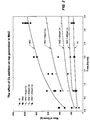
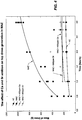
- Figures 2 to 4 are graphs of the mass of dross versus time for the molten alloy baths, with the Figure 2 results focusing on the results for the Ca alloys and the Figure 3 results focusing on the results for the Sr alloys and the Figure 4 results highlighting selected results for Ca and Sr from Figures 2 and 3 .
- Figure 5 is a graph of the mass of dross versus Ca content in molten alloy baths after process times of 1 and 3 hours.
- Figures 2 to 5 clearly show that the level of top dross generated in an Al-Zn-Si-Mg alloy bath can be significantly reduced by additions of Ca or Sr to MAZ alloy coating baths. More particularly, Figures 2 to 5 show that:
- Figures 2 to 5 were further confirmed for Ca in a line trial conducted for approximately 2 weeks.
- the line trial was carried out on the above-mentioned AZ alloy to which Mg and Ca were added at different points in time during the course of the line trial.
- Figure 6 shows the dross collected during the line trial and that the results are consistent with what was observed in the laboratory work. In particular, Figure 6 shows that there was a substantial increase in the amount of dross generated in the molten bath with the addition of Mg to the bath and a substantial decrease in the amount of dross as a consequence of the addition of Ca to the bath.
- the applicant attributes the reduction in the dross level to reduction in the entrainment of molten metal, gas, and intermetallic particles in the oxide film in the molten bath (i.e. in the top dross layer in the bath) that resulted from (a) changes to the apparent surface tension at the liquid metal/oxide interface as a result of the Ca and Sr additions and (b) changes in the nature of the oxide film as a result of the Ca and Sr additions.
- the changes in the nature of the oxide film reduced the level of oxide stringers formed, which in turn assists in an overall reduction in liquid droplet entrainment.
- the changes in the entrainment lead to reductions in the level of top dross generation in molten Al-Zn-Si-Mg alloys.
- Ca and Sr are examples of elements that can be added to a molten bath of an Al-Zn-Si-Mg alloy to reduce the entrainment of molten metal, gas, and intermetallic particles in the oxide film in the bath and thereby reduce the level of dross in the bath.
- Other bath additions include, by way of example, rare earth elements such as yttrium and combinations of rare earths and calcium and strontium and calcium/strontium.
- the Ca and/or Sr may be added to the bath as required. It could be by way of specific additions of Ca and/or Sr compounds on a continuous or a periodic basis. It could also be by way of the inclusion of Ca and/or in A1 and/or Zn ingots that are provided as feed materials for the bath.
Landscapes
- Chemical & Material Sciences (AREA)
- Engineering & Computer Science (AREA)
- Materials Engineering (AREA)
- Mechanical Engineering (AREA)
- Metallurgy (AREA)
- Organic Chemistry (AREA)
- Chemical Kinetics & Catalysis (AREA)
- Coating With Molten Metal (AREA)
Claims (13)
- Verfahren zum Bilden einer Al-Zn-Si-Mg-Legierungsbeschichtung auf einem Band, wobei das Verfahren das Führen eines Stahlbandes über eine Auslaufschnauze eines Wärmebehandlungsofens nach unten in und durch ein Schmelzbad beinhaltet, das eine geschmolzene Al-Zn-Si-Mg-Legierungsschicht und eine Oberschlackeschicht auf der geschmolzenen Legierungsschicht beinhaltet, wobei die geschmolzene Legierung eine Beschichtung aus der geschmolzenen Legierung auf dem Band bildet, und Entnehmen des beschichteten Bandes aus dem Bad durch Führen des beschichteten Bandes nach oben durch die Oberschlackeschicht außerhalb der Auslaufschnauze, wobei die Legierung die folgenden Bereiche der Elemente AI, Zn, Si und Mg in Gew.-% aufweist: AI: 45 bis 60 %; Zn: 35 bis 50 %; Si: 1,2 bis 2,5 % und Mg: 1,0 bis 3,0 %; und wobei das Verfahren ferner das Steuern der Bedingungen im Schmelzbad beinhaltet, um die Oberschlackenschicht im Schmelzbad durch Steuern der Zusammensetzung des Bades zu minimieren, um die Oberschlackenschicht im Schmelzbad durch Steuern der Zusammensetzung des Bades, um (a) Ca in einer Menge, die höher ist als 50 ppm Ca und geringer als 1000 ppm Ca, und (b) Sr im Bad zu beinhalten, zu minimieren.
- Verfahren nach Anspruch 1, beinhaltend das Steuern der Zusammensetzung des Bades, um mehr als 150 ppm Ca zu beinhalten.
- Verfahren nach einem der vorhergehenden Ansprüche, beinhaltend das Steuern der Zusammensetzung des Bades, um weniger als 750 ppm Ca zu beinhalten.
- Verfahren nach Anspruch 3, beinhaltend das Steuern der Zusammensetzung des Bades, um weniger als 500 ppm Ca zu beinhalten.
- Verfahren nach einem der vorhergehenden Ansprüche, beinhaltend das Steuern der Zusammensetzung des Bades, um mehr als 100 ppm Sr zu beinhalten.
- Verfahren nach Anspruch 5, beinhaltend das Steuern der Zusammensetzung des Bades, um mehr als 150 ppm Sr zu beinhalten.
- Verfahren nach Anspruch 6, beinhaltend das Steuern der Zusammensetzung des Bades, um mehr als 200 ppm Sr zu beinhalten.
- Verfahren nach einem der vorhergehenden Ansprüche, beinhaltend das Steuern der Zusammensetzung des Bades, um weniger als 1250 ppm Sr zu beinhalten.
- Verfahren nach Anspruch 8, beinhaltend das Steuern der Zusammensetzung des Bades, um weniger als 1000 ppm Sr zu beinhalten.
- Verfahren nach einem der vorhergehenden Ansprüche, beinhaltend das Steuern der Zusammensetzung des Bades, um die Oberschlackeschicht in dem Schmelzbad durch Einschließen von Seltenerdelementen wie Yttrium und Kombinationen von seltenen Erden in der Zusammensetzung des Bades zu minimieren.
- Verfahren nach einem der vorhergehenden Ansprüche, wobei die Al-Zn-Si-Mg-Legierung mehr als 1,0 Gew.-% Mg umfasst.
- Verfahren nach einem der vorhergehenden Ansprüche, wobei die Al-Zn-Si-Mg-Legierung weniger als 3 Gew.-% Mg umfasst.
- Verfahren nach einem der vorhergehenden Ansprüche, wobei die Al-Zn-Si-Mg-Legierung mehr als 1,2 Gew.-% Si umfasst.
Applications Claiming Priority (3)
| Application Number | Priority Date | Filing Date | Title |
|---|---|---|---|
| AU2010900287A AU2010900287A0 (en) | 2010-01-25 | Metal-coated steel strip | |
| EP11734260.0A EP2529039B1 (de) | 2010-01-25 | 2011-01-25 | Metallbeschichteter stahlstreifen |
| PCT/AU2011/000069 WO2011088518A1 (en) | 2010-01-25 | 2011-01-25 | Metal-coated steel strip |
Related Parent Applications (2)
| Application Number | Title | Priority Date | Filing Date |
|---|---|---|---|
| EP11734260.0A Division-Into EP2529039B1 (de) | 2010-01-25 | 2011-01-25 | Metallbeschichteter stahlstreifen |
| EP11734260.0A Division EP2529039B1 (de) | 2010-01-25 | 2011-01-25 | Metallbeschichteter stahlstreifen |
Publications (2)
| Publication Number | Publication Date |
|---|---|
| EP3486349A1 EP3486349A1 (de) | 2019-05-22 |
| EP3486349B1 true EP3486349B1 (de) | 2020-07-01 |
Family
ID=44306309
Family Applications (2)
| Application Number | Title | Priority Date | Filing Date |
|---|---|---|---|
| EP11734260.0A Active EP2529039B1 (de) | 2010-01-25 | 2011-01-25 | Metallbeschichteter stahlstreifen |
| EP18212939.5A Active EP3486349B1 (de) | 2010-01-25 | 2011-01-25 | Metallbeschichteter stahlstreifen |
Family Applications Before (1)
| Application Number | Title | Priority Date | Filing Date |
|---|---|---|---|
| EP11734260.0A Active EP2529039B1 (de) | 2010-01-25 | 2011-01-25 | Metallbeschichteter stahlstreifen |
Country Status (11)
| Country | Link |
|---|---|
| US (3) | US20130059086A1 (de) |
| EP (2) | EP2529039B1 (de) |
| JP (5) | JP6342117B2 (de) |
| KR (7) | KR20210019582A (de) |
| CN (1) | CN102844457B (de) |
| AU (6) | AU2011207118B2 (de) |
| ES (2) | ES2817873T3 (de) |
| MY (1) | MY173287A (de) |
| NZ (1) | NZ601379A (de) |
| TW (1) | TWI529259B (de) |
| WO (1) | WO2011088518A1 (de) |
Families Citing this family (9)
| Publication number | Priority date | Publication date | Assignee | Title |
|---|---|---|---|---|
| KR20210019582A (ko) * | 2010-01-25 | 2021-02-22 | 블루스코프 스틸 리미티드 | 금속-코팅된 강철 스트립 |
| CN102312130B (zh) * | 2011-09-07 | 2013-04-24 | 东北大学 | 一种五元合金热浸镀层原料制备和使用方法 |
| AU2012325673B2 (en) * | 2011-10-18 | 2017-07-06 | Bluescope Steel Limited | Metal-coated steel strip |
| RU2485205C1 (ru) * | 2011-11-23 | 2013-06-20 | Российская Федерация, от имени которой выступает Министерство промышленности и торговли Российской Федерации (Минпромторг России) | Состав расплава на основе цинка для нанесения защитных покрытий на стальную полосу горячим погружением |
| CN102682920B (zh) * | 2012-05-14 | 2014-04-23 | 广西平果博导铝镁线缆有限公司 | 一种铝镁合金线材的生产方法 |
| JP5991379B2 (ja) | 2013-03-25 | 2016-09-14 | Jfeスチール株式会社 | Al−Zn系めっき鋼板 |
| JP6409038B2 (ja) | 2016-09-30 | 2018-10-17 | 株式会社Subaru | 車両の乗員保護装置 |
| CN108018513A (zh) * | 2016-10-28 | 2018-05-11 | 宝山钢铁股份有限公司 | 一种热浸镀锌铝镁镀层钢板及其制造方法 |
| CN118326302A (zh) * | 2023-01-10 | 2024-07-12 | 宝山钢铁股份有限公司 | 一种锌铝镁镀层钢板及其制造方法 |
Family Cites Families (29)
| Publication number | Priority date | Publication date | Assignee | Title |
|---|---|---|---|---|
| AU544400B2 (en) * | 1980-03-25 | 1985-05-23 | International Lead Zinc Research Organization Inc. | Zinc-aluminum alloys and coatings |
| JPH04272163A (ja) * | 1991-02-27 | 1992-09-28 | Nippon Steel Corp | 溶融亜鉛めっき鋼板の合金化制御方法 |
| JPH10158798A (ja) * | 1996-11-29 | 1998-06-16 | Nippon Carbon Co Ltd | メッキ浴上ドロスの処理方法ならびにその装置 |
| DE69916485D1 (de) * | 1998-10-05 | 2004-05-19 | Internat Zinc Co | Vorrichtung und verfahren zur entfernung von krätze mit erhöhter zinkausbeute aus einem zinkschmelze enthaltenden gefäss |
| JP3983932B2 (ja) * | 1999-05-19 | 2007-09-26 | 日新製鋼株式会社 | 表面外観の良好な高耐食性Mg含有溶融Zn−Al系合金めっき鋼板 |
| JP4267184B2 (ja) | 1999-06-29 | 2009-05-27 | 新日本製鐵株式会社 | 耐食性、外観に優れた溶融アルミめっき鋼板及びその製造法 |
| JP4136286B2 (ja) | 1999-08-09 | 2008-08-20 | 新日本製鐵株式会社 | 耐食性に優れたZn−Al−Mg−Si合金めっき鋼材およびその製造方法 |
| JP4264167B2 (ja) * | 1999-09-10 | 2009-05-13 | 新日本製鐵株式会社 | 耐食性に優れた溶融めっき鋼板 |
| JP2001316791A (ja) * | 2000-04-28 | 2001-11-16 | Nippon Steel Corp | 耐食性、外観に優れた溶融亜鉛−アルミ系めっき鋼板 |
| JP4696364B2 (ja) * | 2001-01-24 | 2011-06-08 | Jfeスチール株式会社 | 耐食性と表面外観に優れた溶融亜鉛系めっき鋼板 |
| JP2002241916A (ja) * | 2001-02-09 | 2002-08-28 | Nippon Steel Corp | 耐食性、加工性および溶接性に優れためっき鋼板とその製造方法 |
| JP2002241962A (ja) * | 2001-02-13 | 2002-08-28 | Sumitomo Metal Ind Ltd | 溶融Zn−Al−Mg合金めっき鋼板とその製造方法 |
| JP3580258B2 (ja) * | 2001-02-14 | 2004-10-20 | 住友金属工業株式会社 | 意匠性に優れた溶融Al−Zn系合金めっき鋼板とその製造方法 |
| KR20030054469A (ko) * | 2001-12-26 | 2003-07-02 | 주식회사 포스코 | 내식성 및 도금작업성이 우수한 Zn-Al-Mg계합금도금강판 |
| JP3779941B2 (ja) * | 2002-01-09 | 2006-05-31 | 新日本製鐵株式会社 | 塗装後耐食性と塗装鮮映性に優れた亜鉛めっき鋼板 |
| JP3843057B2 (ja) * | 2002-10-23 | 2006-11-08 | 新日本製鐵株式会社 | 外観品位に優れた溶融めっき鋼板および溶融めっき鋼板の製造方法 |
| AU2003901424A0 (en) * | 2003-03-20 | 2003-04-10 | Bhp Steel Limited | A method of controlling surface defects in metal-coated strip |
| JP4461866B2 (ja) * | 2004-03-24 | 2010-05-12 | Jfeスチール株式会社 | 耐食性および曲げ加工性に優れた溶融Zn−Al系合金めっき鋼板およびその製造方法 |
| JP5020228B2 (ja) * | 2005-04-05 | 2012-09-05 | ブルースコープ・スティール・リミテッド | 金属被覆スチールストリップ |
| JP2007063612A (ja) * | 2005-08-31 | 2007-03-15 | Mitsubishi-Hitachi Metals Machinery Inc | 連続溶融めっき設備 |
| WO2007108496A1 (ja) * | 2006-03-20 | 2007-09-27 | Nippon Steel Corporation | 高耐食性溶融Zn系めっき鋼材 |
| JP4255483B2 (ja) | 2006-06-02 | 2009-04-15 | 田中亜鉛鍍金株式会社 | 二浴法によるZn−Al合金めっきにおける浴管理方法 |
| US20090269611A1 (en) * | 2006-08-29 | 2009-10-29 | Bluescope Steel Limited | Metal-coated steel strip |
| AU2007291957B2 (en) * | 2006-08-30 | 2013-01-17 | Bluescope Steel Limited | Metal-coated steel strip |
| WO2009055843A1 (en) | 2007-10-29 | 2009-05-07 | Bluescope Steel Limited | Metal-coated steel strip |
| EP2250296B1 (de) * | 2008-03-13 | 2020-10-14 | Bluescope Steel Limited | Metallbeschichtetes stahlband und methode zu seiner herstellung |
| JP5130486B2 (ja) | 2008-04-14 | 2013-01-30 | 新日鐵住金株式会社 | 高耐食性溶融Zn系めっき鋼材 |
| CN101457320A (zh) | 2009-01-04 | 2009-06-17 | 上海大学 | 钢材热浸镀用Al-Zn-Mg-Si合金 |
| KR20210019582A (ko) * | 2010-01-25 | 2021-02-22 | 블루스코프 스틸 리미티드 | 금속-코팅된 강철 스트립 |
-
2011
- 2011-01-25 KR KR1020217004064A patent/KR20210019582A/ko not_active Ceased
- 2011-01-25 KR KR1020177031917A patent/KR20170125139A/ko not_active Ceased
- 2011-01-25 EP EP11734260.0A patent/EP2529039B1/de active Active
- 2011-01-25 ES ES18212939T patent/ES2817873T3/es active Active
- 2011-01-25 KR KR1020187025422A patent/KR20180100725A/ko not_active Ceased
- 2011-01-25 US US13/575,100 patent/US20130059086A1/en not_active Abandoned
- 2011-01-25 KR KR1020257011246A patent/KR20250051798A/ko active Pending
- 2011-01-25 AU AU2011207118A patent/AU2011207118B2/en active Active
- 2011-01-25 TW TW100102625A patent/TWI529259B/zh active
- 2011-01-25 JP JP2012550266A patent/JP6342117B2/ja active Active
- 2011-01-25 WO PCT/AU2011/000069 patent/WO2011088518A1/en not_active Ceased
- 2011-01-25 KR KR1020227039823A patent/KR20220158850A/ko not_active Ceased
- 2011-01-25 CN CN201180015926.2A patent/CN102844457B/zh active Active
- 2011-01-25 ES ES11734260T patent/ES2728460T3/es active Active
- 2011-01-25 EP EP18212939.5A patent/EP3486349B1/de active Active
- 2011-01-25 MY MYPI2012003360A patent/MY173287A/en unknown
- 2011-01-25 KR KR1020127021931A patent/KR20120123460A/ko not_active Ceased
- 2011-01-25 NZ NZ601379A patent/NZ601379A/en unknown
- 2011-01-25 KR KR1020207002272A patent/KR20200011589A/ko not_active Ceased
-
2016
- 2016-05-26 JP JP2016105462A patent/JP2016194160A/ja active Pending
- 2016-08-17 AU AU2016216619A patent/AU2016216619A1/en not_active Abandoned
-
2018
- 2018-10-19 JP JP2018197596A patent/JP6805218B2/ja active Active
- 2018-11-08 AU AU2018260895A patent/AU2018260895B2/en active Active
-
2020
- 2020-12-03 JP JP2020201153A patent/JP7242625B2/ja active Active
-
2021
- 2021-01-18 AU AU2021200262A patent/AU2021200262A1/en not_active Abandoned
- 2021-06-03 US US17/338,063 patent/US20210292872A1/en not_active Abandoned
-
2022
- 2022-12-09 JP JP2022197258A patent/JP7520946B2/ja active Active
-
2023
- 2023-02-09 AU AU2023200715A patent/AU2023200715B2/en active Active
- 2023-10-18 US US18/489,518 patent/US20240158891A1/en active Pending
-
2025
- 2025-07-15 AU AU2025205455A patent/AU2025205455A1/en active Pending
Non-Patent Citations (1)
| Title |
|---|
| None * |
Also Published As
Similar Documents
| Publication | Publication Date | Title |
|---|---|---|
| AU2023200715B2 (en) | Metal-coated steel strip | |
| JP2023024442A (ja) | 金属被覆鉄ストリップ | |
| US20190368022A1 (en) | Metal-coated steel strip | |
| US10731241B2 (en) | Metal-coated steel strip | |
| KR101656281B1 (ko) | 금속 도금된 스트립에서의 표면결함을 제어하는 방법 | |
| NZ621776B2 (en) | Metal-coated steel strip |
Legal Events
| Date | Code | Title | Description |
|---|---|---|---|
| PUAI | Public reference made under article 153(3) epc to a published international application that has entered the european phase |
Free format text: ORIGINAL CODE: 0009012 |
|
| STAA | Information on the status of an ep patent application or granted ep patent |
Free format text: STATUS: THE APPLICATION HAS BEEN PUBLISHED |
|
| AC | Divisional application: reference to earlier application |
Ref document number: 2529039 Country of ref document: EP Kind code of ref document: P |
|
| AK | Designated contracting states |
Kind code of ref document: A1 Designated state(s): AL AT BE BG CH CY CZ DE DK EE ES FI FR GB GR HR HU IE IS IT LI LT LU LV MC MK MT NL NO PL PT RO RS SE SI SK SM TR |
|
| STAA | Information on the status of an ep patent application or granted ep patent |
Free format text: STATUS: REQUEST FOR EXAMINATION WAS MADE |
|
| STAA | Information on the status of an ep patent application or granted ep patent |
Free format text: STATUS: EXAMINATION IS IN PROGRESS |
|
| 17P | Request for examination filed |
Effective date: 20191122 |
|
| RBV | Designated contracting states (corrected) |
Designated state(s): AL AT BE BG CH CY CZ DE DK EE ES FI FR GB GR HR HU IE IS IT LI LT LU LV MC MK MT NL NO PL PT RO RS SE SI SK SM TR |
|
| 17Q | First examination report despatched |
Effective date: 20191220 |
|
| GRAP | Despatch of communication of intention to grant a patent |
Free format text: ORIGINAL CODE: EPIDOSNIGR1 |
|
| STAA | Information on the status of an ep patent application or granted ep patent |
Free format text: STATUS: GRANT OF PATENT IS INTENDED |
|
| INTG | Intention to grant announced |
Effective date: 20200205 |
|
| GRAS | Grant fee paid |
Free format text: ORIGINAL CODE: EPIDOSNIGR3 |
|
| GRAA | (expected) grant |
Free format text: ORIGINAL CODE: 0009210 |
|
| STAA | Information on the status of an ep patent application or granted ep patent |
Free format text: STATUS: THE PATENT HAS BEEN GRANTED |
|
| AC | Divisional application: reference to earlier application |
Ref document number: 2529039 Country of ref document: EP Kind code of ref document: P |
|
| AK | Designated contracting states |
Kind code of ref document: B1 Designated state(s): AL AT BE BG CH CY CZ DE DK EE ES FI FR GB GR HR HU IE IS IT LI LT LU LV MC MK MT NL NO PL PT RO RS SE SI SK SM TR |
|
| REG | Reference to a national code |
Ref country code: CH Ref legal event code: EP Ref country code: AT Ref legal event code: REF Ref document number: 1286250 Country of ref document: AT Kind code of ref document: T Effective date: 20200715 |
|
| REG | Reference to a national code |
Ref country code: IE Ref legal event code: FG4D |
|
| REG | Reference to a national code |
Ref country code: DE Ref legal event code: R096 Ref document number: 602011067625 Country of ref document: DE |
|
| REG | Reference to a national code |
Ref country code: NL Ref legal event code: FP |
|
| REG | Reference to a national code |
Ref country code: LT Ref legal event code: MG4D |
|
| PG25 | Lapsed in a contracting state [announced via postgrant information from national office to epo] |
Ref country code: BG Free format text: LAPSE BECAUSE OF FAILURE TO SUBMIT A TRANSLATION OF THE DESCRIPTION OR TO PAY THE FEE WITHIN THE PRESCRIBED TIME-LIMIT Effective date: 20201001 |
|
| REG | Reference to a national code |
Ref country code: AT Ref legal event code: MK05 Ref document number: 1286250 Country of ref document: AT Kind code of ref document: T Effective date: 20200701 |
|
| PG25 | Lapsed in a contracting state [announced via postgrant information from national office to epo] |
Ref country code: LT Free format text: LAPSE BECAUSE OF FAILURE TO SUBMIT A TRANSLATION OF THE DESCRIPTION OR TO PAY THE FEE WITHIN THE PRESCRIBED TIME-LIMIT Effective date: 20200701 Ref country code: HR Free format text: LAPSE BECAUSE OF FAILURE TO SUBMIT A TRANSLATION OF THE DESCRIPTION OR TO PAY THE FEE WITHIN THE PRESCRIBED TIME-LIMIT Effective date: 20200701 Ref country code: PT Free format text: LAPSE BECAUSE OF FAILURE TO SUBMIT A TRANSLATION OF THE DESCRIPTION OR TO PAY THE FEE WITHIN THE PRESCRIBED TIME-LIMIT Effective date: 20201102 Ref country code: FI Free format text: LAPSE BECAUSE OF FAILURE TO SUBMIT A TRANSLATION OF THE DESCRIPTION OR TO PAY THE FEE WITHIN THE PRESCRIBED TIME-LIMIT Effective date: 20200701 Ref country code: NO Free format text: LAPSE BECAUSE OF FAILURE TO SUBMIT A TRANSLATION OF THE DESCRIPTION OR TO PAY THE FEE WITHIN THE PRESCRIBED TIME-LIMIT Effective date: 20201001 Ref country code: GR Free format text: LAPSE BECAUSE OF FAILURE TO SUBMIT A TRANSLATION OF THE DESCRIPTION OR TO PAY THE FEE WITHIN THE PRESCRIBED TIME-LIMIT Effective date: 20201002 Ref country code: AT Free format text: LAPSE BECAUSE OF FAILURE TO SUBMIT A TRANSLATION OF THE DESCRIPTION OR TO PAY THE FEE WITHIN THE PRESCRIBED TIME-LIMIT Effective date: 20200701 Ref country code: CZ Free format text: LAPSE BECAUSE OF FAILURE TO SUBMIT A TRANSLATION OF THE DESCRIPTION OR TO PAY THE FEE WITHIN THE PRESCRIBED TIME-LIMIT Effective date: 20200701 Ref country code: SE Free format text: LAPSE BECAUSE OF FAILURE TO SUBMIT A TRANSLATION OF THE DESCRIPTION OR TO PAY THE FEE WITHIN THE PRESCRIBED TIME-LIMIT Effective date: 20200701 |
|
| PG25 | Lapsed in a contracting state [announced via postgrant information from national office to epo] |
Ref country code: RS Free format text: LAPSE BECAUSE OF FAILURE TO SUBMIT A TRANSLATION OF THE DESCRIPTION OR TO PAY THE FEE WITHIN THE PRESCRIBED TIME-LIMIT Effective date: 20200701 Ref country code: PL Free format text: LAPSE BECAUSE OF FAILURE TO SUBMIT A TRANSLATION OF THE DESCRIPTION OR TO PAY THE FEE WITHIN THE PRESCRIBED TIME-LIMIT Effective date: 20200701 Ref country code: LV Free format text: LAPSE BECAUSE OF FAILURE TO SUBMIT A TRANSLATION OF THE DESCRIPTION OR TO PAY THE FEE WITHIN THE PRESCRIBED TIME-LIMIT Effective date: 20200701 Ref country code: IS Free format text: LAPSE BECAUSE OF FAILURE TO SUBMIT A TRANSLATION OF THE DESCRIPTION OR TO PAY THE FEE WITHIN THE PRESCRIBED TIME-LIMIT Effective date: 20201101 |
|
| REG | Reference to a national code |
Ref country code: DE Ref legal event code: R097 Ref document number: 602011067625 Country of ref document: DE |
|
| REG | Reference to a national code |
Ref country code: ES Ref legal event code: FG2A Ref document number: 2817873 Country of ref document: ES Kind code of ref document: T3 Effective date: 20210408 |
|
| PG25 | Lapsed in a contracting state [announced via postgrant information from national office to epo] |
Ref country code: EE Free format text: LAPSE BECAUSE OF FAILURE TO SUBMIT A TRANSLATION OF THE DESCRIPTION OR TO PAY THE FEE WITHIN THE PRESCRIBED TIME-LIMIT Effective date: 20200701 Ref country code: RO Free format text: LAPSE BECAUSE OF FAILURE TO SUBMIT A TRANSLATION OF THE DESCRIPTION OR TO PAY THE FEE WITHIN THE PRESCRIBED TIME-LIMIT Effective date: 20200701 Ref country code: DK Free format text: LAPSE BECAUSE OF FAILURE TO SUBMIT A TRANSLATION OF THE DESCRIPTION OR TO PAY THE FEE WITHIN THE PRESCRIBED TIME-LIMIT Effective date: 20200701 Ref country code: SM Free format text: LAPSE BECAUSE OF FAILURE TO SUBMIT A TRANSLATION OF THE DESCRIPTION OR TO PAY THE FEE WITHIN THE PRESCRIBED TIME-LIMIT Effective date: 20200701 Ref country code: IT Free format text: LAPSE BECAUSE OF FAILURE TO SUBMIT A TRANSLATION OF THE DESCRIPTION OR TO PAY THE FEE WITHIN THE PRESCRIBED TIME-LIMIT Effective date: 20200701 |
|
| PLBE | No opposition filed within time limit |
Free format text: ORIGINAL CODE: 0009261 |
|
| STAA | Information on the status of an ep patent application or granted ep patent |
Free format text: STATUS: NO OPPOSITION FILED WITHIN TIME LIMIT |
|
| PG25 | Lapsed in a contracting state [announced via postgrant information from national office to epo] |
Ref country code: AL Free format text: LAPSE BECAUSE OF FAILURE TO SUBMIT A TRANSLATION OF THE DESCRIPTION OR TO PAY THE FEE WITHIN THE PRESCRIBED TIME-LIMIT Effective date: 20200701 |
|
| 26N | No opposition filed |
Effective date: 20210406 |
|
| PG25 | Lapsed in a contracting state [announced via postgrant information from national office to epo] |
Ref country code: SK Free format text: LAPSE BECAUSE OF FAILURE TO SUBMIT A TRANSLATION OF THE DESCRIPTION OR TO PAY THE FEE WITHIN THE PRESCRIBED TIME-LIMIT Effective date: 20200701 |
|
| PG25 | Lapsed in a contracting state [announced via postgrant information from national office to epo] |
Ref country code: SI Free format text: LAPSE BECAUSE OF FAILURE TO SUBMIT A TRANSLATION OF THE DESCRIPTION OR TO PAY THE FEE WITHIN THE PRESCRIBED TIME-LIMIT Effective date: 20200701 Ref country code: MC Free format text: LAPSE BECAUSE OF FAILURE TO SUBMIT A TRANSLATION OF THE DESCRIPTION OR TO PAY THE FEE WITHIN THE PRESCRIBED TIME-LIMIT Effective date: 20200701 |
|
| REG | Reference to a national code |
Ref country code: CH Ref legal event code: PL |
|
| PG25 | Lapsed in a contracting state [announced via postgrant information from national office to epo] |
Ref country code: LI Free format text: LAPSE BECAUSE OF NON-PAYMENT OF DUE FEES Effective date: 20210131 Ref country code: CH Free format text: LAPSE BECAUSE OF NON-PAYMENT OF DUE FEES Effective date: 20210131 |
|
| PG25 | Lapsed in a contracting state [announced via postgrant information from national office to epo] |
Ref country code: IE Free format text: LAPSE BECAUSE OF NON-PAYMENT OF DUE FEES Effective date: 20210125 |
|
| PG25 | Lapsed in a contracting state [announced via postgrant information from national office to epo] |
Ref country code: CY Free format text: LAPSE BECAUSE OF FAILURE TO SUBMIT A TRANSLATION OF THE DESCRIPTION OR TO PAY THE FEE WITHIN THE PRESCRIBED TIME-LIMIT Effective date: 20200701 |
|
| P01 | Opt-out of the competence of the unified patent court (upc) registered |
Effective date: 20230519 |
|
| PG25 | Lapsed in a contracting state [announced via postgrant information from national office to epo] |
Ref country code: HU Free format text: LAPSE BECAUSE OF FAILURE TO SUBMIT A TRANSLATION OF THE DESCRIPTION OR TO PAY THE FEE WITHIN THE PRESCRIBED TIME-LIMIT; INVALID AB INITIO Effective date: 20110125 |
|
| PG25 | Lapsed in a contracting state [announced via postgrant information from national office to epo] |
Ref country code: MK Free format text: LAPSE BECAUSE OF FAILURE TO SUBMIT A TRANSLATION OF THE DESCRIPTION OR TO PAY THE FEE WITHIN THE PRESCRIBED TIME-LIMIT Effective date: 20200701 |
|
| PG25 | Lapsed in a contracting state [announced via postgrant information from national office to epo] |
Ref country code: MT Free format text: LAPSE BECAUSE OF FAILURE TO SUBMIT A TRANSLATION OF THE DESCRIPTION OR TO PAY THE FEE WITHIN THE PRESCRIBED TIME-LIMIT Effective date: 20200701 |
|
| PG25 | Lapsed in a contracting state [announced via postgrant information from national office to epo] |
Ref country code: TR Free format text: LAPSE BECAUSE OF FAILURE TO SUBMIT A TRANSLATION OF THE DESCRIPTION OR TO PAY THE FEE WITHIN THE PRESCRIBED TIME-LIMIT Effective date: 20200701 |
|
| PGFP | Annual fee paid to national office [announced via postgrant information from national office to epo] |
Ref country code: LU Payment date: 20260121 Year of fee payment: 16 Ref country code: NL Payment date: 20260121 Year of fee payment: 16 |
|
| PGFP | Annual fee paid to national office [announced via postgrant information from national office to epo] |
Ref country code: GB Payment date: 20260123 Year of fee payment: 16 |
|
| PGFP | Annual fee paid to national office [announced via postgrant information from national office to epo] |
Ref country code: ES Payment date: 20260227 Year of fee payment: 16 |
|
| PGFP | Annual fee paid to national office [announced via postgrant information from national office to epo] |
Ref country code: DE Payment date: 20260121 Year of fee payment: 16 |
|
| PGFP | Annual fee paid to national office [announced via postgrant information from national office to epo] |
Ref country code: BE Payment date: 20260121 Year of fee payment: 16 |
|
| PGFP | Annual fee paid to national office [announced via postgrant information from national office to epo] |
Ref country code: FR Payment date: 20260123 Year of fee payment: 16 |