EP3486159B1 - Fin for watercraft - Google Patents
Fin for watercraft Download PDFInfo
- Publication number
- EP3486159B1 EP3486159B1 EP18212428.9A EP18212428A EP3486159B1 EP 3486159 B1 EP3486159 B1 EP 3486159B1 EP 18212428 A EP18212428 A EP 18212428A EP 3486159 B1 EP3486159 B1 EP 3486159B1
- Authority
- EP
- European Patent Office
- Prior art keywords
- fin
- tab
- plug
- cavity
- fin plug
- Prior art date
- Legal status (The legal status is an assumption and is not a legal conclusion. Google has not performed a legal analysis and makes no representation as to the accuracy of the status listed.)
- Active
Links
- XLYOFNOQVPJJNP-UHFFFAOYSA-N water Substances O XLYOFNOQVPJJNP-UHFFFAOYSA-N 0.000 claims description 31
- 238000003780 insertion Methods 0.000 claims description 7
- 230000037431 insertion Effects 0.000 claims description 7
- 230000007704 transition Effects 0.000 claims description 4
- 230000000717 retained effect Effects 0.000 claims description 2
- 239000000463 material Substances 0.000 description 14
- 230000013011 mating Effects 0.000 description 9
- 238000009434 installation Methods 0.000 description 7
- 230000008901 benefit Effects 0.000 description 4
- CNQCVBJFEGMYDW-UHFFFAOYSA-N lawrencium atom Chemical compound [Lr] CNQCVBJFEGMYDW-UHFFFAOYSA-N 0.000 description 4
- 108010036050 human cationic antimicrobial protein 57 Proteins 0.000 description 3
- 239000004743 Polypropylene Substances 0.000 description 2
- 239000004433 Thermoplastic polyurethane Substances 0.000 description 2
- XECAHXYUAAWDEL-UHFFFAOYSA-N acrylonitrile butadiene styrene Chemical compound C=CC=C.C=CC#N.C=CC1=CC=CC=C1 XECAHXYUAAWDEL-UHFFFAOYSA-N 0.000 description 2
- 239000004676 acrylonitrile butadiene styrene Substances 0.000 description 2
- 229920000122 acrylonitrile butadiene styrene Polymers 0.000 description 2
- 230000009471 action Effects 0.000 description 2
- 230000015572 biosynthetic process Effects 0.000 description 2
- 230000002401 inhibitory effect Effects 0.000 description 2
- 230000007246 mechanism Effects 0.000 description 2
- 239000004033 plastic Substances 0.000 description 2
- 229920003023 plastic Polymers 0.000 description 2
- 229920001155 polypropylene Polymers 0.000 description 2
- 229920002379 silicone rubber Polymers 0.000 description 2
- 239000004945 silicone rubber Substances 0.000 description 2
- 229920002725 thermoplastic elastomer Polymers 0.000 description 2
- 229920002803 thermoplastic polyurethane Polymers 0.000 description 2
- RTAQQCXQSZGOHL-UHFFFAOYSA-N Titanium Chemical compound [Ti] RTAQQCXQSZGOHL-UHFFFAOYSA-N 0.000 description 1
- 239000004957 Zytel Substances 0.000 description 1
- 229920006102 Zytel® Polymers 0.000 description 1
- 238000005260 corrosion Methods 0.000 description 1
- 230000007797 corrosion Effects 0.000 description 1
- 230000000881 depressing effect Effects 0.000 description 1
- 230000000694 effects Effects 0.000 description 1
- 239000013013 elastic material Substances 0.000 description 1
- 229920001971 elastomer Polymers 0.000 description 1
- 210000004905 finger nail Anatomy 0.000 description 1
- 238000002347 injection Methods 0.000 description 1
- 239000007924 injection Substances 0.000 description 1
- JEIPFZHSYJVQDO-UHFFFAOYSA-N iron(III) oxide Inorganic materials O=[Fe]O[Fe]=O JEIPFZHSYJVQDO-UHFFFAOYSA-N 0.000 description 1
- 238000004519 manufacturing process Methods 0.000 description 1
- -1 polypropylene Polymers 0.000 description 1
- 230000002829 reductive effect Effects 0.000 description 1
- 238000002407 reforming Methods 0.000 description 1
- 239000011347 resin Substances 0.000 description 1
- 229920005989 resin Polymers 0.000 description 1
- 239000004576 sand Substances 0.000 description 1
- 229910001220 stainless steel Inorganic materials 0.000 description 1
- 239000010935 stainless steel Substances 0.000 description 1
- 230000003068 static effect Effects 0.000 description 1
- 229910052719 titanium Inorganic materials 0.000 description 1
- 239000010936 titanium Substances 0.000 description 1
- 239000011800 void material Substances 0.000 description 1
Images


Classifications
-
- B—PERFORMING OPERATIONS; TRANSPORTING
- B63—SHIPS OR OTHER WATERBORNE VESSELS; RELATED EQUIPMENT
- B63B—SHIPS OR OTHER WATERBORNE VESSELS; EQUIPMENT FOR SHIPPING
- B63B32/00—Water sports boards; Accessories therefor
- B63B32/60—Board appendages, e.g. fins, hydrofoils or centre boards
- B63B32/66—Arrangements for fixation to the board, e.g. fin boxes or foil boxes
-
- B—PERFORMING OPERATIONS; TRANSPORTING
- B63—SHIPS OR OTHER WATERBORNE VESSELS; RELATED EQUIPMENT
- B63B—SHIPS OR OTHER WATERBORNE VESSELS; EQUIPMENT FOR SHIPPING
- B63B32/00—Water sports boards; Accessories therefor
- B63B32/60—Board appendages, e.g. fins, hydrofoils or centre boards
- B63B32/64—Adjustable, e.g. by adding sections, by removing sections or by changing orientation or profile
Description
- The present invention relates to fins which are adapted to be removably attached to a fin plug for installation in a water craft, such as a surfboard or the like.
- A fin plug assembly, and watercraft attachment device, are also described herein for illustrative purposes.
- A water craft, such as a surfboard, particularly one on which a person stands, kneels or sits, when traversing water or riding a wave, generally has at least one fin in an underside of the water craft, generally near the tail end of the water craft. Such fins have a number of functions, including: enabling the craft to travel in a desired direction; facilitating the turning of the craft; preventing the craft from slipping sideways; and providing greater control over the movement of the craft, such as when riding a wave.
- The following discussion is directed mainly to surfboards but it is to be understood that the discussion applies equally to other water craft (and surf craft) which are adapted to include fins, such as sail boards, paddle boards, rescue boards, surf skis, kayaks, and the like.
- Some surfboards have fins integrally formed in the underside of the surfboard and, historically, most surfboards included such integrally formed fins. These integrally formed fins are generally 'glassed in', meaning that they are formed as part of the surfboard by means of fiber-reinforced resin. The formation of such 'glassed in' fins is quite labour intensive and it makes the subsequent sanding and finishing of the board more difficult.
- In the last twenty years or so, it has become more common for surfboards to incorporate fin systems which include removable fins. Such fin systems have numerous benefits, including: enabling the fins to be removed whilst travelling; allowing damaged fins to be easily replaced; and enabling fins of different shapes or styles to be selectively used. These fin systems typically include at least one fin plug embedded in the underside of the surfboard, adapted to receive at least one surfboard fin. Each such fin plug will generally include an open cavity adapted to receive a base portion (or base element) of a surfboard fin. The fin is then able to be removably attached to the surfboard by inserting the relevant base portion (or base element) of the fin into the cavity (or cavities) of the fin plug (or fin plugs). There are numerous known fin systems which incorporate such an arrangement.
- One known and commonly used fin system is described in
US5,464,369 in the name of Fin Control Systems Pty Ltd. This system includes fins, each having two projecting base elements (or tabs) and, for each fin, two fin plugs installed in the underside of the surfboard. Each of the fin plugs has a cavity for receiving one of the base elements. Each fin plug also includes a grub screw for securing the base element within the cavity of the fin plug. - The above fin system of
US5,464,369 has become exceedingly popular and widely used as the system enables fins to be affixed to a surfboard in a highly secure manner whilst also enabling the fins to be easily removed from the surfboard when desired. However, one drawback of the abovementioned system is that the installation and removal of fins from the fin plugs is somewhat time-consuming and requires the use of a tool (e.g. an Allen key) as the grub screws need to be threaded into or out of each cavity in order to secure or release the base elements of each fin (as desired). - Another fin plug which functions in a similar way to that described above is the fin plug assembly described in
PCT/AU/2008/001132 PCT/AU/2008/001132 - Other known fin systems include systems which incorporate a single fin plug, with a single cavity, for each surfboard fin. Typically, such a fin system has quite a large fin plug with an elongated fin cavity for receiving the base element(s) of a fin. In such fin systems it is again usual for each fin to be secured to the surfboard (that is, the base element of the fin to be secured within the cavity of the fin plug) by means of a grub screw arrangement, such as that mentioned above.
-
US 2010/0120305 A1 discloses an auto-fastening skeg system comprising a skeg receiver and a skeg. The skeg has a male component that cooperates with a cavity of the skeg receiver. The cavity has front and rear ends, a spring disposed at said front end and at least one dowel disposed between the front and rear ends. The male component includes a front tip and at least one locking wedge, said locking wedge corresponds in number to the number of dowels. When the male component is set in the cavity and the locking wedge is aligned with the dowel of the receiver, the spring pushes the front tip of the male component against the rear wall of the cavity of the receiver and the locking wedge against the dowel providing a locking mechanism that holds the skeg to the receiver. - There is a present need for fin for a surfboard fin plug adapted to enable surfboard fins to be removably secured to the underside of a surfboard in a quick, easy and secure manner and preferably without the need for using a tool.
- The present invention is directed towards ameliorating at least some of the above described problems associated with prior art fin plugs. More particularly, the present invention is directed towards fins for a fin plug adapted to receive a surfboard fin which enables the fin to be easily and quickly secured to or removed from a surfboard. Even more particularly, the present invention is directed towards surfboard fins for a fin plug, adapted to receive the surfboard fin, which enables the fin to be easily and quickly secured to or removed from a surfboard without the use of a tool.
- In this specification, where a document, act or item of knowledge is referred to or discussed, this reference or discussion is not an admission that the document, act or item of knowledge or any combination thereof was at the priority date:
- a) part of the common general knowledge; or
- b) known to be relevant to an attempt to solve any problem with which this specification is concerned.
- Any reference herein to known prior art does not, unless the contrary indication appears, constitute an admission that such prior art is commonly known by those skilled in the art to which the invention relates, at the priority date of this application.
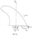
- According to a first aspect of the present invention, there is provided a water craft fin to be removably secured to a water craft fin plug having distinct front and rear open cavities and a bridge section therebetween,
- the front open cavity of the fin plug having a front cavity fin engagement means comprising a protrusion in a front end of the front open cavity and a first recess between the protrusion and a base surface of the front open cavity; and the rear open cavity of the fin plug having a resiliently protruding ring-shaped member extending into the rear open cavity from an elongate side surface of the rear open cavity;
- the water craft fin comprising:
- a base portion having a front tab and a rear tab adapted to be received in the front open cavity and the rear open cavity respectively;
- the front tab includes a nose section at a front portion of the tab which is adapted to engage with the first recess and the protrusion so as to be retained by the front cavity fin engagement means; and
- the rear tab includes a side surface which is partially recessed at a forward location of the rear tab side surface , adapted to at least partially receive the resiliently protruding ring-shaped member of the rear cavity;
- whereby at fin insertion the front tab engages with the front cavity fin engagement means and the fin pivots to insert the rear tab into the rear cavity and engage with the resiliently protruding ring-shaped member such that the fin is removably secured to the fin plug by the fin engagement means and the resiliently protruding ring-shaped member.
- Preferably, the rear tab includes a lower tab portion and a lowermost surface, wherein the lower tab portion is between the partially recessed side surface and the lowermost surface; and wherein the rear tab has a cross-sectional thickness that is relatively thick towards a top of the lower tab portion and relatively thin towards a bottom of the lower tab portion.
- Preferably, the rear tab includes a transition surface between the recessed side surface and a lowermost surface of the rear tab; wherein, when the fin is inserted into the fin plug, the transition surface engages with the resiliently protruding ring member before the recessed side surface engages with the resiliently protruding ring member.
- Preferably, the partially recessed side surface includes a grooved portion; and wherein the grooved portion is adapted to at least partially receive the ring shaped member when the rear tab is in the fin plug.
- Preferably, the partially recessed side surface of the rear tab includes an inclined surface section, the inclined surface section being adapted to cooperate with the ring-shaped member mounted to a resilient rod of the fin plug, so as to cause a force, that is inwardly and laterally into the fin plug, to be applied to the rear tab when the resilient rod bends resiliently; and wherein the force being applied is such that a removal of the rear tab from the fin plug is inhibited.
- More preferably, the inclined surface section is located on the side surface of the rear tab to abut the ring-shaped member of the fin plug when the fin base portion is in the fin plug.
- Preferably, the partially recessed side surface is located on the rear tab to abut the ring-shaped member of the fin plug when the rear tab is in the fin plug.
- Preferably, in use the partially recessed side surface cause: to bend a resilient rod mounting the ring-shaped member of the fin plug, and at least one of the ring-shaped member and the resilient rod of the fin plug to rotate about a longitudinal axis of the resilient rod, when the fin rear tab removably engages with the fin plug.
- Preferably, the nose section of the front tab includes a second recess which receives the protrusion of the front cavity fin engagement means, to facilitate said engagement with the front cavity fin engagement means and pivoting of the fin to insert the rear tab into the rear cavity.
- More preferably, a portion of the nose section of the front tab is adapted to underlie the front cavity protrusion of the fin plug to inhibit movement of the fin when the front tab and the rear tab of the fin are received within the fin plug.
- Preferably, the fin includes a surface between the front tab and the rear tab which is adapted to abut the bridge section of the fin plug.
- Preferably, the water craft is at least one of a surfboard, a surf craft, a sail board, a stand-up paddle board, a rescue board, a surf ski and a kayak.
- It will be appreciated that the features described herein can be provided in the device described herein either independently or in different combinations.
- A detailed description of a preferred embodiment of a surfboard fin according to the first aspect of this invention is given hereinafter, with description of a device/fin plug and watercraft attachment device for illustrative purposes, while referring to the following figures:
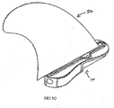
-
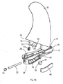
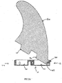
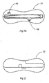
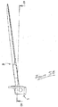
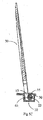
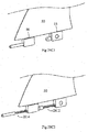
Figures 1A and1B are perspective (exploded) views of an example fin and fin plug assembly.Figure 1B shows the tangent edges with dashed lines. -
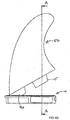
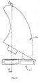
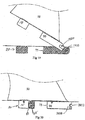
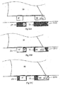
Figure 2A is a side cross-sectional view of an example centre fin and fin plug assembly; -
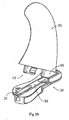
Figure 2B is a perspective view of the fin and fin plug assembly ofFigure 2A ; -
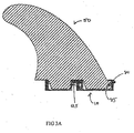
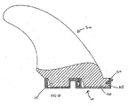
Figure 2C is a cross-sectional front view of the fin and fin plug assembly ofFigure 2A ; -
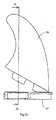
Figure 2D is a side view of the fin and fin plug assembly ofFigure 2A ; -
Figure 2E is front view of the fin and fin plug assembly ofFigure 2A ; -
Figure 2F is a back view of the fin and fin plug assembly ofFigure 2A ; -
Figure 2G is an underneath perspective view of the fin and fin plug assembly ofFigure 2A ; -
Figure 2H is a top view of the fin and fin plug assembly ofFigure 2A ; -
Figure 2I is a bottom view of the fin and fin plug assembly ofFigure 2A ; -
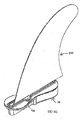
Figure 3A is a side cross-sectional view of the fin and fin plug assembly ofFigure 2A , when the fin has been inserted into the device; -
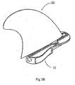
Figure 3B is a top perspective view of the fin and fin plug assembly ofFigure 3A ; -
Figure 3C is a front cross-sectional view of the fin and fin plug assembly ofFigure 3A ; -
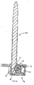
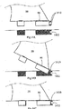
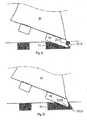
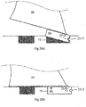
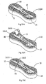
Figure 4A is a side cross-sectional view of an example right-side the fin and fin plug assembly; -
Figure 4B is a back view of the fin and fin plug assembly ofFigure 4A ; -
Figure 4C is a cross-sectional front view of the fin and fin plug assembly ofFigure 4B along the line C-C; -
Figure 4D is a side view of the fin and fin plug assembly ofFigure 4A ; -
Figure 4E is a bottom perspective view of the fin and fin plug assembly offigure 4A ; -
Figure 4F is a cross-sectional side view of the fin and fin plug assembly of theFigure 4A , the fin being received by the device; -
Figure 4G is a top perspective view of the fin and fin plug assembly ofFigure 4F ; -
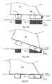
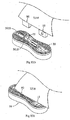
Figure 5A is a side cross-sectional view of an example left-side of the fin and fin plug assembly; -
Figure 5B is a back view of the fin and fin plug assembly ofFigure 5A ; -
Figure 5C is a cross-sectional front view of the fin and fin plug assembly ofFigure 5C ; -
Figure 5D is a side view of the fin and fin plug assembly ofFigure 5A ; -
Figure 5E is a bottom perspective view of the fin and fin plug assembly offigure 5A ; -
Figure 5F is a cross-sectional side view of the fin and fin plug assembly of theFigure 5A , the fin being received by the device; -
Figure 5G is a top perspective view of the fin and fin plug assembly ofFigure 5F ; -
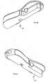
Figure 6A is a top perspective view of an example device or fin plug; -
Figure 6B is another top perspective view of the device or fin plug ofFigure 6A ; -
Figure 6C is an underneath perspective view of the device or fin plug ofFigure 6A ; -
Figure 6D is another underneath perspective view of the device or fin plug ofFigure 6A ; -
Figure 6E is a top elevational view of the device or fin plug ofFigure 6A ; -
Figure 6F is an underneath elevational view of the device or fin plug ofFigure 6A ; -
Figure 6G is a side elevational view of the device or fin plug ofFigure 6A ; -
Figure 6H is another side elevational view of the device or fin plug ofFigure 6A ; -
Figure 6I is a back end elevational view of the device or fin plug ofFigure 6A ; -
Figure 6J is a front end elevational view of the device or fin plug ofFigure 6A ; -
Figure 6K is a cross-sectional view of the device or fin plug ofFigure 6H along the section line A-A; -
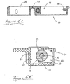
Figure 6L is a cross-sectional view of the device or fin plug ofFigure 6I along the section line B-B; -
Figure 6M is a cross-sectional view of the device or fin plug ofFigure 6J along the section line C-C; -
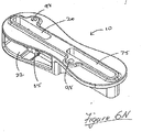
Figure 6N is a top perspective view of the device or fin plug ofFigure 6A , without acap 60 to the lateral cavity; -
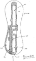
Figure 6O is an exploded view of the device or fin plug ofFigure 6A ; -
Figure 6P is another exploded view of the device or fin plug ofFigure 6A ; -
Figure 7A is a top perspective view of an example right-side device or fin plug; -
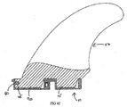
Figure 7B is front cross-sectional view of the device or fin plug ofFigure 7A ; -
Figure 7C is a top cross-sectional view of the device or fin plug ofFigure 7A ; -
Figure 7D is a side cross-sectional view of the device or fin plug ofFigure 7A ; -
Figure 8A is a top perspective view of an example left-side device or fin plug; -
Figure 8B is front cross-sectional view of the device or fin plug ofFigure 8A ; -
Figure 8C is a top cross-sectional view of the device or fin plug ofFigure 8A ; -
Figure 8D is a side cross-sectional view of the device or fin plug ofFigure 8A ; -
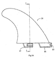
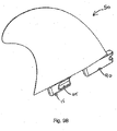
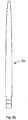
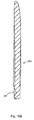
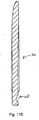
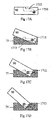
Figure 9A is a side view of an example fin, which can be used with a device or fin plug described herein; -
Figure 9B is a top perspective view of the fin ofFigure 9A ; -
Figure 9C is a bottom perspective view of the fin ofFigure 9A ; -
Figure 9D is a front view of the fin ofFigure 9A ; -
Figure 9E is a back view of the fin ofFigure 9A ; -
Figure 9F is a cross-sectional view of the fin ofFigure 9A ; -
Figure 9G is a top view of the fin ofFigure 9A ; -
Figure 9H is a bottom view of the fin ofFigure 9A ; -
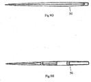
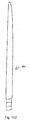
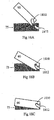
Figure 10A is a side view of an example right-side fin, which can be used with a device or fin plug described herein; -
Figure 10B is a cross-sectional view of the fin ofFigure 10A ; -
Figure 10C is a back view of the fin ofFigure 10A ; -
Figure 10D is a top perspective view of the fin ofFigure 10A ; -
Figure 11A is a side view of an example left-side fin, which can be used with a device or fin plug described herein; -
Figure 11B is a cross-sectional view of the fin ofFigure 11A ; -
Figure 11C is a back view of the fin ofFigure 11A ; -
Figure 11D is a top perspective view of the fin ofFigure 11A ; -
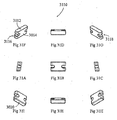
Figures 12A to 27B are example fixing/engagement means to fix a second fin portion within a second cavity of the device/fin plug discussed herein; and, -
Figures 28A to 28C are example adaptors for use with the device/fin plug discussed herein. -
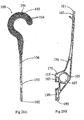
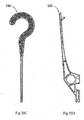
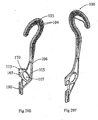
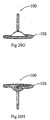
Figures 29A to 29H are respective views of the rear (29A), left side (29B), front (29C), right side (29D), isometric front (29E), isometric rear (29F), top (29G) and bottom (29H) of a water craft attachment device having a hook element, for illustrative purposes only. -
Figures 30A to 31I are views (including elevational views of rear, side, front, top, bottom and corresponding perspective illustrations) of compatibility infills for the fin plug ofFigure 1A , for illustrative purposes only. -
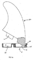
Figures 32A to 32E are a schematic representation of the installation of the compatibility infill ofFigures 30A to 30I into the fin plug. -
Figures 33A to 34I are views (including elevational views of rear, side, front, top, bottom and corresponding perspective illustrations) of full plug infills for the fin plug ofFigure 1A . -
Figures 35A to 32C are a schematic representation of the installation of the full plug infill ofFigures 33A to 34I into the fin plug. - An example of a device or
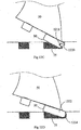
fin plug 10 is shown inFigures 1A and1B . - In this particular example, the
device 10 is used for holding afirst fin portion 15 in a water craft, such as a surfboard or the like (not shown). Thedevice 10 can be formed such that it is integral or insertable into the water craft. - As shown in
Figures 1A and1B , thedevice 10 can include afirst cavity 20, having a cavity wall 25 (and further described below). Thedevice 10 also includes a resilientelongate member 30, which can be located at least partially along an elongate side of thecavity wall 25.Figure 1 also shows that the resilientelongate member 30 can have an extendingportion 35, where the extendingportion 35 extends from theresilient member 30 through arecess 40 or aperture in the elongate side of thecavity wall 25, - Accordingly, when the
first fin portion 15 is inserted into thefirst cavity 20, any one or a combination of the resilientelongate member 30 and the extendingportion 35 can apply a force to thefirst fin portion 15 to hold thefirst fin portion 15 within thefirst cavity 20. - Thus, in one particular example, the resilient
elongate member 30 is a resilient rod or pin, and the extendingportion 35 can includes abulbous portion 45, where thebulbous portion 45 is configured to engage with thefirst fin portion 15. In yet a further example, thebulbous portion 45 can be a part of a wheel-like member formed around theelongate rod 30, where the wheel-like member 35 is configured to move around therod 30 when engaging with thefirst fin portion 15, to hold thefirst fin portion 15 in thefirst cavity 20. -
Figures 1A and1B , for example, show that therod 30 is a pin, or the like, which can act as a spring to allow the wheel-like member 35, to act as a barrel, which can hold thefin 50 in place. Thus thedevice 10 can be in the form of a box which can hold the fin and hold the pin in place.Figure 1 also shows that once therod 30 is inserted into thedevice 10, the insertion can be sealed by aend plug 55, or the like. Theplug 55 can prevent therod 30 moving out of thedevice 10. - Additionally,
Figures 1A and1B also show that thedevice 10 can include one ormore caps portion 35 into thedevice 10. In one particular example, theend cap 55 is typically water tight and can hold both therod 30 and the extendingportion 35 therein. Theside cap 57 can be optional, therod 30 and the extendingportion 35 can be installed without the use of an aperture thatside cap 57 seals. - According to yet a further example, the
first fin portion 15 can also include agrooved portion 65 on aside fin surface 70. The groovedportion 65 is typically configured to engage with the extendingportion 35. Thus, in one example, a surface of the wheel-like member 35, which is typically a curved surface, is configured to site within the groovedportion 65. - It will be appreciated that although the grooved
portion 65 can be formed or shaped such that it substantially conforms or mates with the curved surface of the extendingportion 35, strict conformance or mating is not necessary. In these examples, the groovedportion 65 is configured to roll over the extendingportion 35 and the extendingportion 35 can then lock thefirst fin portion 15 into thefirst cavity 20. It will also be appreciated that when the locking action occurs and thefirst fin portion 15 is pushed into the cavity, therod 30 may bend and may remain slightly bent when applying the force to the extendingportion 35, which subsequently applies a force to the groovedportion 65, in order to maintain thefirst fin portion 15 within thefirst cavity 20. In one particular example, either a lateral or a downward force, or a combination thereof can be applied to maintain thefirst fin portion 15 within thedevice 10. - According to one particular example, when inserting the
fin 50 into thedevice 10, asecond fin portion 90 is inserted initially, where therecess 85 on thesecond fin portion 90 engages with theprotrusion 80 on the device 10 (within the second cavity 75). Once thesecond fin portion 90 is in place, thefirst fin portion 15 is locked into thefirst cavity 20 by pushing down on thefin 50 such that thegroove 65 engages with the extendingportion 35, which is at least partially within thefirst cavity 20. - Thus, in a further example, referring to
Figures 1A and1B , there is provided herein afin plug 10 for installation in a water craft (not shown), saidfin plug 10 including a firstopen cavity 20 adapted to receive abase portion 18 of awater craft fin 50; and, aresilient biasing rod 30 and a protruding member (otherwise referred to herein as an extending portion) 35 cooperating with the biasingrod 30. The protrudingmember 35 is adapted / configured to abut thebase portion 18 of saidfin 50 when received in said firstopen cavity 20. Accordingly, the biasingrod 30 and protrudingmember 35 are adapted to apply a force to thebase portion 18 of saidfin 50 to inhibit removal of saidfin 50 from said firstopen cavity 20. - As shown in
Figures 1A and1B , the biasingrod 30, when inserted into thefin plug 10 is located adjacent the firstopen cavity 20. According to one particular example, the biasingrod 30 extends substantially parallel to aside surface 16 of thebase portion 18 of thefin 50. Thus, the protrudingmember 35 can abut theside surface 16. - It will further be appreciated that the
fin plug 10 can also include alateral cavity 22 where the biasingrod 30 is located within thelateral cavity 22. Thus, thelateral cavity 22 and the firstopen cavity 20 are separated by an apertured wall (herein referred to as the cavity wall) and at a portion of the protrudingmember 35 protrudes through an aperture (or recess) 40 in thewall 25 into the firstopen cavity 20. - The
side surface 16 can include an inclined surface section (otherwise described herein as a grooved portion) 65. Theinclined surface section 65 is adapted to cooperate with the protrudingmember 35 so as to cause a force, inwardly into the firstopen cavity 20 to be applied to thebase portion 18 under the influence of the biasingrod 30. - According to one particular example, the
fin plug 10 can have aforward region 12 and arearward region 14. The protrudingmember 35 is typically located in therearward region 14. - The fin plug 10 can include an additional fin removal inhibiting means located in the
forward region 12. The fin removal inhibiting means can include a fin engagement means which includes a ledge portion (referred to herein as the protrusion) 80 which is adapted to overlie a fin section (referred to herein as the recess) 85 and to inhibit movement of thefin 50 when thebase portion 18 is received within the firstopen cavity 20. - As described herein, the
fin plug 10 can include a secondopen cavity 75. Accordingly, the firstopen cavity 20 can receive a first tab of thebase portion 18 of thefin 50 and the secondopen cavity 75 can receive a second tab of thebase portion 18 of thefin 50. In this particular example, the firstopen cavity 20 is located in therearward region 14 and the second open cavity is located in theforward region 12. And further, theinclined surface section 65 of the base portion of said fin is located on the first tab. Additionally, theledge portion 80 can be located within said second open cavity, and the fin section can be located on the second tab of the base portion of thefin 50. - As shown in
Figures 12A to 12H , the ledge portion can include a ledge extending from one end of said second open cavity and defining a recess between said ledge and a base surface of said second open cavity, said recess being adapted to receive the fin section. - As discussed herein, the extending portion/protruding
member 35 can be wheel-like or a ring-shaped member located about the biasingrod 30. In one particular example, the ring-shaped member can rotate about said biasing rod. In yet a further example, the ring-shaped member does not necessarily have to be cylindrical in shape and may have a circumferential outer surface extending between two side surfaces, where the circumferential outer surface has a convex profile between said side surfaces. - In yet a further example, as particularly shown in
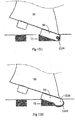
Figures 2A ,3A ,4A ,4F ,5A , and5F , thedevice 10 can also include asecond cavity 75. Thesecond cavity 75 can include aprotrusion 80, where theprotrusion 80 is configured to be inserted into and mate with arespective recess 85 of asecond fin portion 90, to thereby hold thesecond fin portion 90 within thesecond cavity 75. - Thus, for example, any one or a combination of the
protrusion 80 and therecess 85; and, the extendingportion 35 and thefirst fin portion 15 can snap-lock together, and thefin 50 can be held robustly within thedevice 10. - Notably, it will be appreciated by persons skilled in the art that the
second fin portion 90 can be held within thesecond cavity 75 by a number of different mechanical elements/fixing means. Further examples of fixing means for fixing/holding thesecond fin portion 90 into asecond cavity 75 are described below. - In the examples shown in the Figures, the
first cavity 15 and thesecond cavity 75 are two distinct cavities within thedevice 10. However, it will be appreciated that they may in some instances form a part of one elongate cavity (not shown). Notably, certain advantages may be provided by maintaining the two distinct cavities. That is, thebridge 95 between the two cavities can be configured to more robustly hold the first andsecond fin portions second cavities - It will be appreciated by persons skilled in the art that many water crafts such as surfboards or the like can include one or more fins. In one particular example, a surfboard may include a central fin and two side fins (referred to herein as left and right fins, when viewing the underside of the surfboard with tail of the surfboard lowermost). Thus, although the features described herein may be applicable to any fin, the water craft may include slight variations depending on the location of the fin (whether a central fin, right fin, or left fin).
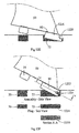
- An example of a variation can be seen when comparing
Figures 2C ,4C , and5C . In these examples,Figures 2A to 3C represent an example of acentral fin 50, where, as shown infigure 2C , thefin 50 is substantially perpendicular to thedevice 10. However, in contrast, thefins 50 ofFigures 4C and5C , are at an angle to the vertical of thedevice 10.Figure 4C is an example of a right-side fin, andFigure 5C is an example of a left side fin. Although the fins described are configured to be inserted at any angle to the vertical, in one particular example, the angle is 7 to 9 degrees from the vertical. - Accordingly, the
device 10 may also be varied to accommodate for the varying angle of insertion. As shown inFigures 4C and5C , thefirst cavity 15 may include an angled opposingwall 28, opposite to the cavity wall 25 (which is typically cavity wall where the extendingportion 35 protrudes there through). - In further examples,
Figures 6A to 6P show example of a device orfin plug 10, where in these examples, thedevice 10 would typically be used for a centre fin. It will be appreciated by persons skilled in the art that, as shown infigure 6M , the extendingportion 35 protrudes through thecavity wall 25 at a position where it can easily mate with the correspondinggrooved portion 65 of thefin 50. Thus, the extendingportion 35 need not necessarily protrude through at the centre of thecavity wall 25, and can, according to this particular example, be offset from the centre. - Additionally, the
device 10 shows fixation points 98 for fixing of grub screws or any other suitable fixing means, or the like, for further fixing thefin 50 to thedevice 10. It will be appreciated that the use of the grub screws or other suitable fixing means can allow for different types of fins to be fixed to thedevice 10. Thus in this particular example, the grub screw can be configured to extend into thefirst cavity 20 to further secure a base portion of thefin 50 within thefirst cavity 20. A similar grub screw can be used for thesecond cavity 75 where a grub screw is configured to extend into thesecond cavity 75 to further secure a tab, base portion, or the like of thefin 50 into thesecond cavity 75. -
Figures 7A to 7D are examples of thedevice 10 for use with a right side fin. Furthermore,Figures 8A to 8D are examples of thedevice 10 for use with a left side fin. Of particular note from these figures, it will be appreciated that the examples show that the devices when used for the side fins (such as the left and right fins) can be formed such that they are mirror images of each other. Furthermore,Figures 7B and8B show the angled opposingwall 28, to allow for an angled insertion of the respective fins. - In the examples shown herein, the
device 10 is shaped substantially as a figure-eight, such that at least one profile of the device has substantially, a figure-eight shape. In these examples, thefirst cavity 15 is located or formed within afirst end 12 of the figure-eight and thesecond cavity 75 is formed within thesecond end 14 of the figure-eight. - It will be appreciated by persons skilled in the art that the figure-eight shape of the
device 10 can provide advantages such allowing for thedevice 10 to form part of the water craft and further allowing the fin portions to be locked therein. The smooth edges of the figure-eight shape can also provide for an easier manufacturing process. However, it will be appreciated that the device is not limited to this shape and other shapes which provide the functionality of the cavities, are incorporated herein. -
Figures 9A to 9H show examples of acentre fin 50, for use with acentre device 10.Figures 10A to 10D show examples of aright fin 50, andFigures 11A to 11D show an example of aleft fin 50. Notably, the left and right fins may be mirror images of each other. - Notably, referring to the
fins 50, it will further be appreciated that although thefirst fin portion 15 and thesecond fin portion 90 can be or can include first and second tabs respectively, it will be appreciated that any base portion of thefin 50 may be configured to be insertable into the first andsecond cavities - Further examples of fixing means for the
second fin portion 90 and thesecond cavity 75 are shown inFigures 12A to 27B . Thus, in these examples the following variations are shown in the following paragraphs. -
Figure 12A shows thesecond fin portion 90 having aconvex edge 1210, mating with a correspondingconcave portion 1212 of thesecond cavity 75. -
Figure 12B shows thesecond fin portion 90 having aconcave edge 1214, mating with a correspondingconcave portion 1216 of thesecond cavity 75. -
Figure 12C shows a differentconcave edge 1218 on thesecond fin portion 90, mating with a protrudingconvex portion 1220 in thesecond cavity 75. -
Figure 12D shows a variation ofFigure 12A where thesecond fin portion 90 has a slantedconvex edge 1222 with a correspondingsecond cavity geometry 1224. -
Figure 12E shows an entire top edge of thesecond fin portion 90 being cut away 1226 and mating with a correspondingconvex edge 1228 of thesecond cavity 75. -
Figure 12F shows agroove 1230 or the like cut in the sides of thefin tab nose 1232 and being configured to correspond withpins 1234 from both sides of thesecond cavity 75. -
Figure 12G shows asingle pin 1236 being configured to be inserted into thesecond fin portion 90 to hold thefin portion 90 within thesecond cavity 75. -
Figure 12H shows arounded bottom edge 1238 of thesecond fin portion 90, protruding and mating with a correspondingconvex portion 1240 of thesecond cavity 75. -
Figures 13A to 13C show the insertion of thesecond fin portion 90 into thesecond cavity 75, where thesecond fin portion 90 has a spring-loaded undercut 1310. In these examples, the undercut 1310 retracts when thesecond fin portion 90 is inserted into the second cavity 75 (as shown inFigure 13B ), and then springs into acorresponding recess 1312 within thesecond cavity 75 when thefin portion 90 is in place (as shown inFigure 13C ). -
Figures 14A to 14C show the insertion of twopins 1410 on thesecond fin portion 90 into thesecond fin cavity 75, where the two pins surround a convex portion of thesecond cavity 75. The pins may also be formed from the undercutting of the fin tab nose. -
Figures 15A to 15C show a further example offlexes 1510 ordeformable members 1510 inserted in thesecond fin portion 90 to create an undercut which then mates by deforming with acorresponding shape 1512 of thesecond cavity 75. - In
Figures 16A to 18C thefront tab 90 detail in engaging with thesecond cavity 75 not only uses a variation in undercut profile to secure the front tab but also has the secondary function of creating a prescribed entry and exit angle for the fin into the fin plug. This secondary function may make it more difficult for a fin to release from a fin plug unintentionally during surfing if configured as perFigures 16A to 18C . -
Figures 16A to 16C show an example sequence of inserting thesecond fin portion 90 into thesecond cavity 75 by the use of anoval pin 1610. The fin plugsecond cavity 75 with theoval pin 1610 that may only allow thefront fin tab 90 to release when the corresponding oval shaped recess in thefront fin tab 90 is aligned in the direction of intended release, as shown by way of example inFigures 16A to 16C . -
Figures 17A to 17D show an example sequence of the use of apin 1710 in thetab 90 and atrack 1712 mechanism to insert thesecond fin portion 90 into thesecond cavity 75. Thetrack 1712 can be located in the side wall of thesecond cavity 75. -
Figures 18A to 18C shows the use of another mating of aconcave portion 1810 in thesecond fin portion 90 with aconvex portion 1812 of thesecond cavity 75. -
Figure 19 is an example of the use of two shallowstatic pins 1910 protruding from either side of thesecond cavity 75 side walls . The twopins 1910 each mate with respectiveshallow grooves 1920 of thesecond fin portion 90 as shown inFigure 19 . -
Figure 20 shows an example where therear fin tab 15 has a geometry or cut-out so as not to engage with thebarrel 35. In this example the front tab cut out 2010 is also configured to not engage with aprotrusion 2012. The fin ofFigure 20 may be fixed into the fin plug by use of fixing means such as grub screws in the fixation points 98 of the fin plug. -
Figures 21 ,23 and 24 show examples of various shaped cut-outs 2110 of thesecond fin portion 90 which then mate with corresponding shapedprotrusions 2112 of thesecond cavity 75. -
Figure 22 shows anextension 2210 of the baseline of thesecond fin portion 90 to be inserted into acorresponding cutout 2212 in thesecond cavity 75. -
Figures 25A to 25C show a sequence for arear fin tab 15 configuration that may allow thefin tabs respective cavities rear fin tab 15 engages with thebarrel 35. The rear tab geometry ofFigures 25A to 25C may be modified (not shown) to facilitate engaging with thebarrel 35 in this alternate embodiment. -
Figures 26A and 26B illustrate the securing of a fin to the fin plug where the fin has no rear fin tab. In this situation thefront fin tab 90 may engage with thesecond cavity 75 as shown withprotrusion 2512 andcorresponding recess 2510 or the engagement may be as described herein elsewhere. In addition the fin ofFigures 26A and 26B may be further securred into the fin plug by use of fixing means such as grub screws in the fixation points 98 of the fin plug. -
Figures 27A and 27B show a further example toFIGURE 20 where therear fin tab 15 also has a geometry or cut-out so as not to engage with thebarrel 35. Thefront fin tab 90 may engage with thesecond cavity 75 via different shapedcutouts 2510 in thesecond fin portion 90 mating with acorresponding protrusion 2512 of thesecond cavity 75. In addition the fin ofFigures 27A and 27B may be further securred into the fin plug by use of fixing means such as grub screws in the fixation points 98 of the fin plug. - Accordingly, it will be appreciated that the engagement means described herein, which is typically used to hold the second tab portion within the second cavity, can be of any form and can also include any attachment means such as magnets, or even a second biasing means (such as the rod and wheel-like member of the first cavity).
- In yet further examples, the device/fin plug described herein can be configured to receive an adapted fin. For example, the fin portion or base portion on the adapted fin, can be a separate element which is insertable as an adapter over a fin, in order to then be able to insert the fin into the device/fin plug as described herein. Example adaptors are shown in
Figures 28A to 28C . InFigures 28A1 and 28A2 , thefirst adaptor 2810 can be screwed in to the base of a tab-less fin. Alternatively infigures 28B1 and 28B2 thefirst adapter piece 2810 can be screwed in to the side of the tabs on a two-tab fin. Accordingly, in both instances, the geometry of the proposed new tab configuration is added through this extension. In yet a further example, as shown inFigures 28C1 and 28C2 , two holes can be drilled through the sides of the tabs on an existing 2-tab fin. Then, two pins (or plugs) 2812, 2814 can be screwed or press fitted in to place to form second and third adapter pieces. The result is two protruding pins from the sides of the tabs (thefront pin 2814 nesting under the front undercut area of the box front slot whilst therear pin 2812 interacts with the barrel which applies a downward and lateral force). - Although the illustrated fin plug is primarily intended to be used with water craft fins (e.g. surfboard fins) of the invention, so as to enable such fins to be easily and conveniently attached to, or detached from the fin plug (without the use of a tool), it is not limited to such use. For instance, other water craft attachment devices can be selectively attached to, or detached from, the relevant fin plug in substantially the same way as the abovementioned fins are attached or detached.
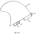
- An example of such other water craft attachment devices is the
hook device 100 shown inFigures 29A to 29H . As will readily be appreciated, this hook device is adapted to be connected to a surfboard (or other water craft) so that the surfboard (or other water craft) can be suspended from a horizontal supporting rod (or similar structure). - This
hook device 100 has afirst end 101 and asecond end 102. Ahook element 103 is located adjacent thefirst end 101 and aconnection portion 105 is located adjacent thesecond end 102. Anintermediate portion 106 is located between thehook element 104 and theconnection portion 105. - The
hook element 103 comprises a plurality ofperforations 104. A benefit of the perforations is that they reduce the weight of the device and less material is required when the device is manufactured (resulting in cost savings). - The
connection portion 105 comprises afirst tab 115 and asecond tab 190. Thefirst tab 115 and thesecond tab 190 are adapted to be inserted into thefirst cavity 20 and the second cavity 75 (respectively) of thefin plug 10. - The first tab includes a
grooved portion 165. Thisgrooved portion 165 is located on aside surface 170 of thefirst tab 115. Thegrooved portion 165 is typically configured to engage with the extendingportion 35 of thefin plug 10. Thus, in one example, a surface of the wheel-like member 35, which is typically a curved surface, is configured to site within the groovedportion 165. - It will be appreciated that although the
grooved portion 165 can be formed or shaped such that it substantially conforms or mates with the curved surface of the extending portion 35 (of the fin plug 1), strict conformance or mating is not necessary. In this example, thegrooved portion 165 is configured to roll over the extending portion 35 (of the fin plug 1) and the extendingportion 35 can then lock thefirst tab 115 into thefirst cavity 20. It will also be appreciated that when the locking action occurs and thefirst tab 115 is pushed into the cavity, therod 30 may bend and may remain slightly bent when applying the force to the extendingportion 35, which subsequently applies a force to thegrooved portion 165, in order to maintain thefirst tab 115 within thefirst cavity 20. In one particular example, either a lateral or a downward force, or a combination thereof can be applied to maintain thefirst tab 115 within thefin plug 10. - The
second tab 190 includes arecess 185. Thisrecess 185 is adapted to engage with theprotrusion 80 on the device 10 (within the second cavity 75). - According to one particular example, when inserting the
hook device 100 into thefin plug 10, thesecond tab 190 is inserted initially, where therecess 185 on thesecond tab 190 engages with theprotrusion 80 on the fin plug 10 (within the second cavity 75). Once thesecond tab 190 is in place, thefirst tab 115 is locked into thefirst cavity 20 by pushing down on thehook device 100 such that thegroove 165 engages with the extending portion 35 (of the fin plug 1), which is at least partially within thefirst cavity 20. - As can be seen from the drawings, the plane of the
hook element 103 is at right angles (normal to) the plane of theconnection portion 105. The effect of this is that, when a surfboard is connected to the hood device 100 (via the connection portion 105), the substantial plane of the surfboard will be substantially parallel to the plane of thehook element 103, thereby enabling a plurality of surfboards to be suspended from a supporting rod, in a sandwich-type formation (which results in improved space efficiencies). - Compatibility infills are illustrated in
figures 30A to 35C . The infills can be of two types, compatibility infills and full plug infills. A compatibility infill as illustrated infigures 30A to 32E can be used to fill in gaps or voids remaining between a fin and the first and / orsecond cavities fin plug 10. Such gaps can occur with the use of fins which were not originally intended for use with the fin plugs 10 as described here. For example fins as described with respect tofigures 28A to 28C with the use of adapters or other fins that can be used with thefin plug 10. The compatibility infill by filling a gap or a void of thefin plug 10 with the fin can improve the hydrodynamic performance about the fin and the fin plug, for example reduced hydrodynamic drag. The compatibility infill can also be used to exclude foreign matter such as sand from thefin plug 10 as well as improving the aesthetic appeal of the fin plug, the fin and the surfboard / water craft overall. -
Figures 30A to 30E are respective elevational views of rear, side, front, top and bottom for a centerfin compatibility infill 3010.Figures 30F to 30I are corresponding perspective illustrations of the centerfin compatibility infill 3010 where anexterior surface 3012, aside surface 3014, afront surface profile 3016, arear surface profile 3018 and abottom surface 3020 are shown. Thefront surface profile 3016 is adapted to engage with a fin engagement means 80 orledge portion 80 in thesecond cavity 75 of thefin plug 10, described in detail with respect tofigures 32A to 32E . -
Figures 31A to 31E are respective elevational views of rear, side, front, top and bottom for a sidefin compatibility infill 3110.Figures 31F to 31I are corresponding perspective illustrations of the sidefin compatibility infill 3110 where anexterior surface 3112, a side surface 3114, afront surface profile 3116, arear surface profile 3118 and a bottom surface 3120 are shown. Thefront surface profile 3116 is configured as described above for the centerfin compatibility infill 3010. Therear profile 3118 exists to replicate thefront profile 3116 on the alternate side fin plug, that is the "front"profile 3116 performs the same function on the left hand fin plug as the "rear"profile 3118 performs on the right hand fin plug. This allows a singlemoulded part 3110 to be used in either the right or left side fin plugs by simply flipping or otherwise rotating theside fin infill 3110. -
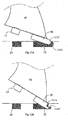
Figures 32A to 32E show a sequence of fitting the centerfin compatibility infill 3010 into thefin plug 10 with anotherfin 3210 not originally designed for thefin plug 10. Theinfill 3010 is inserted into thesecond cavity 75 as shown infigure 32B so that thefront surface 3016 of the infill engages with the fin engagement means 80. Theinfill 3010 is then pressed into thesecond cavity 75 until theexterior surface 3012 of theinfill 3010 is approximately flush with the top orexterior surface 3220 of thefin plug 10.Figure 32C shows the infill installed into theforward region 12 of thesecond cavity 75. The press fitting of theinfill 3010 is aided by selecting a material for the infill such as silicone rubber so that the rubber deforms for press fitting then reforms within thesecond cavity 75 to secure theinfill 3010 within thesecond cavity 75. The selection of silicone rubber is also advantageous for its resistance to corrosion in the marine environment. Other suitable materials for the infill can be a thermoplastic polyurethane (TPU), a thermoplastic elastomer (TPE), a polypropylene (PP) or other suitable materials as determined by a person skilled in the art. Infigures 32D and 32E the front 90 and rear 15 tabs of theother fin 3210 are shown being respectively inserted into the second 75 and first 20 cavities. Thefront tab 90 of thefin 3210 can also engage with therear surface profile 3018 of theinfill 3010 by press fitting, deformity and reforming of theinfill 3010. It will be readily appreciated that therear surface profile 3018 of the infill can be shaped or otherwise adapted so as to aid securing with thefront tab 90. Thefin 3210 can also be secured to thefin plug 10 as described previously above. - The fitting of the side
fin compatibility infill 3110 together with another side fin can also be done in a similar manner to that described for the centerfin compatibility infill 3010. -
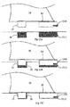
Figures 33 to 35 illustrate full plug infills to completely fill in the first 20 and second 75 cavities of thefin plug 10 when a fin is not present, as shown infigure 35C . The use of the full plug infills can be to improve the hydrodynamic performance, exclude foreign matter and improve aesthetic appeal as described above for the compatibility infills. Full plug infills can be particularly useful for surfboards that are capable of varying their multi-fin setup, for example a tri-fin and quad-fin set-ups in the one tri-quad fin surfboard. Tri-quad fin surfboards can have five fin plugs. The redundant one or two fin plugs, depending on whether a respective quad-fin or tri-fin setup is used, can be filled in with full plug infill/s. It will be readily appreciated that many multiple fin set-up surfboards can have redundant fin plug cavities for some fin set-ups. -
Figures 33A to 33E are respective elevational views of rear, side, front, bottom and top for a center finfull plug infill 3310 for thefirst cavity 20 of thefin plug 10.Figures 33F to 33I are corresponding perspective illustrations of the center finfull plug infill 3310 where anexterior surface 3312, aside surface 3314, afront surface profile 3316, arear surface profile 3318 and a bottom surface 3320 are shown. A small, circular boss orprotuberance 3322 on theside 3314 of thefull plug infill 3310 can be present to aid in securing theinfill 3310 in acavity 20 of the fin plug. Theinfill 3310 also features avertical member 3324 which can aid in removing theinfill 3310 from thefirst cavity 20 as well as aiding with the flush installation of theinfill 3310, described below with respect tofigures 35A to 35C . -
Figures 34A to 34E are respective elevational views of rear, side, front, bottom and top for a center finfull plug infill 3410 for thesecond cavity 75 of thefin plug 10.Figures 34F to 34I are corresponding perspective illustrations of the center finfull plug infill 3410 where anexterior surface 3412, aside surface 3414, afront surface profile 3416, arear surface profile 3418 and abottom surface 3420 are shown. A small, circular boss orprotuberance 3322 on theside 3414 of thefull plug infill 3410 can also be present to aid in securing theinfill 3410 in thesecond cavity 75 of thefin plug 10. Theinfill 3410 also features twovertical members infill 3310 from thefirst cavity 20 as well as aiding with the flush installation of theinfill 3310, described below with respect tofigures 35A to 35C . The twovertical members boss 3322; alternatively theboss 3322 may be placed on either of thevertical members - It will be readily appreciated that full plug infills can also be designed and made for side fin plugs.
-
Figures 35A to 35C show a sequence of fitting the two full plug infills 3310, 3410 into thefin plug 10. The full plug infills 3310, 3410 are pressed into theirrespective cavities exterior surfaces infills exterior surface 3220 of thefin plug 10. As described above the press fitting of the infills is aided by selecting a material for the infill such that the material deforms for press fitting then reforms within thecavities infills boss 3322 can also provide further securing within thecavities vertical members fin plug 10 by depressing theexterior surface 3412 of the full plug infills to allow at least part of the full plug infill to rise above theexterior surface 3220 of thefin plug 10. The full plug infills can then be easily removed manually. - The full plug infills can alternatively be made in a fuller profile so as to fill the cavities more completely and more securely. In this alternative embodiment the full plug infills can be removed with the aid of a tool and/or fingernail.
- Notably, it will be appreciated that although many different materials can be used for the
device 10, it can be formed of ABS (Acrylonitrile Butadiene Styrene, or any other plastics) or Zytel. Theside cap 57,cap 60 and end plug 55 can also be formed of the same material. Therod 30 is typically formed of any elastic material such as high grade stainless steel or titanium, which is also a robust material in watercraft as the material does not generally degrade or rust. The same robust material may also be used for the extendingportion 35. It will further be appreciated that thedevice 10 can be injection molded. - It will also be appreciated that the
hook device 100 can be formed from many different materials. Typically, this device will be formed from appropriate plastic materials which are relatively inexpensive and sufficiently strong for suspending a surfboard (or other water craft) from a supporting rod. - In this specification, terms denoting direction, such as vertical, up, down, left, right etc. or rotation, should be taken to refer to the directions or rotations relative to the corresponding drawing rather than to absolute directions or rotations unless the context require otherwise.
- Where ever it is used, the word "comprising" is to be understood in its "open" sense, that is, in the sense of "including", and thus not limited to its "closed" sense, that is the sense of "consisting only of". A corresponding meaning is to be attributed to the corresponding words "comprise", "comprised" and "comprises" where they appear.
Claims (12)
- A water craft fin (50) to be removably secured to a water craft fin plug (10) having distinct front and rear open cavities (75, 20) and a bridge section (95) therebetween,the front open cavity (75) of the fin plug (10) having a front cavity fin engagement means (80) comprising a protrusion in a front end of the front open cavity and a first recess between the protrusion and a base surface of the front open cavity (75); andthe rear open cavity (20) of the fin plug (10) having a resiliently protruding ring-shaped member (35) extending into the rear open cavity (20) from an elongate side surface of the rear open cavity (20);
the water craft fin (50) comprising:a base portion (18) having a front tab (90) and a rear tab (15) adapted to be received in the front open cavity (75) and the rear open cavity (20) respectively;the front tab (90) includes a nose section (85) at a front portion of the tab (90) which is adapted to engage with the first recess and the protrusion so as to be retained by the front cavity fin engagement means (80); andthe rear tab (15) includes a side surface (70) which is partially recessed at a forward location of the rear tab side surface , adapted to at least partially receive the resiliently protruding ring-shaped member (35) of the rear cavity (20);whereby at fin insertion the front tab (90) engages with the front cavity fin engagement means (80) and the fin pivots to insert the rear tab (15) into the rear cavity (20) and engage with the resiliently protruding ring-shaped member (35) such that the fin (50) is removably secured to the fin plug (10) by the fin engagement means (80) and the resiliently protruding ring-shaped member (35). - A fin (50) according to claim 1, wherein the rear tab (15) includes a lower tab portion and a lowermost surface, wherein the lower tab portion is between the partially recessed side surface (70) and the lowermost surface; and
wherein the rear tab (15) has a cross-sectional thickness that is relatively thick towards a top of the lower tab portion and relatively thin towards a bottom of the lower tab portion. - A fin (50) according to claim 1, wherein the rear tab (15) includes a transition surface between the recessed side surface (70) and a lowermost surface of the rear tab (15); wherein, when the fin (50) is inserted into the fin plug (10), the transition surface engages with the resiliently protruding ring member (35) before the recessed side surface engages with the resiliently protruding ring member (35).
- A fin (50) according to according to any one of the preceding claims, wherein the partially recessed side surface (70) includes a grooved portion (65); and
wherein the grooved portion (65) is adapted to at least partially receive the ring shaped member (35) when the rear tab (15) is in the fin plug (10). - A fin (50) according to any one of the preceding claims, wherein the partially recessed side surface (70) of the rear tab (15) includes an inclined surface section (16), the inclined surface section (16) being adapted to cooperate with the ring-shaped member (35) mounted to a resilient rod (30) of the fin plug (10), so as to cause a force, that is inwardly and laterally into the fin plug (10), to be applied to the rear tab (15) when the resilient rod (30) bends resiliently; and
wherein the force being applied is such that a removal of the rear tab (15) from the fin plug (10) is inhibited. - A fin (50) according to claim 5, wherein the inclined surface section (16) is located on the side surface (70) of the rear tab (15) to abut the ring-shaped member (35) of the fin plug (10) when the fin base portion (18) is in the fin plug (10).
- A fin (50) according to any one of the preceding claims, wherein the partially recessed side surface (70) is located on the rear tab (15) to abut the ring-shaped member (35) of the fin plug (10) when the rear tab (15) is in the fin plug (10).
- A fin (50) according to any one of the preceding claims, wherein in use the partially recessed side surface (70) cause:to bend a resilient rod (30) mounting the ring-shaped member (35) of the fin plug (10), andat least one of the ring-shaped member (35) and the resilient rod (30) of the fin plug (10) to rotate about a longitudinal axis of the resilient rod (30) ,when the fin rear tab (15) removably engages with the fin plug (10).
- A fin (50) according to any one of the preceding claims, wherein the nose section (85) of the front tab (90) includes a second recess which receives the protrusion of the front cavity (75) fin engagement means (80), to facilitate said engagement with the front cavity fin engagement means (80) and pivoting of the fin to insert the rear tab (15) into the rear cavity (20).
- A fin (50) according to claim 11 or 12, wherein a portion of the nose section (85) of the front tab (90) is adapted to underlie the front cavity (75) protrusion of the fin plug (10) to inhibit movement of the fin (50) when the front tab (90) and the rear tab (15) of the fin (50) are received within the fin plug (10).
- A fin (50) according to any one of the preceding claims, wherein the fin (50) includes a surface between the front tab (90) and the rear tab (15) which is adapted to abut the bridge section (95) of the fin plug (10).
- A fin (50) according to any one of the preceding claims, wherein the water craft is at least one of a surfboard, a surf craft, a sail board, a stand-up paddle board, a rescue board, a surf ski and a kayak.
Applications Claiming Priority (3)
| Application Number | Priority Date | Filing Date | Title |
|---|---|---|---|
| AU2012902939A AU2012902939A0 (en) | 2012-07-09 | FIn Plug for Water Craft | |
| PCT/AU2013/000738 WO2014008529A1 (en) | 2012-07-09 | 2013-07-05 | Fin plug for water craft |
| EP13816709.3A EP2870063B1 (en) | 2012-07-09 | 2013-07-05 | Fin plug for water craft |
Related Parent Applications (2)
| Application Number | Title | Priority Date | Filing Date |
|---|---|---|---|
| EP13816709.3A Division EP2870063B1 (en) | 2012-07-09 | 2013-07-05 | Fin plug for water craft |
| EP13816709.3A Division-Into EP2870063B1 (en) | 2012-07-09 | 2013-07-05 | Fin plug for water craft |
Publications (2)
| Publication Number | Publication Date |
|---|---|
| EP3486159A1 EP3486159A1 (en) | 2019-05-22 |
| EP3486159B1 true EP3486159B1 (en) | 2021-04-21 |
Family
ID=49915238
Family Applications (2)
| Application Number | Title | Priority Date | Filing Date |
|---|---|---|---|
| EP18212428.9A Active EP3486159B1 (en) | 2012-07-09 | 2013-07-05 | Fin for watercraft |
| EP13816709.3A Active EP2870063B1 (en) | 2012-07-09 | 2013-07-05 | Fin plug for water craft |
Family Applications After (1)
| Application Number | Title | Priority Date | Filing Date |
|---|---|---|---|
| EP13816709.3A Active EP2870063B1 (en) | 2012-07-09 | 2013-07-05 | Fin plug for water craft |
Country Status (9)
| Country | Link |
|---|---|
| US (3) | US9688365B2 (en) |
| EP (2) | EP3486159B1 (en) |
| JP (1) | JP6169691B2 (en) |
| CN (2) | CN108082412B (en) |
| AU (6) | AU2013204785C1 (en) |
| BR (1) | BR112015000453A2 (en) |
| ES (2) | ES2880371T3 (en) |
| PT (2) | PT3486159T (en) |
| WO (1) | WO2014008529A1 (en) |
Families Citing this family (26)
| Publication number | Priority date | Publication date | Assignee | Title |
|---|---|---|---|---|
| AU2013204785C1 (en) | 2012-07-09 | 2019-09-05 | Fin Control Systems Pty. Limited | Fin Plug for Water Craft |
| AU2013204755A1 (en) * | 2012-11-14 | 2014-05-29 | Fin Control Systems Pty. Limited | A Fin Plug for a Water Craft |
| AU2015230676B2 (en) * | 2014-03-11 | 2019-04-11 | Fin Control Systems Pty Limited | Securing mechanism for water craft fin |
| KR101607197B1 (en) * | 2014-06-11 | 2016-03-30 | (주)우성아이비 | Interchangeable fin-box |
| AU201612981S (en) * | 2016-06-02 | 2016-06-14 | Shapers Aust Pty Ltd | Surfcraft Fin |
| AU201612985S (en) * | 2016-06-02 | 2016-06-14 | Shapers Aust Pty Ltd | Surfcraft Fin |
| AU201612986S (en) * | 2016-06-02 | 2016-06-14 | Shapers Aust Pty Ltd | Surfcraft Fin |
| AT518838B1 (en) | 2016-06-24 | 2019-09-15 | Firefin Gmbh | Fin arrangement and water sports equipment |
| US20180001460A1 (en) * | 2016-06-30 | 2018-01-04 | Daniel Ray Foucault | Device for applying railroad anchors |
| AT519942B1 (en) * | 2017-04-25 | 2020-01-15 | Riegerbauer Hermann | fin |
| US10694082B2 (en) * | 2017-05-02 | 2020-06-23 | John Immel | Fin shaped underwater camera housing and system incorporating same |
| US10173757B2 (en) | 2017-05-11 | 2019-01-08 | Jimmy Styks Llc | Watersport board fins with fin retention systems and watersport boards containing the same |
| TWI636919B (en) * | 2017-09-07 | 2018-10-01 | 葉宗殷 | Surfboard with fin assembly |
| US10279874B1 (en) | 2017-11-01 | 2019-05-07 | John Field | Quick-connect fin retention system for a water craft |
| US20190145445A1 (en) * | 2017-11-14 | 2019-05-16 | David L. McClung | Clamping assembly |
| US20190144096A1 (en) * | 2017-11-14 | 2019-05-16 | David L. McClung | Clamping assembly |
| US20190225315A1 (en) * | 2017-11-14 | 2019-07-25 | David L. McClung | Clamping assembly |
| AU2018271266B2 (en) | 2018-01-17 | 2019-04-04 | O'Brien, Kristian Michael MR | Watercraft Fin Removal Tool and Method |
| US10633060B2 (en) * | 2018-02-28 | 2020-04-28 | Fin Puller | Tool device system and method for watercraft fin insertion and removal |
| US10773775B2 (en) * | 2018-10-25 | 2020-09-15 | Robert A. Stehlik | Foil strongbox |
| WO2020150769A1 (en) * | 2019-01-21 | 2020-07-30 | Dynamik Pty Limited | Toolless fin mount assembly |
| US11345448B2 (en) * | 2019-06-11 | 2022-05-31 | John DeCourcey Milne | Fin fixing system |
| US11584485B2 (en) * | 2020-10-12 | 2023-02-21 | Paul Thomas | Enhanced planning device and systems |
| USD1020952S1 (en) * | 2021-11-18 | 2024-04-02 | Darren Watson | Fin plug assembly for a surfcraft |
| US20230174200A1 (en) * | 2021-12-03 | 2023-06-08 | Ho Sports Company, Llc | Foldable fin for watersport equipment |
| CN114228918B (en) * | 2022-02-09 | 2023-04-11 | 惠州城市职业学院(惠州商贸旅游高级职业技术学校) | Surfboard and high-performance surfboard tail rudder thereof |
Citations (6)
| Publication number | Priority date | Publication date | Assignee | Title |
|---|---|---|---|---|
| DE1713616U (en) | 1955-06-03 | 1955-12-22 | Fritz Bohmer | ROLLER SNAPPER FOR FURNITURE. |
| DE8610401U1 (en) | 1986-04-16 | 1986-06-12 | Fichtner, Hans, 8124 Seeshaupt | Sword for a sailing board |
| US5328397A (en) | 1992-03-09 | 1994-07-12 | Fin Control Systems Pty. Limited | Surf fin fixing system |
| US6764364B1 (en) | 2002-10-21 | 2004-07-20 | Scott Noble Hickman | Surf craft snap-in fin system |
| US7121911B1 (en) | 2005-07-26 | 2006-10-17 | Scott Noble Hickman | Surfcraft removable fin system improved plug installation |
| US20100233921A1 (en) | 2007-07-20 | 2010-09-16 | Katsuyoshi Kumano | Fin attachment structure |
Family Cites Families (249)
| Publication number | Priority date | Publication date | Assignee | Title |
|---|---|---|---|---|
| DE1121541B (en) | 1955-01-15 | 1962-01-04 | Beteiligungs & Patentverw Gmbh | Drop trolley for conveyor belt lines |
| DE1038517B (en) | 1956-03-27 | 1958-09-11 | Erich Kiefer | Perforated drum dryer |
| CH508565A (en) | 1966-11-30 | 1971-06-15 | Kureha Chemical Ind Co Ltd | Prepn of vinyl chloride from acetylene ethylene formed |
| JPS461639Y1 (en) * | 1967-08-17 | 1971-01-20 | ||
| US3516099A (en) | 1968-06-17 | 1970-06-23 | Thomas H Morey | Mounting structure for removable surfboard fin |
| US3564632A (en) | 1968-10-17 | 1971-02-23 | William L Bahne Jr | Adjustable surfboard fin holder |
| US3579681A (en) | 1969-04-01 | 1971-05-25 | Karl D Pope | Sectional and longitudinally adjustable surfboard fin assembly |
| US3659300A (en) | 1969-07-25 | 1972-05-02 | W A V E Corp | Fin attachment structure for surfboards |
| US3585663A (en) | 1969-08-13 | 1971-06-22 | W A V E Corp | Longitudinally adjustable surfboard fin with self-contained locking mechanism |
| US3879782A (en) | 1973-08-06 | 1975-04-29 | Clifford Clinton Oliver | Surfboard with removable tail surface area portion |
| US3890661A (en) | 1974-02-21 | 1975-06-24 | Robert F Johnson | Surfboard rudder-fin combination |
| US3965514A (en) | 1975-01-30 | 1976-06-29 | Shafer Arthur B | Adjustable and/or removable fin for surfboards |
| US4044416A (en) | 1976-06-14 | 1977-08-30 | Brewer Charles A | Surfboard with adjustable fin |
| DE2722547A1 (en) | 1977-05-18 | 1978-11-23 | Hans Joachim Prof Dr Petzold | Tilt adjustment for sailing boat centre-board - uses endless belt drive linked to board and has slider control with retaining ratchet |
| GB2010189A (en) | 1977-12-16 | 1979-06-27 | Marker Hannes | Centre boards |
| DE3045412A1 (en) | 1978-09-29 | 1982-07-01 | Hannes 8100 Garmisch-Partenkirchen Marker | Sail-board dagger board box - has one guideway edge tangential to hull recess edge, with board trunnions deformed to enter |
| US4320546A (en) | 1979-07-23 | 1982-03-23 | Knox Carleton R | Surfboard |
| DE2932750A1 (en) | 1979-08-13 | 1981-03-26 | Hannes 82467 Garmisch-Partenkirchen Marker | Elastic mounting for wind surfer keel - has pivoted coupling to handgrip with access through top of board |
| DE2933802A1 (en) | 1979-08-21 | 1981-03-12 | Hannes 8100 Garmisch-Partenkirchen Marker | Sail-board dagger board housing allowing various board positions - has pin and groove arrangement holding spacer plugs when board is in place |
| FR2476587A1 (en) | 1980-02-22 | 1981-08-28 | Diziere Bernard | NEW DEVICE FOR FASTENING AN AILERON OR A DRIFT ON A SAILBOARD |
| US4325154A (en) | 1980-03-31 | 1982-04-20 | Collum Jr William E | Surfboard fin |
| DE3016927A1 (en) | 1980-05-02 | 1981-11-05 | Armin Dipl.-Ing. Gohritz | Nozzle-type surf-board stabilising fin - consists of low-profile convergent nozzle with dorsal connecting plate modifiable to suit board |
| DE3107896A1 (en) | 1980-11-14 | 1982-09-16 | AKUTEC Angewandte Kunststofftechnik GmbH, 8000 München | Sailboard with a fastening arrangement |
| DE3043052A1 (en) | 1980-11-14 | 1982-07-08 | AKUTEC Angewandte Kunststofftechnik GmbH, 8000 München | SAILING BOARD WITH A FIN FIXING ARRANGEMENT |
| DE3043496C2 (en) | 1980-11-18 | 1984-07-19 | Aquata Gesellschaft für Wassersport und Meerestechnik mbH &Co, 1000 Berlin | Arrangement for holding a fin in the fin box of sailboards |
| DE3043734A1 (en) | 1980-11-20 | 1982-07-08 | Dieter 7505 Ettlingen Frank | Sail-board with variable-length hull - has long forward and short after parts rigidly but releasably joined, both parts having fins underneath |
| US4379703A (en) | 1981-05-04 | 1983-04-12 | California Fin Systems | Apparatus for securing fins to a surfboard |
| BE888703A (en) | 1981-05-07 | 1981-11-09 | Herstal Sa | STABILIZER FOR SAILBOARDS AND THE LIKE |
| AU8415382A (en) | 1981-05-27 | 1982-12-02 | John Robert Davies | Fin for buoyant support |
| US4421492A (en) | 1981-06-16 | 1983-12-20 | Leva Donn W | Adjustable fin system |
| DE3126371C2 (en) | 1981-07-03 | 1986-04-03 | Mistral Windsurfing AG, Nürensdorf | Device for course stabilization and reducing drift of watercraft, in particular sword or fin for sailing boards |
| AU8447182A (en) | 1981-07-15 | 1983-01-20 | Victor Christian Ford | Surf board |
| JPS5815032A (en) | 1981-07-17 | 1983-01-28 | Toshiba Corp | Manufacturing apparatus for tantalum pentoxide |
| FR2510968A1 (en) | 1981-08-06 | 1983-02-11 | Mazerot Patrick | Keel fin fixing for sail board - is adjustably fitted in slot in board via pin and screw fixings |
| AU8599282A (en) | 1981-08-12 | 1983-02-17 | Blaxell, T. | Surfboard |
| DE3149288A1 (en) | 1981-12-12 | 1983-08-25 | Oosthuizen, Johannes H., Melbourne | Swivel mechanism for surfboards and windsurfing boards |
| DE3206057C2 (en) | 1982-02-19 | 1984-02-02 | Cowabanga Sportartikel Handelsgesellschaft mbH, 8000 München | Holder for the fin of a sail surfer |
| US4493665A (en) * | 1982-06-07 | 1985-01-15 | Liddle Edward M | Hydrofoil |
| DE3239441A1 (en) | 1982-10-25 | 1984-05-24 | Heko Kunststoffteilevertriebs GmbH, 8091 Ramerberg | Fin box for a surfboard |
| DE3246126A1 (en) | 1982-12-13 | 1984-06-14 | Franz 8011 Neukeferloh Hegele | Fin for a windsurfing board |
| FR2539377A1 (en) | 1983-01-18 | 1984-07-20 | Ellipse | Individually manufactured sailboard |
| DE3307412A1 (en) | 1983-03-02 | 1984-09-06 | Franz 8011 Neukeferloh Hegele | Device for the releasable attachment of a skeg to a sailboard |
| FR2546243A1 (en) | 1983-05-16 | 1984-11-23 | Lopez Francis | Device for removably fastening a sailboard or surfboard fin or centre board |
| DE3326894C2 (en) | 1983-07-26 | 1985-08-22 | Klepper Beteiligungs Gmbh & Co Bootsbau Kg, 8200 Rosenheim | Fin with clamp bracket |
| US4493655A (en) | 1983-08-05 | 1985-01-15 | Groff James W | Radio-controlled teaching device |
| DE3339686A1 (en) | 1983-11-02 | 1985-05-09 | A. Börner GmbH, 5561 Landscheid | Device for adjusting the position of members fastened to a surfboard |
| WO1985003237A1 (en) | 1984-01-26 | 1985-08-01 | Star Fin Pty. Limited | Surfboard and fin |
| SE8401506L (en) | 1984-03-19 | 1985-09-20 | Bengt Silfversparre | DEVICE FOR CHANGING THE SIZE OF THE BOTTOM NEWS AND FORM OF A WINDSURING WIDTH |
| DE3425233A1 (en) | 1984-07-09 | 1986-01-16 | Mistral Windsurfing AG, Nürensdorf | Device for stabilising the direction of travel of watercraft, in particular a centreboard or fin for windsurfing boards |
| GB8422952D0 (en) | 1984-09-11 | 1984-10-17 | Hunt J | Performance wing |
| DE3440553A1 (en) | 1984-11-07 | 1985-03-28 | Wolf-Dietrich 2300 Altenholz Zander | Variable keel-fin system for a surfboard |
| DE3442921A1 (en) | 1984-11-24 | 1986-06-05 | Gerd-Peter 2242 Büsum Ferring | Fin for fast watercraft such as, in particular, surfboards |
| FR2576867A1 (en) | 1985-02-06 | 1986-08-08 | Lepoen Francois | Sailboard aileron equipped with a depth regulator |
| US4733496A (en) | 1986-02-18 | 1988-03-29 | Peter Wallner | Pivoting surfboard fin |
| FR2594785B3 (en) | 1986-02-21 | 1988-07-22 | Cessou Yves Michel | STABILIZATION AND GUIDANCE DEVICE FOR A FLOATING NAUTICAL MACHINE |
| US4701144A (en) | 1986-03-13 | 1987-10-20 | Dewitt Iii Glen A | Breakaway surfboard fin holder |
| DD258710A3 (en) | 1986-03-25 | 1988-08-03 | Ammendorf Waggonbau | SWORD BOX TRAINING FOR RECEIVING A SWORD BOX INSERT, ESPECIALLY ON SAILBOARDS |
| DE3621933A1 (en) | 1986-06-30 | 1988-01-07 | Mistral Windsurfing Ag | Lip arrangement for a sailboard |
| DE3634445A1 (en) | 1986-10-09 | 1988-04-14 | Willibald Hergeth | Fin for a surfboard |
| US4804347A (en) | 1987-01-28 | 1989-02-14 | Ross Melvin C | Surfboard fin mount |
| AU8118387A (en) | 1987-02-06 | 1988-03-10 | John Gudgeon | Improved fin assembly |
| ES2004721A6 (en) | 1987-04-03 | 1989-02-01 | Miro Bravo Vicente | Device for adjusting the proximity of a trailer to a tractor |
| JPH02502987A (en) | 1987-04-13 | 1990-09-20 | ビーチャム、クリストファー ジェームズ | Flange fin for boats |
| NL8701265A (en) | 1987-05-27 | 1988-12-16 | Wilhelmus Aloysius Maria Van H | FIN OR SWORD FOR SAILING VESSEL, IN PARTICULAR A SAILBOARD. |
| US4850917A (en) | 1987-08-10 | 1989-07-25 | Wilson Kurt D | Sailboard fin |
| DE3729065A1 (en) | 1987-09-01 | 1989-03-09 | Peter Rohr | Fin with clamp fastening |
| ES2021662B3 (en) | 1987-09-21 | 1991-11-16 | Schutz-Werke Gmbh & Co Kg | LIP SEAL FOR THE GARDEN BOX OF A SURF SAILBOARD |
| US4789368A (en) | 1987-09-30 | 1988-12-06 | Onofrio Vincent G D | Rescue fin |
| US4846745A (en) | 1988-01-20 | 1989-07-11 | Lobe Henry J | Sailboard fin retaining member |
| US4964826A (en) | 1988-01-20 | 1990-10-23 | Lobe Henry J | Sailboard fin retaining member |
| DE3801747A1 (en) | 1988-01-22 | 1989-08-03 | Brian Hinde | Fin box with a fin for surfboards |
| US4854904A (en) | 1988-06-29 | 1989-08-08 | Wahl Eric R | Sailboard with adjustable keel mechanism |
| CH675567A5 (en) | 1988-07-13 | 1990-10-15 | Jean Bouldoires | Fin for surfboard with elastic rear region - hinges on top side of bottom section in fin passing recess |
| CH674826A5 (en) | 1988-07-14 | 1990-07-31 | Jean Bouldoires | |
| WO1990002589A1 (en) | 1988-09-14 | 1990-03-22 | Selwyn Charles Burrows | An improved fin fitting method |
| FR2639897B1 (en) | 1988-12-02 | 1991-03-01 | S R Ind | DEVICE FOR ATTACHING A FIN TO THE SURFACE OF A WINDSURF BOARD OR THE LIKE |
| GB2227461A (en) | 1989-01-31 | 1990-08-01 | Robert J C Brookes | Emergency folding fin |
| US4904215A (en) | 1989-02-09 | 1990-02-27 | Fiberfoam Inc. | Surfboard fin retainer |
| DE3907876A1 (en) | 1989-03-10 | 1990-09-13 | Mistral Windsurfing Ag | Sailboard with an adjustable fin (skeg) |
| EP0435974A1 (en) | 1989-05-09 | 1991-07-10 | Wolf-Dietrich Zander | Device for releasably fastening a fin shaft |
| US5032096A (en) | 1989-08-10 | 1991-07-16 | Scott David A | Laminar device and method for making same |
| US5148761A (en) | 1989-09-29 | 1992-09-22 | Bic Corporation | Daggerfin adjustable sailboard skeg |
| FR2659931A1 (en) | 1989-12-01 | 1991-09-27 | Bachelier Bernard | Device allowing the fastening and adjustment of a sailboard fin |
| DE4038517A1 (en) | 1989-12-06 | 1991-06-13 | Zander Wolf Dietrich | Sailboard fin-mounting adaptor - has recess of cross=section matching fin shank and fits in bottom recess |
| DE3943407A1 (en) | 1989-12-30 | 1991-07-04 | Scharwaechter Gmbh Co Kg | DOOR FASTENER FOR MOTOR VEHICLE DOORS |
| WO1991015395A1 (en) | 1990-04-10 | 1991-10-17 | Posi Trak Channel Systems | Surfboard control ridge |
| WO1991017080A1 (en) | 1990-04-30 | 1991-11-14 | Robert James Cross | Variable angle fin |
| US5176096A (en) | 1990-05-18 | 1993-01-05 | F2 International Ges.M.B.H. | Assembly for fastening a fin to a sailboard |
| DE4121541A1 (en) | 1990-07-31 | 1992-02-06 | Liborio Strazzeri | Rudder for wind surfer - has two principal parts of forward fixed element and rear movable element connected to control shaft |
| DE4029938C1 (en) | 1990-09-08 | 1992-01-09 | Schuetz-Werke Gmbh & Co Kg, 5418 Selters, De | |
| FR2667292A1 (en) | 1990-09-28 | 1992-04-03 | Bic Sport | Fin for nautical craft board and system for fixing it |
| US5133681A (en) | 1991-05-10 | 1992-07-28 | Lobe Henry J | Frangible sailboard fin retaining member |
| GB2255937B (en) | 1991-05-21 | 1994-11-09 | Andrew Thomas Kinnaird | Sailboards |
| US5176553A (en) | 1991-05-22 | 1993-01-05 | Tuttle Lawrence J | Sailboard fin box adapter |
| US5242322A (en) | 1991-06-03 | 1993-09-07 | John P. Chellemi | Safety fin water sports boards |
| DE4122000C1 (en) | 1991-07-03 | 1992-10-29 | Schuetz-Werke Gmbh & Co Kg, 5418 Selters, De | Fin keel mount for surfboards - has U=shaped cross=section with two side walls, slightly inclined outwards from mount bottom |
| DE4135173C1 (en) | 1991-10-24 | 1993-01-14 | Peter 8990 Lindau De Veh | |
| US5306188A (en) | 1991-11-06 | 1994-04-26 | Surfco Hawaii | Method of applying a safety/maneuver enhancing fin to a surfboard |
| US5273472A (en) | 1991-11-06 | 1993-12-28 | Surfco Hawaii | Surfboard fins with flexible edges |
| US5215488A (en) | 1992-01-22 | 1993-06-01 | Bailey Steven J | Locking device for releasably retaining fins onto sailboards and like water craft |
| US5464359A (en) * | 1992-03-09 | 1995-11-07 | Fin Control Systems Pty. Limited | Surf fin fixing system |
| AU669096B3 (en) | 1992-03-09 | 1996-05-23 | Fin Control Systems Pty. Limited | Surf fin fixing system |
| DE4219213C2 (en) | 1992-06-12 | 1995-04-20 | Loehr & Bromkamp Gmbh | Bearing arrangement for a wheel hub-constant velocity joint unit |
| DE9212799U1 (en) | 1992-09-23 | 1993-05-13 | Zistl, Peter, 8021 Strasslach, De | |
| FR2698673B1 (en) | 1992-12-02 | 1995-01-20 | Skf France | Freewheel mounting in tandem with single central bearing. |
| AU709493B2 (en) | 1993-05-07 | 1999-08-26 | Hwwc Holdings Limited | Vegetation control method and apparatus |
| US5356324A (en) | 1993-09-13 | 1994-10-18 | Cunningham Eugene F | Retractable, and adjustable fin box mechanism |
| AUPM299693A0 (en) | 1993-12-15 | 1994-01-20 | Newline Surf Pty Ltd | A fin assembly |
| US5464369A (en) | 1994-02-25 | 1995-11-07 | Johnson Service Company | Method and apparatus for estimating the rate at which a gas is generated within an enclosed space |
| FR2718705A1 (en) | 1994-04-14 | 1995-10-20 | Menetrier Vincent | Temporary fixing system for fin of waterborne craft |
| WO1995031366A1 (en) | 1994-05-17 | 1995-11-23 | Robert John Waters | A fin unit |
| US5493989A (en) | 1994-06-27 | 1996-02-27 | Anderson; Steven C. | Adjustable fin box system |
| US5503581A (en) | 1995-01-04 | 1996-04-02 | Mccullough; Robert P. | Apparatus for adjustable fin and fin block |
| AU693962B2 (en) | 1995-01-06 | 1998-07-09 | Jim Banks | Pivotable fin system |
| US5649846A (en) | 1995-01-06 | 1997-07-22 | Harper; Derek | Pivotable fin system |
| US5597337A (en) | 1995-02-21 | 1997-01-28 | The United States Of America As Represented By The Secretary Of The Navy | Quick change fin assembly for buoyant test vehicles |
| US5480331A (en) | 1995-04-17 | 1996-01-02 | John R. Nickel | Flexible surfboard fin |
| US5567190A (en) | 1995-05-22 | 1996-10-22 | Oates; Kenneth W. | Variable angle of attack finbox assembly for surfboards and the like |
| FR2744981A1 (en) | 1996-02-19 | 1997-08-22 | Thuault Xavier | Damper for windsurfing board wing setting on sail-assisted wind surfboards |
| AUPN922296A0 (en) | 1996-04-12 | 1996-05-02 | Ladd, Paul Vincent | Improved keel system on sailcraft and hitherto unknown, adaptions on motorised craft and vessels |
| DE19622223A1 (en) | 1996-06-03 | 1997-12-04 | Colin Patterson | Surf or sail board and process for its manufacture |
| AUPO269596A0 (en) | 1996-10-01 | 1996-10-24 | Sunbum Pty. Limited | Removable surf fin system |
| AU718340B2 (en) | 1996-10-01 | 2000-04-13 | Sunbum Pty. Limited | Removable surf fin system |
| US5830025A (en) | 1997-09-15 | 1998-11-03 | Fleming; Marc W. | Fin box for a water sports board and method of installation |
| GB2346843B (en) | 1997-10-27 | 2002-01-09 | Pat Tech Pty Ltd | Fin assembly |
| US20020039866A1 (en) | 1997-12-09 | 2002-04-04 | Pat-Tech Pty Ltd | Fin assembly |
| US5934962A (en) | 1998-01-20 | 1999-08-10 | Daum; Terry R. | Shallow draft surfboard fin mount |
| AUPP210698A0 (en) | 1998-03-02 | 1998-03-26 | Webber, Gregory Mark | Fin |
| US6106346A (en) | 1998-06-17 | 2000-08-22 | Bolen; Robert | Stabilizing fin for a water planing device |
| US6767266B2 (en) | 1998-06-17 | 2004-07-27 | Robert Bolen | Stabilizing element for use on mobile devices |
| US5951347A (en) | 1998-08-03 | 1999-09-14 | Surfco Hawaii | Watersport board fin construction |
| US5934963A (en) | 1998-08-06 | 1999-08-10 | Frizzell; Marvin Dean | Surfboard fin quick release system |
| US5997376A (en) | 1998-11-24 | 1999-12-07 | Block; Larry A. | Surboard fin mounting system |
| FI109278B (en) | 1998-11-25 | 2002-06-28 | Veikkaus Ab Oy | Method and arrangement for organizing electronic instant lottery |
| DE19854550C5 (en) | 1998-11-26 | 2011-03-17 | Hauni Maschinenbau Ag | Resonator housing for microwaves |
| AUPP744198A0 (en) * | 1998-12-01 | 1998-12-24 | Milne, John De Courcey | Surfboards and improvements to surfboards |
| FR2792280B1 (en) | 1999-04-13 | 2001-06-01 | Xavier Thuault | BOARD-HYDROPTERY VEHICLE MACHINE, SUPPORTING ON FOUR CARRIER POINTS, PROVIDED WITH A HYDRODYNAMIC AILER SETTING DAMPING DEVICE |
| GB9908516D0 (en) | 1999-04-15 | 1999-06-09 | Hicks Steve | Surfboard fin system |
| US6053789A (en) | 1999-05-28 | 2000-04-25 | Miyashiro; Lawrence | Surfboard fin pivotal mechanism |
| US6386933B1 (en) | 1999-09-30 | 2002-05-14 | Stephen S. Rewald | Enhanced customizable surfboards with adjustable fins and methods for making the same |
| US6551157B1 (en) | 1999-11-02 | 2003-04-22 | Lee Bishop | Water vehicle stabilizer and accelerator |
| US6213004B1 (en) | 1999-12-08 | 2001-04-10 | Gene Franco | Portable broiling device |
| US6244921B1 (en) | 2000-01-24 | 2001-06-12 | Karl D. Pope | Fin attachment system allowing roll angle alignment |
| AUPQ569200A0 (en) | 2000-02-18 | 2000-03-09 | Burns, Steve Daniel | Hydrodynamic device |
| AUPQ637700A0 (en) | 2000-03-22 | 2000-04-15 | Low Pressure Systems | Spring locking surfboard fin system |
| US6247985B1 (en) | 2000-08-28 | 2001-06-19 | Larry A. Block | Surfboard box cover |
| FR2823117A1 (en) | 2000-11-14 | 2002-10-11 | Pharmascience Lab | PHARMACEUTICAL OR COSMETIC COMPOSITION AND USE OF AT LEAST ONE ACTIVE COMPOUND FOR INHIBITING MIGRATION OF LANGERHANS CELLS |
| AU9711301A (en) | 2000-12-08 | 2002-06-13 | Smith, David Jonathan | Detachable fin system |
| AU2002220370A1 (en) | 2000-12-11 | 2002-06-24 | Rosebank Holdings Pty Ltd | Self-adjusting board fin |
| AUPR447401A0 (en) | 2001-04-18 | 2001-05-17 | Macnamara Marketing Pty Ltd | A fin assembly |
| US6439940B1 (en) | 2001-04-24 | 2002-08-27 | Alexander Pouchkarev | Fin and watercraft system |
| US7108571B2 (en) | 2001-06-29 | 2006-09-19 | Dean Geraghty | Method and apparatus for attaching a fin to a small watercraft |
| DE10132721C1 (en) | 2001-07-05 | 2003-01-23 | Horn P Hartmetall Werkzeugfab | cutter |
| FR2829046B1 (en) | 2001-08-28 | 2005-01-14 | Commissariat Energie Atomique | METHOD OF GRAFTING AND GROWING A CONDUCTIVE ORGANIC FILM ON A SURFACE |
| US6695662B2 (en) | 2001-11-07 | 2004-02-24 | Benjamin D. Kelley | Surfing craft with removable fin |
| US20030092333A1 (en) | 2001-11-13 | 2003-05-15 | Mccausland Bill | Removable and adjustable surf fin system |
| US20030092334A1 (en) | 2001-11-13 | 2003-05-15 | Mccausland Bill | Removable and adjustable surf fin system |
| AU2003201196B2 (en) | 2002-01-14 | 2009-11-05 | C & C Fin Designs Pty Ltd | A fin assembly |
| US6691537B2 (en) | 2002-02-22 | 2004-02-17 | Calvin Conrad Tan | Sportsboard locking apparatus |
| JP3633908B2 (en) | 2002-04-16 | 2005-03-30 | 義一 相川 | Marine board fin mounting member and marine board fin mounting structure |
| US6722764B2 (en) | 2002-04-29 | 2004-04-20 | Xerox Corporation | Feed guidance and identification for ink stick |
| AUPS216302A0 (en) | 2002-05-07 | 2002-06-06 | Batt, Michael | Surfboard fin adjustment system |
| US6752674B2 (en) | 2002-05-23 | 2004-06-22 | Oam, Llc | Sportboard fin attachment system |
| US6595817B1 (en) | 2002-06-17 | 2003-07-22 | Kung-Chao Chang | Surfboard |
| US20030236039A1 (en) | 2002-06-19 | 2003-12-25 | Banys Victor Julio | Coupling keel for surfboards and the like |
| JP2005532647A (en) | 2002-07-08 | 2005-10-27 | コーニンクレッカ フィリップス エレクトロニクス エヌ ヴィ | Medium drive clamping apparatus provided with communication means |
| US6991503B2 (en) | 2002-07-17 | 2006-01-31 | Antonio Garcia | Constructive disposition of adjustment of the removable lateral fins in surfboard |
| US6746292B2 (en) | 2002-10-09 | 2004-06-08 | David G. Panzer | Bottom fin for a watersports board |
| WO2004035377A1 (en) | 2002-10-17 | 2004-04-29 | Decourcey Pty Ltd | Surfboard fin box |
| US20040092180A1 (en) | 2002-11-07 | 2004-05-13 | Turkington Britt Keith | Surfboard fin |
| US6918806B2 (en) | 2002-12-19 | 2005-07-19 | Surfco Hawaii | Safety fin over mold system and safety fin sleeve for surfboard and other recreational vehicles |
| US20040248482A1 (en) | 2003-06-09 | 2004-12-09 | Rosebank Holdings Pty. Ltd. | Self-adjusting board fin |
| GB0315841D0 (en) | 2003-07-05 | 2003-08-13 | Scopenext Ltd | Variable dose dispenser pump |
| AU2004203516A1 (en) | 2003-07-30 | 2005-02-17 | Ding Goes Pty Ltd | A plug for a surf craft |
| US6837763B1 (en) | 2003-08-08 | 2005-01-04 | William T. Masteller | Adjustable fin positioning system |
| JP2005074026A (en) | 2003-09-01 | 2005-03-24 | Goddess International Kk | Method for fixing/removing fin on/from surfboard or the like |
| US6935910B2 (en) | 2003-09-12 | 2005-08-30 | John Laine | Watersport board fin assembly and methods of using same |
| US20050064775A1 (en) | 2003-09-22 | 2005-03-24 | William White | Surfboard fin box with detachable, leashed fin |
| US7117699B2 (en) | 2003-10-01 | 2006-10-10 | Bistline Donald A | Method and apparatus for securing a sports board fin to a sports board |
| JP2005112206A (en) | 2003-10-08 | 2005-04-28 | Goddess International Kk | Method of attaching and detaching fin of surfboard and the fin |
| US7001236B2 (en) | 2003-12-23 | 2006-02-21 | Blake Jr David T | Dynamic fin system for watercraft |
| US20050142961A1 (en) | 2003-12-29 | 2005-06-30 | Tan Calvin C. | Sportsboard locking arrangement |
| US6896570B1 (en) | 2004-03-04 | 2005-05-24 | O'keefe Thomas L. | Fin for a watersport board |
| USD502522S1 (en) | 2004-03-05 | 2005-03-01 | Dalton Sperafico | Fin insert for a surfboard |
| WO2005085058A1 (en) | 2004-03-05 | 2005-09-15 | Surfing Hardware International Holdings Pty Ltd | Fin plug |
| WO2005105566A1 (en) | 2004-04-30 | 2005-11-10 | Berenguer Monzon Pedro | Articulated device for connecting skegs to rigid surfboards |
| US20050272326A1 (en) | 2004-06-02 | 2005-12-08 | Hopper Brian D | Fin mounting system |
| US20050287222A1 (en) | 2004-06-24 | 2005-12-29 | Henry Aoki | Method for producing water containing extracted ingredients from plant, animal, or mineral matter |
| US20050287888A1 (en) | 2004-06-24 | 2005-12-29 | Tom Balester | Surfboard fin assembly |
| NL1026677C2 (en) | 2004-07-19 | 2006-01-23 | Klaas Boudewijn Van Gelder | Self-adjusting asymmetrical keel, sword, or rudder for a vessel. |
| US7285031B2 (en) | 2004-07-20 | 2007-10-23 | Larry William Allison | Fin systems |
| US6991504B1 (en) | 2004-08-16 | 2006-01-31 | English James A | Surfboard fin mounting system |
| WO2006021029A1 (en) | 2004-08-25 | 2006-03-02 | Decourcey Pty Ltd | Improved surfboard fin box and fin attachment system |
| WO2006077470A2 (en) | 2004-12-13 | 2006-07-27 | John Field | Fin attachment system |
| AU2005100116B4 (en) | 2004-12-13 | 2005-09-08 | Hyperaktiv Inc | Fin Attachment System |
| AU2006101078B4 (en) | 2004-12-13 | 2009-10-29 | John Field | Fin Attachment System |
| US7497752B2 (en) | 2004-12-13 | 2009-03-03 | John Field | Fin attachment system and method |
| US7029352B1 (en) | 2004-12-16 | 2006-04-18 | Tadashi Suzuki | Method for fixing or removing surfboard fin |
| AU2004240183A1 (en) | 2004-12-16 | 2006-07-06 | Goddess International Co., Ltd. | Method for fixing or removing surfboard fin |
| AU2004240184A1 (en) | 2004-12-16 | 2006-07-06 | Goddess International Co., Ltd. | Method for fixing or removing surfboard fin, and surfboard fin |
| US7037154B1 (en) | 2004-12-16 | 2006-05-02 | Tadashi Suzuki | Method for fixing or removing surfboard fin, and surfboard fin |
| AU2004242515B2 (en) | 2004-12-24 | 2007-02-22 | Keng-Hsun Hsieh | Snappingly assembled surf fins |
| US7025645B1 (en) | 2004-12-29 | 2006-04-11 | Keng-Hsun Hsieh | Snappingly assembled surf fins |
| US20060178061A1 (en) | 2005-01-10 | 2006-08-10 | Caldwell James M | Flex and resonance controlled watercraft |
| US7311576B2 (en) | 2005-01-25 | 2007-12-25 | Pope Karl D | Adjustable watercraft fin apparatus and method having three degrees of freedom |
| US7182661B2 (en) | 2005-02-24 | 2007-02-27 | David Bryan Sams | Detachable surfboard fin system |
| FR2882338A1 (en) | 2005-02-24 | 2006-08-25 | Paire Yoann Le | Removable aileron device for e.g. surfboard type craft, has tightening systems with screws, and case with ball housing orifice whose depth is such that aileron has its base raised relative to case for being covered with flexible base plate |
| JP4209401B2 (en) | 2005-04-05 | 2009-01-14 | 剛之 川本 | Surfboard fin mounting structure |
| DE102005022015A1 (en) | 2005-05-12 | 2006-11-30 | Čečatka, Oliver | Fin for water sporting device, has wider surface or circular support in both transverse and longitudinal sections of fin, where fin is seamlessly attached at both ends of board in driving direction and includes edge that is not sharp |
| FR2885875B1 (en) | 2005-05-18 | 2009-04-03 | Hugo Heesterman | WING ASSEMBLY WITH ELASTIC ATTACHMENT SYSTEM ON BOAT CARINE |
| NZ540706A (en) | 2005-06-13 | 2007-09-28 | Cameron Grant Jones | Fin for surfing apparatus |
| US7524225B1 (en) | 2005-07-07 | 2009-04-28 | Randal Robert Richenberg | Hydrodynamic ridge devices for small watercraft |
| BRPI0504815A (en) | 2005-10-18 | 2007-06-26 | Antonio Garcia | Constructive provisions applied to fins for fixing fins to surfboards |
| AU2006308493B2 (en) | 2005-10-24 | 2009-06-04 | Aussie Assets Pty Limited | A watercraft fin system |
| US7244157B2 (en) | 2005-10-25 | 2007-07-17 | Douglas James Simpson | High-lift, low drag fin for surfboard and other watercraft |
| US20090199375A1 (en) | 2006-01-20 | 2009-08-13 | Fred Koelling | Latching system |
| US20080220672A1 (en) | 2006-01-20 | 2008-09-11 | Fred Koelling | Releasable spring-locking mechanism for rapid watercraft fin attachment |
| JP2009542507A (en) | 2006-07-11 | 2009-12-03 | 3ディー サーフ アクセサリーズ ピーティーワイ リミテッド | Fin assembly |
| US7654168B2 (en) | 2006-10-20 | 2010-02-02 | Chrysler Group Llc | Detent spring |
| US20080191423A1 (en) | 2007-02-13 | 2008-08-14 | Binyamin Cohen | Sealant template for use in sealing joints and method of sealing joints |
| US20100178820A1 (en) | 2007-07-19 | 2010-07-15 | Katsuyoshi Kumano | Fin attachment structure and fin |
| JP2009041609A (en) | 2007-08-07 | 2009-02-26 | Bando Chem Ind Ltd | V-belt for high load power transmission |
| KR20100057635A (en) | 2007-08-10 | 2010-05-31 | 핀 컨트롤 시스템즈 피티와이 리미티드 | Fin plug assembly and method of installation |
| AU2007251906A1 (en) | 2007-08-22 | 2009-03-12 | Hyperaktiv Inc | Fin Attachment System |
| WO2009070852A1 (en) | 2007-12-07 | 2009-06-11 | John Gene Foster | A watercraft stability control device |
| US8282434B2 (en) | 2007-12-11 | 2012-10-09 | Katsuyoshi Kumano | Fin |
| WO2009076706A1 (en) | 2007-12-14 | 2009-06-25 | Michael John Hort | A fin box |
| AU2009214814A1 (en) | 2008-02-11 | 2009-08-20 | 3Dfins Pty Ltd | Surfboard fin |
| US20090253319A1 (en) | 2008-04-03 | 2009-10-08 | Massimo Ferru | Floating hydrodynamic fin system |
| NL1035464C2 (en) | 2008-05-23 | 2009-11-24 | Tom Lausman | Fin connection. |
| DE102008039846B3 (en) | 2008-08-27 | 2009-11-26 | Aichinger, Jürgen | Fin for surfboard e.g. equestrian board, has shear pin comprising predetermined breaking points and rigidly interconnecting fin head and fin blade in positive manner, where pin is arranged in boreholes of fin head and fin shaft |
| US8096846B2 (en) * | 2008-11-12 | 2012-01-17 | Scott Posner | Auto-fastening removable fin system |
| US20100159759A1 (en) | 2008-12-22 | 2010-06-24 | Graden Howard N | Shark fin |
| TW201026560A (en) | 2009-01-08 | 2010-07-16 | Tzong-In Yeh | Surf fin retaining structure |
| AU2009100060A4 (en) | 2009-01-20 | 2009-02-19 | Heard, Ian Godfrey Mr | Magnetic Fin Attachment System |
| NL2002486C2 (en) | 2009-02-03 | 2010-08-04 | Klaas Boudewijn Van Gelder | Dynamic fin comprising coupled fin sections. |
| US20100279563A1 (en) | 2009-02-18 | 2010-11-04 | Ian Godfrey Heard | Magnetic Fin Attachment System |
| EP2417014A4 (en) | 2009-04-09 | 2012-09-05 | Surf Hardware Internat Pty Ltd | Fin devices |
| WO2010128870A1 (en) | 2009-05-08 | 2010-11-11 | Cameron Grant Jones | Waterborne craft and fin incorporating air conduits for drag reduction |
| US20110053443A1 (en) | 2009-05-11 | 2011-03-03 | Mctavish Robin Alistair | System for Fin Placement on Surfboards |
| US8083560B2 (en) | 2009-06-05 | 2011-12-27 | Foulke Robert W | Pivotal surfboard fin assembly |
| US20110039464A1 (en) | 2009-08-14 | 2011-02-17 | Mctavish Robin Alistair | System for Placement of Surfboard Fin Attachment for Multiple Foot Sizes |
| AU2011200169B2 (en) | 2009-08-25 | 2013-09-26 | Surf Composites Pty Ltd | Fin |
| WO2011050378A2 (en) | 2009-10-30 | 2011-05-05 | Gerhard Tevini | Fin, water sport device, and installation device therefor |
| DE102009051964B3 (en) * | 2009-11-04 | 2011-06-30 | Aichinger, Jürgen | Fin for surfboard utilized for playing water sport, has bolt inserted in holes formed in fin head and fin shaft by radial and/or axial pre-stress for connecting fin head and fin blade with each other |
| US9139265B2 (en) * | 2010-07-20 | 2015-09-22 | Slide Fins Pty Ltd | Fin assembly |
| JP2012250658A (en) * | 2011-06-06 | 2012-12-20 | Kenzo Suzuki | Fin attaching/detaching structure of surfboard |
| AU2013204785C1 (en) | 2012-07-09 | 2019-09-05 | Fin Control Systems Pty. Limited | Fin Plug for Water Craft |
| JP6192550B2 (en) | 2014-01-29 | 2017-09-06 | オリンパス株式会社 | Medical device and medical system |
-
2013
- 2013-04-12 AU AU2013204785A patent/AU2013204785C1/en active Active
- 2013-07-05 PT PT182124289T patent/PT3486159T/en unknown
- 2013-07-05 WO PCT/AU2013/000738 patent/WO2014008529A1/en active Application Filing
- 2013-07-05 ES ES18212428T patent/ES2880371T3/en active Active
- 2013-07-05 JP JP2015520771A patent/JP6169691B2/en active Active
- 2013-07-05 US US14/411,667 patent/US9688365B2/en active Active
- 2013-07-05 PT PT13816709T patent/PT2870063T/en unknown
- 2013-07-05 EP EP18212428.9A patent/EP3486159B1/en active Active
- 2013-07-05 CN CN201810035071.3A patent/CN108082412B/en active Active
- 2013-07-05 AU AU2013289838A patent/AU2013289838B2/en active Active
- 2013-07-05 ES ES13816709T patent/ES2733492T3/en active Active
- 2013-07-05 EP EP13816709.3A patent/EP2870063B1/en active Active
- 2013-07-05 BR BR112015000453-9A patent/BR112015000453A2/en not_active Application Discontinuation
- 2013-07-05 CN CN201380046929.1A patent/CN104603006B/en active Active
-
2016
- 2016-09-12 US US15/262,068 patent/US9862467B2/en active Active
-
2017
- 2017-03-22 AU AU2017100331A patent/AU2017100331B4/en not_active Expired
- 2017-05-15 AU AU2017100537A patent/AU2017100537B4/en not_active Expired
- 2017-05-18 US US15/598,948 patent/US10377452B2/en active Active
- 2017-12-12 AU AU2017276190A patent/AU2017276190B2/en active Active
-
2020
- 2020-10-22 AU AU2020257133A patent/AU2020257133B2/en active Active
Patent Citations (6)
| Publication number | Priority date | Publication date | Assignee | Title |
|---|---|---|---|---|
| DE1713616U (en) | 1955-06-03 | 1955-12-22 | Fritz Bohmer | ROLLER SNAPPER FOR FURNITURE. |
| DE8610401U1 (en) | 1986-04-16 | 1986-06-12 | Fichtner, Hans, 8124 Seeshaupt | Sword for a sailing board |
| US5328397A (en) | 1992-03-09 | 1994-07-12 | Fin Control Systems Pty. Limited | Surf fin fixing system |
| US6764364B1 (en) | 2002-10-21 | 2004-07-20 | Scott Noble Hickman | Surf craft snap-in fin system |
| US7121911B1 (en) | 2005-07-26 | 2006-10-17 | Scott Noble Hickman | Surfcraft removable fin system improved plug installation |
| US20100233921A1 (en) | 2007-07-20 | 2010-09-16 | Katsuyoshi Kumano | Fin attachment structure |
Also Published As
Similar Documents
| Publication | Publication Date | Title |
|---|---|---|
| AU2020257133B2 (en) | Fin plug for water craft | |
| US8764502B2 (en) | Fin devices | |
| AU2015230676B2 (en) | Securing mechanism for water craft fin | |
| KR101688998B1 (en) | block and assembly type Multipurpose leisure boat | |
| BRPI0621527A2 (en) | surfboard tail interchange element and method for installing surfboard tail interchange element | |
| US6935910B2 (en) | Watersport board fin assembly and methods of using same | |
| AU2014101518A4 (en) | Fin system | |
| AU2011200169A1 (en) | Fin | |
| WO2020150769A1 (en) | Toolless fin mount assembly | |
| AU2013100422A4 (en) | Fin |
Legal Events
| Date | Code | Title | Description |
|---|---|---|---|
| PUAI | Public reference made under article 153(3) epc to a published international application that has entered the european phase |
Free format text: ORIGINAL CODE: 0009012 |
|
| STAA | Information on the status of an ep patent application or granted ep patent |
Free format text: STATUS: THE APPLICATION HAS BEEN PUBLISHED |
|
| AC | Divisional application: reference to earlier application |
Ref document number: 2870063 Country of ref document: EP Kind code of ref document: P |
|
| AK | Designated contracting states |
Kind code of ref document: A1 Designated state(s): AL AT BE BG CH CY CZ DE DK EE ES FI FR GB GR HR HU IE IS IT LI LT LU LV MC MK MT NL NO PL PT RO RS SE SI SK SM TR |
|
| STAA | Information on the status of an ep patent application or granted ep patent |
Free format text: STATUS: REQUEST FOR EXAMINATION WAS MADE |
|
| 17P | Request for examination filed |
Effective date: 20191122 |
|
| RBV | Designated contracting states (corrected) |
Designated state(s): AL AT BE BG CH CY CZ DE DK EE ES FI FR GB GR HR HU IE IS IT LI LT LU LV MC MK MT NL NO PL PT RO RS SE SI SK SM TR |
|
| STAA | Information on the status of an ep patent application or granted ep patent |
Free format text: STATUS: EXAMINATION IS IN PROGRESS |
|
| 17Q | First examination report despatched |
Effective date: 20200721 |
|
| REG | Reference to a national code |
Ref country code: DE Ref legal event code: R079 Ref document number: 602013077100 Country of ref document: DE Free format text: PREVIOUS MAIN CLASS: B63B0035790000 Ipc: B63B0032660000 |
|
| GRAP | Despatch of communication of intention to grant a patent |
Free format text: ORIGINAL CODE: EPIDOSNIGR1 |
|
| STAA | Information on the status of an ep patent application or granted ep patent |
Free format text: STATUS: GRANT OF PATENT IS INTENDED |
|
| RIC1 | Information provided on ipc code assigned before grant |
Ipc: B63B 32/66 20200101AFI20201028BHEP |
|
| INTG | Intention to grant announced |
Effective date: 20201126 |
|
| GRAS | Grant fee paid |
Free format text: ORIGINAL CODE: EPIDOSNIGR3 |
|
| GRAA | (expected) grant |
Free format text: ORIGINAL CODE: 0009210 |
|
| STAA | Information on the status of an ep patent application or granted ep patent |
Free format text: STATUS: THE PATENT HAS BEEN GRANTED |
|
| AC | Divisional application: reference to earlier application |
Ref document number: 2870063 Country of ref document: EP Kind code of ref document: P |
|
| AK | Designated contracting states |
Kind code of ref document: B1 Designated state(s): AL AT BE BG CH CY CZ DE DK EE ES FI FR GB GR HR HU IE IS IT LI LT LU LV MC MK MT NL NO PL PT RO RS SE SI SK SM TR |
|
| REG | Reference to a national code |
Ref country code: GB Ref legal event code: FG4D |
|
| REG | Reference to a national code |
Ref country code: CH Ref legal event code: EP |
|
| REG | Reference to a national code |
Ref country code: DE Ref legal event code: R096 Ref document number: 602013077100 Country of ref document: DE |
|
| REG | Reference to a national code |
Ref country code: IE Ref legal event code: FG4D |
|
| REG | Reference to a national code |
Ref country code: AT Ref legal event code: REF Ref document number: 1384366 Country of ref document: AT Kind code of ref document: T Effective date: 20210515 |
|
| REG | Reference to a national code |
Ref country code: PT Ref legal event code: SC4A Ref document number: 3486159 Country of ref document: PT Date of ref document: 20210715 Kind code of ref document: T Free format text: AVAILABILITY OF NATIONAL TRANSLATION Effective date: 20210712 |
|
| REG | Reference to a national code |
Ref country code: LT Ref legal event code: MG9D |
|
| REG | Reference to a national code |
Ref country code: AT Ref legal event code: MK05 Ref document number: 1384366 Country of ref document: AT Kind code of ref document: T Effective date: 20210421 |
|
| REG | Reference to a national code |
Ref country code: NL Ref legal event code: MP Effective date: 20210421 |
|
| PG25 | Lapsed in a contracting state [announced via postgrant information from national office to epo] |
Ref country code: BG Free format text: LAPSE BECAUSE OF FAILURE TO SUBMIT A TRANSLATION OF THE DESCRIPTION OR TO PAY THE FEE WITHIN THE PRESCRIBED TIME-LIMIT Effective date: 20210721 Ref country code: AT Free format text: LAPSE BECAUSE OF FAILURE TO SUBMIT A TRANSLATION OF THE DESCRIPTION OR TO PAY THE FEE WITHIN THE PRESCRIBED TIME-LIMIT Effective date: 20210421 Ref country code: NL Free format text: LAPSE BECAUSE OF FAILURE TO SUBMIT A TRANSLATION OF THE DESCRIPTION OR TO PAY THE FEE WITHIN THE PRESCRIBED TIME-LIMIT Effective date: 20210421 Ref country code: FI Free format text: LAPSE BECAUSE OF FAILURE TO SUBMIT A TRANSLATION OF THE DESCRIPTION OR TO PAY THE FEE WITHIN THE PRESCRIBED TIME-LIMIT Effective date: 20210421 Ref country code: LT Free format text: LAPSE BECAUSE OF FAILURE TO SUBMIT A TRANSLATION OF THE DESCRIPTION OR TO PAY THE FEE WITHIN THE PRESCRIBED TIME-LIMIT Effective date: 20210421 Ref country code: HR Free format text: LAPSE BECAUSE OF FAILURE TO SUBMIT A TRANSLATION OF THE DESCRIPTION OR TO PAY THE FEE WITHIN THE PRESCRIBED TIME-LIMIT Effective date: 20210421 |
|
| REG | Reference to a national code |
Ref country code: ES Ref legal event code: FG2A Ref document number: 2880371 Country of ref document: ES Kind code of ref document: T3 Effective date: 20211124 |
|
| PG25 | Lapsed in a contracting state [announced via postgrant information from national office to epo] |
Ref country code: RS Free format text: LAPSE BECAUSE OF FAILURE TO SUBMIT A TRANSLATION OF THE DESCRIPTION OR TO PAY THE FEE WITHIN THE PRESCRIBED TIME-LIMIT Effective date: 20210421 Ref country code: SE Free format text: LAPSE BECAUSE OF FAILURE TO SUBMIT A TRANSLATION OF THE DESCRIPTION OR TO PAY THE FEE WITHIN THE PRESCRIBED TIME-LIMIT Effective date: 20210421 Ref country code: NO Free format text: LAPSE BECAUSE OF FAILURE TO SUBMIT A TRANSLATION OF THE DESCRIPTION OR TO PAY THE FEE WITHIN THE PRESCRIBED TIME-LIMIT Effective date: 20210721 Ref country code: LV Free format text: LAPSE BECAUSE OF FAILURE TO SUBMIT A TRANSLATION OF THE DESCRIPTION OR TO PAY THE FEE WITHIN THE PRESCRIBED TIME-LIMIT Effective date: 20210421 Ref country code: PL Free format text: LAPSE BECAUSE OF FAILURE TO SUBMIT A TRANSLATION OF THE DESCRIPTION OR TO PAY THE FEE WITHIN THE PRESCRIBED TIME-LIMIT Effective date: 20210421 Ref country code: GR Free format text: LAPSE BECAUSE OF FAILURE TO SUBMIT A TRANSLATION OF THE DESCRIPTION OR TO PAY THE FEE WITHIN THE PRESCRIBED TIME-LIMIT Effective date: 20210722 Ref country code: IS Free format text: LAPSE BECAUSE OF FAILURE TO SUBMIT A TRANSLATION OF THE DESCRIPTION OR TO PAY THE FEE WITHIN THE PRESCRIBED TIME-LIMIT Effective date: 20210821 |
|
| REG | Reference to a national code |
Ref country code: DE Ref legal event code: R026 Ref document number: 602013077100 Country of ref document: DE |
|
| PLBI | Opposition filed |
Free format text: ORIGINAL CODE: 0009260 |
|
| PG25 | Lapsed in a contracting state [announced via postgrant information from national office to epo] |
Ref country code: EE Free format text: LAPSE BECAUSE OF FAILURE TO SUBMIT A TRANSLATION OF THE DESCRIPTION OR TO PAY THE FEE WITHIN THE PRESCRIBED TIME-LIMIT Effective date: 20210421 Ref country code: SK Free format text: LAPSE BECAUSE OF FAILURE TO SUBMIT A TRANSLATION OF THE DESCRIPTION OR TO PAY THE FEE WITHIN THE PRESCRIBED TIME-LIMIT Effective date: 20210421 Ref country code: SM Free format text: LAPSE BECAUSE OF FAILURE TO SUBMIT A TRANSLATION OF THE DESCRIPTION OR TO PAY THE FEE WITHIN THE PRESCRIBED TIME-LIMIT Effective date: 20210421 Ref country code: DK Free format text: LAPSE BECAUSE OF FAILURE TO SUBMIT A TRANSLATION OF THE DESCRIPTION OR TO PAY THE FEE WITHIN THE PRESCRIBED TIME-LIMIT Effective date: 20210421 Ref country code: CZ Free format text: LAPSE BECAUSE OF FAILURE TO SUBMIT A TRANSLATION OF THE DESCRIPTION OR TO PAY THE FEE WITHIN THE PRESCRIBED TIME-LIMIT Effective date: 20210421 Ref country code: RO Free format text: LAPSE BECAUSE OF FAILURE TO SUBMIT A TRANSLATION OF THE DESCRIPTION OR TO PAY THE FEE WITHIN THE PRESCRIBED TIME-LIMIT Effective date: 20210421 |
|
| PLAX | Notice of opposition and request to file observation + time limit sent |
Free format text: ORIGINAL CODE: EPIDOSNOBS2 |
|
| REG | Reference to a national code |
Ref country code: CH Ref legal event code: PL |
|
| 26 | Opposition filed |
Opponent name: ISA - INTERNATIONAL SURF ALLIANCE, LDA Effective date: 20220121 |
|
| PG25 | Lapsed in a contracting state [announced via postgrant information from national office to epo] |
Ref country code: MC Free format text: LAPSE BECAUSE OF FAILURE TO SUBMIT A TRANSLATION OF THE DESCRIPTION OR TO PAY THE FEE WITHIN THE PRESCRIBED TIME-LIMIT Effective date: 20210421 |
|
| REG | Reference to a national code |
Ref country code: BE Ref legal event code: MM Effective date: 20210731 |
|
| PG25 | Lapsed in a contracting state [announced via postgrant information from national office to epo] |
Ref country code: LI Free format text: LAPSE BECAUSE OF NON-PAYMENT OF DUE FEES Effective date: 20210731 Ref country code: CH Free format text: LAPSE BECAUSE OF NON-PAYMENT OF DUE FEES Effective date: 20210731 |
|
| PG25 | Lapsed in a contracting state [announced via postgrant information from national office to epo] |
Ref country code: IS Free format text: LAPSE BECAUSE OF FAILURE TO SUBMIT A TRANSLATION OF THE DESCRIPTION OR TO PAY THE FEE WITHIN THE PRESCRIBED TIME-LIMIT Effective date: 20210821 Ref country code: LU Free format text: LAPSE BECAUSE OF NON-PAYMENT OF DUE FEES Effective date: 20210705 Ref country code: AL Free format text: LAPSE BECAUSE OF FAILURE TO SUBMIT A TRANSLATION OF THE DESCRIPTION OR TO PAY THE FEE WITHIN THE PRESCRIBED TIME-LIMIT Effective date: 20210421 |
|
| PLBB | Reply of patent proprietor to notice(s) of opposition received |
Free format text: ORIGINAL CODE: EPIDOSNOBS3 |
|
| PG25 | Lapsed in a contracting state [announced via postgrant information from national office to epo] |
Ref country code: IT Free format text: LAPSE BECAUSE OF FAILURE TO SUBMIT A TRANSLATION OF THE DESCRIPTION OR TO PAY THE FEE WITHIN THE PRESCRIBED TIME-LIMIT Effective date: 20210421 Ref country code: IE Free format text: LAPSE BECAUSE OF NON-PAYMENT OF DUE FEES Effective date: 20210705 Ref country code: BE Free format text: LAPSE BECAUSE OF NON-PAYMENT OF DUE FEES Effective date: 20210731 |
|
| PG25 | Lapsed in a contracting state [announced via postgrant information from national office to epo] |
Ref country code: CY Free format text: LAPSE BECAUSE OF FAILURE TO SUBMIT A TRANSLATION OF THE DESCRIPTION OR TO PAY THE FEE WITHIN THE PRESCRIBED TIME-LIMIT Effective date: 20210421 |
|
| PLCK | Communication despatched that opposition was rejected |
Free format text: ORIGINAL CODE: EPIDOSNREJ1 |
|
| PG25 | Lapsed in a contracting state [announced via postgrant information from national office to epo] |
Ref country code: HU Free format text: LAPSE BECAUSE OF FAILURE TO SUBMIT A TRANSLATION OF THE DESCRIPTION OR TO PAY THE FEE WITHIN THE PRESCRIBED TIME-LIMIT; INVALID AB INITIO Effective date: 20130705 |
|
| PGFP | Annual fee paid to national office [announced via postgrant information from national office to epo] |
Ref country code: PT Payment date: 20230622 Year of fee payment: 11 |
|
| APBM | Appeal reference recorded |
Free format text: ORIGINAL CODE: EPIDOSNREFNO |
|
| APBP | Date of receipt of notice of appeal recorded |
Free format text: ORIGINAL CODE: EPIDOSNNOA2O |
|
| APAH | Appeal reference modified |
Free format text: ORIGINAL CODE: EPIDOSCREFNO |
|
| PGFP | Annual fee paid to national office [announced via postgrant information from national office to epo] |
Ref country code: GB Payment date: 20230721 Year of fee payment: 11 Ref country code: ES Payment date: 20230927 Year of fee payment: 11 |
|
| PGFP | Annual fee paid to national office [announced via postgrant information from national office to epo] |
Ref country code: FR Payment date: 20230726 Year of fee payment: 11 Ref country code: DE Payment date: 20230719 Year of fee payment: 11 |
|
| APBQ | Date of receipt of statement of grounds of appeal recorded |
Free format text: ORIGINAL CODE: EPIDOSNNOA3O |
|
| PG25 | Lapsed in a contracting state [announced via postgrant information from national office to epo] |
Ref country code: MK Free format text: LAPSE BECAUSE OF FAILURE TO SUBMIT A TRANSLATION OF THE DESCRIPTION OR TO PAY THE FEE WITHIN THE PRESCRIBED TIME-LIMIT Effective date: 20210421 |