EP3483045A1 - Golfwagen - Google Patents
Golfwagen Download PDFInfo
- Publication number
- EP3483045A1 EP3483045A1 EP17823912.5A EP17823912A EP3483045A1 EP 3483045 A1 EP3483045 A1 EP 3483045A1 EP 17823912 A EP17823912 A EP 17823912A EP 3483045 A1 EP3483045 A1 EP 3483045A1
- Authority
- EP
- European Patent Office
- Prior art keywords
- cover portion
- cross member
- front cover
- end region
- pair
- Prior art date
- Legal status (The legal status is an assumption and is not a legal conclusion. Google has not performed a legal analysis and makes no representation as to the accuracy of the status listed.)
- Granted
Links
Images


Classifications
-
- B—PERFORMING OPERATIONS; TRANSPORTING
- B62—LAND VEHICLES FOR TRAVELLING OTHERWISE THAN ON RAILS
- B62D—MOTOR VEHICLES; TRAILERS
- B62D25/00—Superstructure or monocoque structure sub-units; Parts or details thereof not otherwise provided for
- B62D25/20—Floors or bottom sub-units
-
- B—PERFORMING OPERATIONS; TRANSPORTING
- B62—LAND VEHICLES FOR TRAVELLING OTHERWISE THAN ON RAILS
- B62D—MOTOR VEHICLES; TRAILERS
- B62D21/00—Understructures, i.e. chassis frame on which a vehicle body may be mounted
- B62D21/02—Understructures, i.e. chassis frame on which a vehicle body may be mounted comprising longitudinally or transversely arranged frame members
- B62D21/03—Understructures, i.e. chassis frame on which a vehicle body may be mounted comprising longitudinally or transversely arranged frame members transverse members providing body support
-
- B—PERFORMING OPERATIONS; TRANSPORTING
- B62—LAND VEHICLES FOR TRAVELLING OTHERWISE THAN ON RAILS
- B62D—MOTOR VEHICLES; TRAILERS
- B62D21/00—Understructures, i.e. chassis frame on which a vehicle body may be mounted
- B62D21/02—Understructures, i.e. chassis frame on which a vehicle body may be mounted comprising longitudinally or transversely arranged frame members
- B62D21/05—Understructures, i.e. chassis frame on which a vehicle body may be mounted comprising longitudinally or transversely arranged frame members pinched frame type, i.e. formed of at least two longitudinal frame sections connected by other longitudinal frame sections of lesser transverse dimension
-
- B—PERFORMING OPERATIONS; TRANSPORTING
- B62—LAND VEHICLES FOR TRAVELLING OTHERWISE THAN ON RAILS
- B62D—MOTOR VEHICLES; TRAILERS
- B62D21/00—Understructures, i.e. chassis frame on which a vehicle body may be mounted
- B62D21/18—Understructures, i.e. chassis frame on which a vehicle body may be mounted characterised by the vehicle type and not provided for in groups B62D21/02 - B62D21/17
- B62D21/183—Understructures, i.e. chassis frame on which a vehicle body may be mounted characterised by the vehicle type and not provided for in groups B62D21/02 - B62D21/17 specially adapted for sports vehicles, e.g. race, dune buggies, go-karts
-
- B—PERFORMING OPERATIONS; TRANSPORTING
- B62—LAND VEHICLES FOR TRAVELLING OTHERWISE THAN ON RAILS
- B62D—MOTOR VEHICLES; TRAILERS
- B62D23/00—Combined superstructure and frame, i.e. monocoque constructions
- B62D23/005—Combined superstructure and frame, i.e. monocoque constructions with integrated chassis in the whole shell, e.g. meshwork, tubes, or the like
-
- B—PERFORMING OPERATIONS; TRANSPORTING
- B62—LAND VEHICLES FOR TRAVELLING OTHERWISE THAN ON RAILS
- B62D—MOTOR VEHICLES; TRAILERS
- B62D25/00—Superstructure or monocoque structure sub-units; Parts or details thereof not otherwise provided for
- B62D25/08—Front or rear portions
- B62D25/082—Engine compartments
-
- B—PERFORMING OPERATIONS; TRANSPORTING
- B62—LAND VEHICLES FOR TRAVELLING OTHERWISE THAN ON RAILS
- B62D—MOTOR VEHICLES; TRAILERS
- B62D25/00—Superstructure or monocoque structure sub-units; Parts or details thereof not otherwise provided for
- B62D25/20—Floors or bottom sub-units
- B62D25/2009—Floors or bottom sub-units in connection with other superstructure subunits
- B62D25/2018—Floors or bottom sub-units in connection with other superstructure subunits the subunits being front structures
-
- B—PERFORMING OPERATIONS; TRANSPORTING
- B62—LAND VEHICLES FOR TRAVELLING OTHERWISE THAN ON RAILS
- B62D—MOTOR VEHICLES; TRAILERS
- B62D25/00—Superstructure or monocoque structure sub-units; Parts or details thereof not otherwise provided for
- B62D25/20—Floors or bottom sub-units
- B62D25/2009—Floors or bottom sub-units in connection with other superstructure subunits
- B62D25/2027—Floors or bottom sub-units in connection with other superstructure subunits the subunits being rear structures
-
- B—PERFORMING OPERATIONS; TRANSPORTING
- B62—LAND VEHICLES FOR TRAVELLING OTHERWISE THAN ON RAILS
- B62D—MOTOR VEHICLES; TRAILERS
- B62D25/00—Superstructure or monocoque structure sub-units; Parts or details thereof not otherwise provided for
- B62D25/20—Floors or bottom sub-units
- B62D25/2072—Floor protection, e.g. from corrosion or scratching
-
- B—PERFORMING OPERATIONS; TRANSPORTING
- B62—LAND VEHICLES FOR TRAVELLING OTHERWISE THAN ON RAILS
- B62D—MOTOR VEHICLES; TRAILERS
- B62D25/00—Superstructure or monocoque structure sub-units; Parts or details thereof not otherwise provided for
- B62D25/24—Superstructure sub-units with access or drainage openings having movable or removable closures; Sealing means therefor
-
- F—MECHANICAL ENGINEERING; LIGHTING; HEATING; WEAPONS; BLASTING
- F01—MACHINES OR ENGINES IN GENERAL; ENGINE PLANTS IN GENERAL; STEAM ENGINES
- F01N—GAS-FLOW SILENCERS OR EXHAUST APPARATUS FOR MACHINES OR ENGINES IN GENERAL; GAS-FLOW SILENCERS OR EXHAUST APPARATUS FOR INTERNAL-COMBUSTION ENGINES
- F01N1/00—Silencing apparatus characterised by method of silencing
-
- F—MECHANICAL ENGINEERING; LIGHTING; HEATING; WEAPONS; BLASTING
- F01—MACHINES OR ENGINES IN GENERAL; ENGINE PLANTS IN GENERAL; STEAM ENGINES
- F01N—GAS-FLOW SILENCERS OR EXHAUST APPARATUS FOR MACHINES OR ENGINES IN GENERAL; GAS-FLOW SILENCERS OR EXHAUST APPARATUS FOR INTERNAL-COMBUSTION ENGINES
- F01N2510/00—Surface coverings
Definitions
- the present invention relates to vehicles, and more specifically to a vehicle including an engine.
- the bottom frame plate provides the bottom surface of the front box portion, supports an approximate center bottom portion of the traveling vehicle body, and is integral with a rear frame, whereas the bottom cover plate is supported by the rear frame and is integral with a lower end region of the rear box portion. Therefore, it is not easy to attach/detach the bottom frame plate nor the bottom cover plate, and it is difficult to absorb impact from below.
- a primary object of the present invention is to provide a vehicle including an undercover which is easy to attach/detach and is capable of absorbing impact from below.
- a vehicle including a frame portion which includes a pair of main frames spaced apart from each other in the vehicle's width direction and extending in the vehicle's fore-aft direction, and a first cross member, a second cross member and a third cross member each extending in the vehicle's width direction to join the pair of main frames to each other; an undercover which includes a front cover portion and a rear cover portion respectively on its forward and rearward sides and is supported by the frame portion; an engine room which has its underside defined by the undercover; and an engine housed in the engine room.
- the first cross member, the second cross member and the third cross member are spaced apart from each other in the vehicle's fore-aft direction and are disposed in this order from a front to a rear of the vehicle.
- the rear end region of the front cover portion and the front end region of the rear cover portion are respectively engaged with the second cross member, the front cover portion is fixed to at least one of the first cross member and the pair of main frames, while the rear cover portion is fixed to at least one of the third cross member and the pair of main frames.
- the rear end region of the front cover portion and the front end region of the rear cover portion are respectively engaged with the second cross member; thereafter, the front cover portion is fixed to at least one of the first cross member and the pair of main frames, and the rear cover portion is fixed to at least one of the third cross member and the pair of main frames to complete the process. Therefore, it is easy to assemble the front cover portion and the rear cover portion to the frame portion.
- the rear end region of the front cover portion and the front end region of the rear cover portion are simply engaged with the second cross member, and therefore, when disassembling, it is only required to unfix the front cover portion from the first cross member and/or the pair of main frames, and unfix the rear cover portion from the third cross member and/or the pair of main frames.
- the front cover portion and the rear cover portion can be easily removed from the frame portion. As described, it is possible to attach/detach the undercover easily. Also, since the rear end region of the front cover portion and the front end region of the rear cover portion are simply engaged with the second cross member, in a case of an impact from below, the rear end region of the front cover portion and the front end region of the rear cover portion are moved upward, whereby it is possible to absorb the impact. As described, the undercover is capable of absorbing impact from below, and reducing damage or the like to the undercover.
- the front cover portion includes a water drainage hole
- the rear cover portion includes a water drainage hole.
- the front cover portion further defines the underside of the engine room.
- access to the engine room from below is provided by simply removing the front cover portion. This makes it easy to perform activities such as maintenance procedures inside the engine room.
- the engine room further houses a muffler to which exhaust gas from the engine is supplied, a muffler cover covering the muffler, and an exhaust duct connected to an exit end portion of the muffler cover; and the front cover portion includes an opening to which the exhaust duct is attached.
- exhaust gas from the muffler passes through the exhaust duct which is connected to the exit end portion of the muffler cover and the opening in the front cover portion, and then to the outside from below the engine room. During this process, noise from the muffler is attenuated inside the exhaust duct.
- the opening is located at a more rearward position than a center of the front cover portion in the fore-aft direction.
- the exhaust duct is attached to the opening which is located at a more rearward position than the center of the front cover portion in the fore-aft direction.
- the opening Since the opening is located at a more rearward position than the center of the front cover portion in the fore-aft direction, a change in the position of the opening is small if the front cover portion is opened slightly. Thus, there is no need to remove the exhaust duct from the opening if maintenance procedures can be performed under this state.
- the opening is preferably located at a more rearward position than the muffler cover in a side view.
- the opening in the front cover portion is not beneath the muffler cover, but is located at a more rearward position than the muffler cover in a side view, it is possible to extend the exhaust duct rearward to make the exhaust duct relatively long. Therefore, it is possible to discharge the exhaust gas from below the engine room toward the rear. Further, this allows further attenuation of the noises from the muffler and the muffler cover inside the exhaust duct, making it possible to further reduce the noise leakage out of the vehicle.
- the vehicle further includes a fastener which fixes the front cover portion to at least one of the first cross member and the pair of main frames, and a fastener which fixes the rear cover portion to at least one of the third cross member and the pair of main frames.
- a fastener which fixes the front cover portion to at least one of the first cross member and the pair of main frames
- a fastener which fixes the rear cover portion to at least one of the third cross member and the pair of main frames the rear end region of the front cover portion and the front end region of the rear cover portion have pawl portions which are engaged with the second cross member.
- the rear end region of the front cover portion and the front end region of the rear cover portion are engaged with the second cross member with their respective pawl portions, and thereafter, the front cover portion is fixed to at least one of the first cross member and the pair of main frames with the fastener, while the rear cover portion is fixed to at least one of the third cross member and the pair of main frames with the fastener, whereby it becomes easy to assemble the front cover portion and the rear cover portion to the frame portion.
- the front end region of the front cover portion and the rear end region of the rear cover portion have pawl portions which are engaged with the first cross member and the third cross member respectively.
- the rear end region of the front cover portion and the front end region of the rear cover portion are engaged with the second cross member with their respective pawl portions; and thereafter the front end region of the front cover portion and the rear end region of the rear cover portion are engaged with the first cross member and the third cross member respectively with their pawl portions, whereby it becomes even easier to fix the front cover portion and the rear cover portion to the frame portion with the fasteners.
- a vehicle including an undercover which is easy to attach/detach and is capable of absorbing impact from below is provided.
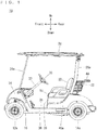
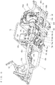
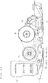
- the seat portion 18 extends in a width direction of the golf car 10 at a more rearward position than the pair of front wheels 12a, 12b, but at a more forward position than the pair of rear wheels 14a, 14b.
- the seat portion 18 is supported by a seat rail 72 (which will be described later) of the frame portion 16.
- a seat back 20 is provided at an obliquely upward and rearward position of the seat portion 18.
- a basket 22 for accommodating baggage is provided behind the seat back 20.
- the seat back 20 and the basket 22 are supported by rear pillars 26a, 26b which will be described later.
- a pair of front pillars 24a, 24b are provided at more forward positions than the seat portion 18, whereas a pair of rear pillars 26a, 26b are provided at more rearward positions than the seat portion 18.
- the front pillars 24a, 24b and the rear pillars 26a, 26b are supported by the frame portion 16 at their lower end portions.
- the front pillars 24a, 24b and the rear pillars 26a, 26b extend from below to above, while tilting slightly rearward.
- a roof portion 28 covers above the seat portion 18, and is supported by the front pillars 24a, 24b and the rear pillars 26a, 26b.
- a steering wheel 30 is located ahead of the seat back 20.
- the steering wheel 30 is connected to the front wheels 12a, 12b via a steering shaft 32 and an unillustrated connection mechanism.
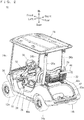
- the frame portion 16 is covered with a cowl 34, a pair of side protectors 36, a floor panel 38, a body panel 39, a pair of rear fender covers 40a, 40b and a rear floor cover 42, each made of a resin, for example.
- the cowl 34 covers the front region of the frame portion 16 and above the front wheels 12a, 12b.
- the pair of side protectors 36 cover an intermediate region of the frame portion 16 from two sides.
- the floor panel 38 which functions as a footrest for the driver and the passenger sitting on the seat portion 18 to rest their feet, provides a bottom portion of a cabin space of the golf car 10.
- the body panel 39 covers a front region below the seat portion 18.
- the pair of rear fender covers 40a, 40b cover two sides below the seat portion 18 and above the pair of rear wheels 14a, 14b.
- the rear floor cover 42 is sandwiched by rear end portions of the pair of rear fender covers 40a, 40b, and has a concave portion 42a for placement of golf bags, for example.
- CVT Continuous Variable Transmission
- a transmission 146 which will be described later.
- a holding portion 44 for holding the golf bags.
- the holding portion 44 is supported by connecting members 70a, 70b (which will be described later).
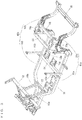
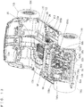
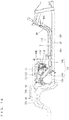
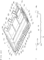
- the frame portion 16 includes a pair of main frames 46a, 46b which are spaced apart from each other in a width direction of the vehicle and extend in a fore-aft direction of the vehicle; cross members 52, 54, 56, 58, and a pair of support frames 60a, 60b.
- the pair of main frames 46a, 46b respectively include front frames 48a, 48b extending in the fore-aft direction; and rear frames 50a, 50b extending rearward from rear end portions of the respective front frames 48a, 48b.
- the pair of front frames 48a, 48b are formed so that their front end portions have a narrower space from each other than their rear end portions do.
- the pair of rear frames 50a, 50b are curved to project upward.
- the front frames 48a, 48b are connected to each other by the cross members 52, 54.
- a portion where the front frame 48a and the rear frame 50a are joined to each other and a portion where the front frame 48b and the rear frame 50b are joined to each other are connected to each other by the cross member 56.
- the rear frames 50a, 50b have their rear end portions connected to each other by the cross member 58.
- the main frames 46a, 46b are connected to each other by the cross members 52, 54, 56, 58 which extend in the vehicle's width direction.
- the cross members 52, 54, 56, 58 are spaced apart from each other in the vehicle's fore-aft direction, and are disposed in this order from the front to the rear of the vehicle.
- the cross member 52 is joined to the pair of support frames 60a, 60b which extend obliquely forward.
- the cross members 54, 56, 58 represent the first, the second and the third cross members respectively.
- connection frame 68 extends in the vehicle's width direction, with its two end portions extending downward, to provide an upward projecting substantially U shaped element.
- the connection frames 66 and 68 are spaced apart from each other in the vehicle's fore-aft direction, and are connected to each other by the connecting members 70a, 70b.
- the pair of support frames 64a, 64b have their upper end portions; the connection frame 66 have two side portions; and these portions are connected to each other by the seat rail 72.
- the seat rail 72 is formed substantially in a C shape extending in a horizontal direction.
- a pair of brackets 74a, 74b are attached side by side in the vehicle's width direction.
- a pair of engine brackets 76a, 76b are joined to the pair of brackets 74a, 74b.
- the engine brackets 76a, 76b are connected to each other via a cross member 78.
- the cross member 78 is joined to a support frame 79 which extends forward and support frames 80a, 80b which extend rearward.
- the support frame 79 has its tip portion formed with a projection 79a.
- the support frames 80a, 80b have their respective rear end portions formed with through-holes 82a, 82b (see Fig. 8 ) .
- On the cross member 78 and the support frames 80a, 80b there is attached an engine bracket 84 for supporting an engine 114 (which will be described later).
- the cross member 78 is joined to the engine brackets 76a, 76b pivotably in an up-down direction. Accordingly, the engine bracket 84 is also pivotable in the up-down direction.
- the cross member 56 is joined to a pair of frames 86a, 86b which extend rearward.
- the pair of frames 86a, 86b are connected to each other at regions near their rear end portions, by a cross member 88.
- the pair of frames 86a, 86b have their rear end portions joined to the cross member 58.
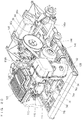
- the frame portion 16 supports an undercover 90.
- the undercover 90 has a front cover portion 92 and a rear cover portion 94 respectively on its forward and rearward sides.
- the front cover portion 92 is between the cross members 54 and 56, and is attached to the pair of front frames 48a and 48b, and to the cross members 54 and 56.
- the rear cover portion 94 is located between the cross members 56 and 58, and is attached to the cross members 56 and 88, the frames 86a, 86b, and the rear frames 50a, 50b.
- a pair of inner cowls 95 (the inner cowl on the right side is not shown) are attached respectively.
- the pair of inner cowls 95 are placed between the rear wheels 14a, 14b and the rear fender covers 40a, 40b to cover above the respective rear wheels 14a, 14b.
- the front cover portion 92 and the rear cover portion 94 of the undercover 90 will be described later.
- the undercover 90 On an under side, an upper side, a front side, a left side, a right side and a rear side of the engine room S, there are provided the undercover 90, the seat portion 18, the body panel 39, the heat insulation board 176 and the left inner cowl 95, the fuel tank 168 and the right inner cowl 95, and the rear floor cover 42 respectively.
- the undercover 90 namely the front cover portion 92 and the rear cover portion 94, are disposed at a lower place than the engine 114, and provide an under side of the engine room S.
- the panel main body 96 includes a first panel portion 102 extending substantially horizontally in the fore-aft direction between the front wheels 12a, 12b and the rear wheels 14a, 14b; a second panel portion 104 placed behind the front wheels 12a, 12b and extending upward from a front end region of the first panel portion 102; and third panel portions 106a, 106b extending rearward from left and right rear end regions of the first panel portion 102.
- the first panel portion 102 is located ahead of the engine room S; the third panel portion 106a is located on the left side of the engine room S; and the third panel portion 106b is located on the right side of the engine room S.
- a rectangular plate-like cover portion 110 which is supported by the frame portion 16, is provided ahead of the opening 98. Further, the groove portion 100 is covered by a lid portion 112 (see Fig. 8 ).
- the lid portion 112 is provided by a strip-like platy member formed to a longitudinal shape of the groove portion 100.
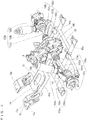
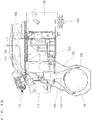
- the engine bracket 84 supports the engine 114.
- the engine 114 is an air-cooled engine which provides a single-cylinder, for example.
- the engine 114 provides a fuel injection device 115 which injects fuel into an air intake tube 126.
- the engine 114 is placed behind the first panel portion 102 of the floor panel 38, and includes a cylinder head 116, a cylinder body 118 and a crank case 120.
- the engine 114 is tilted forward.
- An air cleaner 122 is provided above the engine 114.
- the air cleaner 122 is joined to an air intake duct 124 via a joint 123.
- the air intake duct 124 is located on the right side of the air cleaner 122, and includes a cylindrical front duct 124a and a noise-reducing rear duct 124b of a flattened shape. A rear end portion of the front duct 124a and a front end portion of the rear duct 124b are joined to each other. In order to introduce the external air from the groove portion 100, the front duct 124a is disposed to face the groove portion 100 from the engine room S, and a rear end portion of the rear duct 124b is joined to the joint 123. Thus, the air intake duct 124 and the air cleaner 122 communicate with each other. As indicated by Arrow X in Fig.
- the external air which is introduced from ahead and comes through the opening 98 and into the groove portion 100, is then introduced into the air cleaner 122 from the groove portion 100 via the air intake duct 124. Then, after being cleaned by the air cleaner 122, the air is supplied, via the air intake tube 126, into the engine 114.
- the air cleaner 122 is provided between the air intake duct 124 and the engine 114.
- a muffler 128 is provided adjacently on a side (on the left side in the present embodiment) of the engine 114.
- the engine 114 and the muffler 128 are joined to each other via an exhaust pipe 130. Exhaust gas from the engine 114 is supplied to the muffler 128 via the exhaust pipe 130.
- the exhaust pipe 128a of the muffler 128 has a rear end portion, to which a joint exhaust 128b including an unillustrated silencer is attached (see Fig. 22 ).
- the cylinder body 118 of the engine 114 is covered by the shroud 132, with an air-flowable gap between the cylinder body 118 and the shroud 132.
- a fan case 134 is provided on a side surface (on the right side surface in the present embodiment) of the engine 114.
- the shroud 132 and the fan case 134 are connected to each other.
- Inside the fan case 134 there is provided a fan 136 for supplying the external air from the groove portion 100 into the shroud 132 (between the shroud 132 and the engine 114).
- the fan 136 is preferably connected to a crank shaft 142 (see Fig. 18 ) and driven thereby.
- the muffler 128 is covered by a muffler cover 138 so that an air-flowable gap is formed between the muffler 128 and the muffler cover 138.
- the muffler cover 138 is made of a resin for example, and is provided with an insulation member on its inner surface, and is formed to have a generally rectangular tubular upper portion and a generally cylindrical lower portion.
- the shroud 132 and the muffler cover 138 communicate with each other via a duct 139 which covers the exhaust pipe 130. It should be noted here that Fig. 11 , Fig. 12 , Fig. 20 and Fig. 21 do not show the duct 139. Referring to Fig.
- an exhaust duct 140 is connected to an exit end portion of the muffler cover 138.
- the exhaust duct 140 has its inner circumferential surface provided with sound absorbing members 140a, 140b made of glass wool for example.
- the sound absorbing members 140a, 140b are held on an inner circumferential surface of the exhaust duct 140 respectively by holding members 140c, 140d made of a punching metal for example.
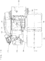
- the exhaust duct 140 has its rear end portion attached to an opening 92a of the front cover portion 92 and exposed to the outside from the opening 92a (see Fig. 7 , Fig. 20 and Fig. 22 ).
- the opening 92a is located at a more rearward position than the center of the front cover portion 92 in the fore-aft direction, and is located at a more rearward position than the muffler cover 138, in a side view. Also, in a side view, the opening 92a is located at a more rearward position than the muffler 128.
- the muffler cover 138 is supported by the support frame 79 (see Fig. 4 and Fig. 11 ), as the projection 79a of the support frame 79 is inserted through a hole 141a of a bracket 141 attached on a side surface of the muffler cover 138. As indicated by Arrow Y in Fig. 17 and Fig.
- the external air which is introduced into the shroud 132 by the fan 136 flows between the shroud 132 and the engine 114 (the cylinder body 118), into the muffler cover 138 (between the muffler cover 138 and the muffler 128), and serves as a cooling wind to cool the engine 114 and the muffler 128.
- the air inside the muffler cover 138 flows through the exhaust duct 140 and is discharged from the opening 92a of the front cover portion 92, to the outside, below the engine room S.
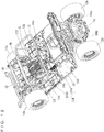
- an output from the crank shaft 142 of the engine 114 is transmitted via the CVT 144 to the transmission 146.
- the CVT 144 is located behind the muffler 128, whereas the transmission 146 is located behind the engine 114, between the pair of rear wheels 14a, 14b.
- the engine 114, the muffler 128, the shroud 132, the muffler cover 138, the exhaust duct 140, the CVT 144 and the transmission 146 described above are housed in the engine room S.
- the transmission 146 is joined to a pair of rotation transmission portions 148a, 148b.
- the rotation transmission portion 148a extends to the left of the transmission 146, and includes a constant-velocity joint 150a, a drive shaft 152a, a constant-velocity joint 154a and an axle 156a.
- the transmission 146 has its output shaft (not illustrated) connected to the drive shaft 152a by the constant-velocity joint 150a, whereas the drive shaft 152a and the axle 156a are connected to each other by the constant-velocity joint 154a.
- the rotation transmission portion 148b extends to the right of the transmission 146, and includes a constant-velocity joint 150b, a drive shaft 152b, a constant-velocity joint 154b and an axle 156b.
- the transmission 146 has its output shaft connected to the drive shaft 152b by the constant-velocity joint 150b, whereas the drive shaft 152b and the axle 156b are connected to each other by the constant-velocity joint 154b.
- the axle 156a supports the rear wheel 14a, whereas the axle 156b supports the rear wheel 14b.
- the through-hole 82a at the rear end portion of the support frame 80a is penetrated by the output shaft of the transmission 146 between the transmission 146 and the constant-velocity joint 150a
- the through-hole 82b at the rear end portion of the support frame 80b is penetrated by the output shaft of the transmission 146 between the transmission 146 and the constant-velocity joint 150b (see Fig. 13 ).
- the pair of rear wheels 14a, 14b are suspended by a pair of suspensions 158a, 158b.
- the pair of suspensions 158a, 158b are provided by independent suspension systems.
- the pair of suspensions 158a, 158b include knuckles 160a, 160b, arms 162a, 162b and shock absorbers 164a, 164b respectively.
- the knuckle 160a supports the axle 156a rotatably.
- the arm 162a connects a lower portion of the knuckle 160a and the frame 86a to each other.
- the shock absorber 164a has a lower end portion and an upper end portion, respectively joined to an upper end portion of the knuckle 160a and to the connection frame 68.
- the knuckle 160b supports the axle 156b rotatably.
- the arm 162b connects a lower portion of the knuckle 160b and the frame 86b to each other.
- the shock absorber 164b has a lower end portion and an upper end portion, respectively joined to an upper end portion of the knuckle 160b and to the connection frame 68.
- the pair of front wheels 12a, 12b are suspended by a pair of suspensions 166a, 166b attached to the front region of the frame portion 16.
- the pair of suspensions 166a, 166b are provided by independent suspension systems.
- the fuel tank 168 is placed on the right side of the engine 114 and on the third panel portion 106b of the floor panel 38. Between the engine 114 and the fuel tank 168, a sound absorbing member 170 is erected and attached to a side surface of the fuel tank 168. Also, a battery 172 is placed on the left of the muffler cover 138 and on the third panel portion 106a of the floor panel 38. Between the muffler cover 138 and the battery 172, a two-ply structure made of a sound absorbing member 174 and the heat insulation board 176 is erected. It is possible, with the sound absorbing members 170 and 174, to absorb noise from the engine room S, whereas it is possible, with the heat insulation board 176, to reduce heat to conduct from the engine room S to the battery 172.
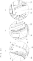
- the front cover portion 92 includes a cover portion main body 178.
- the cover portion main body 178 has its upper surface provided with a groove portion 180 to drain water.
- the groove portion 180 extends in the width direction (left and right) and in the fore-aft direction in a rear region of the cover portion main body 178.
- four water drainage holes 182a through 182d are formed at two side regions and rear end regions.
- the opening 92a is located at a rear left corner of the cover portion main body 178.
- four water drainage holes 184a through 184d are formed.
- three water drainage holes 186a through 186c are formed at a space in the width direction in a front end region of the cover portion main body 178.
- a brim-like portion 190 protrudes forward.
- brim-like portions 192a, 192b protrude laterally, respectively.
- the brim-like portion 190 is formed with two screw holes 194a, 194b.
- the brim-like portions 192a, 192b are formed with screws holes 196a, 196b respectively.
- the brim-like portions 190, 192a, 192b are formed with upward protruding rib-like portions 198a through 198e on their inner sides. Also, in the cover portion main body 178, two pawl portions 200a, 200b are provided at an intermediate position of its front end region.
- the groove portion 180 in an upper surface of the cover portion main body 178, it becomes easy to guide water to the holes 182a through 182d.
- the rib-like portions 198a through 198e it is possible to close gaps between the cover portion main body 178 (front cover portion 92) and the cross member 54, and between the cover portion main body 178 (front cover portion 92) and the front frames 48a, 48b.
- the rear cover portion 94 includes a cover portion main body 202.
- the cover portion main body 202 has its upper surface formed with holding portions 204a, 206a for holding the frame 86a; holding portions 204b, 206b for holding the frame 86b; and holding portions 208a, 208b for holding the cross member 88. Near the holding portions 204a, 206a, 204b, 206b, 208a, 208b, there are water drainage holes 210a, 210b, 210c, 210d, 210e, 210f respectively.
- the cover portion main body 202 is provided with storage portions 212a, 212b for storing rear end portions of the frames 86a, 86b.
- the storage portions 212a, 212b are formed with water drainage holes 214a, 214b (see Fig. 7 ) respectively. Also, three water drainage holes 216a through 216c are formed at a space in the width direction in a front end region of the cover portion main body 202. In the front end region of the cover portion main body 202, three pawl portions 218a through 218c extend obliquely in an upward and forward direction, forming upward convex curves at a space in the width direction. At rear ends of both side regions of the cover portion main body 202, screw holes 220a, 220b are formed.
- the pawl portions 188a through 188d at a rear end region of the front cover portion 92 are engaged with the cross member 56 from front.
- the front cover portion 92 is pivoted around the pawl portions 188a through 188d to bring the brim-like portion 190 into contact with the lower surface of the cross member 54, and bring the brim-like portions 192a, 192b into contact with the lower surfaces of the front frames 48a, 48b.
- the rib-like portions 198a through 198e make contact with side surfaces of the cross member 54 and of the front frames 48a, 48b.
- the pawl portions 200a, 200b engage with the bracket 74a from both sides in the width direction. Then, with fasteners 222 (see Fig. 7 ) such as bolts inserted through the holes 194a, 194b, the brim-like portion 190, which is at a front end region of the front cover portion 92, is fixed to the cross member 54. Also, with fasteners 224 (see Fig. 7 ) such as bolts inserted through the holes 196a, 196b, the brim-like portions 192a, 192b, which are at two side regions of the front cover portion 92, are fixed to the front frames 48a, 48b. Thus, the front cover portion 92 is fixed to the cross member 54 and the front frames 48a, 48b.
- the pawl portions 218a through 218c at a front end region of the rear cover portion 94 are engaged with the cross member 56 from rear.
- the rear cover portion 94 is pivoted around the pawl portions 218a through 218c to bring an upper end surface of the storage portions 212a, 212b into contact with the lower surface of the cross member 58.
- This process causes the holding portions 204a, 206a to hold the frame 86a, the holding portions 204b, 206b to hold the frame 86b, and the holding portions 208a, 208b to hold the cross member 88.
- fasteners 226 see Fig. 7
- the rear end region of the rear cover portion 92 is fixed to the rear frames 50a, 50b.
- the rear end region of the front cover portion 92 and the front end region of the rear cover portion 94 are engaged with the cross member 56; and thereafter, the front cover portion 92 is fixed to the cross member 54 and the front frames 48a, 48b, and the rear cover portion 94 is fixed to the rear frames 50a, 50b to complete the process, and therefore, it is easy to assemble the front cover portion 92 and the rear cover portion 94 to the frame portion 16.
- the rear end region of the front cover portion 92 and the front end region of the rear cover portion 94 are simply engaged with the cross member 56; and therefore, when disassembling, it is only required to unfix the front cover portion 92 from the cross member 54 and the front frames 48a, 48b, and unfix the rear cover portion 94 from the rear frames 50a, 50b. Then, the front cover portion 92 and the rear cover portion 94 are easily removed from the frame portion 16. As described, it is possible to attach/detach the undercover 90 easily.
- the undercover 90 is capable of absorbing impact from below, and reducing damage or the like to the undercover 90.
- Access to the engine room S from below is provided by simply removing the front cover portion 92. This makes it easy to perform activities such as maintenance procedures inside the engine room S.
- Exhaust gas from the muffler 128 passes through the exhaust duct 140 which is connected to the exit end portion of the muffler cover 138 and the opening 92a of the front cover portion 92, and then to the outside from below the engine room S. In this process, noise from the muffler 128 is attenuated in the exhaust duct 140. Since the exhaust duct 140 is connected to the muffler cover 138, noises propagating through the muffler cover 138, such as vibration noise of the engine 114, are attenuated inside the exhaust duct 140. Therefore, it is possible to reduce noise leakage to the outside of the vehicle.
- the exhaust duct 140 is attached to the opening 92a which is located at a more rearward position than the center of the front cover portion 92 in the fore-aft direction. This makes it easy to perform activities such as maintenance procedures inside the engine room S. Specifically, when the front cover portion 92 is unfixed from the cross member 54 and the front frames 48a, 48b; and the front end region of the front cover portion 92 is moved downward to open the front cover portion 92 while the rear end region of the front cover portion 92 is engaged with the cross member 56, an amount of positional change of the front cover portion 92 is smaller in its rear region than its front region.
- the opening 92a Since the opening 92a is located at a more rearward position than the center of the front cover portion 92 in the fore-aft direction, change in the position of the opening 92a is small if the front cover portion 92 is opened slightly. Thus, there is no need to remove the exhaust duct 140 from the opening 92a if maintenance procedures can be performed in this state.
- the opening 92a in the front cover portion 92 is not located beneath the muffler cover 138, but is located at a more rearward position than the muffler cover 138 in a side view, it is possible to allow the exhaust duct 140 to extend rearward to make the exhaust duct 140 relatively long. Therefore, it is possible to discharge the exhaust gas from below the engine room S toward the rear. Further, this allows further attenuation of the noises from the muffler 128 and the muffler cover 138 inside the exhaust duct 140, and makes it possible to further reduce the noise leakage out of the vehicle.
- the front cover portion 92 is fixed to the cross member 54 and the front frames 48a, 48b; and the rear cover portion 94 is fixed to the rear frames 50a, 50b.
- the invention is not limited to this.
- the present invention requires that the front cover portion 92 should be fixed by means of a fastener at least to the cross member 54 or to the front frames 48a, 48b, while the rear cover portion 94 should be fixed by means of a fastener at least to the cross member 58 or to the rear frames 50a, 50b.
- the front cover portion 92 is not fixed to the front frames 48a, 48b; the pawl portions 188a through 188d in the rear end region of the front cover portion 92 are engaged with the cross member 56; the front end region of the front cover portion 92 is fixed to the cross member 54; the rear cover portion 94 does not have the holding portions 204a, 206a, 204b, 206b, 208a, 208b; the pawl portions 218a, 218b, 218c in the front end region of the rear cover portion 94 are engaged with the cross member 56; and a rear end region of the rear cover portion 94 is fixed to the cross member 58 or to the rear frames 50a, 50b.
- the rear end region of the front cover portion 92 and the front end region of the rear cover portion 94 are simply engaged with the cross member 56; therefore, when disassembling, it is only required to unfix the front end region of the front cover portion 92 from the cross member 54 and unfix the rear end region of the rear cover portion 94 from the cross member 58 or the rear frame portions 50a, 50b. Then, the front cover portion 92 and the rear cover portion 94 are removed from the frame portion 16 more easily. As described, it is possible to attach/detach the undercover 90 more easily.
- the rear end region of the front cover portion 92 and the front end region of the rear cover portion 94 are simply engaged with the cross member 56; and therefore, in a case of impact from below, the front cover portion 92 pivots upward around its front end region, whereas the rear cover portion 94 pivots upward around its rear end region, to absorb the impact easily.
- the undercover 90 is capable of absorbing easily impact from below, and further reducing damage or the like to the undercover 90.
- the rear cover portion 94 may be formed with a water drainage groove portion in its upper surface.
- pawl portions 228a, 228b are provided in the front end region of the cover portion main body 178 of the front cover portion 92 as shown in Fig. 23
- pawl portions 230a, 230b are provided in a rear end region of the cover portion main body 202 of the rear cover portion 94 as shown in Fig. 24 .
- the pawl portions 188a through 188d of the rear end region of the front cover portion 92 and the pawl portions 218a through 218c of the front end region of the rear cover portion 94 are engaged with the cross member 56; and thereafter, the pawl portions 228a, 228b of the front end region of the front cover portion 92 are engaged with the cross member 54 and the pawl portions 230a, 230b of the rear end region of the rear cover portion 94 are engaged with the cross member 58.
Landscapes
- Engineering & Computer Science (AREA)
- Chemical & Material Sciences (AREA)
- Combustion & Propulsion (AREA)
- Mechanical Engineering (AREA)
- Transportation (AREA)
- General Engineering & Computer Science (AREA)
- Body Structure For Vehicles (AREA)
Applications Claiming Priority (2)
| Application Number | Priority Date | Filing Date | Title |
|---|---|---|---|
| JP2016136458A JP6276334B2 (ja) | 2016-07-08 | 2016-07-08 | 車両 |
| PCT/JP2017/020506 WO2018008305A1 (ja) | 2016-07-08 | 2017-06-01 | 車両 |
Publications (3)
| Publication Number | Publication Date |
|---|---|
| EP3483045A1 true EP3483045A1 (de) | 2019-05-15 |
| EP3483045A4 EP3483045A4 (de) | 2020-04-15 |
| EP3483045B1 EP3483045B1 (de) | 2024-07-31 |
Family
ID=60912656
Family Applications (1)
| Application Number | Title | Priority Date | Filing Date |
|---|---|---|---|
| EP17823912.5A Active EP3483045B1 (de) | 2016-07-08 | 2017-06-01 | Fahrzeug |
Country Status (6)
| Country | Link |
|---|---|
| US (1) | US10730566B2 (de) |
| EP (1) | EP3483045B1 (de) |
| JP (1) | JP6276334B2 (de) |
| AU (1) | AU2017292238B2 (de) |
| CA (1) | CA3020821C (de) |
| WO (1) | WO2018008305A1 (de) |
Families Citing this family (4)
| Publication number | Priority date | Publication date | Assignee | Title |
|---|---|---|---|---|
| US10780846B2 (en) * | 2018-12-21 | 2020-09-22 | Kawasaki Jukogyo Kabushiki Kaisha | Utility vehicle |
| US11767060B2 (en) * | 2019-04-12 | 2023-09-26 | Textron Innovations Inc. | Lightweight vehicle |
| JP7398356B2 (ja) * | 2020-10-20 | 2023-12-14 | 株式会社イノアックコーポレーション | 車両用アンダーカバー |
| WO2024258997A1 (en) * | 2023-06-12 | 2024-12-19 | Telo Trucks Inc. | Electric trucks and associated systems |
Family Cites Families (21)
| Publication number | Priority date | Publication date | Assignee | Title |
|---|---|---|---|---|
| JPS6027712Y2 (ja) * | 1977-03-17 | 1985-08-21 | 日野自動車株式会社 | 自動車用遮音カバ− |
| JPS53127419A (en) * | 1977-04-12 | 1978-11-07 | Chisso Corp | Dialkyl dichlorosilanes |
| JPS5522328A (en) * | 1978-08-07 | 1980-02-18 | Toshiba Corp | Sensitive liquid coating and equipment therefor |
| US4326445A (en) | 1980-03-19 | 1982-04-27 | Cadillac Gage Company | Armored underbody for road vehicle |
| JPS56152564A (en) * | 1981-03-10 | 1981-11-26 | Yoshiaki Nagaura | Manufacture of lens-shaped body and similar article thereof |
| JPH05171931A (ja) * | 1991-12-19 | 1993-07-09 | Honda Motor Co Ltd | 乗用車両のサイレンサ配置構造 |
| JPH0781440A (ja) * | 1993-09-09 | 1995-03-28 | Toyota Motor Corp | 車両のアンダーボデー構造 |
| DE19534972C2 (de) | 1995-09-14 | 2000-06-21 | Scania Cv Ab | Geräuschdämpfende Motorunterverkleidung |
| JP3333927B2 (ja) | 1997-09-09 | 2002-10-15 | 日産車体株式会社 | 車体の底部構造 |
| JPH11348833A (ja) * | 1998-06-09 | 1999-12-21 | Fuji Heavy Ind Ltd | 車両用アンダーカバーの取付構造 |
| JP2002366160A (ja) * | 2001-06-08 | 2002-12-20 | Toyota Motor Corp | アンダカバー |
| DE10130358A1 (de) * | 2001-06-23 | 2003-01-09 | Porsche Ag | Verkleidungsvorrichtung für die Unterseite eines Kraftfahrzeugs und Kraftfahrzeug |
| JP2005007995A (ja) * | 2003-06-18 | 2005-01-13 | Yamaha Motor Co Ltd | 小型車両 |
| JP4627459B2 (ja) * | 2005-06-23 | 2011-02-09 | 本田技研工業株式会社 | 車両前部構造 |
| JP4602389B2 (ja) * | 2007-10-19 | 2010-12-22 | 本田技研工業株式会社 | 車両用アンダーカバー |
| US7950486B2 (en) * | 2008-06-06 | 2011-05-31 | Polaris Industries Inc. | Vehicle |
| JP2010095105A (ja) | 2008-10-15 | 2010-04-30 | Yanmar Co Ltd | 多目的車両 |
| DE102012022108A1 (de) | 2012-11-13 | 2013-05-23 | Daimler Ag | Fahrzeug |
| JP6133663B2 (ja) * | 2013-03-29 | 2017-05-24 | 本田技研工業株式会社 | 鞍乗型車両のアンダーカバー構造 |
| US9333846B2 (en) | 2013-11-06 | 2016-05-10 | Kawasaki Jukogyo Kabushiki Kaisha | Utility vehicle |
| DE102016115753B8 (de) * | 2016-08-25 | 2023-06-22 | Dr. Ing. H.C. F. Porsche Aktiengesellschaft | Klappbare Unterbodenverkleidung |
-
2016
- 2016-07-08 JP JP2016136458A patent/JP6276334B2/ja active Active
-
2017
- 2017-06-01 CA CA3020821A patent/CA3020821C/en active Active
- 2017-06-01 EP EP17823912.5A patent/EP3483045B1/de active Active
- 2017-06-01 AU AU2017292238A patent/AU2017292238B2/en active Active
- 2017-06-01 US US16/092,368 patent/US10730566B2/en active Active
- 2017-06-01 WO PCT/JP2017/020506 patent/WO2018008305A1/ja not_active Ceased
Also Published As
| Publication number | Publication date |
|---|---|
| JP6276334B2 (ja) | 2018-02-07 |
| AU2017292238A1 (en) | 2018-11-15 |
| WO2018008305A1 (ja) | 2018-01-11 |
| CA3020821A1 (en) | 2018-01-11 |
| AU2017292238A8 (en) | 2019-07-11 |
| JP2018002124A (ja) | 2018-01-11 |
| CA3020821C (en) | 2019-12-31 |
| EP3483045A4 (de) | 2020-04-15 |
| US20190126992A1 (en) | 2019-05-02 |
| AU2017292238B2 (en) | 2019-07-11 |
| EP3483045B1 (de) | 2024-07-31 |
| US10730566B2 (en) | 2020-08-04 |
Similar Documents
| Publication | Publication Date | Title |
|---|---|---|
| CN110087930B (zh) | 用于多用途车辆的进气系统 | |
| EP3483045B1 (de) | Fahrzeug | |
| US20080289896A1 (en) | Four wheeled utility vehicle | |
| JP2007276703A (ja) | 作業用四輪車 | |
| AU2017292285B2 (en) | Vehicle | |
| CN105263787A (zh) | 多用途车辆 | |
| JP5926653B2 (ja) | 鞍乗り型車両の収納部構造 | |
| JP2008179340A (ja) | 自動二輪車 | |
| US10406903B2 (en) | Vehicle | |
| EP3482990B1 (de) | Fahrzeug | |
| JP2005029103A (ja) | 車両の車体構造 | |
| KR0123929B1 (ko) | 차량의 시이트장착구조 | |
| JPH1086679A (ja) | 車両のパワーユニット支持構造 | |
| CA2415114C (en) | Snowmobile exhaust system | |
| JP2016222020A (ja) | 作業車 | |
| WO2016189942A1 (ja) | 作業車 | |
| JPH06144019A (ja) | 車両の駆動系配設構造 | |
| JPH05262143A (ja) | エンジンルーム内への外気導入構造 |
Legal Events
| Date | Code | Title | Description |
|---|---|---|---|
| STAA | Information on the status of an ep patent application or granted ep patent |
Free format text: STATUS: THE INTERNATIONAL PUBLICATION HAS BEEN MADE |
|
| PUAI | Public reference made under article 153(3) epc to a published international application that has entered the european phase |
Free format text: ORIGINAL CODE: 0009012 |
|
| STAA | Information on the status of an ep patent application or granted ep patent |
Free format text: STATUS: REQUEST FOR EXAMINATION WAS MADE |
|
| 17P | Request for examination filed |
Effective date: 20181129 |
|
| AK | Designated contracting states |
Kind code of ref document: A1 Designated state(s): AL AT BE BG CH CY CZ DE DK EE ES FI FR GB GR HR HU IE IS IT LI LT LU LV MC MK MT NL NO PL PT RO RS SE SI SK SM TR |
|
| AX | Request for extension of the european patent |
Extension state: BA ME |
|
| DAV | Request for validation of the european patent (deleted) | ||
| DAX | Request for extension of the european patent (deleted) | ||
| A4 | Supplementary search report drawn up and despatched |
Effective date: 20200312 |
|
| RIC1 | Information provided on ipc code assigned before grant |
Ipc: B62D 21/02 20060101ALI20200306BHEP Ipc: B62D 21/03 20060101ALI20200306BHEP Ipc: B62D 25/20 20060101AFI20200306BHEP Ipc: F01N 13/08 20100101ALI20200306BHEP |
|
| STAA | Information on the status of an ep patent application or granted ep patent |
Free format text: STATUS: EXAMINATION IS IN PROGRESS |
|
| 17Q | First examination report despatched |
Effective date: 20201203 |
|
| GRAP | Despatch of communication of intention to grant a patent |
Free format text: ORIGINAL CODE: EPIDOSNIGR1 |
|
| STAA | Information on the status of an ep patent application or granted ep patent |
Free format text: STATUS: GRANT OF PATENT IS INTENDED |
|
| INTG | Intention to grant announced |
Effective date: 20231011 |
|
| GRAJ | Information related to disapproval of communication of intention to grant by the applicant or resumption of examination proceedings by the epo deleted |
Free format text: ORIGINAL CODE: EPIDOSDIGR1 |
|
| STAA | Information on the status of an ep patent application or granted ep patent |
Free format text: STATUS: EXAMINATION IS IN PROGRESS |
|
| INTC | Intention to grant announced (deleted) | ||
| GRAP | Despatch of communication of intention to grant a patent |
Free format text: ORIGINAL CODE: EPIDOSNIGR1 |
|
| STAA | Information on the status of an ep patent application or granted ep patent |
Free format text: STATUS: GRANT OF PATENT IS INTENDED |
|
| INTG | Intention to grant announced |
Effective date: 20240213 |
|
| GRAS | Grant fee paid |
Free format text: ORIGINAL CODE: EPIDOSNIGR3 |
|
| GRAA | (expected) grant |
Free format text: ORIGINAL CODE: 0009210 |
|
| STAA | Information on the status of an ep patent application or granted ep patent |
Free format text: STATUS: THE PATENT HAS BEEN GRANTED |
|
| AK | Designated contracting states |
Kind code of ref document: B1 Designated state(s): AL AT BE BG CH CY CZ DE DK EE ES FI FR GB GR HR HU IE IS IT LI LT LU LV MC MK MT NL NO PL PT RO RS SE SI SK SM TR |
|
| REG | Reference to a national code |
Ref country code: CH Ref legal event code: EP Ref country code: GB Ref legal event code: FG4D |
|
| REG | Reference to a national code |
Ref country code: DE Ref legal event code: R096 Ref document number: 602017083736 Country of ref document: DE |
|
| REG | Reference to a national code |
Ref country code: IE Ref legal event code: FG4D |
|
| REG | Reference to a national code |
Ref country code: LT Ref legal event code: MG9D |
|
| REG | Reference to a national code |
Ref country code: NL Ref legal event code: MP Effective date: 20240731 |
|
| PG25 | Lapsed in a contracting state [announced via postgrant information from national office to epo] |
Ref country code: PT Free format text: LAPSE BECAUSE OF FAILURE TO SUBMIT A TRANSLATION OF THE DESCRIPTION OR TO PAY THE FEE WITHIN THE PRESCRIBED TIME-LIMIT Effective date: 20241202 |
|
| REG | Reference to a national code |
Ref country code: AT Ref legal event code: MK05 Ref document number: 1708222 Country of ref document: AT Kind code of ref document: T Effective date: 20240731 |
|
| PG25 | Lapsed in a contracting state [announced via postgrant information from national office to epo] |
Ref country code: PT Free format text: LAPSE BECAUSE OF FAILURE TO SUBMIT A TRANSLATION OF THE DESCRIPTION OR TO PAY THE FEE WITHIN THE PRESCRIBED TIME-LIMIT Effective date: 20241202 |
|
| PG25 | Lapsed in a contracting state [announced via postgrant information from national office to epo] |
Ref country code: NO Free format text: LAPSE BECAUSE OF FAILURE TO SUBMIT A TRANSLATION OF THE DESCRIPTION OR TO PAY THE FEE WITHIN THE PRESCRIBED TIME-LIMIT Effective date: 20241031 |
|
| PG25 | Lapsed in a contracting state [announced via postgrant information from national office to epo] |
Ref country code: NL Free format text: LAPSE BECAUSE OF FAILURE TO SUBMIT A TRANSLATION OF THE DESCRIPTION OR TO PAY THE FEE WITHIN THE PRESCRIBED TIME-LIMIT Effective date: 20240731 Ref country code: PL Free format text: LAPSE BECAUSE OF FAILURE TO SUBMIT A TRANSLATION OF THE DESCRIPTION OR TO PAY THE FEE WITHIN THE PRESCRIBED TIME-LIMIT Effective date: 20240731 Ref country code: GR Free format text: LAPSE BECAUSE OF FAILURE TO SUBMIT A TRANSLATION OF THE DESCRIPTION OR TO PAY THE FEE WITHIN THE PRESCRIBED TIME-LIMIT Effective date: 20241101 Ref country code: FI Free format text: LAPSE BECAUSE OF FAILURE TO SUBMIT A TRANSLATION OF THE DESCRIPTION OR TO PAY THE FEE WITHIN THE PRESCRIBED TIME-LIMIT Effective date: 20240731 |
|
| PG25 | Lapsed in a contracting state [announced via postgrant information from national office to epo] |
Ref country code: BG Free format text: LAPSE BECAUSE OF FAILURE TO SUBMIT A TRANSLATION OF THE DESCRIPTION OR TO PAY THE FEE WITHIN THE PRESCRIBED TIME-LIMIT Effective date: 20240731 |
|
| PG25 | Lapsed in a contracting state [announced via postgrant information from national office to epo] |
Ref country code: LV Free format text: LAPSE BECAUSE OF FAILURE TO SUBMIT A TRANSLATION OF THE DESCRIPTION OR TO PAY THE FEE WITHIN THE PRESCRIBED TIME-LIMIT Effective date: 20240731 |
|
| PG25 | Lapsed in a contracting state [announced via postgrant information from national office to epo] |
Ref country code: IS Free format text: LAPSE BECAUSE OF FAILURE TO SUBMIT A TRANSLATION OF THE DESCRIPTION OR TO PAY THE FEE WITHIN THE PRESCRIBED TIME-LIMIT Effective date: 20241130 Ref country code: AT Free format text: LAPSE BECAUSE OF FAILURE TO SUBMIT A TRANSLATION OF THE DESCRIPTION OR TO PAY THE FEE WITHIN THE PRESCRIBED TIME-LIMIT Effective date: 20240731 |
|
| PG25 | Lapsed in a contracting state [announced via postgrant information from national office to epo] |
Ref country code: HR Free format text: LAPSE BECAUSE OF FAILURE TO SUBMIT A TRANSLATION OF THE DESCRIPTION OR TO PAY THE FEE WITHIN THE PRESCRIBED TIME-LIMIT Effective date: 20240731 |
|
| PG25 | Lapsed in a contracting state [announced via postgrant information from national office to epo] |
Ref country code: ES Free format text: LAPSE BECAUSE OF FAILURE TO SUBMIT A TRANSLATION OF THE DESCRIPTION OR TO PAY THE FEE WITHIN THE PRESCRIBED TIME-LIMIT Effective date: 20240731 Ref country code: RS Free format text: LAPSE BECAUSE OF FAILURE TO SUBMIT A TRANSLATION OF THE DESCRIPTION OR TO PAY THE FEE WITHIN THE PRESCRIBED TIME-LIMIT Effective date: 20241031 |
|
| PG25 | Lapsed in a contracting state [announced via postgrant information from national office to epo] |
Ref country code: RS Free format text: LAPSE BECAUSE OF FAILURE TO SUBMIT A TRANSLATION OF THE DESCRIPTION OR TO PAY THE FEE WITHIN THE PRESCRIBED TIME-LIMIT Effective date: 20241031 Ref country code: PL Free format text: LAPSE BECAUSE OF FAILURE TO SUBMIT A TRANSLATION OF THE DESCRIPTION OR TO PAY THE FEE WITHIN THE PRESCRIBED TIME-LIMIT Effective date: 20240731 Ref country code: NO Free format text: LAPSE BECAUSE OF FAILURE TO SUBMIT A TRANSLATION OF THE DESCRIPTION OR TO PAY THE FEE WITHIN THE PRESCRIBED TIME-LIMIT Effective date: 20241031 Ref country code: NL Free format text: LAPSE BECAUSE OF FAILURE TO SUBMIT A TRANSLATION OF THE DESCRIPTION OR TO PAY THE FEE WITHIN THE PRESCRIBED TIME-LIMIT Effective date: 20240731 Ref country code: LV Free format text: LAPSE BECAUSE OF FAILURE TO SUBMIT A TRANSLATION OF THE DESCRIPTION OR TO PAY THE FEE WITHIN THE PRESCRIBED TIME-LIMIT Effective date: 20240731 Ref country code: IS Free format text: LAPSE BECAUSE OF FAILURE TO SUBMIT A TRANSLATION OF THE DESCRIPTION OR TO PAY THE FEE WITHIN THE PRESCRIBED TIME-LIMIT Effective date: 20241130 Ref country code: HR Free format text: LAPSE BECAUSE OF FAILURE TO SUBMIT A TRANSLATION OF THE DESCRIPTION OR TO PAY THE FEE WITHIN THE PRESCRIBED TIME-LIMIT Effective date: 20240731 Ref country code: GR Free format text: LAPSE BECAUSE OF FAILURE TO SUBMIT A TRANSLATION OF THE DESCRIPTION OR TO PAY THE FEE WITHIN THE PRESCRIBED TIME-LIMIT Effective date: 20241101 Ref country code: FI Free format text: LAPSE BECAUSE OF FAILURE TO SUBMIT A TRANSLATION OF THE DESCRIPTION OR TO PAY THE FEE WITHIN THE PRESCRIBED TIME-LIMIT Effective date: 20240731 Ref country code: ES Free format text: LAPSE BECAUSE OF FAILURE TO SUBMIT A TRANSLATION OF THE DESCRIPTION OR TO PAY THE FEE WITHIN THE PRESCRIBED TIME-LIMIT Effective date: 20240731 Ref country code: BG Free format text: LAPSE BECAUSE OF FAILURE TO SUBMIT A TRANSLATION OF THE DESCRIPTION OR TO PAY THE FEE WITHIN THE PRESCRIBED TIME-LIMIT Effective date: 20240731 Ref country code: AT Free format text: LAPSE BECAUSE OF FAILURE TO SUBMIT A TRANSLATION OF THE DESCRIPTION OR TO PAY THE FEE WITHIN THE PRESCRIBED TIME-LIMIT Effective date: 20240731 |
|
| PG25 | Lapsed in a contracting state [announced via postgrant information from national office to epo] |
Ref country code: SM Free format text: LAPSE BECAUSE OF FAILURE TO SUBMIT A TRANSLATION OF THE DESCRIPTION OR TO PAY THE FEE WITHIN THE PRESCRIBED TIME-LIMIT Effective date: 20240731 Ref country code: RO Free format text: LAPSE BECAUSE OF FAILURE TO SUBMIT A TRANSLATION OF THE DESCRIPTION OR TO PAY THE FEE WITHIN THE PRESCRIBED TIME-LIMIT Effective date: 20240731 Ref country code: DK Free format text: LAPSE BECAUSE OF FAILURE TO SUBMIT A TRANSLATION OF THE DESCRIPTION OR TO PAY THE FEE WITHIN THE PRESCRIBED TIME-LIMIT Effective date: 20240731 |
|
| PG25 | Lapsed in a contracting state [announced via postgrant information from national office to epo] |
Ref country code: EE Free format text: LAPSE BECAUSE OF FAILURE TO SUBMIT A TRANSLATION OF THE DESCRIPTION OR TO PAY THE FEE WITHIN THE PRESCRIBED TIME-LIMIT Effective date: 20240731 |
|
| PG25 | Lapsed in a contracting state [announced via postgrant information from national office to epo] |
Ref country code: CZ Free format text: LAPSE BECAUSE OF FAILURE TO SUBMIT A TRANSLATION OF THE DESCRIPTION OR TO PAY THE FEE WITHIN THE PRESCRIBED TIME-LIMIT Effective date: 20240731 |
|
| PG25 | Lapsed in a contracting state [announced via postgrant information from national office to epo] |
Ref country code: IT Free format text: LAPSE BECAUSE OF FAILURE TO SUBMIT A TRANSLATION OF THE DESCRIPTION OR TO PAY THE FEE WITHIN THE PRESCRIBED TIME-LIMIT Effective date: 20240731 Ref country code: SK Free format text: LAPSE BECAUSE OF FAILURE TO SUBMIT A TRANSLATION OF THE DESCRIPTION OR TO PAY THE FEE WITHIN THE PRESCRIBED TIME-LIMIT Effective date: 20240731 |
|
| REG | Reference to a national code |
Ref country code: DE Ref legal event code: R097 Ref document number: 602017083736 Country of ref document: DE |
|
| PLBE | No opposition filed within time limit |
Free format text: ORIGINAL CODE: 0009261 |
|
| STAA | Information on the status of an ep patent application or granted ep patent |
Free format text: STATUS: NO OPPOSITION FILED WITHIN TIME LIMIT |
|
| 26N | No opposition filed |
Effective date: 20250501 |
|
| PGFP | Annual fee paid to national office [announced via postgrant information from national office to epo] |
Ref country code: GB Payment date: 20250618 Year of fee payment: 9 |
|
| PG25 | Lapsed in a contracting state [announced via postgrant information from national office to epo] |
Ref country code: SE Free format text: LAPSE BECAUSE OF FAILURE TO SUBMIT A TRANSLATION OF THE DESCRIPTION OR TO PAY THE FEE WITHIN THE PRESCRIBED TIME-LIMIT Effective date: 20240731 |