EP3482939B1 - Siebbereitstellungssystem - Google Patents
Siebbereitstellungssystem Download PDFInfo
- Publication number
- EP3482939B1 EP3482939B1 EP17201059.7A EP17201059A EP3482939B1 EP 3482939 B1 EP3482939 B1 EP 3482939B1 EP 17201059 A EP17201059 A EP 17201059A EP 3482939 B1 EP3482939 B1 EP 3482939B1
- Authority
- EP
- European Patent Office
- Prior art keywords
- screen
- printing
- station
- providing system
- magazine
- Prior art date
- Legal status (The legal status is an assumption and is not a legal conclusion. Google has not performed a legal analysis and makes no representation as to the accuracy of the status listed.)
- Active
Links
- 238000007639 printing Methods 0.000 claims description 211
- 230000003750 conditioning effect Effects 0.000 claims description 15
- 238000004140 cleaning Methods 0.000 claims description 8
- 238000003860 storage Methods 0.000 claims description 7
- 238000001035 drying Methods 0.000 claims description 4
- 238000001816 cooling Methods 0.000 claims description 3
- 238000010438 heat treatment Methods 0.000 claims description 3
- 239000000463 material Substances 0.000 description 23
- 238000002360 preparation method Methods 0.000 description 19
- 238000000034 method Methods 0.000 description 15
- 230000008569 process Effects 0.000 description 15
- 239000000758 substrate Substances 0.000 description 8
- 150000001875 compounds Chemical class 0.000 description 7
- 230000008901 benefit Effects 0.000 description 6
- 238000011161 development Methods 0.000 description 3
- 230000018109 developmental process Effects 0.000 description 3
- 238000007650 screen-printing Methods 0.000 description 3
- 230000006870 function Effects 0.000 description 2
- 238000004519 manufacturing process Methods 0.000 description 2
- 239000000203 mixture Substances 0.000 description 2
- 238000012545 processing Methods 0.000 description 2
- 238000010146 3D printing Methods 0.000 description 1
- 230000002411 adverse Effects 0.000 description 1
- 230000032683 aging Effects 0.000 description 1
- 239000000956 alloy Substances 0.000 description 1
- 229910045601 alloy Inorganic materials 0.000 description 1
- 239000012620 biological material Substances 0.000 description 1
- 239000000919 ceramic Substances 0.000 description 1
- 230000008859 change Effects 0.000 description 1
- 239000012459 cleaning agent Substances 0.000 description 1
- 239000002131 composite material Substances 0.000 description 1
- 230000001143 conditioned effect Effects 0.000 description 1
- 239000004020 conductor Substances 0.000 description 1
- 238000013461 design Methods 0.000 description 1
- 238000001514 detection method Methods 0.000 description 1
- 238000000605 extraction Methods 0.000 description 1
- 230000009969 flowable effect Effects 0.000 description 1
- 238000012423 maintenance Methods 0.000 description 1
- 230000007246 mechanism Effects 0.000 description 1
- 239000002184 metal Substances 0.000 description 1
- 229910052751 metal Inorganic materials 0.000 description 1
- 150000002739 metals Chemical class 0.000 description 1
- 229920000642 polymer Polymers 0.000 description 1
- 238000012805 post-processing Methods 0.000 description 1
- 238000002203 pretreatment Methods 0.000 description 1
- 239000007921 spray Substances 0.000 description 1
Images
Classifications
-
- B—PERFORMING OPERATIONS; TRANSPORTING
- B41—PRINTING; LINING MACHINES; TYPEWRITERS; STAMPS
- B41F—PRINTING MACHINES OR PRESSES
- B41F15/00—Screen printers
- B41F15/14—Details
- B41F15/34—Screens, Frames; Holders therefor
- B41F15/36—Screens, Frames; Holders therefor flat
-
- B—PERFORMING OPERATIONS; TRANSPORTING
- B41—PRINTING; LINING MACHINES; TYPEWRITERS; STAMPS
- B41F—PRINTING MACHINES OR PRESSES
- B41F15/00—Screen printers
- B41F15/08—Machines
-
- B—PERFORMING OPERATIONS; TRANSPORTING
- B41—PRINTING; LINING MACHINES; TYPEWRITERS; STAMPS
- B41F—PRINTING MACHINES OR PRESSES
- B41F15/00—Screen printers
- B41F15/08—Machines
- B41F15/0831—Machines for printing webs
- B41F15/0845—Machines for printing webs with flat screens
- B41F15/085—Machines for printing webs with flat screens with a stationary screen and a moving squeegee
-
- B—PERFORMING OPERATIONS; TRANSPORTING
- B41—PRINTING; LINING MACHINES; TYPEWRITERS; STAMPS
- B41P—INDEXING SCHEME RELATING TO PRINTING, LINING MACHINES, TYPEWRITERS, AND TO STAMPS
- B41P2227/00—Mounting or handling printing plates; Forming printing surfaces in situ
- B41P2227/50—Devices for storing printing plates
Definitions
- the invention relates to a screen preparation system, in particular for a printing device, in particular a 3D screen printing device, which has a screen holder for a printing screen and a doctor device assigned to the printing screen.
- Printing devices which use a doctor blade device and a printing screen, also referred to as a printing mask, to apply a material layer with a structure determined by the printing screen to a substrate are known from the prior art.
- a doctor blade device and a printing screen also referred to as a printing mask
- the use of the printing screen has the advantage that the structures can be applied multiple times to multiple substrates or to one substrate multiple times in a simple manner.
- the focus is on time and cost advantages.
- An alternative to this is to apply conductor track structures in a targeted manner by means of a spray nozzle, this being disadvantageous in terms of time and cost in comparison with the previously mentioned printing device.
- a disadvantage of screen printing devices is that different printing screens have to be used to produce different structures. This means an increased effort for the user because he has to replace the pressure screen, clean it and replace it with a new pressure screen that has to be refilled.
- document DE-A-26 43 226 discloses a screen delivery system according to the preamble of claim 1.
- the invention has for its object to provide a screen preparation system that reduces processing time, improves material utilization and ensures a safe printing process.
- the object on which the invention is based is achieved by the provision device having the features of claim 1.
- This has the advantage that a printing screen for a printing process, in particular for printing three-dimensionally shaped structures, is made available automatically, and furthermore preparatory and postprocessing steps are facilitated and in some cases completely avoided. This allows the throughput of the Printing device is increased and the load on the user is reduced, the printing result or the printing quality not being adversely affected thereby.
- the screen preparation system is characterized in that it has a transport device for transporting a pressure screen in each case, as well as at least one screen magazine which has a multiplicity of screen bearings for receiving a pressure screen in each case, and in particular at least one treatment station for treating the pressure screens, the transport device for this purpose is designed to operate the at least one sieve magazine and in particular the at least one treatment station with pressure sieves.
- the screen preparation system thus has a screen magazine for holding a large number of printing screens. This makes it possible to store a large number of identical and / or different printing screens in the screen magazine when they are not required for a printing process. This centralized storage ensures easy handling of a large number of printing screens.
- the printing screens preferably have markers, and the screen magazine has a detection device in order to detect the presence and position of printing screens in the screen magazine, so that the desired printing screen can be removed from the screen magazine in a simple manner if necessary.
- existing printing screens can in particular be pretreated or post-treated in order to make the printing process of a printing device efficient.
- the treatment station is designed to take over tasks that are otherwise incumbent on the user and thereby to simplify a printing process. Because the transport device reaches and operates both the treatment station and the screen magazine, the printing screens can be moved automatically from the screen magazine to the treatment station and vice versa by means of the transport device, so that the pre-treatment or post-treatment of a print screen takes place automatically.
- storage in the screen magazine has the advantage that it is not absolutely necessary to clean a printing screen after a printing process has been carried out. Instead, the printing screen is stored in the screen magazine with remnants of printing mass remaining on it until it is required again for a printing process with the same printing mass. This means that a cleaning step can also be dispensed with entirely.
- the screen preparation system has a screen use station that can be operated by the transport device with the printing screens.
- a screen usage station understood a station in which the sieve is used for its actual purpose. This means that the user does not have to remove a screen from the screen magazine himself and feed it to a printing device, for example. Rather, a printing screen is automatically made available to the user and / or a printing device.
- the sieve magazine is designed so that the user himself can remove a desired pressure sieve there.
- the screen magazine can be open on two sides, for example, the transport device having access to the printing screens on one side and the user on the other side.
- the screen use station is a screen removal station for the user.
- the user selected printing screen is thus made available to the user at the removal station, so that the user does not have to search for the suitable printing screen in the magazine himself.
- the removal station has a screen storage in which the transport device can place the selected printing screen for removal.
- the screen use station is a printing device.
- the transport device is thus designed to feed a selected printing screen directly to a printing device for carrying out a printing process.
- the transport device is designed to insert the selected printing screen into the screen holder of the printing device or to arrange it there, so that a printing process can subsequently be carried out automatically.
- the printing device is designed for printing three-dimensionally shaped structures, for which purpose the height of the print head and / or a printing table can be adjusted so that several layers of material can be produced by screen printing. Through an automated exchange of the printing screens, different three-dimensional structures are produced in a simple, fully automated manner.
- a plurality of screen magazines are present. This increases the number of print screens that can be stored and increases the variance in the production of, in particular, three-dimensional print structures. All screen magazines are expediently accessible by the transport device.
- At least one of the sieve magazines or the at least one sieve magazine has a conditioning device which is designed to create a climate in the sieve magazine generate and maintain, which prevents drying of printing mass remaining on a printing screen.
- the conditioning device ensures that printing screens that have been in the screen magazine for a long time and still have residues of printing material can be reused without first having to be cleaned and completely refilled with printing material. This reduces material consumption and shortens processing times.
- the conditioning device preferably has at least one air humidifier and / or dehumidifier, by means of which the air located in the sieve magazine can be moistened or dehumidified in order to set an optimal climate in the sieve magazine for the respective pressure mass.
- a plurality of sieve magazines can each have a conditioning device, the conditioning devices then being designed differently or identically, but can be operated differently. In this way it can be achieved that an optimal climate for the printing screens located there can be set in each screen magazine.
- printing screens that are used for printing with a first material are then stored in a first screen magazine, and printing screens that are used with a second material are stored in a second screen magazine, so that an optimal climate setting is possible.
- the conditioning device has at least one cooling device and / or heating device. This also helps to prevent drying out and to ensure that the remaining printing compound is reused on the printing screens regardless of the ambient conditions.
- at least one sieve magazine is divided into at least two sections which can be conditioned differently by the conditioning device. As a result, different climates can be set in a screen magazine, which are selected in particular as a function of different printing masses. Printing masses made of materials such as ceramics, metals, polymers, biomaterials, alloys, composite materials or other printable material combinations can be provided.
- At least one sieve magazine has at least one closing element, which can be displaced for releasing or closing a housing housing the sieve bearings.
- the sieve magazine thus has a housing that holds the sieve housed and is particularly completely closable by a closing element. This simplifies maintaining a climate or conditioning in the sieve magazine, since the set climate can be maintained longer.
- An actuator is expediently assigned to the closing element, which automates the closing or releasing of the screen bearing.
- the transport device is designed to actuate the closing element.
- At least one sieve magazine has at least one pushing device for advancing a selected pressure sieve from one of the sieve bearings.
- a pressure screen can be advanced from a screen store or a screen store by the sliding device, so that the screen can be more easily gripped by the transport device and brought to the screen removal station or the use station or to a treatment station.
- the sliding device is in particular designed to advance the printing screen to such an extent that it projects beyond the housing of the screen magazine.
- the housing has a removal opening, with which the closing element is assigned. The sliding device is assigned to the removal opening in such a way that it can advance a pressure screen associated with the removal opening from the removal opening on the housing, so that it can be gripped by the transport device.
- the height of the screen bearings in the screen magazine is preferably adjustable.
- a lifting device is preferably present in the sieve magazine, by means of which the sieve bearings can be raised or lowered in order to assign a selected pressure sieve to the removal opening or to assign an empty sieve bearing to the extraction opening so that it can be loaded with a pressure sieve.
- At least one treatment station is designed as a pressure screen cleaning station.
- the printing screen cleaning station preferably has cleaning agents, by means of which a printing screen can be completely cleaned of any pressure mass remaining thereon. If, for example, it is known that a certain printing screen no longer has to be used for a longer period of time and there is a risk that aging of the printing mass remaining on the printing screen is to be feared due to the long period of time, this will be the case Printing screen fed through the transport device to the screen cleaning station, cleaned and stored in the screen magazine.
- At least one treatment station is designed as a printing screen filling station, which serves to fill a printing screen with a desired pressure mass before the printing screen is fed to the printing device.
- a printing screen filling station serves to fill a printing screen with a desired pressure mass before the printing screen is fed to the printing device.
- the printing screen filling station has tanks for storing different materials for printing on the printing screens.
- An intermediate step, such as the manual filling of a printing screen can thus be dispensed with and a mechanism in the printing device itself, which otherwise carries out the filling of a printing screen, can be omitted, as a result of which the printing device is space-saving, compact and also inexpensive to implement.
- At least one treatment station is a control station.
- the control station is in particular designed to measure a printing screen and to compare a structure / pattern predetermined by the printing screen with a target pattern in order to detect damage to the printing screen. If damage is detected, the printing screen is no longer placed back in the screen magazine, but is taken out of service.
- the control station preferably has a camera device for recording the print pattern or the structure, and a memory in which the target patterns of the available print screens are stored, in order to easily damage and / or a condition of the respective print screen by comparison to capture.
- the invention relates to a screen magazine for storing printing screens for a printing device, which has at least one conditioning device for setting or maintaining a climate in the screen magazine, and in particular is designed as described above.
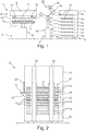
- Figure 1 shows a simplified side view of a printing system 1, which has a printing device 2, a screen magazine 3 and a transport device 4.
- the printing device 2 has a printing table 5 which can be adjusted in height by a lifting device 6, as indicated by a double arrow 7.
- a print head 8, which has a doctor device 9, is assigned to the printing table 5.
- the doctor blade device 9 has a screen holder 10, in which a printing screen 11 can be arranged.
- the screen receptacle 10 is designed, for example, as a plug-in receptacle into which the printing screen 11 can be inserted, in particular inserted laterally or horizontally, as in FIG Figure 1 shown.
- the screen holder 10 is designed so that the printing screen 11 can be inserted into it.
- the screen holder 10 optionally has controllable clamping elements 12, by means of which the printing screen 11 can be clamped in the screen holder 10, so that the orientation and position of the printing screen 11 do not change during a printing process in which the squeegee of the doctor device 9 is moved over the printing screen 11 changed.
- the sieve magazine 3 has a housing 13 and in the present case is arranged at a distance from the printing device 2.
- a plurality of sieve bearings 14 are arranged one above the other or stacked one above the other in the housing 13.
- the screen bearings 14 are designed, for example, like the screen holder 10 and optionally also have the clamping elements 12.
- a pressure screen 11 can be arranged in each screen store 14.
- the housing 13 is essentially closed, but has a removal opening 15 on a side facing the printing device 2, through which a pressure screen 11 can be taken into or out of the housing 13.
- the transport device 4 is designed to move the printing screens 11. According to the present exemplary embodiment, this has a multi-articulated transport arm 16 which carries a gripper 17 at its free end.
- the gripper 17 is, for example, designed to operate pneumatically or mechanically in order to grip a single pressure screen 11.
- the transport device 4 is arranged between the printing device 2 and the screen magazine 3 in such a way that the transport arm 16 can reach both a printing screen 11 assigned to the removal opening 15 and a printing screen 11 stored in the screen receptacle 10.
- the removal opening 15 extends almost over the entire height of the sieve magazine 3, the transport arm 16 being designed such that it can reach each sieve bearing 14 or the pressure sieve located therein.
- the transport device 4 is optionally equipped with its own lifting device 18 in order to increase the freedom of movement of the gripper 17. Together with the screen magazine 3, the transport device 4 forms a screen preparation system 25 for the printing device 2.
- the function of the advantageous printing system 1 is as follows.
- the transport device 4 is first activated to remove a specific printing screen 11 from the screen magazine 3 and to feed it to the screen holder 10.
- the printing screen 11 is locked in the screen holder 10 by means of the clamping means 12.
- the printing screen 11 is then acted upon by a printing compound, in particular printing paste, made of a selected material and a doctor blade of the doctor device 9 is pushed over the printing screen 11, so that the printing compound is printed through the printing screen 11 onto the printing table.
- the printing compound is applied directly to the printing table 5, or to a substrate 19 arranged on the printing table 5, which can be designed, for example, as a carrier substrate, or also as a printed circuit board, wafer or the like.
- the printing screen 11 has screen openings in some areas which correspond to the desired first layer of the structure to be printed. Many such structures can be incorporated into the printing screen 11, so that a plurality of components or structural elements / structures can also be produced side by side in one printing process on the substrate 19 and / or the printing table 5.
- the printing table 7 is moved downward, for example, by the lifting device 6 and a further printing operation is carried out, in which the same printing screen 11 is used to produce a further pressure position which has the same structure as the first pressure position .
- one of the other printing screens 11 is used instead of the same printing screen 11.
- the transport arm 16 moves the printing screen 11 located in the screen receptacle 10 into the screen magazine 3, namely into a screen storage 14 that is free there.
- the transport arm 16 then removes another screen 11 from another pressure bearing 14 and feeds it to the screen mounting 10 of the printing device 2 .
- a print position is then generated which differs in shape from the previous print position. With this principle you can several print layers are produced on top of each other, which differ from each other, whereby complex three-dimensional structures can also be produced.
- the printing table 5 is lowered a little, or alternatively the printing head 9 is raised a little.
- the screen bearings 14 are arranged fixedly in the housing 13, according to a further exemplary embodiment which is shown in Figure 2 is shown in a simplified representation, it is provided that the screen bearings 14 can be moved in height in the housing 13, as shown by a double arrow 20.
- the screen bearings 14 can be displaced along vertical rails 22 by means of a lifting device 21.
- the removal opening 15 of the housing 13 is arranged approximately in the center of the housing 13 and is narrow enough that only a pressure screen 11 can be removed from the housing 13 or inserted into the housing 13 by the transport arm 16.
- a specific printing screen 11 is to be removed from the screen magazine 3
- the screen bearings 14 are first moved or shifted vertically such that this printing screen 11 is assigned to the removal opening 15 and can be removed by the transport arm 16.
- the essentially closed design of the housing 13 of the screen magazine 3 has the advantage that there is a climate in the screen magazine 3 which improves the provision of the pressure screens 11 in the screen magazine 3.
- a conditioning device 23 is also arranged in the sieve magazine 3, which has, for example, a cooling device or heating device, an air humidifier and / or a dehumidifier in order to influence the climate in the sieve magazine 3.
- the climate is influenced in such a way that residues of the printing compound remaining on the respective printing screen 11 are kept flowable. This prevents drying out.
- the transport device 4 can be completely integrated into the printing device 2 or also completely into the sieve magazine 3.
- the transport device is partly formed by the printing device and partly by the sieve magazine 3.
- the sieve magazine 3 has, for example, a sliding device 24, as shown in FIG Figure 2 is shown by way of example.
- the sliding device 24 is arranged at the level of the removal opening 15 and serves to advance a sieve bearing 14 located at the level of the removal opening 15 with a pressure screen 11 or only the pressure screen 11 in the direction of the removal opening 15 to such an extent that the pressure screen 11 protrudes beyond the housing 13 and can thus be gripped particularly easily by the transport arm 16.
- the transport arm 16 is formed, for example, on the printing device 2.
- the removal opening can optionally be closed by a movable closing element 33.
- the sliding device 24 is designed such that it pushes the pressure screen completely through the removal opening 15 into the screen receptacle 10. If the removal opening 15 and sieve holder 10 are aligned with one another, this can be implemented simply and inexpensively.
- the printing device 2 then expediently has a corresponding sliding device which is designed to push the printing screen 11 back into the screen magazine and the screen bearing associated with the removal opening 15 after a printing process has been carried out.
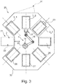
- FIG 3 shows a simplified plan view of advantageous screen preparation systems 25, of which in Figure 1 only the sieve magazine 3 and the transport device 4 are shown.
- the sieve preparation system 25 advantageously has 3 further, in the present case three further sieve magazines 3_1, 3_2 and 3_3.
- the screen preparation system 25 has a plurality of treatment stations 26, 27 and 28.
- the sieve magazines 3 and the treatment stations 26 to 28 are arranged in a circular ring around the transport device 4, so that a rondel of modules arranged next to one another is formed, the modules in particular extending along a circumference, in particular around the central axis 29 of the transport device 4 or the transport arm 16 spread evenly.
- the modules are housed together by a housing 30, which optionally has one or more maintenance doors 34 through which a user can obtain access to the screen preparation system 25. Between two neighboring modules, in this one In the case of the sieve magazine 3_1 and the treatment station 28, a sieve use station 31 is arranged, which can also be operated by the transport device 4.
- the screen use station 31 is designed as the printing device 2.
- the screen usage device can also be designed as a screen removal station 32, at which the user can be provided with a selected screen from one of the screen magazines 3_1 to 3_3 or 3 by the transport device 4, so that the user can manually select this selected printing screen 11 to a desired printing device or spends another use.
- a driving robot or a similar connection system can also be located at the screen usage station 31, by means of which a provided printing screen can be automatically supplied to a printing device or the like.
- the screen preparation system 25 can be used as a central screen preparation system in a printing hall with a large number of printing devices.
- the screen preparation system 25 can also be integrated into an in-line 3D printing line, in which case the screen use station 31 has, for example, the printing device 2, which then for automated transport of the carrier substrates into the printing device 2 and out of the printing device with three-dimensionally shaped structures thereon is trained.
- the treatment stations 26, 27 and 28 are in particular different treatment stations.
- the treatment station 26 is designed as a screen cleaning station. This is designed to clean a printing screen provided by the transport device 4 and thereby to remove all residues of printing material from the printing screen. After the cleaning has taken place, the affected printing screen is returned, for example, by the transport device 4 into one of the screen magazines 3 to 3_3.
- the treatment station 27 in the present case is a screen filling station which is designed to fill a printing screen fed to it with at least one material or a material of a printing material. This results in a centralized filling of the printing screens 11 by the screen filling station 27.
- the latter is designed to provide different printing compositions or materials, so that pre-filled printing screens with different printing compositions or printing materials can be provided by the screen preparation system 25.
- the transport device 4 ensures the transport of the respective Printing screen to the screen filling station 27 and from this, for example, to the screen use station 31.
- the screen filling station 27 can be supplied with cleaned printing screens as well as printing screens which have already been filled with a material and thus possibly have pressure residues.
- An identifier / identification feature arranged on the printing screens ensures that a material that is different from the previously applied material is received on a printing screen that has already been filled and has not previously been cleaned.
- the treatment station 28 in the present case is a control station which is in particular designed to measure a pressure screen 11 fed to it and to check it for damage. This can ensure that only properly designed and functioning printing screens are present in the printing screen preparation system 25 and are output by the screen use station 31.
- the treatment stations 26, 27 and 28 preferably each have a sieve bearing, on which the sieve bearing 14 corresponds or the sieve holder 10, for holding a pressure sieve in each case in order to carry out the respectively intended treatment.
- fewer treatment stations or even more treatment stations can be integrated in the printing screen preparation system 25.
- the number of printing stations and screen magazines 3 described here is only to be understood as an example. At least one sieve magazine and at least one treatment station are advantageously provided in order to form the advantageous printing sieve preparation system 25.
- one or more of the screen magazines 3, 3_1, 3_2 or 3_3, in the present case at least the screen magazine 3_3, are provided with the conditioning device 23 in order to condition the printing screens located there and to maintain the printing material thereon for later use.
Landscapes
- Engineering & Computer Science (AREA)
- Mechanical Engineering (AREA)
- Screen Printers (AREA)
- Electric Connection Of Electric Components To Printed Circuits (AREA)
Priority Applications (8)
| Application Number | Priority Date | Filing Date | Title |
|---|---|---|---|
| EP17201059.7A EP3482939B1 (de) | 2017-11-10 | 2017-11-10 | Siebbereitstellungssystem |
| JP2020544132A JP7319987B2 (ja) | 2017-11-10 | 2018-11-09 | スクリーン供給システム |
| PCT/EP2018/080796 WO2019092194A1 (de) | 2017-11-10 | 2018-11-09 | Siebbereitstellungssystem |
| SG11202004338YA SG11202004338YA (en) | 2017-11-10 | 2018-11-09 | Screen provision system |
| KR1020207016195A KR102635738B1 (ko) | 2017-11-10 | 2018-11-09 | 스크린 제공 시스템 |
| TW107139849A TW201932312A (zh) | 2017-11-10 | 2018-11-09 | 網版供應系統 |
| CN201880072740.2A CN111344149B (zh) | 2017-11-10 | 2018-11-09 | 丝网供应系统 |
| US16/762,251 US11801673B2 (en) | 2017-11-10 | 2018-11-09 | Screen provision system |
Applications Claiming Priority (1)
| Application Number | Priority Date | Filing Date | Title |
|---|---|---|---|
| EP17201059.7A EP3482939B1 (de) | 2017-11-10 | 2017-11-10 | Siebbereitstellungssystem |
Publications (2)
| Publication Number | Publication Date |
|---|---|
| EP3482939A1 EP3482939A1 (de) | 2019-05-15 |
| EP3482939B1 true EP3482939B1 (de) | 2020-05-20 |
Family
ID=60320700
Family Applications (1)
| Application Number | Title | Priority Date | Filing Date |
|---|---|---|---|
| EP17201059.7A Active EP3482939B1 (de) | 2017-11-10 | 2017-11-10 | Siebbereitstellungssystem |
Country Status (8)
| Country | Link |
|---|---|
| US (1) | US11801673B2 (ja) |
| EP (1) | EP3482939B1 (ja) |
| JP (1) | JP7319987B2 (ja) |
| KR (1) | KR102635738B1 (ja) |
| CN (1) | CN111344149B (ja) |
| SG (1) | SG11202004338YA (ja) |
| TW (1) | TW201932312A (ja) |
| WO (1) | WO2019092194A1 (ja) |
Families Citing this family (7)
| Publication number | Priority date | Publication date | Assignee | Title |
|---|---|---|---|---|
| EP3482935B1 (de) | 2017-11-10 | 2022-07-13 | Exentis Group AG | Siebeinheit für eine druckvorrichtung |
| EP3482939B1 (de) | 2017-11-10 | 2020-05-20 | Exentis Group AG | Siebbereitstellungssystem |
| DE102019123128B4 (de) * | 2019-08-28 | 2023-11-02 | S.A.S 3Dceram-Sinto | 3D-Siebdruckanlage und 3D-Siebdruckverfahren zur Herstellung eines Formkörpers |
| JP7478951B2 (ja) * | 2019-10-11 | 2024-05-08 | パナソニックIpマネジメント株式会社 | マガジン |
| GB201916469D0 (en) * | 2019-11-13 | 2019-12-25 | Asm Assembly Systems Singapore Pte Ltd | Screen loading system |
| WO2021112692A1 (en) * | 2019-12-04 | 2021-06-10 | University Of Canterbury | Method and apparatus for manufacturing an object |
| DE102022200764A1 (de) * | 2022-01-25 | 2023-07-27 | Siemens Energy Global GmbH & Co. KG | 3D-Siebdruck-Drucker und 3D-Siebdruckverfahren |
Family Cites Families (42)
| Publication number | Priority date | Publication date | Assignee | Title |
|---|---|---|---|---|
| US2610577A (en) * | 1948-10-05 | 1952-09-16 | Teximpex Ab | Screen printing machine |
| DE2643226C2 (de) * | 1976-09-25 | 1982-07-29 | Mathias 4815 Schloss Holte Mitter | Vorrichtung zum absatzweisen Bedrucken von Druckgut, insbesondere Warenbahnen mittels mehrerer bewegbarer ebener Schablonen |
| DE2722060C2 (de) * | 1977-05-16 | 1982-10-07 | Mathias 4815 Schloss Holte Mitter | Rahmen für ebene Siebschablonen zur übereinander gestapelten Anordnung mehrerer Schablonen in einer Siebdruckmaschine |
| DE2849872C2 (de) * | 1978-11-17 | 1982-05-13 | Mitter, Mathias, 4815 Schloss Holte | Vorrichtung zum Bedrucken von Warenbahnen mit ebener Siebdruckschablone |
| JPH01501052A (ja) | 1986-10-29 | 1989-04-13 | ホルデレッガー ユルグ | フラットで可撓性の印刷用スクリーンを含むスクリーン印刷装置 |
| JP2993260B2 (ja) * | 1992-02-24 | 1999-12-20 | 松下電器産業株式会社 | スクリーン印刷装置 |
| DE4226502C2 (de) | 1992-08-11 | 1995-01-05 | Kammann Maschf Werner | Rahmenanordnung für Siebdruckschablonen |
| JPH0671847A (ja) | 1992-08-31 | 1994-03-15 | Taiyo Yuden Co Ltd | スクリーン印刷機 |
| JP2783961B2 (ja) * | 1993-04-21 | 1998-08-06 | 日本無線株式会社 | クリーム半田印刷方法及び装置 |
| JP3288128B2 (ja) | 1993-05-21 | 2002-06-04 | 松下電器産業株式会社 | 印刷装置および印刷方法 |
| JPH07125175A (ja) * | 1993-11-08 | 1995-05-16 | Sanyo Electric Co Ltd | スクリーン印刷機 |
| EP0847682B1 (en) * | 1995-08-30 | 2004-05-19 | Matsushita Electric Industrial Co., Ltd. | Screen printing method and screen printing apparatus |
| US5694843A (en) | 1996-06-12 | 1997-12-09 | Chen; Tung-Chin | PC(printed circuit) board printing machine with cantilever-supported printing head and stencil holders and bi-directionally movable printing table |
| JPH1016185A (ja) * | 1996-07-03 | 1998-01-20 | Matsushita Electric Ind Co Ltd | スクリーン印刷方法及び装置 |
| JPH10171031A (ja) * | 1996-12-16 | 1998-06-26 | Fuji Photo Film Co Ltd | 複写装置 |
| US6152031A (en) * | 1999-02-10 | 2000-11-28 | Decruz; Rudolf R. | STS dayloader system |
| JP2000238233A (ja) | 1999-02-23 | 2000-09-05 | Fuji Mach Mfg Co Ltd | スクリーン検査方法,装置およびスクリーン印刷機 |
| DE19936572B4 (de) | 1999-08-03 | 2005-05-19 | Carl Zeiss Jena Gmbh | Klimaschrank |
| CH690645C1 (de) * | 1999-09-02 | 2002-08-30 | Liconic Ag | LAGERANLAGE UND LAGERBEHäLTNIS MIT LAGERANLAGE |
| EP1222245B1 (fr) * | 1999-10-19 | 2004-08-04 | Chim 92 | Composition nettoyante, procede pour nettoyer un ecran de serigraphie et dispositif de nettoyage |
| GB2360014A (en) | 2000-03-08 | 2001-09-12 | Dek Printing Machines Ltd | Screen printing device with movable screen and print head |
| EP1410908A4 (en) * | 2001-06-27 | 2011-10-05 | Berg Industry Co Ltd | ELECTROSTATIC PRESSURE DEVICE AND ELECTROSTATIC PRINTING METHOD |
| DE10344022B4 (de) | 2003-09-16 | 2006-07-13 | Thieme Gmbh & Co. Kg | Vorrichtung zum Siebdrucken |
| ES2242520B1 (es) | 2004-01-14 | 2007-02-16 | Comexi, S.A. | Dispositivo automatico de manipulacion y transporte de camisas de impresion. |
| CN1294009C (zh) * | 2004-06-29 | 2007-01-10 | 西北工业大学 | 多工位平面丝网印刷机 |
| JP2007098825A (ja) * | 2005-10-06 | 2007-04-19 | Noritsu Koki Co Ltd | 記録紙用マガジンおよびこれを備えたインクジェットプリンタ |
| DE102006061316B4 (de) * | 2006-12-22 | 2014-11-20 | Koenig & Bauer Aktiengesellschaft | Vorrichtung mit mehreren jeweils in einem Abstand zueinander angeordneten Speicherebenen |
| US8070473B2 (en) | 2008-01-08 | 2011-12-06 | Stratasys, Inc. | System for building three-dimensional objects containing embedded inserts, and method of use thereof |
| US8699177B2 (en) * | 2011-08-11 | 2014-04-15 | Spectra Logic Corporation | System for and method of properly positioning a magazine media adapted for library storage |
| US20140033886A1 (en) | 2012-08-01 | 2014-02-06 | Xerox Corporation | Document Production System and Method With Automated Die Exchange |
| JP5629298B2 (ja) | 2012-10-26 | 2014-11-19 | ヤマハ発動機株式会社 | 粘性材供給装置および粘性材印刷装置 |
| US9656289B2 (en) * | 2013-03-13 | 2017-05-23 | Nike, Inc. | Automatic painting on pliable items |
| DE202013004745U1 (de) | 2013-05-23 | 2014-08-26 | Exentis-Knowledge Ag | Anlage zur Herstellung von dreidimensionalen Siebdrucken |
| JP6221063B2 (ja) | 2014-03-17 | 2017-11-01 | パナソニックIpマネジメント株式会社 | スクリーン印刷装置及びスクリーン印刷方法 |
| WO2015175651A1 (en) | 2014-05-13 | 2015-11-19 | Massachusetts Institute Of Technology | Systems, devices, and methods for three-dimensional printing |
| WO2016095059A1 (de) | 2014-12-19 | 2016-06-23 | Hirschberg Engineering | Verfahren und vorrichtung zu schichtweisen aufbau von formkörpern |
| US11101391B2 (en) | 2015-07-22 | 2021-08-24 | Shin-Etsu Chemical Co., Ltd. | Screen printing apparatus, screen printing method, and electrode formation method of solar battery |
| US9559667B1 (en) * | 2015-08-21 | 2017-01-31 | International Business Machines Corporation | Oscillator phase noise using active device stacking |
| US11084278B2 (en) | 2016-11-24 | 2021-08-10 | Fuji Corporation | Screen printing machine having movable collection member for collecting viscous fluid |
| EP3482934B1 (de) | 2017-11-10 | 2021-06-30 | Exentis Group AG | 3d-siebdrucksystem zum drucken dreidimensional geformter strukturen |
| EP3482935B1 (de) | 2017-11-10 | 2022-07-13 | Exentis Group AG | Siebeinheit für eine druckvorrichtung |
| EP3482939B1 (de) | 2017-11-10 | 2020-05-20 | Exentis Group AG | Siebbereitstellungssystem |
-
2017
- 2017-11-10 EP EP17201059.7A patent/EP3482939B1/de active Active
-
2018
- 2018-11-09 TW TW107139849A patent/TW201932312A/zh unknown
- 2018-11-09 WO PCT/EP2018/080796 patent/WO2019092194A1/de active Application Filing
- 2018-11-09 US US16/762,251 patent/US11801673B2/en active Active
- 2018-11-09 SG SG11202004338YA patent/SG11202004338YA/en unknown
- 2018-11-09 KR KR1020207016195A patent/KR102635738B1/ko active IP Right Grant
- 2018-11-09 JP JP2020544132A patent/JP7319987B2/ja active Active
- 2018-11-09 CN CN201880072740.2A patent/CN111344149B/zh active Active
Non-Patent Citations (1)
| Title |
|---|
| None * |
Also Published As
| Publication number | Publication date |
|---|---|
| US11801673B2 (en) | 2023-10-31 |
| JP2021502283A (ja) | 2021-01-28 |
| EP3482939A1 (de) | 2019-05-15 |
| CN111344149B (zh) | 2022-03-22 |
| CN111344149A (zh) | 2020-06-26 |
| SG11202004338YA (en) | 2020-06-29 |
| US20210178750A1 (en) | 2021-06-17 |
| KR102635738B1 (ko) | 2024-02-08 |
| KR20200084888A (ko) | 2020-07-13 |
| WO2019092194A1 (de) | 2019-05-16 |
| JP7319987B2 (ja) | 2023-08-02 |
| TW201932312A (zh) | 2019-08-16 |
Similar Documents
| Publication | Publication Date | Title |
|---|---|---|
| EP3482939B1 (de) | Siebbereitstellungssystem | |
| EP3482934B1 (de) | 3d-siebdrucksystem zum drucken dreidimensional geformter strukturen | |
| EP2164658B1 (de) | Verfahren zum herstellen dreidimensionaler bauteile | |
| DE3048780C2 (ja) | ||
| DE102016117815B4 (de) | Zwischenspeichern von FCOB Chips in einer Chip-Transfervorrichtung | |
| EP2286982A1 (de) | Vorrichtung zur Herstellung von Formkörpern durch schichtweises Aufbauen aus Werkstoffpulver | |
| DE102010056123B3 (de) | Drucktischanordnung, Verfahren zum Betreiben einer Drucktischanordnung | |
| DE102014116405A1 (de) | Druckvorrichtung sowie Verfahren zur Bedruckung von Behältern | |
| WO2017220744A1 (de) | Pulvertrocknung bei der generativen fertigung | |
| DE19623422C2 (de) | Verfahren zum Bearbeiten von Werkstücken auf einer Werkzeugmaschine | |
| EP3450361B1 (de) | Transportvorrichtung zum transportieren von behältern | |
| WO2015067413A1 (de) | Verfahren zur reparatur einer leiterplatte mit zumindest einem defekten bauteil | |
| AT519561B1 (de) | Bearbeitungsanlage und Verfahren zum Durchführen eines Werkzeugwechsels an der Bearbeitungsanlage | |
| DE102019212679A1 (de) | Bereitstellungsmodul für eine 3D-Druckmaschine | |
| DE102006021799B3 (de) | Vorrichtung zum Beschichten oder Beflocken von Gegenständen, insbesondere von textilen Werkstoffen, sowie Beflockungsmaschine | |
| EP3482935B1 (de) | Siebeinheit für eine druckvorrichtung | |
| DE102012023916A1 (de) | Metall- und/oder Keramikpulver-Presskörper-Pressenanordnung mit zumindest zwei Pressen und einer Transferanordnung und Steuerverfahren dafür | |
| DD144984A5 (de) | Einrichtung zum aufbringen von abdichtmaterial auf eine kathodenstrahlroehre | |
| DE112011104380T5 (de) | Verfahren und Vorrichtung zum Auftragen von Flüssigkeit während eines Anordnungsprozesses | |
| DE102007048410B4 (de) | Zuführvorrichtung für Bauelemente zu einem Bestückautomaten zur Bestückung von Substraten mit den Bauelementen | |
| EP2601821B1 (de) | Siebdruckmaschine und siebdruckverfahren zur herstellung von platinen für die elektroindustrie | |
| EP3639950A1 (de) | Vorrichtung zur herstellung metallischer oder keramischer teile | |
| DE102014226573A1 (de) | Direktdruckverfahren | |
| EP3705210A1 (de) | Verfahren und anlage zum versehen eines bereits hergestellten ersten bauteils mit wenigstens einem additiv gefertigten zweiten bauteil | |
| EP4377072A1 (de) | Spülstation und verfahren zum spülen |
Legal Events
| Date | Code | Title | Description |
|---|---|---|---|
| PUAI | Public reference made under article 153(3) epc to a published international application that has entered the european phase |
Free format text: ORIGINAL CODE: 0009012 |
|
| STAA | Information on the status of an ep patent application or granted ep patent |
Free format text: STATUS: THE APPLICATION HAS BEEN PUBLISHED |
|
| AK | Designated contracting states |
Kind code of ref document: A1 Designated state(s): AL AT BE BG CH CY CZ DE DK EE ES FI FR GB GR HR HU IE IS IT LI LT LU LV MC MK MT NL NO PL PT RO RS SE SI SK SM TR |
|
| AX | Request for extension of the european patent |
Extension state: BA ME |
|
| STAA | Information on the status of an ep patent application or granted ep patent |
Free format text: STATUS: REQUEST FOR EXAMINATION WAS MADE |
|
| GRAP | Despatch of communication of intention to grant a patent |
Free format text: ORIGINAL CODE: EPIDOSNIGR1 |
|
| STAA | Information on the status of an ep patent application or granted ep patent |
Free format text: STATUS: GRANT OF PATENT IS INTENDED |
|
| 17P | Request for examination filed |
Effective date: 20191115 |
|
| RBV | Designated contracting states (corrected) |
Designated state(s): AL AT BE BG CH CY CZ DE DK EE ES FI FR GB GR HR HU IE IS IT LI LT LU LV MC MK MT NL NO PL PT RO RS SE SI SK SM TR |
|
| INTG | Intention to grant announced |
Effective date: 20191220 |
|
| GRAS | Grant fee paid |
Free format text: ORIGINAL CODE: EPIDOSNIGR3 |
|
| GRAA | (expected) grant |
Free format text: ORIGINAL CODE: 0009210 |
|
| STAA | Information on the status of an ep patent application or granted ep patent |
Free format text: STATUS: THE PATENT HAS BEEN GRANTED |
|
| AK | Designated contracting states |
Kind code of ref document: B1 Designated state(s): AL AT BE BG CH CY CZ DE DK EE ES FI FR GB GR HR HU IE IS IT LI LT LU LV MC MK MT NL NO PL PT RO RS SE SI SK SM TR |
|
| REG | Reference to a national code |
Ref country code: GB Ref legal event code: FG4D Free format text: NOT ENGLISH |
|
| REG | Reference to a national code |
Ref country code: CH Ref legal event code: EP |
|
| REG | Reference to a national code |
Ref country code: DE Ref legal event code: R096 Ref document number: 502017005365 Country of ref document: DE |
|
| REG | Reference to a national code |
Ref country code: AT Ref legal event code: REF Ref document number: 1272350 Country of ref document: AT Kind code of ref document: T Effective date: 20200615 |
|
| REG | Reference to a national code |
Ref country code: LT Ref legal event code: MG4D |
|
| REG | Reference to a national code |
Ref country code: NL Ref legal event code: MP Effective date: 20200520 |
|
| PG25 | Lapsed in a contracting state [announced via postgrant information from national office to epo] |
Ref country code: SE Free format text: LAPSE BECAUSE OF FAILURE TO SUBMIT A TRANSLATION OF THE DESCRIPTION OR TO PAY THE FEE WITHIN THE PRESCRIBED TIME-LIMIT Effective date: 20200520 Ref country code: PT Free format text: LAPSE BECAUSE OF FAILURE TO SUBMIT A TRANSLATION OF THE DESCRIPTION OR TO PAY THE FEE WITHIN THE PRESCRIBED TIME-LIMIT Effective date: 20200921 Ref country code: NO Free format text: LAPSE BECAUSE OF FAILURE TO SUBMIT A TRANSLATION OF THE DESCRIPTION OR TO PAY THE FEE WITHIN THE PRESCRIBED TIME-LIMIT Effective date: 20200820 Ref country code: IS Free format text: LAPSE BECAUSE OF FAILURE TO SUBMIT A TRANSLATION OF THE DESCRIPTION OR TO PAY THE FEE WITHIN THE PRESCRIBED TIME-LIMIT Effective date: 20200920 Ref country code: FI Free format text: LAPSE BECAUSE OF FAILURE TO SUBMIT A TRANSLATION OF THE DESCRIPTION OR TO PAY THE FEE WITHIN THE PRESCRIBED TIME-LIMIT Effective date: 20200520 Ref country code: LT Free format text: LAPSE BECAUSE OF FAILURE TO SUBMIT A TRANSLATION OF THE DESCRIPTION OR TO PAY THE FEE WITHIN THE PRESCRIBED TIME-LIMIT Effective date: 20200520 Ref country code: GR Free format text: LAPSE BECAUSE OF FAILURE TO SUBMIT A TRANSLATION OF THE DESCRIPTION OR TO PAY THE FEE WITHIN THE PRESCRIBED TIME-LIMIT Effective date: 20200821 |
|
| PG25 | Lapsed in a contracting state [announced via postgrant information from national office to epo] |
Ref country code: RS Free format text: LAPSE BECAUSE OF FAILURE TO SUBMIT A TRANSLATION OF THE DESCRIPTION OR TO PAY THE FEE WITHIN THE PRESCRIBED TIME-LIMIT Effective date: 20200520 Ref country code: BG Free format text: LAPSE BECAUSE OF FAILURE TO SUBMIT A TRANSLATION OF THE DESCRIPTION OR TO PAY THE FEE WITHIN THE PRESCRIBED TIME-LIMIT Effective date: 20200820 Ref country code: LV Free format text: LAPSE BECAUSE OF FAILURE TO SUBMIT A TRANSLATION OF THE DESCRIPTION OR TO PAY THE FEE WITHIN THE PRESCRIBED TIME-LIMIT Effective date: 20200520 Ref country code: HR Free format text: LAPSE BECAUSE OF FAILURE TO SUBMIT A TRANSLATION OF THE DESCRIPTION OR TO PAY THE FEE WITHIN THE PRESCRIBED TIME-LIMIT Effective date: 20200520 |
|
| PG25 | Lapsed in a contracting state [announced via postgrant information from national office to epo] |
Ref country code: NL Free format text: LAPSE BECAUSE OF FAILURE TO SUBMIT A TRANSLATION OF THE DESCRIPTION OR TO PAY THE FEE WITHIN THE PRESCRIBED TIME-LIMIT Effective date: 20200520 Ref country code: AL Free format text: LAPSE BECAUSE OF FAILURE TO SUBMIT A TRANSLATION OF THE DESCRIPTION OR TO PAY THE FEE WITHIN THE PRESCRIBED TIME-LIMIT Effective date: 20200520 |
|
| PG25 | Lapsed in a contracting state [announced via postgrant information from national office to epo] |
Ref country code: RO Free format text: LAPSE BECAUSE OF FAILURE TO SUBMIT A TRANSLATION OF THE DESCRIPTION OR TO PAY THE FEE WITHIN THE PRESCRIBED TIME-LIMIT Effective date: 20200520 Ref country code: CZ Free format text: LAPSE BECAUSE OF FAILURE TO SUBMIT A TRANSLATION OF THE DESCRIPTION OR TO PAY THE FEE WITHIN THE PRESCRIBED TIME-LIMIT Effective date: 20200520 Ref country code: EE Free format text: LAPSE BECAUSE OF FAILURE TO SUBMIT A TRANSLATION OF THE DESCRIPTION OR TO PAY THE FEE WITHIN THE PRESCRIBED TIME-LIMIT Effective date: 20200520 Ref country code: SM Free format text: LAPSE BECAUSE OF FAILURE TO SUBMIT A TRANSLATION OF THE DESCRIPTION OR TO PAY THE FEE WITHIN THE PRESCRIBED TIME-LIMIT Effective date: 20200520 Ref country code: DK Free format text: LAPSE BECAUSE OF FAILURE TO SUBMIT A TRANSLATION OF THE DESCRIPTION OR TO PAY THE FEE WITHIN THE PRESCRIBED TIME-LIMIT Effective date: 20200520 Ref country code: ES Free format text: LAPSE BECAUSE OF FAILURE TO SUBMIT A TRANSLATION OF THE DESCRIPTION OR TO PAY THE FEE WITHIN THE PRESCRIBED TIME-LIMIT Effective date: 20200520 |
|
| REG | Reference to a national code |
Ref country code: DE Ref legal event code: R097 Ref document number: 502017005365 Country of ref document: DE |
|
| PG25 | Lapsed in a contracting state [announced via postgrant information from national office to epo] |
Ref country code: PL Free format text: LAPSE BECAUSE OF FAILURE TO SUBMIT A TRANSLATION OF THE DESCRIPTION OR TO PAY THE FEE WITHIN THE PRESCRIBED TIME-LIMIT Effective date: 20200520 Ref country code: SK Free format text: LAPSE BECAUSE OF FAILURE TO SUBMIT A TRANSLATION OF THE DESCRIPTION OR TO PAY THE FEE WITHIN THE PRESCRIBED TIME-LIMIT Effective date: 20200520 |
|
| PLBE | No opposition filed within time limit |
Free format text: ORIGINAL CODE: 0009261 |
|
| STAA | Information on the status of an ep patent application or granted ep patent |
Free format text: STATUS: NO OPPOSITION FILED WITHIN TIME LIMIT |
|
| 26N | No opposition filed |
Effective date: 20210223 |
|
| PGFP | Annual fee paid to national office [announced via postgrant information from national office to epo] |
Ref country code: CH Payment date: 20210210 Year of fee payment: 4 |
|
| PG25 | Lapsed in a contracting state [announced via postgrant information from national office to epo] |
Ref country code: SI Free format text: LAPSE BECAUSE OF FAILURE TO SUBMIT A TRANSLATION OF THE DESCRIPTION OR TO PAY THE FEE WITHIN THE PRESCRIBED TIME-LIMIT Effective date: 20200520 |
|
| PG25 | Lapsed in a contracting state [announced via postgrant information from national office to epo] |
Ref country code: MC Free format text: LAPSE BECAUSE OF FAILURE TO SUBMIT A TRANSLATION OF THE DESCRIPTION OR TO PAY THE FEE WITHIN THE PRESCRIBED TIME-LIMIT Effective date: 20200520 |
|
| PG25 | Lapsed in a contracting state [announced via postgrant information from national office to epo] |
Ref country code: LU Free format text: LAPSE BECAUSE OF NON-PAYMENT OF DUE FEES Effective date: 20201110 |
|
| REG | Reference to a national code |
Ref country code: BE Ref legal event code: MM Effective date: 20201130 |
|
| PG25 | Lapsed in a contracting state [announced via postgrant information from national office to epo] |
Ref country code: IE Free format text: LAPSE BECAUSE OF NON-PAYMENT OF DUE FEES Effective date: 20201110 |
|
| PG25 | Lapsed in a contracting state [announced via postgrant information from national office to epo] |
Ref country code: TR Free format text: LAPSE BECAUSE OF FAILURE TO SUBMIT A TRANSLATION OF THE DESCRIPTION OR TO PAY THE FEE WITHIN THE PRESCRIBED TIME-LIMIT Effective date: 20200520 Ref country code: MT Free format text: LAPSE BECAUSE OF FAILURE TO SUBMIT A TRANSLATION OF THE DESCRIPTION OR TO PAY THE FEE WITHIN THE PRESCRIBED TIME-LIMIT Effective date: 20200520 Ref country code: CY Free format text: LAPSE BECAUSE OF FAILURE TO SUBMIT A TRANSLATION OF THE DESCRIPTION OR TO PAY THE FEE WITHIN THE PRESCRIBED TIME-LIMIT Effective date: 20200520 |
|
| PG25 | Lapsed in a contracting state [announced via postgrant information from national office to epo] |
Ref country code: MK Free format text: LAPSE BECAUSE OF FAILURE TO SUBMIT A TRANSLATION OF THE DESCRIPTION OR TO PAY THE FEE WITHIN THE PRESCRIBED TIME-LIMIT Effective date: 20200520 |
|
| REG | Reference to a national code |
Ref country code: CH Ref legal event code: PL |
|
| PG25 | Lapsed in a contracting state [announced via postgrant information from national office to epo] |
Ref country code: BE Free format text: LAPSE BECAUSE OF NON-PAYMENT OF DUE FEES Effective date: 20201130 |
|
| PG25 | Lapsed in a contracting state [announced via postgrant information from national office to epo] |
Ref country code: LI Free format text: LAPSE BECAUSE OF NON-PAYMENT OF DUE FEES Effective date: 20211130 Ref country code: CH Free format text: LAPSE BECAUSE OF NON-PAYMENT OF DUE FEES Effective date: 20211130 |
|
| REG | Reference to a national code |
Ref country code: AT Ref legal event code: MM01 Ref document number: 1272350 Country of ref document: AT Kind code of ref document: T Effective date: 20221110 |
|
| PGFP | Annual fee paid to national office [announced via postgrant information from national office to epo] |
Ref country code: GB Payment date: 20231220 Year of fee payment: 7 |
|
| PG25 | Lapsed in a contracting state [announced via postgrant information from national office to epo] |
Ref country code: AT Free format text: LAPSE BECAUSE OF NON-PAYMENT OF DUE FEES Effective date: 20221110 |
|
| PGFP | Annual fee paid to national office [announced via postgrant information from national office to epo] |
Ref country code: IT Payment date: 20231130 Year of fee payment: 7 Ref country code: FR Payment date: 20231130 Year of fee payment: 7 Ref country code: DE Payment date: 20231128 Year of fee payment: 7 |