EP3481668B1 - Kinderbett mit einem rahmen und einer auskleidung - Google Patents
Kinderbett mit einem rahmen und einer auskleidung Download PDFInfo
- Publication number
- EP3481668B1 EP3481668B1 EP17732954.7A EP17732954A EP3481668B1 EP 3481668 B1 EP3481668 B1 EP 3481668B1 EP 17732954 A EP17732954 A EP 17732954A EP 3481668 B1 EP3481668 B1 EP 3481668B1
- Authority
- EP
- European Patent Office
- Prior art keywords
- frame
- cradle
- nacelle
- child
- uprights
- Prior art date
- Legal status (The legal status is an assumption and is not a legal conclusion. Google has not performed a legal analysis and makes no representation as to the accuracy of the status listed.)
- Not-in-force
Links
Images



Classifications
-
- B—PERFORMING OPERATIONS; TRANSPORTING
- B60—VEHICLES IN GENERAL
- B60N—SEATS SPECIALLY ADAPTED FOR VEHICLES; VEHICLE PASSENGER ACCOMMODATION NOT OTHERWISE PROVIDED FOR
- B60N2/00—Seats specially adapted for vehicles; Arrangement or mounting of seats in vehicles
- B60N2/24—Seats specially adapted for vehicles; Arrangement or mounting of seats in vehicles for particular purposes or particular vehicles
- B60N2/26—Seats specially adapted for vehicles; Arrangement or mounting of seats in vehicles for particular purposes or particular vehicles for children
- B60N2/28—Seats readily mountable on, and dismountable from, existing seats or other parts of the vehicle
- B60N2/2854—Children's cots; Hammocks
-
- B—PERFORMING OPERATIONS; TRANSPORTING
- B60—VEHICLES IN GENERAL
- B60N—SEATS SPECIALLY ADAPTED FOR VEHICLES; VEHICLE PASSENGER ACCOMMODATION NOT OTHERWISE PROVIDED FOR
- B60N2/00—Seats specially adapted for vehicles; Arrangement or mounting of seats in vehicles
- B60N2/24—Seats specially adapted for vehicles; Arrangement or mounting of seats in vehicles for particular purposes or particular vehicles
- B60N2/26—Seats specially adapted for vehicles; Arrangement or mounting of seats in vehicles for particular purposes or particular vehicles for children
- B60N2/28—Seats readily mountable on, and dismountable from, existing seats or other parts of the vehicle
- B60N2/2803—Adaptations for seat belts
- B60N2/2812—Adaptations for seat belts for securing the child to the child seat
-
- B—PERFORMING OPERATIONS; TRANSPORTING
- B60—VEHICLES IN GENERAL
- B60N—SEATS SPECIALLY ADAPTED FOR VEHICLES; VEHICLE PASSENGER ACCOMMODATION NOT OTHERWISE PROVIDED FOR
- B60N2/00—Seats specially adapted for vehicles; Arrangement or mounting of seats in vehicles
- B60N2/24—Seats specially adapted for vehicles; Arrangement or mounting of seats in vehicles for particular purposes or particular vehicles
- B60N2/26—Seats specially adapted for vehicles; Arrangement or mounting of seats in vehicles for particular purposes or particular vehicles for children
- B60N2/28—Seats readily mountable on, and dismountable from, existing seats or other parts of the vehicle
- B60N2/2821—Seats readily mountable on, and dismountable from, existing seats or other parts of the vehicle having a seat and a base part
-
- B—PERFORMING OPERATIONS; TRANSPORTING
- B60—VEHICLES IN GENERAL
- B60N—SEATS SPECIALLY ADAPTED FOR VEHICLES; VEHICLE PASSENGER ACCOMMODATION NOT OTHERWISE PROVIDED FOR
- B60N2/00—Seats specially adapted for vehicles; Arrangement or mounting of seats in vehicles
- B60N2/24—Seats specially adapted for vehicles; Arrangement or mounting of seats in vehicles for particular purposes or particular vehicles
- B60N2/26—Seats specially adapted for vehicles; Arrangement or mounting of seats in vehicles for particular purposes or particular vehicles for children
- B60N2/28—Seats readily mountable on, and dismountable from, existing seats or other parts of the vehicle
- B60N2/2842—Seats readily mountable on, and dismountable from, existing seats or other parts of the vehicle adapted to carry the child, when dismounted from the vehicle
- B60N2/2845—Seats readily mountable on, and dismountable from, existing seats or other parts of the vehicle adapted to carry the child, when dismounted from the vehicle having handles
-
- B—PERFORMING OPERATIONS; TRANSPORTING
- B60—VEHICLES IN GENERAL
- B60N—SEATS SPECIALLY ADAPTED FOR VEHICLES; VEHICLE PASSENGER ACCOMMODATION NOT OTHERWISE PROVIDED FOR
- B60N2/00—Seats specially adapted for vehicles; Arrangement or mounting of seats in vehicles
- B60N2/24—Seats specially adapted for vehicles; Arrangement or mounting of seats in vehicles for particular purposes or particular vehicles
- B60N2/26—Seats specially adapted for vehicles; Arrangement or mounting of seats in vehicles for particular purposes or particular vehicles for children
- B60N2/28—Seats readily mountable on, and dismountable from, existing seats or other parts of the vehicle
- B60N2/2884—Seats readily mountable on, and dismountable from, existing seats or other parts of the vehicle with protection systems against abnormal g-forces
-
- B—PERFORMING OPERATIONS; TRANSPORTING
- B60—VEHICLES IN GENERAL
- B60N—SEATS SPECIALLY ADAPTED FOR VEHICLES; VEHICLE PASSENGER ACCOMMODATION NOT OTHERWISE PROVIDED FOR
- B60N2/00—Seats specially adapted for vehicles; Arrangement or mounting of seats in vehicles
- B60N2/24—Seats specially adapted for vehicles; Arrangement or mounting of seats in vehicles for particular purposes or particular vehicles
- B60N2/26—Seats specially adapted for vehicles; Arrangement or mounting of seats in vehicles for particular purposes or particular vehicles for children
- B60N2/28—Seats readily mountable on, and dismountable from, existing seats or other parts of the vehicle
- B60N2/2887—Fixation to a transversal anchorage bar, e.g. isofix
Definitions
- the field of the invention is that of childcare, and more precisely of the transport of young children or infants. More precisely still, the invention relates to carrycots, or baskets, allowing the transport in a lying position of children between 0 and 6 months approximately (ie with a size of approximately between 40 and 70 cm).
- the invention relates to transport pods for children intended to be used in a vehicle, sometimes called “safety pods”.
- Such nacelles are known, for example from document FR 2 736 609 . They generally have a rigid shell, carrying inside a lining at the bottom of which is placed a mattress, on which the child can rest.
- Reversible securing means to a baby carriage frame, or to another support means, for example a stroller can be provided. They may in particular be means implemented by the applicant, and known under the trademark Moduloclip®.
- these platforms When used in a vehicle, these platforms must be properly secured in the vehicle to prevent the platform from tipping, in the event of an accident, impact or sudden braking, or from being thrown into the passenger compartment of the vehicle. vehicle.
- nacelles therefore include elements for securing to the chassis of the vehicle. This connection can in particular be ensured using the vehicle's seat belts, or by means of Isofix® clamps (on the nacelle or on a base suitable for receiving it), as described for example (not for a nacelle , but for a car seat) in the document EP 2 857 258 .
- baskets of the prior art conventionally comprise a shell, most often made of rigid plastic, which can receive on its internal walls a damping material of the foam or polystyrene type, then be covered with fabric.
- This known structure involves a relatively large weight, which makes it difficult to transport the child in the carrycot, as well as its installation in the vehicle (and its removal).
- this structure has relatively low shock absorption, which may prove to be insufficient to guarantee sufficient safety for the child in the event of shocks / accidents, in particular in view of the new regulations.
- the invention is based on a new and inventive approach to the design of carrycots for transporting children by car, by dispensing with the presence of an integral shell, for which it replaces an assembly consisting of a rigid frame. perforated, formed of a set of uprights and intended to limit the deformation of the carrycot in the event of an impact, and an internal envelope, more flexible, intended to ensure the support, safety and comfort of the child, and / or the aesthetics of the nacelle.
- the frame of the cradle is perforated and reduces the weight of the cradle. It has high rigidity in order to limit the risk of deformation in the event of an impact. Such a structure therefore makes it possible to achieve an optimum compromise between the weight of the nacelle and its rigidity.
- the internal envelope made of a material with a high degree / coefficient of shock absorption, is attached and inserted (from inside the nacelle) into the frame in order to fill / fill, completely or partially, the openings of the frame and therefore guarantees a high level of support and / or safety for the child.
- This internal envelope also makes it possible to provide optimal comfort to the child. It can also have an aesthetic function since by filling in the openings of the frame, it can allow the nacelle to present a smooth and homogeneous outer surface, if the thicknesses are adapted accordingly, on which it is sufficient to add a simple fabric or lightweight plastic skin.
- the frame has, on each side surface, a vertical upright, called a needle, at the upper end of which a handle is mounted.
- the needle is placed on the side surface substantially at the level where the child's head is located.
- the frame comprises at least one upright inclined relative to the horizontal, called a crossbow, the upper end of which joins the upper end of the needle.
- At least one of the crossbowmen extends to the lower part of the frame.
- the internal casing is in one piece and has at least one installation slot in its peripheral wall.
- Such a one-piece envelope allows the shape of the envelope to be maintained over time.
- the slot provided in the peripheral wall makes it possible to facilitate the insertion and assembly of the internal casing in the frame, since during this step, the vertical slot allows a slight deformation of the casing.
- the internal envelope is formed from two distinct blocks, thus facilitating the mounting of the envelope in the frame.
- the inner shell is made of expanded thermoplastic polymer, expanded polypropylene, or expanded polystyrene.
- Such materials make it possible to provide a high absorption coefficient to the internal envelope in order to guarantee optimum safety for the child transported. In addition, these materials make it possible to obtain an optimal compromise between absorption and the weight of the envelope.
- the internal casing may comprise a plurality of grooves each intended to receive one of the uprights and / or one of the cross members of the frame.
- groove should be interpreted broadly here, and designates recessed areas (not necessarily of constant width and / or depth), in which an amount may be included.
- the internal envelope may comprise, between these grooves, protuberances (portions having a thickness greater than those of the grooves) each filling one of the openings of the frame.
- grooves and protrusions allows the casing to cooperate perfectly with the uprights of the frame so that the outer surface of the nacelle has a smooth appearance without any protruding element.
- this smooth outer surface of the carrycot can provide improved aesthetics to the carrycot and optimum comfort for the wearer when transporting the child.
- the nacelle has a first installation clearance between the protuberances and the openings and / or a second installation clearance between the grooves and the uprights and / or the cross members.
- the frame carries securing means enabling the nacelle to be fixed to a base mounted on the seat of a motor vehicle.
- the frame carries securing clamps making it possible to fix the nacelle to hooking loops provided for this purpose on the seat of a motor vehicle.
- the frame of the nacelle has means for securing the nacelle to the seat of a motor vehicle by means of a base fixed to the seat, or directly to the seat.
- the internal envelope extends above the upper edge of the frame. This aspect makes it possible to provide better protection for the transported child.
- the frame comprises at least two openings, intended to limit the weight of the nacelle.
- the internal envelope comprises a number of protuberances corresponding to the number of openings made in the frame, so as to guarantee the assembly of the internal envelope in the frame.
- the frame carries securing means making it possible to fix the nacelle to a base secured to the seat of a motor vehicle.
- the frame carries securing clamps making it possible to fix the nacelle to attachment loops provided for this purpose on the seat of a motor vehicle.
- the internal envelope extends above the cross members, forming the upper edge of the frame.
- this portion of the envelope extends above the upper edge of the frame in order to provide increased protection for the child, and mainly his head, in the event of shock.
- the carrycot comprises means for absorbing part of the energy applied to a harness for retaining the child in the event of an impact.
- the invention also relates to a system for transporting a child in a lying position, comprising a base secured to a motor vehicle and a carrycot as described above, intended to be fixed by means of securing to the base. . All of the characteristics described above in relation to the nacelle of course also apply, alone or in combination, to such a system according to the invention.
- the invention therefore proposes a carrycot for transporting a child in an extended position, in particular in a vehicle.
- the nacelle can be fixed on a base secured to a seat of the vehicle. It is also possible to attach the carrycot directly to a vehicle seat using Isofix® clamps.
- the general principle of the invention is based, according to a first aspect, on a particular cradle structure which comprises a frame having openings, ensuring the function of retaining the child.
- the reinforcement is not solid, but formed of a set of elements, called uprights and / or cross members, defining openings.
- the internal casing can therefore have grooves, or more generally hollow shapes, corresponding substantially to the uprights, so that the latter fit into the grooves or hollow shapes. If necessary, a game can be provided to facilitate assembly.
- the frame it is not mandatory for the frame to define an upper frame.
- the frame may be advantageous for the frame to have upper uprights which are substantially lower than the upper part of the nacelle. In this case, it is a part of the inner envelope which occupies and defines the upper part of the nacelle.
- the inside of the nacelle that is to say the part facing the inside of the casing with fabric or with a suitable finishing coating.
- the outside can be covered with a fabric, a skin or a covering, to give the basket a desired aesthetic appearance.
- the reinforcement is therefore formed of a set of assembled uprights to limit the deformations of the nacelle and guarantee optimum absorption in the event of shock (during use in a vehicle), taking into account in particular, where appropriate, the offset of a part of the nacelle, relative to the base to which it is fixed.
- This particular openwork structure of the carrycot guarantees optimal safety for the child while having a weight minimal.
- a wide vertical upright 120c can be provided, on each side of the carrycot, facing the location of the child's head. This makes it possible to secure in particular this part of the child's body. It may have a substantially trapezoidal shape, the lower part being wider than the upper part.
- This vertical upright called a needle by analogy with the vertical element of a frame, is associated with an inclined upright (see the second embodiment) or two uprights inclined (see the first embodiment) with respect to the horizontal , called crossbowmen, always by analogy to the field of the framework.
- the needle is not placed in the middle of the side of the nacelle, but shifted to the edge closest to the head (it is located approximately 1/3 of the length of the nacelle). It carries at its upper end a receiving portion of the carrying handle of the carrycot, which is therefore located substantially vertical to the head of the transported child.
- the upper ends of the needle and of the crossbow or crossbow therefore meet at or in the vicinity of this receiving portion of the handle.
- crossbow in the case of the second embodiment or one of the crossbow (in the case of the first embodiment) extend downward, to the lower part of the frame, while s' widening and straightening up substantially vertically at their lower end.
- the uprights or cross members forming the upper frame of the frame extend substantially below the receiving portion of the handle.
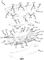
- the nacelle N therefore consists of a frame, or structural frame, or frame, 1 in which is mounted an internal envelope, or skin, 2 absorbent.
- the frame 1 is made of a rigid material such as Stamax® (polypropylene reinforced with fiberglass) or PA GF30 (polyamide reinforced with fiberglass), for example. This reinforcement 1 is intended in particular to guarantee the rigidity of the nacelle N so as to limit the deformations of the latter in the event of impact, in particular.
- the frame 1 comprises a bottom wall 11 and a side wall 12.
- the bottom wall 11 intended to support the child, is of substantially oblong shape.
- the bottom wall 11 is here full, that is to say that its upper surfaces 111 (the surface which receives the child) and lower 113 (the surface which rests on the base or the seat of the vehicle) are homogeneous and have no opening / light.
- the thickness of the bottom wall is chosen so as to provide optimum rigidity to the nacelle.
- the upper surface 111 of the bottom wall 11 that is to say the surface facing upwards and which is intended to receive the child, has three slots 112 allowing the passage of the straps of the safety harness of the child. child (not shown). These slots 112 formed in the bottom wall 11 are configured to allow the passage of the straps of the safety harness holding the child in the carrycot. More precisely, these slots 112 allow the passage of one end of the harness intended to be firmly fixed to the frame 1 of the nacelle N.
- a first opening 112a is located approximately at the level of the child's crotch when the latter is supported by the bottom wall 11.
- the other two openings 112b are located approximately at the level of the shoulders of the child when the latter. is supported by the bottom wall 11, respectively on each side of the head of the latter.
- the lumen 112a is intended to allow the attachment of the crotch strap of the child safety harness while the lumens 112b are intended to allow the attachment of the shoulder straps of the child safety harness.
- the lower surface 113 has securing means 116 which, in the illustrated embodiment, allow the attachment of the nacelle N to a base (not shown) integral with the seat of a vehicle.
- securing means 116 are for example in the form of a pair of fixing tubes or bars which extend parallel to the longitudinal axis of the bottom wall 11.
- These fixing bars 116 each extend along the rectilinear sides of the bottom wall 11 in the rear half of the latter, that is to say the part of the bottom wall 11 accommodating the lower limbs of the body. child when the latter is in the nacelle N.
- Such securing means are known and will therefore not be described in more detail here.
- Isofix® clamps In another embodiment (not illustrated), it is possible to envisage fixing the basket directly to the seat of the vehicle by means of a pair of Isofix® clamps. These Isofix® clamps would then be integral with the frame, and would extend perpendicularly to the longitudinal axis of the bottom wall 11. The implementation of such means is known and will therefore not be described in more detail here.
- the bottom wall 11 is extended, over its entire periphery, by a side wall 12 which extends substantially perpendicular to the bottom wall 11.
- the term “wall” is understood here as “surface”, but does not denote not a solid element, since the frame is, according to the invention, perforated.
- This side wall 12 is thus formed of curved uprights 120 which extend from the bottom wall 11, towards the upper edges of the nacelle N.
- this side wall is not solid, but perforated so as to limit the weight of the frame 1.
- the uprights 120 have a "U" -shaped section which optimizes their rigidity. They are arranged symmetrically with respect to an axis of symmetry 10 coincident with the longitudinal axis of the bottom wall 11.
- the side wall 12 implements eight uprights 120, that is to say four uprights arranged symmetrically on each side of the axis of symmetry 10.
- the side wall 12 has a first pair of uprights 120a located near the rear end of the bottom wall 11 (near the end of the nacelle N carrying the child's feet). These uprights 120a extend rectilinearly towards the upper edge of the nacelle N.
- a second pair of uprights 120b is located substantially in the middle of the rear half of the bottom wall 11 (half of the carrycot carrying the lower limbs of the child). These second uprights 120b extend towards the upper edge of the nacelle N according to a curve directed towards the front half of the nacelle N (half of the cradle carrying the upper limbs of the child).
- a third pair of uprights 120c is located substantially at the level of the middle of the length of the bottom wall 11. These third uprights 120c extend rectilinearly towards the upper edge of the nacelle N.
- a fourth pair of uprights 120d is located at the front end of the bottom wall 11 (in the bottom wall portion 11 located above the child's head). These fourth uprights 120d extend in a rectilinear manner towards the upper edge of the nacelle N.
- a pair of oblique braces 121 connects the ends of the fourth uprights 120b together so as to further improve the rigidity and resistance to deformation of the frame 1. As illustrated in figure 5 , these oblique braces 121 connect the ends of the fourth uprights 120d by crossing each other in their middle.
- a plurality of cross members, or bars, 122 connects the end of each upright 120 so as to form the upper rim 125 of the side wall 12 (it will be noted that, by abuse of language, in the claims, all the constituent elements of the 'reinforcement, whether they are vertical uprights, crossbars, braces or the like, are called "uprights").
- the crossbars 122 have a shape adapted to match the different heights of the uprights 120.
- the crossbars 122 have a substantially U-shaped section which makes it possible to guarantee a high rigidity of the side wall 12 for optimum weight.
- the side wall 12 of the frame 1 therefore has a plurality of openings, or recesses, 124 formed between the uprights 120, the cross members 122 and the bottom wall 11.
- the particular configuration of the frame 1 makes it possible to guarantee the nacelle N rigidity and resistance to significant deformation. More particularly, this reinforcement makes it possible to obtain, during an impact, a controlled and acceptable deformation.
- the structure of the frame 1 having a perforated side wall 12 contributes to significantly reducing its weight.
- the intersection between the sleepers 122 and the third uprights, or needles, 120c has at their upper end fixing means 123 capable of fixing a transport handle (not shown) of the nacelle N.
- fixing means which can allow a rotational movement of the handle or hold the latter rigidly are known and are therefore not described in more detail here.
- the figure 4 shows that the upper rim 125 of the wall 12 does not extend in the same plane. On the contrary, it has an asymmetrical profile with respect to a vertical plane connecting the fixing means 123.
- the rim 125 is asymmetrical in the sense that the front portion of the nacelle has a higher height relative to the bottom wall 111 of the nacelle than the rear portion.
- the cross members 122 of the flange 125 extend obliquely with different angles of inclination. More precisely, the sleepers, also called crossbowmen, 122 located in the front portion of the nacelle N have a greater tilt angle (between 20 and 50 ° relative to a horizontal plane) than the sleepers 122 located in the rear portion (between 10 and 20 ° with respect to the same horizontal plane).
- a nacelle having such an asymmetry of the upper rim 125 moves away from the known nacelles of the prior art insofar as the latter have usually a straight horizontal or slightly inclined upper rim.
- the carrycot N further comprises an internal envelope, or skin, 2 made of a material that is lighter than the frame 1.
- This internal envelope 2 has the function of ensuring the safety and restraint of the child, while ensuring comfort and a certain aesthetic to the basket.
- the inner shell 2 is made of a light material having a high degree / coefficient of shock absorption.
- the inner shell 2 is, for example, made of expanded thermoplastic polymer, such as expanded polypropylene (PPE) or expanded polystyrene (PSE) Piocelan (“registered trademark”).
- PPE expanded polypropylene
- PSE expanded polystyrene
- the inner casing 2 is, in this embodiment, a one-piece casing and comprises a bottom wall 21 extended by a peripheral wall 22 extending substantially perpendicularly to the bottom wall 21.
- the inner casing 2 is intended for be mounted / inserted into the frame 1, from inside the nacelle, and therefore has a shape complementary to that of the frame 1 and of suitable dimensions.
- the bottom wall 21 of the internal casing 2 has an upper surface 211 (the surface supporting the child) that is smooth and homogeneous so as to ensure optimal comfort and support for the transported child. It comprises three slots 212 configured to cooperate with the openings 112 of the bottom wall 11 of the frame 1, so as to allow the passage of the straps of the child's safety harness.
- the lower surface 213 of the bottom wall 21 (the surface facing the seat of the vehicle) has a profile / section adapted to the profile / section of the upper surface of the bottom wall 11 of the frame 1.
- This correspondence of the profiles surfaces of the bottom walls 11 and 21 allows a perfect superposition and a Optimal mounting / assembly of the inner casing 2 on the frame 1, so as to prevent any movement of the inner casing 2 relative to the frame 1, in particular in the event of an impact.
- the peripheral wall 22, which extends over the entire periphery of the bottom wall 21, has, in this embodiment, a different height between the front and rear halves of the nacelle N.
- the height of the peripheral wall 22 is constant and is located substantially at the same level as the intersection between the crossbars 122 and the third uprights 120c.
- the height of the peripheral wall 22 decreases from the intersection between the sleepers 122 and the third uprights 120c to the sleepers 122 located in the vicinity from the rear end of the nacelle N.
- the envelope 2 extends partially above the frame 1, and more precisely at least partly above the upper edge of this frame, by means of the elements 225 which allow the child to be better enveloped. to provide optimal comfort and improved protection in the event of an impact.
- the upper edge of the frame does not correspond to the upper part of the nacelle, but is placed significantly lower, makes it possible to optimize the rigidity of the assembly, and to reduce the dimensions of the openings.
- the inner surface 221 of the peripheral wall 22 is smooth and homogeneous so as to ensure optimal comfort and support for the child being transported.
- the outer surface 222 of the peripheral wall 22 comprises a plurality of grooves 223 of shapes corresponding to the uprights 120 and to the cross members 122.
- the outer surface 222 has protrusions, or projecting elements, 224 between the grooves 223.
- These protuberances 224 extend perpendicularly to the outer surface 222 and are of a shape corresponding to the openings 124 of the side wall 12 of the frame 1.
- a mounting clearance may be provided between the protuberances 224 and the openings 124 and / or between the grooves 223 and the uprights 120 / crossbars 122 so as to facilitate the insertion and the assembly of the inner shell 2 in the frame 1.
- This clearance can be provided in a longitudinal direction of the nacelle, that is to say that a space is left free between the edges of protuberances 224 and the edges of the openings 124, and / or between the edges of the grooves 223. and uprights 120 / sleepers 122.
- a clearance can be provided in a transverse direction of the nacelle, that is to say that the height of the protuberances 224 is slightly less than the thickness of the uprights 120 and of the cross members 122 forming the openings 124 , and / or the depth of the grooves 223 is slightly greater than the thickness of the uprights 120 and the cross members 122.
- the grooves 223 and the protuberances 224 are dimensioned so that, when the internal casing 2 is inserted into the frame 1, the outer surface of the nacelle N is smooth and homogeneous, in the sense that there is no no protrusion or protruding element and that the transition between the frame and the casing takes place in the same plane (flush).
- the smooth outer surface of the carrycot provides improved aesthetics to the carrycot and optimal comfort for the wearer when carrying the child. Indeed, the outer surface being completely smooth and having no protruding element, the risks of injury or undesirable catching for the wearer are minimized.
- the nacelle N thus comprises a frame 1 having openings so as to optimize the weight of the nacelle and its rigidity.
- An internal envelope 2 made of an energy-absorbing material, is intended to be inserted into this frame 1 so as to fill the openings made in the latter.
- the rigidity of the frame and the absorption provided by the internal envelope allow ensure the safety of the transported child by limiting the deformation of the carrycot and absorbing shocks in the event of an accident.
- Such a nacelle structure also makes it possible to provide an improved aesthetic appearance to the nacelle.
- the nacelle N of the second embodiment (illustrated in figure 8 ) consists of a frame 1 in which an absorbent inner shell 2 is mounted.
- This reinforcement intended to guarantee the rigidity of the nacelle N so as to limit the deformations of the latter in the event of an impact, comprises a bottom wall 11 and a side wall 12.
- wall is understood here. as “surface”, but does not necessarily designate a solid element, since the frame is, according to the invention, perforated.
- the bottom wall 11 is, in this embodiment, intended to receive an intermediate part 3 between the frame 1 and the internal casing 2.
- the intermediate part 3 has a shape substantially corresponding to the bottom wall 11 and has fixing means (not shown) allowing it to be secured to the upper surface 111 of the bottom wall 11.
- the intermediate part 3 is clipped to this upper surface 111. In a variant, it is envisaged to simply place the part intermediate 3 on the upper surface 111 of the bottom wall 11.
- the intermediate piece 3 is made of a flexible material, suitable for the comfort of the child, and may have a smooth upper surface 31.
- This upper surface 31 comprises three slots 311 configured to allow the passage of the straps of the safety harness which hold the child in the carrycot. More precisely, these lights 311 allow the passage of one end of the harness intended to be securely attached to frame 1 of nacelle N.
- a first opening 311a is located approximately at the level of the child's crotch when the latter is supported in the carrycot N.
- the other two openings 311b are located approximately at the level of the shoulders of the child when the latter is supported. in the nacelle N, respectively on each side of the head of the latter.
- the lumen 311a is intended to allow the attachment of the crotch strap of the child safety harness while the lumens 311b are intended to allow the attachment of the shoulder straps of the child safety harness.
- the lower surface (not visible) of the intermediate part 3 is intended to rest on the upper surface 111 of the bottom wall 11.
- This lower surface has a plurality of feet 321 extending perpendicularly to the plane of the lower surface of the part. intermediate 3, and down. These feet 321 make it possible to secure this part and, if necessary, provide a slight inclination of this intermediate part 3 relative to the upper surface 111 of the frame 1 so that the child being transported is in a comfortable position.
- the securing means referenced 116 in the first embodiment and located on the lower surface 112 (not visible) of the bottom wall 11, are not illustrated.
- These means 116 for securing the nacelle N to the base or to the seat of the vehicle are identical to those described above in the first embodiment.
- the bottom wall 11 is extended over the whole of its periphery by a side wall 12 which extends substantially perpendicularly to the bottom wall 11.
- This side wall 12 is formed of curved uprights 120 which extend from the bottom wall 11, towards the upper edges of the nacelle N.
- This side wall is not solid, but perforated so as to limit the weight of the frame 1.
- the uprights 120 have a "U" shaped section which optimizes their rigidity. They are arranged symmetrically with respect to an axis of symmetry coincident with the longitudinal axis of the bottom wall 11.
- the side wall 12 also uses eight uprights 120, that is to say four uprights arranged symmetrically on each side of the axis of symmetry.
- the uprights 120 extend essentially in the same way as in the first embodiment.
- the uprights 120a and 120d located respectively in the vicinity of the front and rear ends of the bottom wall 11 extend substantially rectilinearly towards the upper edge of the nacelle N.
- the uprights 120b which are located substantially in the middle of the rear half of the bottom wall 11, extend towards the upper edge of the nacelle N according to a curve directed towards the front half of the nacelle N.
- the uprights 120c which are located substantially at the level of the middle of the length of the bottom wall 11, extend rectilinearly towards the upper edge of the nacelle N.
- the pair of oblique braces 121 is not implemented. However, nothing would prevent its implementation in a variant of this embodiment.
- a plurality of cross members, or bars, 122 connects the upper end of each upright 120 so as to form the upper rim 125 of the side wall 12.
- the cross members 122 have a shape adapted to match the different heights of the uprights 120.
- the crossmembers 122 have a substantially “U” -shaped section which ensures high rigidity of the side wall 12 for optimum weight.
- the rim 125 differs from that of the first embodiment in that it extends substantially horizontally over the entire periphery of the nacelle N.
- the variations in height between the uprights 120 are here very small, as illustrated in the figures 8 and 9 .
- the frame 1 further comprises an inclined upright, or crossbow, 13 extending between the vertical upright, or needle 120c and the rim 125.
- the crossbow 13 extends above the rim 125 at an angle included between 10 ° and 40 ° with respect to a horizontal plane.
- the V-shaped assembly defined by the crossbowman 13 and the upper part of the needle carrying the fixing means 123 of the transport handle (not shown) of the nacelle N are removable, and / or manufactured independently of the frame. herself.
- the V-shaped assembly is an integral part of the frame 1.
- the side wall 12 of the frame 1 therefore has a plurality of openings, or recesses, 124 formed between the uprights 120, the cross members 122 and the bottom wall 11.
- Such a structure of the 'frame 1 in which the side wall 12 is perforated helps to significantly reduce its weight.
- the particular configuration of the frame 1 makes it possible to guarantee the nacelle N high rigidity and resistance to deformation. More particularly, the frame 1 of the invention makes it possible to guarantee optimum safety for the child since the latter has wide and robust uprights 120b and 120c at the level of the child's head which thus make it possible to obtain, when from an impact, a controlled deformation of the nacelle.
- the carrycot N further comprises an internal envelope 2 made of a material that is lighter than the frame 1 and which has the function of ensuring the safety and restraint of the child, while at the same time. ensuring comfort and a certain aesthetic appeal to the N.
- the inner casing 2 is a one-piece casing and comprises a bottom wall 21 extended by a peripheral wall 22 extending substantially perpendicularly to the bottom wall 21.
- the internal casing 2 is intended to be mounted / inserted into the frame 1, and therefore has a shape corresponding to that of the frame 1 and of suitable dimensions.
- the internal envelope can be made in two parts, or even more.
- the envelope 2 of the second embodiment has the same characteristics and the same advantages as in the first embodiment.
- the shape of the grooves 223 and of the protuberances 224 is adapted to the differences in shape of the structure of the frame 1 of the second embodiment described above.
- the inner casing 2 has a slot 23 which extends perpendicularly to the bottom wall 21 in the peripheral wall 22. This slot 23 makes it possible to facilitate the insertion and assembly of the inner casing 2 in the frame 1 .
- the part of the internal casing 2 which extends above the rim 125 of the frame 1 also exhibits differences. More precisely, in the first embodiment, the height of the peripheral wall 22 of the internal casing 2 extends substantially horizontally in the front half of the nacelle then decreases in the rear half of the nacelle from the intersection between the nacelle. crossmembers 122 and the third uprights 120c to crossmembers 122 located near the rear end of nacelle N.
- the height of the peripheral wall decreases from the end of the removable element 13 carrying the fixing means 123 of the handle towards each of the front and rear ends of the nacelle N.
- the peripheral wall 22 of the inner casing 2 has a maximum height at the level of the fixing means 123 (when the inner casing 1 is inserted into the frame 1).
- the height of the peripheral wall 22 is substantially identical to each of the front and rear ends of the nacelle N.
- the nacelle N may also have means 5 for dissipating the energy applied to the harnesses during an impact.
- the openings 311a and 311b formed in the intermediate part 3 each have an insert 51 which can be deformed when a force greater than a predetermined threshold (corresponding to a shock or a significant displacement, for example a situation of 'accident).
- This insert 51 is intended, as illustrated on figure 11 to deform during an impact in order to dissipate the energy applied to the harnesses and therefore to the child being transported.
- the inserts 51 are, for example, made from an expanded thermoplastic polymer, such as expanded polypropylene (PPE) or expanded polystyrene (PSE). However, any other material allowing such dissipation of energy can be used.
- PPE expanded polypropylene
- PSE expanded polystyrene
- the inserts 51 are located between the harness 52 and the lower side of the opening 311a, 311b, that is to say the side closest to the bottom of the basket carrying the lower limbs of the 'child.
- dissipation means 5 The implementation of the dissipation means 5 is illustrated here with the intermediate part 3 of the second embodiment of the nacelle N. It is understood that the dissipation means 5 can be implemented in the openings 112a and 112b of the wall of bottom 11 of the nacelle N of the first embodiment.
- the inserts can be replaced by a movable part associated with return means.
- This slot intended to receive the attachment axis of the harness has a diameter smaller than the diameter of the attachment axis of the harness.
- the harness axis deforms the slot and moves in the latter so as to absorb / dissipate the energy of the impact.
- one or more guiding elements of the Harness straps for example rods, can be mounted so as to move, and / or deform or even break to absorb the energy, and therefore reduce the forces applied to the child.
- the slits formed in the intermediate part 3 are themselves deformable, for example tearable, under the effect of a strong impact.
- an outer skin 4 (illustrated on the figures 8 and 9 ) made of lightweight plastic and mounted on the frame to provide improved aesthetics to the N pod.
- the weight of the nacelle N is less than 6 kg.
- the weight of the assembled nacelle is between 4 and 5.5 kg.
- the principle of the invention consisting in implementing, for a carrycot for transporting a child, a rigid perforated frame in which is inserted an internal envelope made of absorbent material which fills / fills the openings of the frame, in order to to guarantee optimal safety of the child while having a minimum weight, can be adapted to any device for transporting a child, such as a safety seat or a stroller, for example.
Landscapes
- Engineering & Computer Science (AREA)
- Health & Medical Sciences (AREA)
- Child & Adolescent Psychology (AREA)
- General Health & Medical Sciences (AREA)
- Aviation & Aerospace Engineering (AREA)
- Transportation (AREA)
- Mechanical Engineering (AREA)
- Body Structure For Vehicles (AREA)
- Seats For Vehicles (AREA)
- Toys (AREA)
Claims (15)
- Kinderbett (N) für den Transport eines Kindes in liegender Position, dazu bestimmt, mit dem Sitz eines Automobilfahrzeuges fest verbunden zu werden, dadurch gekennzeichnet, dass das Kinderbett (N) umfasst:- einen Rahmen (1), der eine Vielzahl von Streben (120) umfasst, die sich von einem Boden (11) aus erstrecken und mit ihrem oberen Ende durch Querstreben (122) verbunden sind, wodurch mehrere Öffnungen (124) begrenzt werden; und- eine Auskleidung (2), die im Inneren des Rahmens (1) angeordnet ist, die die Innenwände des Kinderbetts (N) bildet und Ausstülpungen aufweist, die mindestens teilweise mindestens eine der Öffnungen (124) des Rahmens (1) ausfüllen.
- Kinderbett (N) nach Anspruch 1, dadurch gekennzeichnet, dass der Rahmen an jeder Seitenfläche eine vertikale Strebe aufweist, einen sogenannten Pfosten, an dessen oberem Ende ein Griff montiert ist.
- Kinderbett nach Anspruch 2, dadurch gekennzeichnet, dass der Pfosten an der Seitenfläche im Wesentlichen in der Höhe platziert ist, wo sich der Kopf des Kindes befindet.
- Kinderbett nach einem der Ansprüche 2 und 3, dadurch gekennzeichnet, dass der Rahmen mindestens eine schräge Strebe in Bezug zur Waagerechten umfasst, einen sogenannten Sparren, dessen oberes Ende an das obere Ende des besagten Pfosten anschließt.
- Kinderbett nach Anspruch 4, dadurch gekennzeichnet, dass mindestens einer der Sparren sich bis zum unteren Teil des Rahmens fortsetzt.
- Kinderbett nach einem der Ansprüche 1 bis 5, dadurch gekennzeichnet, dass die Auskleidung (2) einteilig ist und mindestens einen Montageschlitz (23) in seiner Umfangswand aufweist.
- Kinderbett nach einem der Ansprüche 1 bis 5, dadurch gekennzeichnet, dass die Auskleidung (2) aus zwei verschiedenen Teilen gebildet ist.
- Kinderbett (N) nach einem der Ansprüche 1 bis 7, dadurch gekennzeichnet, dass die Auskleidung (2) aus geschäumtem thermoplastischen Polymer, aus geschäumtem Polypropylen oder aus geschäumtem Polystyren hergestellt ist.
- Kinderbett nach einem der Ansprüche 1 bis 8, dadurch gekennzeichnet, dass die Auskleidung (2) eine Vielzahl von Aussparungen (223) umfasst, die jeweils dazu bestimmt sind, dass jede eine der Streben (120) und/oder eine Querstrebe (123) des Rahmens (1) aufnimmt.
- Kinderbett (N) nach Anspruch 9, dadurch gekennzeichnet, dass die Auskleidung (2) zwischen den Aussparungen (223) Ausstülpungen (224) umfasst, von denen jede eine der Öffnungen (124) des Rahmens (1) ausfüllt.
- Kinderbett (N) nach Anspruch 10, dadurch gekennzeichnet, dass es einen ersten Einbausatz zwischen den Ausstülpungen (224) und den Öffnungen (124) und/oder einen zweiten Einbausatz zwischen den Aussparungen (223) und den Streben (120) und/oder den Querstreben (122) aufweist.
- Kinderbett (N) nach einem der Ansprüche 1 bis 11, dadurch gekennzeichnet, dass der Rahmen Mittel zum festen Verbinden aufweist, die es ermöglichen, das Kinderbett (N) an einer Grundplatte zu befestigen, die auf dem Sitz eines Automobilfahrzeuges montiert ist.
- Kinderbett (N) nach einem der Ansprüche 1 bis 12, dadurch gekennzeichnet, dass der Rahmen (1) Klemmen zum festen Verbinden aufweist, die es ermöglichen, das Kinderbett (N) an Einhängeschlaufen zu befestigen, die zu diesem Zweck an dem Sitz eines Automobilfahrzeuges vorgesehen sind.
- Kinderbett (N) nach einem der Ansprüche 1 bis 13, dadurch gekennzeichnet, dass sich die Auskleidung (2) über den oberen Rand (125) des Rahmens (1) erstreckt.
- Vorrichtung für den Transport eines Kindes in liegender Position, umfassend eine mit einem Automobilfahrzeug fest verbundene Grundplatte und ein Kinderbett (N) nach einem der Ansprüche 1 bis 14, das dazu bestimmt ist, mit Mitteln zum festen Verbinden an der Grundplatte befestigt zu werden.
Applications Claiming Priority (2)
| Application Number | Priority Date | Filing Date | Title |
|---|---|---|---|
| FR1656561A FR3053642B1 (fr) | 2016-07-07 | 2016-07-07 | Nacelle pour enfant presentant une armature et une enveloppe de remplissage |
| PCT/EP2017/066211 WO2018007243A1 (fr) | 2016-07-07 | 2017-06-29 | Nacelle pour enfant présentant une armature et une enveloppe de remplissage |
Publications (2)
| Publication Number | Publication Date |
|---|---|
| EP3481668A1 EP3481668A1 (de) | 2019-05-15 |
| EP3481668B1 true EP3481668B1 (de) | 2021-01-27 |
Family
ID=57348814
Family Applications (1)
| Application Number | Title | Priority Date | Filing Date |
|---|---|---|---|
| EP17732954.7A Not-in-force EP3481668B1 (de) | 2016-07-07 | 2017-06-29 | Kinderbett mit einem rahmen und einer auskleidung |
Country Status (5)
| Country | Link |
|---|---|
| EP (1) | EP3481668B1 (de) |
| CN (1) | CN109843643B (de) |
| ES (1) | ES2863658T3 (de) |
| FR (1) | FR3053642B1 (de) |
| WO (1) | WO2018007243A1 (de) |
Families Citing this family (6)
| Publication number | Priority date | Publication date | Assignee | Title |
|---|---|---|---|---|
| KR20250078631A (ko) * | 2020-05-14 | 2025-06-02 | 밤비노 프레치오조 스위처란트 아게 | 차량 또는 유모차 프레임에 분리 가능하게 부착된 베이스에 탈착 가능하게 장착되는 캐리콧 |
| CN117818736A (zh) * | 2020-05-14 | 2024-04-05 | 宝钜瑞士股份有限公司 | 睡箱、睡箱结构及婴儿载具 |
| CN113665660A (zh) * | 2020-05-14 | 2021-11-19 | 宝钜瑞士股份有限公司 | 睡箱、睡箱结构及婴儿载具 |
| CN114347881B (zh) * | 2020-10-13 | 2024-08-06 | 宝钜瑞士股份有限公司 | 睡箱 |
| CN115886496A (zh) * | 2021-09-22 | 2023-04-04 | 明门瑞士股份有限公司 | 婴儿载具及其制造方法 |
| EP4484790A3 (de) * | 2022-09-08 | 2025-01-22 | Jani International Pte. Ltd. | Träger, klemmsitzanordnung, stützrahmen und rollenbewegungsvorrichtung |
Family Cites Families (9)
| Publication number | Priority date | Publication date | Assignee | Title |
|---|---|---|---|---|
| JPS5823256B2 (ja) * | 1979-07-09 | 1983-05-13 | 株式会社 高田工場 | 乗物用幼児拘束装置 |
| FR2736609B3 (fr) * | 1995-07-12 | 1997-09-19 | Leopold Tuytschaever & Co | Landau avec nacelle amovible a placer dans un vehicule muni de ceintures de securite |
| CN2505411Y (zh) * | 2001-10-22 | 2002-08-14 | 昆山兴宝塑料制品有限公司 | 新型置物篮 |
| ES2352629B1 (es) * | 2009-07-13 | 2011-12-29 | Manuel RUIZ CARMONA | Caja para el envasado y transporte de productos |
| CN202321240U (zh) * | 2011-11-01 | 2012-07-11 | 曾明涛 | 用骨架支撑的乐器盒 |
| ES1093530Y (es) * | 2013-09-18 | 2014-02-11 | Jane S A (100 0%) | Asiento infantil de seguridad para automóviles |
| CN204169512U (zh) * | 2014-11-12 | 2015-02-25 | 厦门理工学院 | 婴儿床 |
| CN104553907B (zh) * | 2014-12-31 | 2017-09-12 | 江苏百佳斯特汽车制品有限公司 | 汽车儿童安全提篮 |
| CN204670787U (zh) * | 2015-05-19 | 2015-09-30 | 徐江林 | 一种可折叠多用婴儿提篮 |
-
2016
- 2016-07-07 FR FR1656561A patent/FR3053642B1/fr not_active Expired - Fee Related
-
2017
- 2017-06-29 ES ES17732954T patent/ES2863658T3/es active Active
- 2017-06-29 EP EP17732954.7A patent/EP3481668B1/de not_active Not-in-force
- 2017-06-29 WO PCT/EP2017/066211 patent/WO2018007243A1/fr not_active Ceased
- 2017-06-29 CN CN201780042328.1A patent/CN109843643B/zh active Active
Non-Patent Citations (1)
| Title |
|---|
| None * |
Also Published As
| Publication number | Publication date |
|---|---|
| EP3481668A1 (de) | 2019-05-15 |
| CN109843643A (zh) | 2019-06-04 |
| ES2863658T3 (es) | 2021-10-11 |
| FR3053642A1 (fr) | 2018-01-12 |
| CN109843643B (zh) | 2021-06-01 |
| FR3053642B1 (fr) | 2018-08-17 |
| WO2018007243A1 (fr) | 2018-01-11 |
Similar Documents
| Publication | Publication Date | Title |
|---|---|---|
| WO2018007243A1 (fr) | Nacelle pour enfant présentant une armature et une enveloppe de remplissage | |
| EP3390147B1 (de) | Wiege für kinder mit einem inneren rahmen mit einer asymmetrischen struktur | |
| FR2698832A1 (fr) | Structure modulaire de siège pour véhicule automobile. | |
| EP1220762B1 (de) | Stütze- und halte-struktur für die insassen eines nahverkehrsfahrzeuges | |
| WO2013175131A1 (fr) | Dispositif repose pieds pour un enfant installé dans un siège enfant dans un véhicule | |
| EP1459955B1 (de) | Transportvorrichtung für eine Last und passende Befestigungsvorrichtung | |
| EP3984859B1 (de) | Modularer schlitten | |
| FR2598366A1 (fr) | Equipement de securite adaptable entre les sieges avant d'un vehicule automobile | |
| FR2717433A1 (fr) | Siège de véhicule avec siège de sécurité pour enfants. | |
| FR2710013A1 (fr) | Dispositif de maintien latéral pour un siège de véhicule automobile et siège de véhicule pour enfant. | |
| EP0011337B1 (de) | Schutzeinrichtung zum Transport von Kindern | |
| FR2992607A1 (fr) | Dispositif de couverture arriere d'un siege de vehicule automobile, siege, rangee et vehicule comprenant un siege equipe dudit dispositif | |
| FR3136413A1 (fr) | Dispositif pour le transport d’un enfant | |
| FR2936750A1 (fr) | "siege de vehicule automobile comportant un appui-tete pouvant etre fixe au siege dans une position de rehausseur pour enfant" | |
| FR3022873A1 (fr) | Guide-sangle de ceinture de securite pour vehicule automobile | |
| FR2736609A1 (fr) | Landau avec nacelle amovible a placer dans un vehicule muni de ceintures de securite | |
| EP3718871B1 (de) | Individueller schutz gegen unwetter | |
| FR2972974A1 (fr) | Banquette allegee et resistante pour vehicule automobile | |
| FR2912102A1 (fr) | Renfort destine a etre dispose sous une coque externe mince d'un vehicule automobile | |
| WO2017140970A1 (fr) | Selle de velo | |
| FR3061458B1 (fr) | Dispositif d’ancrage pour la fixation amovible d’un siege enfant sur un siege arriere d’un vehicule automobile rabattable en portefeuille. | |
| FR3132199A1 (fr) | Chaise haute pour enfant a pietement demontable | |
| FR2513950A1 (fr) | Absorbeur d'energie cinetique | |
| FR3016835A1 (fr) | Dossier de banquette arriere de vehicule automobile | |
| FR2858292A1 (fr) | Dispositif porte-sac a monter sur une bicyclette |
Legal Events
| Date | Code | Title | Description |
|---|---|---|---|
| STAA | Information on the status of an ep patent application or granted ep patent |
Free format text: STATUS: UNKNOWN |
|
| STAA | Information on the status of an ep patent application or granted ep patent |
Free format text: STATUS: THE INTERNATIONAL PUBLICATION HAS BEEN MADE |
|
| PUAI | Public reference made under article 153(3) epc to a published international application that has entered the european phase |
Free format text: ORIGINAL CODE: 0009012 |
|
| STAA | Information on the status of an ep patent application or granted ep patent |
Free format text: STATUS: REQUEST FOR EXAMINATION WAS MADE |
|
| 17P | Request for examination filed |
Effective date: 20181217 |
|
| AK | Designated contracting states |
Kind code of ref document: A1 Designated state(s): AL AT BE BG CH CY CZ DE DK EE ES FI FR GB GR HR HU IE IS IT LI LT LU LV MC MK MT NL NO PL PT RO RS SE SI SK SM TR |
|
| AX | Request for extension of the european patent |
Extension state: BA ME |
|
| DAV | Request for validation of the european patent (deleted) | ||
| DAX | Request for extension of the european patent (deleted) | ||
| GRAP | Despatch of communication of intention to grant a patent |
Free format text: ORIGINAL CODE: EPIDOSNIGR1 |
|
| STAA | Information on the status of an ep patent application or granted ep patent |
Free format text: STATUS: GRANT OF PATENT IS INTENDED |
|
| INTG | Intention to grant announced |
Effective date: 20200116 |
|
| RIN1 | Information on inventor provided before grant (corrected) |
Inventor name: PASQUIER, NICOLAS Inventor name: PORMENTE, SYLVAINE |
|
| GRAJ | Information related to disapproval of communication of intention to grant by the applicant or resumption of examination proceedings by the epo deleted |
Free format text: ORIGINAL CODE: EPIDOSDIGR1 |
|
| STAA | Information on the status of an ep patent application or granted ep patent |
Free format text: STATUS: REQUEST FOR EXAMINATION WAS MADE |
|
| GRAR | Information related to intention to grant a patent recorded |
Free format text: ORIGINAL CODE: EPIDOSNIGR71 |
|
| GRAS | Grant fee paid |
Free format text: ORIGINAL CODE: EPIDOSNIGR3 |
|
| STAA | Information on the status of an ep patent application or granted ep patent |
Free format text: STATUS: GRANT OF PATENT IS INTENDED |
|
| INTC | Intention to grant announced (deleted) | ||
| INTG | Intention to grant announced |
Effective date: 20200529 |
|
| GRAA | (expected) grant |
Free format text: ORIGINAL CODE: 0009210 |
|
| STAA | Information on the status of an ep patent application or granted ep patent |
Free format text: STATUS: THE PATENT HAS BEEN GRANTED |
|
| AK | Designated contracting states |
Kind code of ref document: B1 Designated state(s): AL AT BE BG CH CY CZ DE DK EE ES FI FR GB GR HR HU IE IS IT LI LT LU LV MC MK MT NL NO PL PT RO RS SE SI SK SM TR |
|
| REG | Reference to a national code |
Ref country code: GB Ref legal event code: FG4D Free format text: NOT ENGLISH |
|
| REG | Reference to a national code |
Ref country code: CH Ref legal event code: EP |
|
| REG | Reference to a national code |
Ref country code: AT Ref legal event code: REF Ref document number: 1358051 Country of ref document: AT Kind code of ref document: T Effective date: 20210215 |
|
| REG | Reference to a national code |
Ref country code: IE Ref legal event code: FG4D Free format text: LANGUAGE OF EP DOCUMENT: FRENCH |
|
| REG | Reference to a national code |
Ref country code: DE Ref legal event code: R096 Ref document number: 602017032068 Country of ref document: DE |
|
| REG | Reference to a national code |
Ref country code: NL Ref legal event code: MP Effective date: 20210127 |
|
| REG | Reference to a national code |
Ref country code: LT Ref legal event code: MG9D |
|
| REG | Reference to a national code |
Ref country code: AT Ref legal event code: MK05 Ref document number: 1358051 Country of ref document: AT Kind code of ref document: T Effective date: 20210127 |
|
| PG25 | Lapsed in a contracting state [announced via postgrant information from national office to epo] |
Ref country code: BG Free format text: LAPSE BECAUSE OF FAILURE TO SUBMIT A TRANSLATION OF THE DESCRIPTION OR TO PAY THE FEE WITHIN THE PRESCRIBED TIME-LIMIT Effective date: 20210427 Ref country code: LT Free format text: LAPSE BECAUSE OF FAILURE TO SUBMIT A TRANSLATION OF THE DESCRIPTION OR TO PAY THE FEE WITHIN THE PRESCRIBED TIME-LIMIT Effective date: 20210127 Ref country code: FI Free format text: LAPSE BECAUSE OF FAILURE TO SUBMIT A TRANSLATION OF THE DESCRIPTION OR TO PAY THE FEE WITHIN THE PRESCRIBED TIME-LIMIT Effective date: 20210127 Ref country code: GR Free format text: LAPSE BECAUSE OF FAILURE TO SUBMIT A TRANSLATION OF THE DESCRIPTION OR TO PAY THE FEE WITHIN THE PRESCRIBED TIME-LIMIT Effective date: 20210428 Ref country code: HR Free format text: LAPSE BECAUSE OF FAILURE TO SUBMIT A TRANSLATION OF THE DESCRIPTION OR TO PAY THE FEE WITHIN THE PRESCRIBED TIME-LIMIT Effective date: 20210127 Ref country code: PT Free format text: LAPSE BECAUSE OF FAILURE TO SUBMIT A TRANSLATION OF THE DESCRIPTION OR TO PAY THE FEE WITHIN THE PRESCRIBED TIME-LIMIT Effective date: 20210527 Ref country code: NO Free format text: LAPSE BECAUSE OF FAILURE TO SUBMIT A TRANSLATION OF THE DESCRIPTION OR TO PAY THE FEE WITHIN THE PRESCRIBED TIME-LIMIT Effective date: 20210427 |
|
| PG25 | Lapsed in a contracting state [announced via postgrant information from national office to epo] |
Ref country code: SE Free format text: LAPSE BECAUSE OF FAILURE TO SUBMIT A TRANSLATION OF THE DESCRIPTION OR TO PAY THE FEE WITHIN THE PRESCRIBED TIME-LIMIT Effective date: 20210127 Ref country code: AT Free format text: LAPSE BECAUSE OF FAILURE TO SUBMIT A TRANSLATION OF THE DESCRIPTION OR TO PAY THE FEE WITHIN THE PRESCRIBED TIME-LIMIT Effective date: 20210127 Ref country code: PL Free format text: LAPSE BECAUSE OF FAILURE TO SUBMIT A TRANSLATION OF THE DESCRIPTION OR TO PAY THE FEE WITHIN THE PRESCRIBED TIME-LIMIT Effective date: 20210127 Ref country code: LV Free format text: LAPSE BECAUSE OF FAILURE TO SUBMIT A TRANSLATION OF THE DESCRIPTION OR TO PAY THE FEE WITHIN THE PRESCRIBED TIME-LIMIT Effective date: 20210127 Ref country code: RS Free format text: LAPSE BECAUSE OF FAILURE TO SUBMIT A TRANSLATION OF THE DESCRIPTION OR TO PAY THE FEE WITHIN THE PRESCRIBED TIME-LIMIT Effective date: 20210127 |
|
| PG25 | Lapsed in a contracting state [announced via postgrant information from national office to epo] |
Ref country code: IS Free format text: LAPSE BECAUSE OF FAILURE TO SUBMIT A TRANSLATION OF THE DESCRIPTION OR TO PAY THE FEE WITHIN THE PRESCRIBED TIME-LIMIT Effective date: 20210527 |
|
| REG | Reference to a national code |
Ref country code: ES Ref legal event code: FG2A Ref document number: 2863658 Country of ref document: ES Kind code of ref document: T3 Effective date: 20211011 |
|
| REG | Reference to a national code |
Ref country code: DE Ref legal event code: R097 Ref document number: 602017032068 Country of ref document: DE |
|
| PG25 | Lapsed in a contracting state [announced via postgrant information from national office to epo] |
Ref country code: SM Free format text: LAPSE BECAUSE OF FAILURE TO SUBMIT A TRANSLATION OF THE DESCRIPTION OR TO PAY THE FEE WITHIN THE PRESCRIBED TIME-LIMIT Effective date: 20210127 Ref country code: CZ Free format text: LAPSE BECAUSE OF FAILURE TO SUBMIT A TRANSLATION OF THE DESCRIPTION OR TO PAY THE FEE WITHIN THE PRESCRIBED TIME-LIMIT Effective date: 20210127 Ref country code: EE Free format text: LAPSE BECAUSE OF FAILURE TO SUBMIT A TRANSLATION OF THE DESCRIPTION OR TO PAY THE FEE WITHIN THE PRESCRIBED TIME-LIMIT Effective date: 20210127 |
|
| PG25 | Lapsed in a contracting state [announced via postgrant information from national office to epo] |
Ref country code: SK Free format text: LAPSE BECAUSE OF FAILURE TO SUBMIT A TRANSLATION OF THE DESCRIPTION OR TO PAY THE FEE WITHIN THE PRESCRIBED TIME-LIMIT Effective date: 20210127 Ref country code: DK Free format text: LAPSE BECAUSE OF FAILURE TO SUBMIT A TRANSLATION OF THE DESCRIPTION OR TO PAY THE FEE WITHIN THE PRESCRIBED TIME-LIMIT Effective date: 20210127 Ref country code: RO Free format text: LAPSE BECAUSE OF FAILURE TO SUBMIT A TRANSLATION OF THE DESCRIPTION OR TO PAY THE FEE WITHIN THE PRESCRIBED TIME-LIMIT Effective date: 20210127 |
|
| PLBE | No opposition filed within time limit |
Free format text: ORIGINAL CODE: 0009261 |
|
| STAA | Information on the status of an ep patent application or granted ep patent |
Free format text: STATUS: NO OPPOSITION FILED WITHIN TIME LIMIT |
|
| 26N | No opposition filed |
Effective date: 20211028 |
|
| PG25 | Lapsed in a contracting state [announced via postgrant information from national office to epo] |
Ref country code: MC Free format text: LAPSE BECAUSE OF FAILURE TO SUBMIT A TRANSLATION OF THE DESCRIPTION OR TO PAY THE FEE WITHIN THE PRESCRIBED TIME-LIMIT Effective date: 20210127 Ref country code: AL Free format text: LAPSE BECAUSE OF FAILURE TO SUBMIT A TRANSLATION OF THE DESCRIPTION OR TO PAY THE FEE WITHIN THE PRESCRIBED TIME-LIMIT Effective date: 20210127 |
|
| REG | Reference to a national code |
Ref country code: CH Ref legal event code: PL |
|
| PG25 | Lapsed in a contracting state [announced via postgrant information from national office to epo] |
Ref country code: SI Free format text: LAPSE BECAUSE OF FAILURE TO SUBMIT A TRANSLATION OF THE DESCRIPTION OR TO PAY THE FEE WITHIN THE PRESCRIBED TIME-LIMIT Effective date: 20210127 |
|
| REG | Reference to a national code |
Ref country code: BE Ref legal event code: MM Effective date: 20210630 |
|
| PG25 | Lapsed in a contracting state [announced via postgrant information from national office to epo] |
Ref country code: LU Free format text: LAPSE BECAUSE OF NON-PAYMENT OF DUE FEES Effective date: 20210629 |
|
| PG25 | Lapsed in a contracting state [announced via postgrant information from national office to epo] |
Ref country code: LI Free format text: LAPSE BECAUSE OF NON-PAYMENT OF DUE FEES Effective date: 20210630 Ref country code: IE Free format text: LAPSE BECAUSE OF NON-PAYMENT OF DUE FEES Effective date: 20210629 Ref country code: CH Free format text: LAPSE BECAUSE OF NON-PAYMENT OF DUE FEES Effective date: 20210630 |
|
| PG25 | Lapsed in a contracting state [announced via postgrant information from national office to epo] |
Ref country code: IS Free format text: LAPSE BECAUSE OF FAILURE TO SUBMIT A TRANSLATION OF THE DESCRIPTION OR TO PAY THE FEE WITHIN THE PRESCRIBED TIME-LIMIT Effective date: 20210527 |
|
| PG25 | Lapsed in a contracting state [announced via postgrant information from national office to epo] |
Ref country code: BE Free format text: LAPSE BECAUSE OF NON-PAYMENT OF DUE FEES Effective date: 20210630 |
|
| PGFP | Annual fee paid to national office [announced via postgrant information from national office to epo] |
Ref country code: IT Payment date: 20220613 Year of fee payment: 6 Ref country code: GB Payment date: 20220614 Year of fee payment: 6 |
|
| PGFP | Annual fee paid to national office [announced via postgrant information from national office to epo] |
Ref country code: FR Payment date: 20220627 Year of fee payment: 6 |
|
| PGFP | Annual fee paid to national office [announced via postgrant information from national office to epo] |
Ref country code: ES Payment date: 20220715 Year of fee payment: 6 Ref country code: DE Payment date: 20220629 Year of fee payment: 6 |
|
| PG25 | Lapsed in a contracting state [announced via postgrant information from national office to epo] |
Ref country code: NL Free format text: LAPSE BECAUSE OF NON-PAYMENT OF DUE FEES Effective date: 20210127 Ref country code: CY Free format text: LAPSE BECAUSE OF FAILURE TO SUBMIT A TRANSLATION OF THE DESCRIPTION OR TO PAY THE FEE WITHIN THE PRESCRIBED TIME-LIMIT Effective date: 20210127 |
|
| P01 | Opt-out of the competence of the unified patent court (upc) registered |
Effective date: 20230527 |
|
| PG25 | Lapsed in a contracting state [announced via postgrant information from national office to epo] |
Ref country code: HU Free format text: LAPSE BECAUSE OF FAILURE TO SUBMIT A TRANSLATION OF THE DESCRIPTION OR TO PAY THE FEE WITHIN THE PRESCRIBED TIME-LIMIT; INVALID AB INITIO Effective date: 20170629 |
|
| REG | Reference to a national code |
Ref country code: DE Ref legal event code: R119 Ref document number: 602017032068 Country of ref document: DE |
|
| GBPC | Gb: european patent ceased through non-payment of renewal fee |
Effective date: 20230629 |
|
| PG25 | Lapsed in a contracting state [announced via postgrant information from national office to epo] |
Ref country code: MK Free format text: LAPSE BECAUSE OF FAILURE TO SUBMIT A TRANSLATION OF THE DESCRIPTION OR TO PAY THE FEE WITHIN THE PRESCRIBED TIME-LIMIT Effective date: 20210127 Ref country code: DE Free format text: LAPSE BECAUSE OF NON-PAYMENT OF DUE FEES Effective date: 20240103 Ref country code: GB Free format text: LAPSE BECAUSE OF NON-PAYMENT OF DUE FEES Effective date: 20230629 |
|
| PG25 | Lapsed in a contracting state [announced via postgrant information from national office to epo] |
Ref country code: FR Free format text: LAPSE BECAUSE OF NON-PAYMENT OF DUE FEES Effective date: 20230630 |
|
| PG25 | Lapsed in a contracting state [announced via postgrant information from national office to epo] |
Ref country code: IT Free format text: LAPSE BECAUSE OF NON-PAYMENT OF DUE FEES Effective date: 20230629 |
|
| REG | Reference to a national code |
Ref country code: ES Ref legal event code: FD2A Effective date: 20240801 |
|
| PG25 | Lapsed in a contracting state [announced via postgrant information from national office to epo] |
Ref country code: MT Free format text: LAPSE BECAUSE OF FAILURE TO SUBMIT A TRANSLATION OF THE DESCRIPTION OR TO PAY THE FEE WITHIN THE PRESCRIBED TIME-LIMIT Effective date: 20210127 |
|
| PG25 | Lapsed in a contracting state [announced via postgrant information from national office to epo] |
Ref country code: ES Free format text: LAPSE BECAUSE OF NON-PAYMENT OF DUE FEES Effective date: 20230630 |
|
| PG25 | Lapsed in a contracting state [announced via postgrant information from national office to epo] |
Ref country code: ES Free format text: LAPSE BECAUSE OF NON-PAYMENT OF DUE FEES Effective date: 20230630 |
|
| PG25 | Lapsed in a contracting state [announced via postgrant information from national office to epo] |
Ref country code: TR Free format text: LAPSE BECAUSE OF FAILURE TO SUBMIT A TRANSLATION OF THE DESCRIPTION OR TO PAY THE FEE WITHIN THE PRESCRIBED TIME-LIMIT Effective date: 20210127 |