EP3473754B1 - Garniturdraht - Google Patents
Garniturdraht Download PDFInfo
- Publication number
- EP3473754B1 EP3473754B1 EP17197463.7A EP17197463A EP3473754B1 EP 3473754 B1 EP3473754 B1 EP 3473754B1 EP 17197463 A EP17197463 A EP 17197463A EP 3473754 B1 EP3473754 B1 EP 3473754B1
- Authority
- EP
- European Patent Office
- Prior art keywords
- tooth
- card wire
- clothing
- longitudinal direction
- angle
- Prior art date
- Legal status (The legal status is an assumption and is not a legal conclusion. Google has not performed a legal analysis and makes no representation as to the accuracy of the status listed.)
- Active
Links
Images
Classifications
-
- D—TEXTILES; PAPER
- D01—NATURAL OR MAN-MADE THREADS OR FIBRES; SPINNING
- D01G—PRELIMINARY TREATMENT OF FIBRES, e.g. FOR SPINNING
- D01G15/00—Carding machines or accessories; Card clothing; Burr-crushing or removing arrangements associated with carding or other preliminary-treatment machines
- D01G15/02—Carding machines
- D01G15/12—Details
- D01G15/26—Arrangements or disposition of carding elements
-
- D—TEXTILES; PAPER
- D01—NATURAL OR MAN-MADE THREADS OR FIBRES; SPINNING
- D01G—PRELIMINARY TREATMENT OF FIBRES, e.g. FOR SPINNING
- D01G15/00—Carding machines or accessories; Card clothing; Burr-crushing or removing arrangements associated with carding or other preliminary-treatment machines
- D01G15/84—Card clothing; Manufacture thereof not otherwise provided for
- D01G15/88—Card clothing; Manufacture thereof not otherwise provided for formed from metal sheets or strips
-
- D—TEXTILES; PAPER
- D01—NATURAL OR MAN-MADE THREADS OR FIBRES; SPINNING
- D01G—PRELIMINARY TREATMENT OF FIBRES, e.g. FOR SPINNING
- D01G15/00—Carding machines or accessories; Card clothing; Burr-crushing or removing arrangements associated with carding or other preliminary-treatment machines
- D01G15/02—Carding machines
- D01G15/12—Details
- D01G15/46—Doffing or like arrangements for removing fibres from carding elements; Web-dividing apparatus; Condensers
- D01G15/465—Doffing arrangements for removing fibres using, or cooperating with, pneumatic means
Definitions
- the invention relates to a clothing wire for a roller of a carding machine.
- a fiber web can be produced from a fiber material by the carding process.
- the fiber pile consists of a loose composite of ordered individual fibers.
- a fleece for example, can be produced from such a fiber web.
- the fiber web is created during carding by removing the fibers from a large clothing roller, also known as a tambour, with the help of a removal device and gathering them together.
- the carding machine can have different clothing rollers. Each clothing roller is covered with teeth, prongs or points that project approximately radially outward. The number and / or the size / or the density of the teeth, serrations or points, their shape and shape can vary.
- the clothing rollers are usually provided with all-steel clothing. These consist of a profiled clothing wire that is wound onto the relevant clothing roller under tension.
- the trim wire has a foot section and a blade section.
- the foot section can, for example, be rectangular or square in cross section.
- the blade section protrudes from the foot section, in the position of use approximately transversely to the jacket surface of the clothing roller.
- a sawtooth profile is provided on the blade section to form the teeth or prongs.
- the clothing wire is wound around the outer surface of the clothing roller under longitudinal tension and the two ends are attached to the clothing roller.
- Set wires are known in many different designs.
- special Proposed groups of clothing wires each with specific geometric features.
- the EP2489766A2 discloses an all-steel clothing which is formed from two clothing wires with different tooth geometries which are drawn next to one another on a clothing roller.
- the first clothing wire has a negative working angle and a tip surface, while the second clothing wire has a positive working angle.
- This combination is intended to create an all-steel clothing which, on the one hand, has the necessary aggressiveness and, on the other hand, prevents the fibers from penetrating into the clothing and ultimately preventing the clothing from clogging. Every single one of the two clothing wires cannot meet the requirements of the all-steel clothing.
- the WO00 / 26450A1 , the WO2011 / 138322A1 and the WO2013 / 037711A1 show clothing wires that are particularly suitable for so-called worker rolls, doffer rolls or transfer rolls.
- the teeth of these clothing wires are typically punched in relatively deep compared to the total height of the clothing wire and their tooth face is inclined relatively sharply forwards in the direction of the foot section.
- the tooth face is the side of the tooth that comes into direct contact with the fibers during carding.
- the specified publications show areas of the tooth face which are inclined even further towards the foot of the clothing in order to increase the carding effect of the clothing.
- a region of the tooth face that is more inclined towards the foot of the set can be referred to as an undercut.
- the WO2013 / 037711A1 therefore proposes to further the WO00 / 26450A1 a special geometry in the course of the tooth face, especially in the undercut.
- the object is achieved by a clothing wire according to claim 1.
- the clothing wire according to the invention is particularly suitable for a consumer clothing, a workers clothing or a transmission clothing.
- the clothing wire In its longitudinal direction, the clothing wire has successive teeth which are arranged spaced apart in the longitudinal direction.
- the spacing of the division can advantageously be measured from tooth tip to tooth tip.
- the teeth are delimited in the longitudinal direction on a first side by a tooth face and on a second side by a tooth back.
- the tooth face and the tooth back of successive teeth viewed downwards in the vertical direction of the clothing wire, merge into one another in a tooth base. Viewed upwards in the vertical direction of the clothing wire, the tooth face and the tooth back form the tooth tip at their intersection.
- the tooth depth is determined by the greatest distance in the vertical direction of the clothing wire from the tooth tip to the tooth base.
- the clothing wire according to the invention is characterized in that a distance, measured perpendicular to a tangent to a point of inflection between the back of the tooth and the base of the tooth, from this point of inflection to the opposite tooth face is greater than a quarter of the pitch. It is also advantageous if the distance is greater than the quotient of the division and 3.5 or greater than the quotient of the division and 3.
- the turning point in the transition from the tooth back to the tooth bottom can be clearly determined as follows. Apart from local shaped elements such as elevations or depressions, the tooth back has a tangent essentially at every point, which includes an acute angle to the longitudinal direction. In the tooth base there is at least one point at which the tangent to the clothing wire runs in the longitudinal direction. Starting from this point with a tangent in the longitudinal direction to the back of the tooth, the turning point is at the first point at which the angle of the tangent at this point assumes a smaller or equal angle to the longitudinal direction compared to the closest previous point.
- the clothing wire according to the invention preferably has a pitch smaller than 3.2 mm. A division of less than 2.6 mm is particularly advantageous.
- the set wire can have an angle to the longitudinal direction of between 45 ° and 65 ° in the tooth face.
- the set wire can have an angle to the longitudinal direction of between 50 ° and 60 ° in the tooth face.
- This angular range can particularly advantageously be present on the tooth face below any steeper tip section that may be present and below any undercut that may be present.
- the tooth face can run straight and have a single angular value from this range. However, it is also possible that the tooth face is curved and assumes different angles from this angular range in the course of the tooth face.
- the tooth base of the clothing wire can be designed in the shape of a circular arc.
- a rounded tooth base is particularly advantageous because then there are no edges or corners where fibers can easily get stuck.
- the rounded tooth base advantageously merges tangentially and without kinking into the adjacent tooth back and the adjacent tooth face.
- the radius in the tooth base of the clothing wire can be greater than one eighth of the pitch.
- a radius greater than 0.4 mm can be particularly advantageous.
- a radius larger than a seventh or a sixth of the division is also advantageous.
- the clothing wire can have a tooth back with two or more straight sections.
- a straight section that adjoins the tooth base can have a greater angle to the longitudinal direction of the clothing wire than another straight section of the tooth back.
- the straight section adjoining the tooth base preferably merges tangentially into the tooth base.
- the straight section of the The back of the tooth of the clothing wire preferably extends up to a maximum of 50% of the tooth depth in the direction of the tip. On the one hand, this ensures that the teeth can have the required spacing in the tooth base.
- the teeth can still be designed with the required small pitch and yet with a small angle to the longitudinal direction in the tooth face or with an undercut.
- the clothing wire can have an undercut in the tooth face.
- the undercut is more inclined to the longitudinal direction than the part of the tooth face adjoining at the bottom. In other words, the undercut has a smaller angle to the longitudinal direction than the adjoining part of the tooth face.
- the angle of the undercut is preferably between 0 ° and 40 ° to the longitudinal direction.
- the angle of the undercut can be between 5 ° and 35 ° to the longitudinal direction.
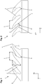
- FIG. 1 shows a clothing wire (1) according to the prior art.
- a section of clothing wire is shown which comprises 4 teeth (2).
- the clothing wire (1) is shown in a view perpendicular to the longitudinal direction (L) and perpendicular to the vertical direction (H).
- the division (3) and the tooth depth (7) are shown with arrows.
- the pitch (3) is measured in the longitudinal direction (L), the tooth depth (7) in the height direction (H).
- the auxiliary lines for the arrow to show the division (3) are applied to two tooth tips (8) of consecutive teeth (2).
- the arrow to represent the tooth depth (7) is shown between the deepest point of a tooth base (6) and on an auxiliary line, which in turn is applied to a tooth tip (8).
- the illustrated clothing wire (1) has an undercut (11).
- the tooth back (5) and the tooth face (4) run straight below the undercut (11). Above the undercut (11) in the direction of the tip, the tooth back (5) and the tooth face (4) have a deviating area.
- the trim wire according to the invention in Figure 2 corresponds to a large extent to the clothing wire Figure 1 .
- the clothing wire (1) has a spacing (9) which is greater than a quarter of the pitch (3).
- the distance (9) is measured from a turning point (10) at the transition from the tooth base (6) to the tooth back (5) to the opposite tooth face (4).
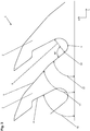
- Figure 3 a section from Figure 2 shown enlarged.
- Figure 3 shows two teeth (2) of a clothing wire (1) according to the invention.
- the foot section is no longer shown in full, but at the bottom of the Figure 3 cut off.
- the distance (9) starting from the point of inflection (10) is measured at an angle of 90 ° to the tangent at the point of inflection (10).
- the tooth base (6) runs in the shape of a circular arc and merges tangentially into the tooth back (5).
- the tooth back (5) runs straight.
- the angle of the tangent at the turning point (10) at which the circular arc of the tooth base (6) merges tangentially into the adjacent straight line of the tooth back (5), does not change in the entire first straight section of the tooth back (5).
- the turning point (10) is clearly defined at the point shown in accordance with its definition.
- the straight area adjoining the tooth base (6) has a larger angle (12) to the longitudinal direction (L) than the angle (13) of a straight area arranged further up.
- the angle (14) of the tooth face (4) is shown for the sake of completeness.
- List of reference symbols 1 Trim wire 2 tooth 3 division 4th Tooth face 5 Tooth back 6th Tooth base 7th Tooth depth 8th Tooth tip 9 distance 10
- Longitudinal direction of the trim wire H Direction of height of the trim wire
Landscapes
- Engineering & Computer Science (AREA)
- Textile Engineering (AREA)
- Preliminary Treatment Of Fibers (AREA)
Description
- Die Erfindung betrifft einen Garniturdraht für eine Walze einer Kardiermaschine.
- Kardiermaschinen, Karden oder Krempeln werden dazu verwendet die Fasern eines Fasermaterials, beispielsweise einer Wolle, Baumwolle oder auch von Kunstfasern oder eines Fasergemischs zu öffnen (zu vereinzeln) bzw. auszurichten, zu homogenisieren (in der Vliesherstellung) und/oder zu parallelisieren (in der Garnherstellung). Durch den Kardiervorgang kann aus einem Fasermaterial ein Faserflor erzeugt werden. Der Faserflor besteht aus einem losen Verbund geordneter Einzelfasern. Aus einem solchen Faserflor kann beispielweise ein Vlies hergestellt werden. Der Faserflor entsteht beim Kardieren, indem die Fasern von einer auch als Tambour bezeichneten großen Garniturwalze mit Hilfe eines Abnahmemittels abgenommen und zusammengefasst werden.
- Die Kardiermaschine kann verschiedene Garniturwalzen aufweisen. Jede Garniturwalze ist mit in etwa radial nach außen stehenden Zähnen, Zacken oder Spitzen besetzt. Die Anzahl und/oder die Größe/oder die Dichte der Zähne, Zacken oder Spitzen, deren Form und Gestalt kann variieren.
- Die Garniturwalzen sind üblicherweise mit Ganzstahlgarnituren versehen. Diese bestehen aus einem profilierten Garniturdraht, der unter Spannung auf die betreffende Garniturwalze aufgewickelt ist. Der Garniturdraht weist einen Fußabschnitt und einen Blattabschnitt auf. Der Fußabschnitt kann im Querschnitt beispielsweise rechteckförmig oder quadratisch sein. Vom Fußabschnitt ragt der Blattabschnitt weg, in Gebrauchslage in etwa quer zur Mantelfläche der Garniturwalze. Am Blattabschnitt ist ein Sägezahnprofil zur Bildung der Zähne oder Zacken vorhanden. Der Garniturdraht wird um die Mantelfläche der Garniturwalze herum unter Längsspannung aufgewickelt und die beiden Enden werden an der Garniturwalze befestigt.
- Garniturdrähte sind in vielen verschiedenen Ausführungen bekannt. Für verschiedene Funktionen der jeweiligen Garniturwalze in der Kardiermaschine werden auch spezielle Gruppen von Garniturdrähten mit jeweils spezifischen geometrischen Merkmalen vorgeschlagen.
- Die
EP2489766A2 offenbart eine Ganzstahlgarnitur, die aus zwei Garniturdrähten mit unterschiedlicher Zahngeometrie, die nebeneinander auf einer Garniturwalze aufgezogen sind, gebildet ist. Der erste Garniturdraht weist einen negativen Arbeitswinkel und eine Spitzenfläche auf, während der zweite Garniturdraht einen positiven Arbeitswinkel aufweist. Durch diese Kombination soll eine Ganzstahlgarnitur geschaffen werden, die einerseits eine nötige Aggressivität aufweist und andererseits ein Eindringen der Fasern in die Garnitur und letztlich ein Zusetzen der Garnitur vermeidet. Jeder einzelne der zwei Garniturdrähte kann die Anforderungen an die Ganzstahlgarnitur nicht erfüllen.
DieWO00/26450A1 WO2011/138322A1 und dieWO2013/037711A1 zeigen Garniturdrähte, die besonders für sogenannte Arbeiterwalzen, Abnehmerwalzen oder Übertragungswalzen geeignet sind. Die Zähne dieser Garniturdrähte sind typischerweise im Vergleich zu Gesamthöhe des Garniturdrahts relativ tief eingestanzt und sind mit ihrer Zahnbrust relativ stark nach vorne in Richtung auf den Fußabschnitt geneigt. Die Zahnbrust ist die Seite des Zahnes, die mit den Fasern beim Kardieren in direkten Kontakt tritt. Die angegebenen Druckschriften zeigen Bereiche der Zahnbrust, die nochmals weiter zum Fuß der Garnitur geneigt sind, um die Kardierwirkung der Garnitur zu erhöhen. Ein stärker zum Fuß der Garnitur geneigter Bereich der Zahnbrust kann als Hinterschnitt bezeichnet werden. Durch einen solchen Hinterschnitt kann die Stabilität der Zähne negativ beeinflusst werden, insbesondere wenn die aufeinander abfolgenden Zähne näher zusammenrücken. DieWO2013/037711A1 schlägt deshalb zur Weiterbildung derWO00/26450A1 - Bei den Garniturdrähten in den oben angegebenen Druckschriften, aber auch bei Garniturdrähten für Arbeiterwalzen, Abnehmerwalzen oder Übertragungswalzen ohne einen Hinterschnitt, ergibt sich bei im Vergleich zur Zahntiefe kleiner Teilung der Zähne das Problem, dass sich im Zahnausschnitt in Richtung auf den Zahngrund Fasern verklemmen können und sich die Garnitur mit der Zeit zusetzt. Auch wenn im unteren Bereich des Zahnausschnitts (in der Nähe des Zahngrunds) normalerweise nicht viele Fasern gehalten werden, kann es schnell zu einer unerwünschten Ansammlung von Fasern kommen, wenn erste Fasern eingeklemmt wurden.
- Es ist die Aufgabe dieser Erfindung einen Garniturdraht anzugeben, bei dem das Verklemmen von Fasern verringert und das Zusetzen der Garnitur reduziert wird.
- Die Aufgabe wird durch einen Garniturdraht gemäß Anspruch 1 gelöst.
- Der erfindungsgemäße Garniturdraht ist insbesondere für eine Abnehmergarnitur, eine Arbeitergarnitur oder eine Übertragungsgarnitur geeignet. In seiner Längsrichtung weist der Garniturdraht aufeinander folgende Zähne auf, die in der Längsrichtung in einer Teilung beabstandet angeordnet sind. Das Abstandsmaß der Teilung kann vorteilhaft von Zahnspitze zu Zahnspitze gemessen werden. Die Zähne sind in Längsrichtung von einer ersten Seite von einer Zahnbrust und von einer zweiten Seite von einem Zahnrücken begrenzt. Die Zahnbrust und der Zahnrücken von aufeinander folgenden Zähnen gehen, in der Höhenrichtung des Garniturdrahts nach unten betrachtet, in einem Zahngrund in einander über. In der Höhenrichtung des Garniturdrahts nach oben betrachtet bilden die Zahnbrust und der Zahnrücken an ihrem Schnittpunkt die Zahnspitze. Die Zahntiefe ist durch den größten Abstand in der Höhenrichtung des Garniturdrahts von der Zahnspitze zum Zahngrund bestimmt. Wenn ein rechnerisches Verhältnis von der Teilung zu Zahntiefe kleiner als 1,1 ist, ergeben sich im Zahnausschnitt Verhältnisse, die ein Verklemmen von Fasern im unteren Bereich des Zahnausschnitts begünstigen. Der erfindungsgemäße Garniturdraht ist dadurch gekennzeichnet, dass ein Abstand, gemessen senkrecht zu einer Tangente an einen Wendepunkt zwischen Zahnrücken und Zahngrund, von diesem Wendpunkt zur gegenüberliegenden Zahnbrust größer ist als ein Viertel der Teilung. Vorteilhaft ist es auch, wenn der Abstand größer als der Quotient aus der Teilung und 3,5 oder größer als der Quotient aus der Teilung und 3 ist. Durch den vergrößerten Abstand im unteren Bereich des Zahnausschnitts zwischen aufeinanderfolgenden Zähnen verklemmen in diesem unteren Bereich des Zahnausschnittes seltener Fasern und die Garnitur setzt sich weniger häufig zu. Durch den größeren Abstand entsteht zusätzlich der synergetische Effekt, dass die Oberfläche an der Zahnbrust bei vielen der betreffenden Garniturdrähte glatter ist. Dadurch wird das anfängliche Verklemmen von Fasern weiter verringert, weil die Fasern leichter an der Oberfläche abgleiten können. Bei den meisten der betreffenden Garniturdrähten findet bekanntermaßen zu einem späten Zeitpunkt während der Herstellung eine Bearbeitung der Oberfläche statt, die auch zu einer Glättung der Oberfläche führt. Diese Bearbeitung führt bei größerem Abstand zwischen den Zähnen zu einer besseren Glättung.
- Der Wendepunkt im Übergang vom Zahnrücken zum Zahngrund kann wie folgt eindeutig bestimmt werden. Der Zahnrücken weist abgesehen von lokalen Formelementen wie Erhöhungen oder Vertiefungen im Wesentlichen an jeder Stelle eine Tangente auf, die einen spitzen Winkel zur Längsrichtung einschließt. Im Zahngrund gibt es mindestens eine Stelle, an der die Tangente an den Garniturdraht in Längsrichtung verläuft. Ausgehend von dieser Stelle mit einer Tangente in Längsrichtung zum Zahnrücken liegt der Wendepunkt an der ersten Stelle, an der der Winkel der Tangente an dieser Stelle im Vergleich zum nächstliegenden vorherigen Punkt einen kleineren oder gleich großen Winkel zur Längsrichtung annimmt.
- Der erfindungsgemäße Garniturdraht weist vorzugsweise eine Teilung kleiner als 3,2mm auf. Besonders vorteilhaft liegt eine Teilung kleiner 2,6mm vor.
- Der Garniturdraht kann in der Zahnbrust einen Winkel zur Längsrichtung zwischen 45° und 65° aufweisen. Der Garniturdraht kann in der Zahnbrust einen Winkel zur Längsrichtung zwischen 50° und 60° aufweisen. Dieser Winkelbereich kann an der Zahnbrust besonders vorteilhaft unterhalb eines eventuell vorliegenden steileren Spitzenabschnitts und unterhalb eines eventuell vorliegenden Hinterschnitts vorliegen. Die Zahnbrust kann dabei gerade verlaufen und einen einzigen Winkelwert aus diesem Bereich aufweisen. Es ist aber auch möglich, dass die Zahnbrust gebogen verläuft und im Verlauf der Zahnbrust verschiedene Winkel aus diesem Winkelbereich annimmt.
- Der Garniturdraht kann im Zahngrund kreisbogenförmig ausgestaltet sein. Ein gerundet verlaufender Zahngrund ist besonders vorteilhaft, weil dann keine Kanten oder Ecken auftreten, an denen Fasern leichter verklemmen. Vorteilhafterweise geht der gerundete Zahngrund tangential und ohne Knick in den angrenzenden Zahnrücken und die angrenzende Zahnbrust über.
- Der Radius im Zahngrund des Garniturdrahts kann größer als ein Achtel der Teilung sein. Besonders vorteilhaft kann ein Radius größer als 0,4mm sein. Vorteilhaft ist auch ein Radius größer als ein Siebtel oder ein Sechstel der Teilung.
- Der Garniturdraht kann einen Zahnrücken mit zwei oder mehr geraden Abschnitten aufweisen. Ein gerader Abschnitt, der an den Zahngrund angrenzt, kann einen größeren Winkel zur Längsrichtung des Garniturdrahts aufweisen, als ein anderer gerader Abschnitt des Zahnrückens. Der an den Zahngrund angrenzende gerade Abschnitt geht vorzugsweise tangential in den Zahngrund über. Der an den Zahngrund angrenzende, gerade Abschnitt des Zahnrückens des Garniturdrahts reicht vorzugsweise bis maximal 50% der Zahntiefe in Richtung auf die Spitze nach oben. Dadurch wird zum Einen sichergestellt, dass die Zähne den erforderlichen Abstand im Zahngrund aufweisen können. Zum Anderen können die Zähne dadurch aber dennoch mit der erforderlichen kleinen Teilung und doch mit einem kleinen Winkel zur Längsrichtung in der Zahnbrust oder mit einem Hinterschnitt ausgeführt werden.
- Der Garniturdraht kann einen Hinterschnitt in der Zahnbrust aufweisen. Der Hinterschnitt ist stärker zur Längsrichtung geneigt als der unten anschließende Teil der Zahnbrust. In anderen Worten weist der Hinterschnitt einen kleineren Winkel zur Längsrichtung auf als der anschließende Teil der Zahnbrust. Der Winkel des Hinterschnitts beträgt vorzugsweise zwischen 0° und 40° zur Längsrichtung. Der Winkel des Hinterschnitts kann zwischen 5° und 35° zur Längsrichtung betragen.
- Der Fußabschnitt kann für den erfindungsgemäßen Garniturdraht nach der jeweiligen genauen Anwendung frei ausgewählt werden. Es können zum Beispiel prismen- oder v-förmige verkettete oder einfache rechteckförmige Fußformen am Garniturdraht vorliegen.
- Fig. 1
-
Figur 1 zeigt einen Garniturdraht nach dem Stand der Technik - Fig. 2
-
Figur 2 zeigt ein Ausführungsbeispiel eines erfindungsgemäßen Garniturdrahts - Fig. 3
-
Figur 3 zeigt einen vergrößerten Ausschnitt ausFigur 2 -
Figur 1 zeigt einen Garniturdraht (1) nach dem Stand der Technik. Es ist ein Abschnitt eines Garniturdrahtes gezeigt, der 4 Zähne (2) umfasst. Der Garniturdraht (1) ist in einer Ansicht senkrecht zur Längsrichtung (L) und senkrecht zur Höhenrichtung (H) dargestellt. Die Teilung (3) und die Zahntiefe (7) sind mit Pfeilen dargestellt. Die Teilung (3) wird in Längsrichtung (L), die Zahntiefe (7) in Höhenrichtung (H) gemessen. Die Hilfslinien für den Pfeil zur Darstellung der Teilung (3) sind an zwei Zahnspitzen (8) von aufeinanderfolgenden Zähnen (2) angelegt. Der Pfeil zur Darstellung der Zahntiefe (7) ist zwischen der tiefsten Stelle eines Zahngrunds (6) und an einer Hilfslinie, die wiederum an einer Zahnspitze (8) angelegt ist, dargestellt. Der dargestellte Garniturdraht (1) weist einen Hinterschnitt (11) auf. Der Zahnrücken (5) und die Zahnbrust (4) verlaufen unterhalb des Hinterschnitts (11) gerade. Oberhalb des Hinterschnitts (11) in Richtung zur Spitze weisen der Zahnrücken (5) und die Zahnbrust (4) einen abweichend verlaufenden Bereich auf. - Der erfindungsgemäße Garniturdraht in
Figur 2 entspricht zu großen Teilen dem Garniturdraht ausFigur 1 . Im Zahngrund (6) weist der Garniturdraht (1) einen Abstand (9) auf, der größer ist als ein Viertel der Teilung (3). Der Abstand (9) wird gemessen von einem Wendepunkt (10) am Übergang vom Zahngrund (6) zum Zahnrücken (5) zur gegenüberliegenden Zahnbrust(4). Zur besseren Übersicht ist inFigur 3 ein Ausschnitt ausFigur 2 vergrößert dargestellt. -
Figur 3 zeigt zwei Zähne (2) eines erfindungsgemäßen Garniturdrahts (1). Der Fußabschnitt ist nicht mehr vollständig abgebildet, sondern am unteren Rand derFigur 3 abgeschnitten. Insbesondere ist zu erkennen, dass der Abstand (9) ausgehend vom Wendepunkt (10) unter einem Winkel von 90° zur Tangente am Wendepunkt (10) gemessen wird. Der Zahngrund (6) verläuft kreisbogenförmig und geht tangential in den Zahnrücken (5) über. Ausgehend vom Wendepunkt (10) nach oben verläuft der Zahnrücken (5) gerade. Der Winkel der Tangente am Wendepunkt (10), an dem der Kreisbogen des Zahngrunds (6) tangential in die angrenzende Gerade des Zahnrückens (5) übergeht, ändert sich im gesamten ersten geraden Abschnitt des Zahnrückens (5) nicht. Dadurch ist der Wendepunkt (10) gemäß seiner Definition eindeutig an der gezeigten Stelle festgelegt. Der an den Zahngrund (6) angrenzende gerade Bereich hat einen größeren Winkel (12) zur Längsrichtung (L) als der Winkel (13) eines weiter oben angeordneten geraden Bereichs. Der Winkel (14) der Zahnbrust (4) ist der Vollständigkeit halber dargestellt.Bezugszeichenliste 1 Garniturdraht 2 Zahn 3 Teilung 4 Zahnbrust 5 Zahnrücken 6 Zahngrund 7 Zahntiefe 8 Zahn spitze 9 Abstand 10 Wendepunkt 11 Hinterschnitt 12 Winkel des an den Zahngrund angrenzenden geraden Abschnitts des Zahnrückens 13 Winkel eines weiteren geraden Abschnitts 14 Winkel der Zahnbrust L Längsrichtung des Garniturdrahts H Höhenrichtung des Garniturdrahts
Claims (9)
- Garniturdraht (1) insbesondere für eine Abnehmergarnitur, eine Arbeitergarnitur oder eine Übertragungsgarnitur, der in seiner Längsrichtung (L) aufeinander folgende Zähne (2), die in der Längsrichtung (L) in einer Teilung (3) beabstandet angeordnet sind, aufweist,
wobei die Zähne (2) in Längsrichtung (L) von einer ersten Seite von einer Zahnbrust (4) und von einer zweiten Seite von einem Zahnrücken (5) begrenzt sind,
wobei die Zahnbrust (4) und der Zahnrücken (5) von aufeinander folgenden Zähnen (2) in der Höhenrichtung (H) des Garniturdrahts (1) nach unten in einem Zahngrund (6) in einander übergehen und in der Höhenrichtung (H) des Garniturdrahts (1) nach oben eine Zahnspitze (8) bilden,
wobei die Zahntiefe (7) durch den größten Abstand in Höhenrichtung (H) des Garniturdrahts (1) von der Zahnspitze (8) zum Zahngrund (6) bestimmt ist,
wobei ein Verhältnis von Teilung (3) zu Zahntiefe (7) kleiner als 1,1 ist, dadurch gekennzeichnet, dass
ein Abstand (9), gemessen senkrecht zu einer Tangente an einen Wendepunkt (10) zwischen Zahnrücken (5) und Zahngrund (6), von diesem Wendpunkt (10) zur gegenüberliegenden Zahnbrust (4) größer ist als ein Viertel der Teilung (3), wobei der Wendepunkt (10), ausgehend von einer Stelle im Zahngrund (6), an der die Tangente an den Garniturdraht (1) in Längsrichtung (L) verläuft, zum Zahnrücken (5), an der ersten Stelle liegt, an der der Winkel der Tangente dieser Stelle im Vergleich zum nächstliegenden vorherigen Punkt einen kleineren oder gleich großen Winkel zur Längsrichtung (L) annimmt. - Garniturdraht (1) nach Anspruch 1
dadurch gekennzeichnet, dass
die Teilung (3) kleiner als 3,2mm ist. - Garniturdraht (1) nach einem der vorhergehenden Ansprüche
dadurch gekennzeichnet, dass
der Winkel der Zahnbrust (4) zur Längsrichtung (L) zwischen 45° und 65° beträgt. - Garniturdraht (1) nach einem der vorhergehenden Ansprüche
dadurch gekennzeichnet, dass
der Zahngrund (6) kreisbogenförmig ausgeformt ist. - Garniturdraht (1) nach dem vorhergehenden Anspruch
dadurch gekennzeichnet, dass
der Zahngrund (6) einen Radius größer als ein Achtel der Teilung (3) und/oder größer als 0,4mm, aufweist. - Garniturdraht (1) nach einem der vorhergehenden Ansprüche
dadurch gekennzeichnet, dass
der Zahnrücken (5) mindestens zwei gerade Abschnitte umfasst, wobei ein gerader Abschnitt, der an den Zahngrund (6) angrenzt, einen größeren Winkel zur Längsrichtung (L) aufweist als ein anderer gerader Abschnitt. - Garniturdraht (1) nach dem vorhergehenden Anspruch
dadurch gekennzeichnet, dass
der an den Zahngrund (6) angrenzende gerade Abschnitt bis maximal 50% der Zahntiefe (7) reicht. - Garniturdraht (1) nach einem der vorhergehenden Ansprüche
dadurch gekennzeichnet, dass
ein Hinterschnitt (11) in der Zahnbrust (4) vorliegt. - Garniturdraht (1) nach Anspruch 8
dadurch gekennzeichnet, dass
der Hinterschnitt (11) in der Zahnbrust (4) einen Winkel von 0° bis 45° zur Längsrichtung (L) aufweist.
Priority Applications (6)
| Application Number | Priority Date | Filing Date | Title |
|---|---|---|---|
| EP17197463.7A EP3473754B1 (de) | 2017-10-20 | 2017-10-20 | Garniturdraht |
| BR102018014143-0A BR102018014143B1 (pt) | 2017-10-20 | 2018-07-11 | Arame de carda |
| JP2018179205A JP2019077978A (ja) | 2017-10-20 | 2018-09-25 | カードワイヤ |
| KR1020180123674A KR102652089B1 (ko) | 2017-10-20 | 2018-10-17 | 카드 와이어 |
| US16/165,338 US10988863B2 (en) | 2017-10-20 | 2018-10-19 | Card wire |
| CN201811222115.XA CN109695075B (zh) | 2017-10-20 | 2018-10-19 | 梳针 |
Applications Claiming Priority (1)
| Application Number | Priority Date | Filing Date | Title |
|---|---|---|---|
| EP17197463.7A EP3473754B1 (de) | 2017-10-20 | 2017-10-20 | Garniturdraht |
Publications (2)
| Publication Number | Publication Date |
|---|---|
| EP3473754A1 EP3473754A1 (de) | 2019-04-24 |
| EP3473754B1 true EP3473754B1 (de) | 2021-05-19 |
Family
ID=60153161
Family Applications (1)
| Application Number | Title | Priority Date | Filing Date |
|---|---|---|---|
| EP17197463.7A Active EP3473754B1 (de) | 2017-10-20 | 2017-10-20 | Garniturdraht |
Country Status (5)
| Country | Link |
|---|---|
| US (1) | US10988863B2 (de) |
| EP (1) | EP3473754B1 (de) |
| JP (1) | JP2019077978A (de) |
| KR (1) | KR102652089B1 (de) |
| CN (1) | CN109695075B (de) |
Families Citing this family (2)
| Publication number | Priority date | Publication date | Assignee | Title |
|---|---|---|---|---|
| CN110938899B (zh) * | 2019-12-16 | 2024-07-05 | 光山白鲨针布有限公司 | 高速高产道夫金属针布 |
| EP4269672A1 (de) * | 2022-04-26 | 2023-11-01 | Groz-Beckert KG | Kardengarniturdraht, kardiermaschine und verfahren zur herstellung eines vliesstoffes |
Family Cites Families (12)
| Publication number | Priority date | Publication date | Assignee | Title |
|---|---|---|---|---|
| ES288973Y (es) * | 1984-10-11 | 1987-02-01 | Sole Leris Roger | Guarnicion rigida para chapones para cardas perfeccionada. |
| DE19509743A1 (de) * | 1995-03-17 | 1996-09-19 | Fritz Stahlecker | Garnitur für eine Auflösewalze |
| US5755012A (en) * | 1996-03-05 | 1998-05-26 | Hollingsworth; John D. | Metallic clothing for carding segments and flats |
| AUPP681098A0 (en) | 1998-10-30 | 1998-11-19 | Commonwealth Scientific And Industrial Research Organisation | Card wire, especially for doffers and workers |
| DE59911815D1 (de) * | 1999-11-10 | 2005-04-28 | Graf & Co Ag | Sägezahndraht |
| JP6007172B2 (ja) | 2010-05-04 | 2016-10-12 | グローツ−ベッカート コマンディトゲゼルシャフト | 針布用ワイヤー異形材 |
| CH704510A1 (de) * | 2011-02-18 | 2012-08-31 | Graf & Co Ag | Ganzstahlgarnitur. |
| WO2013037711A1 (en) | 2011-09-15 | 2013-03-21 | Nv Bekaert Sa | Card wire with improved tooth shape |
| EP2808429B1 (de) * | 2013-05-27 | 2017-06-28 | Groz-Beckert KG | Garniturdraht für eine walze einer kardiermaschine |
| CN103498215A (zh) * | 2013-09-29 | 2014-01-08 | 无锡众望四维科技有限公司 | 粗梳毛机的金属针布 |
| CN105917040B (zh) * | 2014-01-23 | 2018-04-10 | 格罗兹-贝克特公司 | 梳针和覆盖有该梳针的凝棉器辊及其操作方法 |
| DE102014107079B3 (de) * | 2014-04-07 | 2015-06-18 | TRüTZSCHLER GMBH & CO. KG | Ganzstahlgarnitur für eine Karde |
-
2017
- 2017-10-20 EP EP17197463.7A patent/EP3473754B1/de active Active
-
2018
- 2018-09-25 JP JP2018179205A patent/JP2019077978A/ja active Pending
- 2018-10-17 KR KR1020180123674A patent/KR102652089B1/ko active Active
- 2018-10-19 CN CN201811222115.XA patent/CN109695075B/zh active Active
- 2018-10-19 US US16/165,338 patent/US10988863B2/en active Active
Also Published As
| Publication number | Publication date |
|---|---|
| BR102018014143A2 (pt) | 2019-05-07 |
| KR20190044514A (ko) | 2019-04-30 |
| CN109695075B (zh) | 2023-02-17 |
| EP3473754A1 (de) | 2019-04-24 |
| CN109695075A (zh) | 2019-04-30 |
| JP2019077978A (ja) | 2019-05-23 |
| US10988863B2 (en) | 2021-04-27 |
| US20190119832A1 (en) | 2019-04-25 |
| KR102652089B1 (ko) | 2024-03-29 |
Similar Documents
| Publication | Publication Date | Title |
|---|---|---|
| EP2508658B1 (de) | Sägezahngarnitur | |
| DE69935534T2 (de) | Kardendraht, insbesondere für abnehmehmer- und arbeiterwalzen | |
| EP2808429B1 (de) | Garniturdraht für eine walze einer kardiermaschine | |
| EP3323917A1 (de) | Ganzstahlgarnitur | |
| DD263313A5 (de) | Garnitur fuer textilvorbereitungsmaschinen, insbesondere kaemm-maschinen, karden o. dgl. | |
| DE10012561B4 (de) | Sägezahndraht | |
| EP3168336A1 (de) | Ganzstahlgarnitur | |
| EP1624099B1 (de) | Nadel zur Vernadelung von textilen Flächengebilden | |
| EP3473754B1 (de) | Garniturdraht | |
| EP3947799B1 (de) | Maschenbildungselement und maschenbildende textilmaschine | |
| EP2489766B1 (de) | Ganzstahlgarnitur | |
| EP3117033A1 (de) | Garniturdraht und verfahren zur herstellung von stapelfaservliesen | |
| EP2999815B1 (de) | Schiebernadel | |
| EP3129531B1 (de) | Ganzstahlgarnitur für eine karde | |
| DE10247215B4 (de) | Sägezahndraht | |
| EP1227179B1 (de) | Drahtgarnitur für Karde | |
| EP0405085B1 (de) | Werkzeug für maschenbildende Maschinen, insbesondere Strick- und Wirkmaschinen | |
| DE19729145C1 (de) | Gestanztes Strickwerkzeug für Textilmaschinen, insbesondere für Strick- und Wirkmaschinen | |
| WO2016193853A1 (de) | Ganzstahlgarnitur | |
| EP3497271A1 (de) | Sägezahndraht für walzen von spinnereivorbereitungsmaschinen | |
| EP4139511B1 (de) | Garniturdraht | |
| WO2001038617A1 (de) | Garnitur für eine textile maschine | |
| EP4491779A1 (de) | Garniturdraht, garniturträger und kardiermaschine | |
| WO2013127927A1 (de) | Sägeblatt mit öffnungen im schaft | |
| CH684066A5 (de) | Vorrichtung zum Anbringen von Profilnuten an einem plastischen Materialstrang. |
Legal Events
| Date | Code | Title | Description |
|---|---|---|---|
| PUAI | Public reference made under article 153(3) epc to a published international application that has entered the european phase |
Free format text: ORIGINAL CODE: 0009012 |
|
| STAA | Information on the status of an ep patent application or granted ep patent |
Free format text: STATUS: THE APPLICATION HAS BEEN PUBLISHED |
|
| AK | Designated contracting states |
Kind code of ref document: A1 Designated state(s): AL AT BE BG CH CY CZ DE DK EE ES FI FR GB GR HR HU IE IS IT LI LT LU LV MC MK MT NL NO PL PT RO RS SE SI SK SM TR |
|
| AX | Request for extension of the european patent |
Extension state: BA ME |
|
| STAA | Information on the status of an ep patent application or granted ep patent |
Free format text: STATUS: REQUEST FOR EXAMINATION WAS MADE |
|
| 17P | Request for examination filed |
Effective date: 20191024 |
|
| RBV | Designated contracting states (corrected) |
Designated state(s): AL AT BE BG CH CY CZ DE DK EE ES FI FR GB GR HR HU IE IS IT LI LT LU LV MC MK MT NL NO PL PT RO RS SE SI SK SM TR |
|
| RIC1 | Information provided on ipc code assigned before grant |
Ipc: D01G 15/88 20060101AFI20201202BHEP |
|
| GRAP | Despatch of communication of intention to grant a patent |
Free format text: ORIGINAL CODE: EPIDOSNIGR1 |
|
| STAA | Information on the status of an ep patent application or granted ep patent |
Free format text: STATUS: GRANT OF PATENT IS INTENDED |
|
| INTG | Intention to grant announced |
Effective date: 20210216 |
|
| GRAS | Grant fee paid |
Free format text: ORIGINAL CODE: EPIDOSNIGR3 |
|
| GRAA | (expected) grant |
Free format text: ORIGINAL CODE: 0009210 |
|
| STAA | Information on the status of an ep patent application or granted ep patent |
Free format text: STATUS: THE PATENT HAS BEEN GRANTED |
|
| AK | Designated contracting states |
Kind code of ref document: B1 Designated state(s): AL AT BE BG CH CY CZ DE DK EE ES FI FR GB GR HR HU IE IS IT LI LT LU LV MC MK MT NL NO PL PT RO RS SE SI SK SM TR |
|
| REG | Reference to a national code |
Ref country code: GB Ref legal event code: FG4D Free format text: NOT ENGLISH |
|
| REG | Reference to a national code |
Ref country code: CH Ref legal event code: EP |
|
| REG | Reference to a national code |
Ref country code: DE Ref legal event code: R096 Ref document number: 502017010375 Country of ref document: DE |
|
| REG | Reference to a national code |
Ref country code: AT Ref legal event code: REF Ref document number: 1394041 Country of ref document: AT Kind code of ref document: T Effective date: 20210615 |
|
| REG | Reference to a national code |
Ref country code: IE Ref legal event code: FG4D Free format text: LANGUAGE OF EP DOCUMENT: GERMAN |
|
| REG | Reference to a national code |
Ref country code: NL Ref legal event code: FP |
|
| REG | Reference to a national code |
Ref country code: LT Ref legal event code: MG9D |
|
| PG25 | Lapsed in a contracting state [announced via postgrant information from national office to epo] |
Ref country code: HR Free format text: LAPSE BECAUSE OF FAILURE TO SUBMIT A TRANSLATION OF THE DESCRIPTION OR TO PAY THE FEE WITHIN THE PRESCRIBED TIME-LIMIT Effective date: 20210519 Ref country code: BG Free format text: LAPSE BECAUSE OF FAILURE TO SUBMIT A TRANSLATION OF THE DESCRIPTION OR TO PAY THE FEE WITHIN THE PRESCRIBED TIME-LIMIT Effective date: 20210819 Ref country code: LT Free format text: LAPSE BECAUSE OF FAILURE TO SUBMIT A TRANSLATION OF THE DESCRIPTION OR TO PAY THE FEE WITHIN THE PRESCRIBED TIME-LIMIT Effective date: 20210519 Ref country code: FI Free format text: LAPSE BECAUSE OF FAILURE TO SUBMIT A TRANSLATION OF THE DESCRIPTION OR TO PAY THE FEE WITHIN THE PRESCRIBED TIME-LIMIT Effective date: 20210519 |
|
| PG25 | Lapsed in a contracting state [announced via postgrant information from national office to epo] |
Ref country code: IS Free format text: LAPSE BECAUSE OF FAILURE TO SUBMIT A TRANSLATION OF THE DESCRIPTION OR TO PAY THE FEE WITHIN THE PRESCRIBED TIME-LIMIT Effective date: 20210919 Ref country code: LV Free format text: LAPSE BECAUSE OF FAILURE TO SUBMIT A TRANSLATION OF THE DESCRIPTION OR TO PAY THE FEE WITHIN THE PRESCRIBED TIME-LIMIT Effective date: 20210519 Ref country code: GR Free format text: LAPSE BECAUSE OF FAILURE TO SUBMIT A TRANSLATION OF THE DESCRIPTION OR TO PAY THE FEE WITHIN THE PRESCRIBED TIME-LIMIT Effective date: 20210820 Ref country code: NO Free format text: LAPSE BECAUSE OF FAILURE TO SUBMIT A TRANSLATION OF THE DESCRIPTION OR TO PAY THE FEE WITHIN THE PRESCRIBED TIME-LIMIT Effective date: 20210819 Ref country code: PT Free format text: LAPSE BECAUSE OF FAILURE TO SUBMIT A TRANSLATION OF THE DESCRIPTION OR TO PAY THE FEE WITHIN THE PRESCRIBED TIME-LIMIT Effective date: 20210920 Ref country code: PL Free format text: LAPSE BECAUSE OF FAILURE TO SUBMIT A TRANSLATION OF THE DESCRIPTION OR TO PAY THE FEE WITHIN THE PRESCRIBED TIME-LIMIT Effective date: 20210519 Ref country code: RS Free format text: LAPSE BECAUSE OF FAILURE TO SUBMIT A TRANSLATION OF THE DESCRIPTION OR TO PAY THE FEE WITHIN THE PRESCRIBED TIME-LIMIT Effective date: 20210519 Ref country code: SE Free format text: LAPSE BECAUSE OF FAILURE TO SUBMIT A TRANSLATION OF THE DESCRIPTION OR TO PAY THE FEE WITHIN THE PRESCRIBED TIME-LIMIT Effective date: 20210519 |
|
| PG25 | Lapsed in a contracting state [announced via postgrant information from national office to epo] |
Ref country code: SM Free format text: LAPSE BECAUSE OF FAILURE TO SUBMIT A TRANSLATION OF THE DESCRIPTION OR TO PAY THE FEE WITHIN THE PRESCRIBED TIME-LIMIT Effective date: 20210519 Ref country code: SK Free format text: LAPSE BECAUSE OF FAILURE TO SUBMIT A TRANSLATION OF THE DESCRIPTION OR TO PAY THE FEE WITHIN THE PRESCRIBED TIME-LIMIT Effective date: 20210519 Ref country code: DK Free format text: LAPSE BECAUSE OF FAILURE TO SUBMIT A TRANSLATION OF THE DESCRIPTION OR TO PAY THE FEE WITHIN THE PRESCRIBED TIME-LIMIT Effective date: 20210519 Ref country code: EE Free format text: LAPSE BECAUSE OF FAILURE TO SUBMIT A TRANSLATION OF THE DESCRIPTION OR TO PAY THE FEE WITHIN THE PRESCRIBED TIME-LIMIT Effective date: 20210519 Ref country code: RO Free format text: LAPSE BECAUSE OF FAILURE TO SUBMIT A TRANSLATION OF THE DESCRIPTION OR TO PAY THE FEE WITHIN THE PRESCRIBED TIME-LIMIT Effective date: 20210519 Ref country code: ES Free format text: LAPSE BECAUSE OF FAILURE TO SUBMIT A TRANSLATION OF THE DESCRIPTION OR TO PAY THE FEE WITHIN THE PRESCRIBED TIME-LIMIT Effective date: 20210519 |
|
| REG | Reference to a national code |
Ref country code: DE Ref legal event code: R097 Ref document number: 502017010375 Country of ref document: DE |
|
| PLBE | No opposition filed within time limit |
Free format text: ORIGINAL CODE: 0009261 |
|
| STAA | Information on the status of an ep patent application or granted ep patent |
Free format text: STATUS: NO OPPOSITION FILED WITHIN TIME LIMIT |
|
| 26N | No opposition filed |
Effective date: 20220222 |
|
| PG25 | Lapsed in a contracting state [announced via postgrant information from national office to epo] |
Ref country code: IS Free format text: LAPSE BECAUSE OF FAILURE TO SUBMIT A TRANSLATION OF THE DESCRIPTION OR TO PAY THE FEE WITHIN THE PRESCRIBED TIME-LIMIT Effective date: 20210919 Ref country code: AL Free format text: LAPSE BECAUSE OF FAILURE TO SUBMIT A TRANSLATION OF THE DESCRIPTION OR TO PAY THE FEE WITHIN THE PRESCRIBED TIME-LIMIT Effective date: 20210519 |
|
| PG25 | Lapsed in a contracting state [announced via postgrant information from national office to epo] |
Ref country code: MC Free format text: LAPSE BECAUSE OF FAILURE TO SUBMIT A TRANSLATION OF THE DESCRIPTION OR TO PAY THE FEE WITHIN THE PRESCRIBED TIME-LIMIT Effective date: 20210519 |
|
| PG25 | Lapsed in a contracting state [announced via postgrant information from national office to epo] |
Ref country code: LU Free format text: LAPSE BECAUSE OF NON-PAYMENT OF DUE FEES Effective date: 20211020 |
|
| PG25 | Lapsed in a contracting state [announced via postgrant information from national office to epo] |
Ref country code: IE Free format text: LAPSE BECAUSE OF NON-PAYMENT OF DUE FEES Effective date: 20211020 |
|
| PG25 | Lapsed in a contracting state [announced via postgrant information from national office to epo] |
Ref country code: CY Free format text: LAPSE BECAUSE OF FAILURE TO SUBMIT A TRANSLATION OF THE DESCRIPTION OR TO PAY THE FEE WITHIN THE PRESCRIBED TIME-LIMIT Effective date: 20210519 |
|
| P01 | Opt-out of the competence of the unified patent court (upc) registered |
Effective date: 20230530 |
|
| PG25 | Lapsed in a contracting state [announced via postgrant information from national office to epo] |
Ref country code: HU Free format text: LAPSE BECAUSE OF FAILURE TO SUBMIT A TRANSLATION OF THE DESCRIPTION OR TO PAY THE FEE WITHIN THE PRESCRIBED TIME-LIMIT; INVALID AB INITIO Effective date: 20171020 |
|
| REG | Reference to a national code |
Ref country code: AT Ref legal event code: MM01 Ref document number: 1394041 Country of ref document: AT Kind code of ref document: T Effective date: 20221020 |
|
| PG25 | Lapsed in a contracting state [announced via postgrant information from national office to epo] |
Ref country code: AT Free format text: LAPSE BECAUSE OF NON-PAYMENT OF DUE FEES Effective date: 20221020 |
|
| PG25 | Lapsed in a contracting state [announced via postgrant information from national office to epo] |
Ref country code: MK Free format text: LAPSE BECAUSE OF FAILURE TO SUBMIT A TRANSLATION OF THE DESCRIPTION OR TO PAY THE FEE WITHIN THE PRESCRIBED TIME-LIMIT Effective date: 20210519 |
|
| PG25 | Lapsed in a contracting state [announced via postgrant information from national office to epo] |
Ref country code: MT Free format text: LAPSE BECAUSE OF FAILURE TO SUBMIT A TRANSLATION OF THE DESCRIPTION OR TO PAY THE FEE WITHIN THE PRESCRIBED TIME-LIMIT Effective date: 20210519 |
|
| PGFP | Annual fee paid to national office [announced via postgrant information from national office to epo] |
Ref country code: IT Payment date: 20250922 Year of fee payment: 9 Ref country code: NL Payment date: 20250912 Year of fee payment: 9 |
|
| PGFP | Annual fee paid to national office [announced via postgrant information from national office to epo] |
Ref country code: GB Payment date: 20250904 Year of fee payment: 9 Ref country code: BE Payment date: 20250917 Year of fee payment: 9 |
|
| PGFP | Annual fee paid to national office [announced via postgrant information from national office to epo] |
Ref country code: FR Payment date: 20250908 Year of fee payment: 9 |
|
| REG | Reference to a national code |
Ref country code: CH Ref legal event code: U11 Free format text: ST27 STATUS EVENT CODE: U-0-0-U10-U11 (AS PROVIDED BY THE NATIONAL OFFICE) Effective date: 20251101 |
|
| PGFP | Annual fee paid to national office [announced via postgrant information from national office to epo] |
Ref country code: DE Payment date: 20251031 Year of fee payment: 9 |
|
| PGFP | Annual fee paid to national office [announced via postgrant information from national office to epo] |
Ref country code: TR Payment date: 20251010 Year of fee payment: 9 |
|
| PGFP | Annual fee paid to national office [announced via postgrant information from national office to epo] |
Ref country code: CH Payment date: 20251101 Year of fee payment: 9 |
|
| PGFP | Annual fee paid to national office [announced via postgrant information from national office to epo] |
Ref country code: CZ Payment date: 20251006 Year of fee payment: 9 |