EP3473291B1 - Katheterplatzierungsvorrichtung - Google Patents
Katheterplatzierungsvorrichtung Download PDFInfo
- Publication number
- EP3473291B1 EP3473291B1 EP18210204.6A EP18210204A EP3473291B1 EP 3473291 B1 EP3473291 B1 EP 3473291B1 EP 18210204 A EP18210204 A EP 18210204A EP 3473291 B1 EP3473291 B1 EP 3473291B1
- Authority
- EP
- European Patent Office
- Prior art keywords
- needle
- catheter
- housing
- guidewire
- distal
- Prior art date
- Legal status (The legal status is an assumption and is not a legal conclusion. Google has not performed a legal analysis and makes no representation as to the accuracy of the status listed.)
- Active
Links
Images


Classifications
-
- A—HUMAN NECESSITIES
- A61—MEDICAL OR VETERINARY SCIENCE; HYGIENE
- A61M—DEVICES FOR INTRODUCING MEDIA INTO, OR ONTO, THE BODY; DEVICES FOR TRANSDUCING BODY MEDIA OR FOR TAKING MEDIA FROM THE BODY; DEVICES FOR PRODUCING OR ENDING SLEEP OR STUPOR
- A61M25/00—Catheters; Hollow probes
- A61M25/01—Introducing, guiding, advancing, emplacing or holding catheters
- A61M25/0105—Steering means as part of the catheter or advancing means; Markers for positioning
- A61M25/0113—Mechanical advancing means, e.g. catheter dispensers
-
- A—HUMAN NECESSITIES
- A61—MEDICAL OR VETERINARY SCIENCE; HYGIENE
- A61M—DEVICES FOR INTRODUCING MEDIA INTO, OR ONTO, THE BODY; DEVICES FOR TRANSDUCING BODY MEDIA OR FOR TAKING MEDIA FROM THE BODY; DEVICES FOR PRODUCING OR ENDING SLEEP OR STUPOR
- A61M25/00—Catheters; Hollow probes
- A61M25/0097—Catheters; Hollow probes characterised by the hub
-
- A—HUMAN NECESSITIES
- A61—MEDICAL OR VETERINARY SCIENCE; HYGIENE
- A61M—DEVICES FOR INTRODUCING MEDIA INTO, OR ONTO, THE BODY; DEVICES FOR TRANSDUCING BODY MEDIA OR FOR TAKING MEDIA FROM THE BODY; DEVICES FOR PRODUCING OR ENDING SLEEP OR STUPOR
- A61M25/00—Catheters; Hollow probes
- A61M25/01—Introducing, guiding, advancing, emplacing or holding catheters
- A61M25/0105—Steering means as part of the catheter or advancing means; Markers for positioning
-
- A—HUMAN NECESSITIES
- A61—MEDICAL OR VETERINARY SCIENCE; HYGIENE
- A61M—DEVICES FOR INTRODUCING MEDIA INTO, OR ONTO, THE BODY; DEVICES FOR TRANSDUCING BODY MEDIA OR FOR TAKING MEDIA FROM THE BODY; DEVICES FOR PRODUCING OR ENDING SLEEP OR STUPOR
- A61M25/00—Catheters; Hollow probes
- A61M25/01—Introducing, guiding, advancing, emplacing or holding catheters
- A61M25/06—Body-piercing guide needles or the like
- A61M25/0612—Devices for protecting the needle; Devices to help insertion of the needle, e.g. wings or holders
- A61M25/0618—Devices for protecting the needle; Devices to help insertion of the needle, e.g. wings or holders having means for protecting only the distal tip of the needle, e.g. a needle guard
-
- A—HUMAN NECESSITIES
- A61—MEDICAL OR VETERINARY SCIENCE; HYGIENE
- A61M—DEVICES FOR INTRODUCING MEDIA INTO, OR ONTO, THE BODY; DEVICES FOR TRANSDUCING BODY MEDIA OR FOR TAKING MEDIA FROM THE BODY; DEVICES FOR PRODUCING OR ENDING SLEEP OR STUPOR
- A61M25/00—Catheters; Hollow probes
- A61M25/01—Introducing, guiding, advancing, emplacing or holding catheters
- A61M25/09—Guide wires
- A61M25/09041—Mechanisms for insertion of guide wires
-
- A—HUMAN NECESSITIES
- A61—MEDICAL OR VETERINARY SCIENCE; HYGIENE
- A61M—DEVICES FOR INTRODUCING MEDIA INTO, OR ONTO, THE BODY; DEVICES FOR TRANSDUCING BODY MEDIA OR FOR TAKING MEDIA FROM THE BODY; DEVICES FOR PRODUCING OR ENDING SLEEP OR STUPOR
- A61M5/00—Devices for bringing media into the body in a subcutaneous, intra-vascular or intramuscular way; Accessories therefor, e.g. filling or cleaning devices, arm-rests
- A61M5/178—Syringes
- A61M5/31—Details
- A61M5/32—Needles; Details of needles pertaining to their connection with syringe or hub; Accessories for bringing the needle into, or holding the needle on, the body; Devices for protection of needles
- A61M5/3205—Apparatus for removing or disposing of used needles or syringes, e.g. containers; Means for protection against accidental injuries from used needles
- A61M5/321—Means for protection against accidental injuries by used needles
- A61M5/3243—Means for protection against accidental injuries by used needles being axially-extensible, e.g. protective sleeves coaxially slidable on the syringe barrel
- A61M5/3245—Constructional features thereof, e.g. to improve manipulation or functioning
- A61M2005/3247—Means to impede repositioning of protection sleeve from needle covering to needle uncovering position
- A61M2005/325—Means obstructing the needle passage at distal end of a needle protection sleeve
-
- A—HUMAN NECESSITIES
- A61—MEDICAL OR VETERINARY SCIENCE; HYGIENE
- A61M—DEVICES FOR INTRODUCING MEDIA INTO, OR ONTO, THE BODY; DEVICES FOR TRANSDUCING BODY MEDIA OR FOR TAKING MEDIA FROM THE BODY; DEVICES FOR PRODUCING OR ENDING SLEEP OR STUPOR
- A61M25/00—Catheters; Hollow probes
- A61M25/01—Introducing, guiding, advancing, emplacing or holding catheters
- A61M25/06—Body-piercing guide needles or the like
- A61M25/0606—"Over-the-needle" catheter assemblies, e.g. I.V. catheters
-
- A—HUMAN NECESSITIES
- A61—MEDICAL OR VETERINARY SCIENCE; HYGIENE
- A61M—DEVICES FOR INTRODUCING MEDIA INTO, OR ONTO, THE BODY; DEVICES FOR TRANSDUCING BODY MEDIA OR FOR TAKING MEDIA FROM THE BODY; DEVICES FOR PRODUCING OR ENDING SLEEP OR STUPOR
- A61M25/00—Catheters; Hollow probes
- A61M25/01—Introducing, guiding, advancing, emplacing or holding catheters
- A61M25/06—Body-piercing guide needles or the like
- A61M25/065—Guide needles
-
- A—HUMAN NECESSITIES
- A61—MEDICAL OR VETERINARY SCIENCE; HYGIENE
- A61M—DEVICES FOR INTRODUCING MEDIA INTO, OR ONTO, THE BODY; DEVICES FOR TRANSDUCING BODY MEDIA OR FOR TAKING MEDIA FROM THE BODY; DEVICES FOR PRODUCING OR ENDING SLEEP OR STUPOR
- A61M5/00—Devices for bringing media into the body in a subcutaneous, intra-vascular or intramuscular way; Accessories therefor, e.g. filling or cleaning devices, arm-rests
- A61M5/178—Syringes
- A61M5/31—Details
- A61M5/32—Needles; Details of needles pertaining to their connection with syringe or hub; Accessories for bringing the needle into, or holding the needle on, the body; Devices for protection of needles
- A61M5/3205—Apparatus for removing or disposing of used needles or syringes, e.g. containers; Means for protection against accidental injuries from used needles
- A61M5/321—Means for protection against accidental injuries by used needles
- A61M5/3243—Means for protection against accidental injuries by used needles being axially-extensible, e.g. protective sleeves coaxially slidable on the syringe barrel
- A61M5/3273—Means for protection against accidental injuries by used needles being axially-extensible, e.g. protective sleeves coaxially slidable on the syringe barrel freely sliding on needle shaft without connection to syringe or needle
Definitions
- EP 2150304 A2 discloses devices and methods for guidewire assisted placement of catheters into blood vessels. Some of the devices and methods relate to automated or partially automated or assisted insertion and placement of an intravenous catheter into a vein or artery of a patient. Other of the devices are blood draw devices and methods for insertion and placement of an intravenous device into a vein or artery of a patient or to withdraw a blood sample from the patient. The devices also provide for guide wire tip inspection after use.
- embodiments of the present disclosure are directed to an insertion tool for inserting a catheter or other tubular medical device into a body of a patient.
- the insertion tool unifies needle insertion, guidewire advancement, and catheter insertion in a single device to provide for a simple catheter placement procedure.
- the insertion tool comprises a housing in which at least a portion of the catheter is initially disposed, a hollow needle distally extending from the housing with at least a portion of the catheter pre-disposed over the needle, and a guidewire pre-disposed within the needle.
- An advancement assembly is also included for selectively advancing the guidewire distally past a distal end of the needle in preparation for distal advancement of the catheter.
- a catheter advancement assembly is also included for selectively advancing the catheter into the patient.
- Each advancement assembly can include a slide or other actuator that enables a user to selectively advance the desired component.
- the catheter advancement assembly further includes a handle that is initially and removably attached to a hub of the catheter within the housing. Distal movement of handle by a user in turn distally moves the catheter distally from the housing.
- the handle can include a needle safety component for isolating a distal tip of the needle when the needle is removed from the catheter and the distal tip received into the handle.
- proximal refers to a direction relatively closer to a clinician using the device to be described herein
- distal refers to a direction relatively further from the clinician.
- end of a catheter placed within the body of a patient is considered a distal end of the catheter, while the catheter end remaining outside the body is a proximal end of the catheter.
- the words “including,” “has,” and “having,” as used herein, including the claims, shall have the same meaning as the word “comprising.”
- Embodiments of the present invention are generally directed to a tool for assisting with the placement into a patient of a catheter or other tubular medical device.
- catheters of various lengths are typically placed into a body of a patient so as to establish access to the patient's vasculature and enable the infusion of medicaments or aspiration of body fluids.
- the catheter insertion tool to be described herein facilitates such catheter placement.
- catheters of a variety of types, sizes, and lengths can be inserted via the present device, including peripheral IV's intermediate or extended-dwell catheters, PICC's, central venous catheters, etc.
- catheters having a length between about 2.5 inches and about 4.5 inches can be placed, though many other lengths are also possible.
- a catheter having a length of about 3.25 inches can be placed.
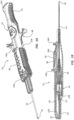
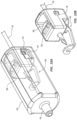
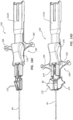
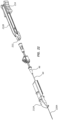
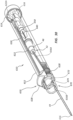
- FIGS. 1A-1B and 2A-2B depict various details regarding a catheter insertion tool ("insertion tool"), generally depicted at 10, according to one embodiment.
- the insertion tool 10 includes a housing 12 that in turn includes a top housing portion 12A separably mated with a bottom housing portion 12B.
- a needle hub 14 supporting a hollow needle 16 is interposed between the housing portions 12A and 12B.
- the needle 16 extends distally from the needle hub 14 so as to extend through the body of the insertion tool 10 and out a distal end of the housing 12.
- the needle is at least partially hollow while still enabling the functionality described herein.
- a notch 18 is defined through the wall of the needle 16 proximate the distal end thereof.
- the notch 18 enables flashback of blood to exit the lumen defined by the hollow needle 16 once access to the patient's vasculature is achieved during catheter insertion procedures.
- blood exiting the notch 18 can be viewed by a clinician to confirm proper needle placement in the vasculature, as will be explained further below.
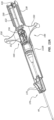
- the insertion tool 10 further includes a guidewire advancement assembly 20 for advancing a guidewire 22 through the needle 16 and into the vasculature of the patient once access by the needle has been achieved.
- the guidewire 22 is pre-disposed within the lumen of the needle 16, with a proximal end of the guidewire positioned proximate the proximal end of the needle hub 14, as best seen in FIGS. 1B and 2A .
- the guidewire advancement assembly 20 includes a guidewire lever 24 that selectively advances the guidewire in a distal direction during use of the insertion tool 10 such that the distal portion of the guidewire extends beyond the distal end of the needle 16.
- the guidewire lever 24 includes a lever tab 26 that engages the proximal end of the guidewire 22 so to push the guidewire through the lumen of the needle 16.
- the guidewire advancement assembly 20 further includes a slide 28 that is slidably attached to the top housing portion 12A.
- Two tabs 24A of the guidewire lever 24 operably attach to the slide 28 so that selective movement by a user of the slide results in corresponding movement of the lever 24, and by extension, the guidewire 22. Engagement of the lever tabs 24A to the slide 28 also maintains attachment of the slide to the housing 12.
- Suitable tracks are included in the top housing portion 12A to enable sliding movement of the slide 28 and the lever 24, including a track 34 extending to the distal end of the housing 12.
- the slide 28 includes two arms 30 that wrap partially about rails 32 defined by the housing 12.
- the arms 30 slide on a bottom housing rail 32A, best seen in FIG. 5B .
- the arms 30 slide past the bottom housing rail 32A and on to a top housing rail 32B, best seen in FIGS. 2A and 3A .
- the two housing portions 12A and 12B are able to separate, as will be described further below.
- the guidewire lever 24 includes a locking arm 36 resiliently disposed so as to spring up and engage an extension 36A defined in the interior of the top housing portion 12A when the slide 28 has been fully slid distally. This prevents inadvertent retraction of the guidewire 22 once distally extended, which could otherwise cause unintended severing of a distal portion of the guidewire by the distal tip of the needle 16 during insertion procedures. Note that engagement of the locking arm 36 with the extension 36A can provide tactile and/or audible feedback to the user in one embodiment so as to indicate full distal extension of the guidewire 22.
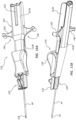
- the insertion tool 10 further includes a catheter advancement assembly 40 for selectively advancing in a distal direction a catheter 42, pre-disposed in the housing 12, and including a catheter tube 44 and a hub 46 at a proximal end thereof.
- a catheter advancement assembly 40 for selectively advancing in a distal direction a catheter 42, pre-disposed in the housing 12, and including a catheter tube 44 and a hub 46 at a proximal end thereof.
- the catheter 42 is partially and initially pre-disposed within a volume defined by the housing 12 such that the lumen of the catheter tube 44 is disposed over the needle 16, which in turn is disposed over the guidewire 22, as mentioned.
- the catheter advancement assembly 40 includes a handle 48 that defines a base 48A and two arms 50 extending from the handle base.
- Each arm 50 defines a grip surface 50A, finger grabs 50B, and one of two teeth 50C.
- the grip surfaces 50A and finger grabs 50B enable the handle to be grasped or contacted by a user in order to selectively advance the catheter 42 in a distal direction during use of the insertion tool 10 to insert the catheter into the body of the patient.
- the teeth 50C engage corresponding raised surfaces on the hub 46 so as to removably connect the handle 48 to the catheter 42.
- a plug, or valve 52 is interposed between the handle base 48A and the catheter hub 46 to prevent blood spillage when the catheter is first introduced into the patient vasculature.
- a safety housing 54 including a needle safety component 56 therein, is removably attached to the handle 48 between the arms 50. Specifically, protrusions 60 included on the inner surfaces of the handle arms 50 engage with corresponding recesses 62 ( FIG. 10A ) defined in the safety housing 54 to removably secure the safety housing to the handle 48.
- a cap 56 supports the needle safety component 56 and covers the end of the safety housing 54.
- the needle 16 initially extends through the aforementioned components in the order as shown in FIG. 2B . Further details regarding the operation of these components are given below.
- the outer diameters of the needle 16 and the catheter tube 44 are lubricated with silicone or other suitable lubricant to enhance sliding of the catheter tube with respect to the needle and for aiding in the insertion of the catheter into the body of the patient.
- the insertion tool 10 further includes a support structure 70 for stabilizing the needle 16 proximate its point of exit from the housing 12.
- the support structure 70 includes an interface 72 of the top housing portion 12A and bottom housing 12B that is shaped to closely match the round shape of the needle 16 and catheter tube 44.
- the interface 72 stabilizes the needle 16 so as to prevent excessive "play" in the needle, thus improving user accuracy when initially accessing the vasculature of the patient.
- the top housing 12A, the needle hub 14, and the bottom housing 12B include engagement features 68 to maintain attachment of the proximal end of the housing 12 even when more distal portions of the housing are separated, discussed below. Note, however, that various types, sizes, and numbers of engagement features can be employed to achieve this desired functionality.
- FIGS. 3A-9 depict various stages of use of the insertion tool 10 in placing the catheter 42 in the vasculature of a patient. For clarity, the various stages are depicted without actual insertion into a patient being shown.
- a user grasping the insertion tool 10 first guides the distal portion of the needle 16 through the skin at a suitable insertion site and accesses a subcutaneous vessel. Confirmation of proper vessel access having been achieved is evident via blood flash, i.e., the presence of blood between the outer diameter of the needle 16 and the inner diameter of the catheter tube 44 due to blood passing out the notch 18 from the hollow interior of the needle.
- the presence of blood in the safety housing 54 which in one embodiment is a translucent housing, can serve as a secondary blood flash indicator due to blood entering the housing from the needle 16 when the vessel is accessed.
- the guidewire advancement assembly 20 is actuated, wherein the slide 28 is advanced by the finger of the user to distally advance the guidewire 22 ( FIGS. 3A and 3B ), initially disposed within the hollow needle 16.
- the guidewire is distally advanced by the lever 24, which is operably attached to the slide 28.
- the slide arms 30 thereof travel along the rails 32 on either side of the housing 12: first the bottom housing rails 32A, then the top housing rails 32B.
- FIGS. 5A and 5B show that, upon full distal advancement of the slide 28, the slide arms 30 thereof are no longer engaged with the bottom housing rails 32A, but rather with only the top housing rails 32B. This in turn enables the housing portions 12A and 12B to separate, as seen further below.
- FIGS. 5A and 5B As seen in FIGS. 5A and 5B , once the guidewire 22 has been fully extended within the vessel of the patient ( FIGS. 4A and 4B ), the catheter advancement assembly 40 is actuated, wherein the handle 48 is distally advanced by the user to cause the catheter tube 44 to slide over distal portions of the needle 16 and guidewire 22 and into the patient's vasculature via the insertion site.
- FIGS. 6A and 6B show that, as the catheter is advanced via the handle 48, the housing portions 12A and 12B are easily separated so as to enable the catheter hub 46 to exit the distal end of the housing 12 and for the catheter to be inserted into the patient vasculature to a suitable degree.
- FIG. 8 shows that the insertion tool 10 can then be separated from the catheter 42, leaving the handle 48 still attached to the catheter hub 46.
- the handle 48 includes the valve 52 interposed between the catheter hub 46 and the handle 48. Upon removal of the needle 16 and safety housing 54 from the catheter 42, the valve 52 occludes the catheter lumen so as to prevent inadvertent blood spillage from the catheter hub 46. As shown in FIG.
- the handle 48 be removed from engagement with the catheter hub 46 via pulling, twisting, etc., so as to disengage the teeth 50C of the handle from the hub.
- An extension leg can be attached to the catheter hub and the catheter 42 dressed down, per standard procedures. Then housing 12 and handle 48 of the insertion tool 10 can be discarded.
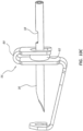
- FIGS. 1OA-IOC give further details regarding the safety housing 54, as well as the needle safety component 56 and its interaction with the needle 16 in isolating the distal end thereof.
- the safety housing 54 is configured to enable the needle 16 to pass therethrough during use of the insertion tool 10, as has been described, exiting the housing via the extension 74 on the distal end of the housing.
- the cap 58 is placed into the proximal end of the safety housing 54 and is configured to support the needle safety component 56 such that the needle 16 initially passes through the safety housing, the cap, and the needle safety component.
- the extension 74 of the safety housing 54 in the present embodiment extends into the valve 52 so as to open the valve during use of the insertion tool 10, which eliminates undesired friction between the valve and the needle.
- FIG. 10C shows that the needle safety component 56 includes a bent body, or binding element 80 through which the needle initially extends, and a friction element 82.
- the distal tip of the needle is withdrawn proximally through the extension 74 and past the distal portion of the needle safety component such that the needle is no longer in contact therewith.
- the friction element 82 to cause the binding element 80 to cant slightly, thus binding the needle 16 in place and preventing its further travel with respect to the safety housing 54 and isolating the needle distal tip within the housing so as to prevent inadvertent needle sticks.
- the friction element 82 includes a suitably sized O-ring.
- Suitable O-rings can be acquired from Apple Rubber Products, Lancaster, NY, for instance. Note that further details regarding the needle safety component, its operating principles, and similar devices are disclosed in U.S. Patent Nos. 6,595,955 , 6,796,962 , 6,902,546 , 7,179,244 , 7,611,485 , and 7,618,395 . Of course, other needle safety devices can be employed to isolate the distal end of the needle.
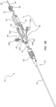
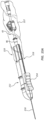
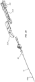
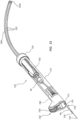
- FIGS. 11A-13B in describing a catheter insertion tool 110 according to one embodiment. Note that in this and succeeding embodiments, various features are similar to those already described in connection with the above embodiment. As such, only selected aspects of each embodiment to follow will be described.
- the insertion tool 110 includes a housing 112 defined by a top housing portion 112A and a bottom housing portion 112B that together partially enclose the catheter 42.
- a needle hub 114 supporting a distally extending needle 116 is included for disposal within the housing 112 and positioned such that the catheter tube 44 of the catheter 42 is disposed over the needle. Note that partial enclosure of the catheter by the insertion tool in this and other embodiments enables a clinician to manipulate the insertion tool with hands that are closer to the distal end of the needle than what would otherwise be possible.
- FIGS. 13A and 13B give further details regarding the needle hub 114, which is attached to the top housing portion 112A
- a needle holder 126 included on a distal end of the needle hub 114, receives the proximal end of the needle 116 therein.
- the needle 116 is secured within the needle holder 126 via adhesive, welding, or other suitable manner.
- Extensions 128 are included on opposite sides of the needle holder 126 and are configured to be slidably received within corresponding slots 130 defined on the sides of the bottom housing portion 112B. Such engagement enables the bottom housing portion 112B to slide distally with respect to the top housing portion 112A.
- a top rail 132 is included on the needle hub 114 and is configured to engage a corresponding slot 134 defined in the proximal portion of the top housing portion 112A so as to secure the needle hub to the top housing portion.
- a lock out arm 136 is also included with the needle hub 114 and positioned to engage the back plate 124 when the bottom housing portion 112B is slid distally to extend the guidewire from the needle 116, thus preventing its retraction. Note that the guidewire 122 initially distally extends from the back plate 124 and through the needle holder 126 and needle 116, as best seen in FIG. 11D .
- a guidewire advancement assembly 120 is included to selectively advance a guidewire 122, initially disposed within the lumen of the needle, distally past the distal end of the needle 116.
- the guidewire advancement assembly 120 includes the bottom housing portion 112B to which the guidewire 122 is attached at a proximal back plate 124 thereof. As will be seen, the bottom housing portion 112B is distally slidable with respect to the top housing portion 112A to enable selective distal advancement of the guidewire 122.
- the insertion tool 110 further includes a catheter advancement assembly 140 for selectively advancing the catheter 42 over the needle 116.
- the advancement assembly 140 includes a handle 146 initially and slidably disposed between the top and bottom housings 112A and112B and removably attached to the hub 46 of the catheter 42.
- the handle 146 includes two arms 150 for allowing a user to selectively slide the handle in order to advance the catheter 42.
- the handle 146 further includes a recess 152 in which is placed a needle safety component 156 for isolating the distal tip of the needle 116 when the needle is withdrawn from the catheter 42. Further details regarding the needle safety component are disclosed in U.S. Patent Nos. 6,595,955 , 6,796,962 , 6,902,546 , 7,179,244 , 7,611,485 , and 7,618,395 .
- the insertion tool 110 further includes a support structure 170 for stabilizing the needle 116 proximate the distal end of the housing 112.
- the support structure 170 in the present embodiment includes two flaps 172 that arc hingedly connected to the distal portion of the bottom housing portion 112B. When closed as seen in FIGS. 11D and 12A , the flaps 172 serve to stabilize the needle 116 to assist the user of the insertion tool 110 in inserting the needle into the patient. When open ( FIG. 14D ), the flaps 172 provide an opening to enable the catheter hub 46 to be removed from the distal end of the housing 112, as will be detailed further below.
- the insertion tool 110 further includes gripping surfaces 176 on either side of the housing 112 to aid in use of the tool during catheter insertion procedures, detailed below.
- FIGS. 14A-14E depict various stages of use of the insertion tool 110 in inserting a catheter into a patient.
- vascular access is achieved with the needle 116 via user insertion of the needle into the patient at an insertion site.
- Confirmation of vessel access can be achieved via the observation of blood flashback via a distal notch in the needle 116, as described in the previous embodiment, or in other suitable ways.
- the guidewire 122 is extended past the distal end of the needle and into the vessel by distally advancing the bottom housing portion 112B.
- Such advancement is achieved in the present embodiment by placing a user's fingers on the folded-up flaps 172 of the bottom housing portion 112B and pushing the flaps distally, thus extending the guidewire 122.
- the guidewire 122 is advanced until fully extended.
- the lock out arm 136 of the needle hub 114 then engages the back plate 124 of the bottom housing portion 112B and prevents retraction of the guidewire 122.
- the handle 146 of the catheter advancement assembly 140 is distally advanced, by a user grasping of one or both arms 150 thereof, so as to distally advance the catheter 42 through the insertion site and into the patient vasculature. This is shown in FIG. 14C , wherein the catheter tube 44 is shown distally advancing over the needle 116 and the guidewire122.
- FIG. 14E shows that, with the flaps no longer engaged within the track 174, the top housing portion 112A and bottom housing portion 112B are able to separate at the distal ends thereof such that the handle 146, still attached to the catheter hub 46, can separate from the housing 112.
- the needle safety component 156 disposed in the recess 152 of the handle 146 isolates the distal end of the needle 116.
- the handle 146 can then be manually removed from the catheter hub 46 ( FIG. 14F ), and placement and dressing of the catheter 42 can be completed.
- the insertion tool 110 including the needle 116 isolated by the needle safety component 156 of the handle 146, can be safely discarded.
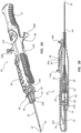
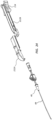
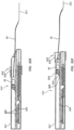
- the insertion tool 210 includes a housing 212 defined by a top housing portion 212A and a bottom housing portion 212B that together partially enclose the catheter 42.
- a sliding needle hub 214 supporting a distally extending hollow needle 216 is slidably attached to the housing 212.
- the needle hub 214 includes tracks 214A that slidably engage corresponding rails 218 defined on the top and bottom housing portions 212A, 212B in a manner described further below.
- the needle hub 214 is positioned distally with respect to the housing 212 such that the needle 216 extends through a needle channel 224 ( FIG. 18 ) and out a hole defined in a distal end of the top housing portion 212A so that the needle is positioned as shown in FIG. 15A .
- the housing 212 of the insertion tool 210 encloses a portion of the catheter 42.
- An integrated guidewire/dilator 220 is included and disposed within the lumen of the catheter tube 44, as shown in FIGS. 15B and 16 .
- the guidewire/dilator 220 includes a distal guidewire portion 220A and a proximal dilator portion 220B. So configured, the guidewire/dilator 220 can not only serve as a guidewire in directing the catheter tube 44 through the insertion site of the patient into the accessed vessel, but can dilate the insertion site in advance of catheter insertion therethrough. In other embodiment, no guidewire/dilator need be used.
- the guidewire/dilator 220 can proximally extend through the entire catheter 42 and include on a proximal end thereof a luer cap connectable to a proximal luer connector of the catheter.
- FIG. 15A shows a sterile bag 217 attached to the housing 212 so as to cover and isolate the proximal portion of the catheter 42.
- the bag 217 is included only in FIG. 15A , but could be included with insertion tools of varying configurations so as to protect and isolate portions of the catheter.
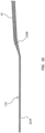
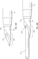
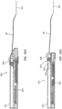
- the needle 216 includes a longitudinally extending needle slot 226 extending from a beginning point along the length of the needle to the distal end thereof.
- FIG. 17B shows that the slot 226 can be optionally wider in a proximal portion thereof relative to more distal slot portions. So configured, the needle slot 226 enables the guidewire/dilator 220 to be inserted into, slid relative to, and removed from the needle 216 during operation of the insertion tool 210, described below.
- the needle slot can extend the entire length of the needle, in one example.
- FIG. 18 shows the manner of entry of the guidewire/dilator 220 into the slot 226 of the needle 216 according to one example, wherein the guidewire/dilator extends distally along a guide channel 222 defined in the top housing portion 212A and into the hollow needle 216, which is disposed in the needle channel 224, via the needle slot.
- the guide channel 222 is also seen in FIG. 15B .
- the guidewire/dilator 220 can be distally slid through the hollow needle 216 so as to extend beyond the distal needle end while still being able to be removed from the needle via the slot 226 when the guidewire/dilator and needle are separated from one another, as will be seen.
- FIG. 18 also shows a support structure 270 for stabilizing the needle 216, including an interface 272 defined by portions of the top housing portion 212A and the bottom housing portion 212B about the hole through which the needle extends.
- a support structure 270 for stabilizing the needle 216 including an interface 272 defined by portions of the top housing portion 212A and the bottom housing portion 212B about the hole through which the needle extends.
- FIG. 19 shows details of a lockout 230 for the needle hub 214, included on the bottom housing portion 212B, for preventing further movement of the needle hub after it has been retracted, as described below.
- FIGS. 19-24 depict various stages of use of the insertion tool 210 in inserting a catheter into a patient.
- vascular access is achieved with the needle 216 via user insertion of the needle into the patient at an insertion site.
- the guidewire/dilator 220 is manually fed through the hollow needle 216 so as to extend past the distal end of the needle and into the vessel.
- Such advancement is achieved in the present embodiment by distally moving the housing 212 and catheter 42 together while keeping the needle hub 214 stationary.
- the guidewire 122 is advanced distally a suitable distance, which in the present example. includes advancement until a distal end of the housing 212 arrives at the skin insertion site.
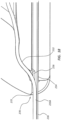
- FIGS. 20A and 20B show that after the guidewire/dilator 220 has been distally extended into the vessel, the needle 216 is retracted from the vessel by proximally sliding the needle hub 214 along rail portions 218A disposed on the top housing portion 212A. Proximal sliding of the needle hub 214 continues until the hub engages the rail portions 218B of the bottom housing portion 212B and is fully slid to the proximal end of the housing 212, as shown in FIGS. 2IA and 21B . The needle hub 214 engages the lock out 230 ( FIG. 20B ) so as to prevent future distal movement of the needle hub or needle 216.
- the needle 216 is fully retracted into the insertion tool housing 212 such that the distal end of the needle is safely isolated from the user ( FIG. 21B ).
- a needle safety component can be added to the insertion tool to further isolate the tip of the needle. Note that the distal portion of the guidewire/dilator 220 remains in the vessel of the patient, having been able to separate from the needle 216 during retraction thereof via the needle slot 226.
- the bottom housing portion 21213 ( FIG. 22 ) and the top housing portion 212A ( FIG. 23 ) are removed from the catheter 42.
- the catheter 42 can then be inserted through the insertion site and into the vessel of the patient.
- the guidewire/dilator 220 is still disposed within the catheter tube 44 and that the dilator portion assists the distal end of the catheter tube to enter the vessel by gradually enlarging the insertion site and the vessel entry point,
- the proximal portion of the catheter 42 is covered by a sterile bag, which is attached to the housing 212.
- the sterile bag can be removed after the catheter is fully inserted into the patient vessel or can be removed when the housing portions 212A and 212B are removed.
- the guidewire/dilator 220 is then removed from the catheter 42 and the catheter dressed and finalized for use. The guidewire/dilator 220 and other portions of the insertion tool 210 are discarded.
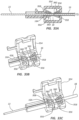
- FIGS. 25A and 25B depict details regarding a needle blunting system for isolating a distal end 316A of a hollow needle 316, according to one example.
- the needle distal end 316A includes a bevel that is configured such that its cutting surfaces are disposed at an inner diameter 318 of the needle 316.
- the cutting surfaces of the needle are blocked by the proximity thereto of the guidewire, thus safely isolating the needle end from a user.
- blunting the distal end 316A of the needle 316 in this manner prevent the needle end from damaging sensitive inner walls of the vessel after the needle tip has been inserted herein.
- FIG. 26 depicts a needle end bevel 316A according to another example, including an additional fillet component 319.
- a blunting system can be employed in one or more of the insertion tools described herein.
- the insertion tool 410 includes a housing 412 that partially encloses the catheter 42.
- a distally extending hollow needle 416 is disposed with the housing 412 such that the needle extends out the distal end of the housing 412
- a guidewire advancement assembly 420 is shown for selectively advancing a guidewire 422, including a slide 428 that slides along a track 430 defined in the housing 412.
- the guidewire 422 is attached to the slide 428 and extends proximally within the housing 412 until it bends, forming a guidewire bend 422A, toward the distal end of the housing and passes into the hollow needle 416 via a proximal end 416A thereof for selective distal advancement past the distal end of the needle via user actuation of the slide.
- Distal advancement of the guidewire 422 out the distal end of the needle 416 is stopped when the guidewire bend 422A engages the needle proximal end 416A.
- a catheter advancement assembly 440 is also shown for selectively advancing the catheter tube 44 over the needle 416, including a slide 448 that slides along the track 430, and a carriage 450 disposed within the housing 412 and operably connected to the slide 448.
- the carriage 450 is initially engaged with the catheter hub 46 such that distal sliding of the slide 448 causes the catheter to be distally advanced toward the distal housing end.
- the insertion tool 410 further includes a support structure 470 for stabilizing the needle 416, including two doors 472 hingedly attached via pins to the distal end of the housing 412.
- the doors 472 serve to stabilize the needle 416 during insertion into the patient. Later, when the catheter tube 44 and catheter hub 46 are advanced distally by the slide 448, the doors 472 are opened, enabling the catheter 42 to pass through the doors and be separated by the user from the insertion tool 410.
- a wedge feature is included on the bottom surface of the slide 428, the wedge feature being configured to push the doors 472 open when the slide is slid distally, as described herein. Such a wedge or other suitable feature can be included in other embodiments described herein as well.
- the catheter 42 can then be advanced and placed as needed into the patient by the user.
- a needle safety component can be included for isolating the distal tip of the needle 416.
- distal sliding of the guidewire slide 428 can partially open the doors 472 in preparation for catheter advancement.
- FIG. 28 shows the insertion tool 410 including a support structure 480 according to another example, wherein two half-conically shaped doors 482 are hingedly connected to the housing 412 (via living hinges or other suitable connective scheme) and configured to stabilize the needle 416.
- the carriage of the insertion tool 410 in FIG. 28 is also longer relative to that of FIG. 27 .
- various different support structures and configurations can be employed for stabilizing the needle at or near its exit point from the insertion tool housing.
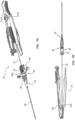
- the insertion tool 510 includes a housing 512 that partially encloses the catheter 42.
- a hollow needle 516 distally extends from a needle hub 514 that caps a proximal end of the housing 512 such that the needle extends out the distal end of the housing 512.
- a guidewire advancement assembly 520 is shown for selectively advancing a guidewire 522, including a slide 528 that slides along a track 530 defined in the housing 512.
- the guidewire 522 is attached to the slide 528 and extends proximally within the housing 512 and out through a pigtail 524, attached to the proximal end of the housing 512, via a top one of two holes 514A defined in the needle hub 514.
- the guidewire 522 bends to form a U-shaped guidewire bend 522A and distally extends back into the housing 512 to pass into the hollow needle 516 via a bottom one of the two needle hub holes 514A, for eventual distal advancement out the distal end of the needle when the slide 528 is selectively actuated by a user.
- Such distal advancement of the guidewire 522 out the distal end of the needle 416 is stopped when the guidewire bend 522A abuts the holes 5 14A defined in the needle hub 514.
- a catheter advancement assembly 540 is also shown for selectively advancing the catheter tube 44 over the needle 516, including a slide 548 that slides along the track 530, and a carriage 550 disposed within the housing 512 and operably connected to the slide.
- the carriage 550 can be initially engaged with the catheter hub 46 such that distal sliding of the slide 548 causes the catheter to be distally advanced toward the distal housing end.
- a bulge 522B is included on the guidewire 522 such that, when the guidewire is distally advanced by user actuation of the (guidewire advancement) slide 528, the bulge is advanced and engages an internal portion of the (catheter advancement) slide 548. This in turn causes the slide 548 to be advanced as well, resulting in distal advancement of the catheter 42.
- the catheter can be advanced directly via the slide 548, or indirectly via the slide 528, in one example.
- the insertion tool 510 further includes a support structure 570 for stabilizing the needle 516, including a plug 572 that includes a plug hole 574 defined therein through which the needle 516 extends.
- the plug 572 is attached via the track 530 to the slide 528 and occludes the distal end of the housing 512, thus serving to stabilize the needle 516 that passes therethrough during needle insertion into the patient. Later, when the guidewire 522 is advanced distally by the slide 528, the plug 572 also distally advances out the housing 512, thus opening the housing distal end and enabling the catheter 42 to pass therethrough. The catheter 42 can then be separated by the user from the insertion tool 5 10 and advanced into final position by the user.
- a needle safety component can be included for isolating the distal tip of the needle 516. Note also that after the plug 572 is removed from its initial position in the housing 512, the catheter tube 44 and needle 516, no longer being constrained by the support structure plug hole 574, can axially relocate toward the center of the housing, in one example. This holds true for the examples of FIGS. 30 and 31 as well.
- the insertion tool 610 includes a housing 612 that partially encloses the catheter 42.
- a hollow needle 616 distally extends from a needle hub 614 that caps a proximal end of the housing 612 such that the needle extends out the distal end of the housing 612.
- the needle 616 includes a longitudinally extending proximal slot 616A that extends from the proximal end of the needle 616 to a distal end 616B of the slot.
- a guidewire advancement assembly 620 is shown for selectively advancing a guidewire 622, including a slide 628 that slides along a track 630 defined in the housing 612,
- the guidewire 622 is attached to the slide 628 and extends proximally within the housing 612 until it bends, forming a U-shaped guidewire bend 622A, toward the distal end of the housing and passes into the hollow needle 616 via the proximal slot 616A thereof for selective distal advancement past the distal end of the needle via user actuation of the slide.
- distal advancement of the slide 628 causes the slide to separate from the housing 612 while still being attached to the guidewire 622.
- Distal advancement of the guidewire 622 out the distal end of the needle 616 is stopped when the guidewire bend 622A engages the distal end 616B of the proximal slot 616A of the needle.
- a catheter advancement assembly 640 is also shown for selectively advancing the catheter tube 44 over the needle 616, including a carriage 650 disposed within the housing 612 and operably connected to the slide 628 such that actuation of the slide distally advances both the guidewire 622 and the carriage 650.
- the carriage 650 is not initially engaged with the catheter hub 46, but engages the hub after an amount of distal advancement. This in turn causes the catheter 42 to be distally advanced toward the distal housing end.
- the insertion tool 610 further includes a support structure 670 for stabilizing the needle 616, including a plug 672 that includes a plug hole 674 defined therein through which the needle 616 extends.
- the plug 672 is attached via the track 630 to the slide 628 and occludes the distal end of the housing 612, thus serving to stabilize the needle 616 that passes therethrough during needle insertion into the patient. Later, when the guidewire 622 is advanced distally by the slide 628, the plug 672 also distally advances out the housing 612, thus opening the housing distal end and enabling the catheter 42 to pass therethrough.
- the catheter 42 can then be separated by the user from the insertion tool 610 and advanced into final position by the user.
- the carriage 650 can include a needle safety component for isolating the distal end of the needle 616.
- the insertion tool 710 includes a housing 712 that partially encloses the catheter 42.
- a hollow needle 716 distally extends from a needle hub 714 that caps a proximal end of the housing 712 such that the needle extends out the distal end of the housing 712.
- An advancement assembly 720 is shown for selectively advancing a guidewire 722 and catheter 42.
- the advancement assembly 720 includes a wheel 730, selectively rotatable by a user, that is attached via a filament 726 or other suitable component to a carriage 750.
- the guidewire 722 is attached to the carriage 750 and extends proximally within the housing 712 and out through a pigtail 724, attached to the proximal end of the housing 712, via a one of two holes defined in the needle hub 514 (similar to the holes 514A in the needle hub 514 of FIGS.
- the guidewire 722 bends to form a U-shaped guidewire bend 722A and distally extends back into the housing 712 to pass into the hollow needle 716 via the other of the two holes defined in the needle hub 714 for eventual distal advancement out the distal end of the needle when the wheel 730 is selectively actuated by a user.
- Such distal advancement of the guidewire 722 out the distal end of the needle 716 is stopped when the guidewire bend 722A abuts the above-mentioned holes defined in the needle hub 714.
- the advancement assembly 720 selectively advances the catheter tube 44 over the needle 716 and includes the aforementioned carriage 750 disposed within the housing 712 and operably connected to the wheel 730 via the filament 726 such that rotation of the wheel distally advances the carriage 750.
- the guidewire 722, a proximal end of which being attached to the carriage 750, is also advanced distally through the needle, as described above. Note that in one example the wheel 730, by virtue of the non-rigid filament 726 connecting the wheel to the carriage 750, ensures that the guidewire 722 is only distally advanced, and not proximally retractable.
- Distal advancement of the carriage 750 causes the carriage - which is not initially engaged with the catheter hub 46 on to engage the hub after an amount of distal advancement. This in turn causes the catheter 42 to be distally advanced toward the distal housing end.
- the insertion tool 710 further includes a support structure 770 for stabilizing the needle 716, including a door 772 hingedly attached to the distal end of the housing 712 and including a hole 774 therein for enabling passage of the needle 716 therethrough.
- the door 772 serves to stabilize the needle 716 during insertion into the patient. Later, when the catheter tube 44 and catheter hub 46 are advanced distally by the wheel 730 and the carriage 750, the door 772 is pushed open by the hub, enabling the catheter 42 to be separated by the user from the insertion tool 710. The catheter 42 can then be advanced for final placement within the patient by the user. Note that, though none is shown, a needle safety component can be included for isolating the distal tip of the needle 716.
- the insertion tool 10 includes a housing 812 that at least partially encloses the catheter 42.
- a hollow needle 816 distally extends from a needle hub 814 included within the housing 812 such that the needle initially extends out the distal end of the housing 812.
- the needle 816 includes a distal slot 816A, similar to the previously described needle slot 226 ( FIGS. 17A-17C ), for enabling a guidewire/dilator 822, similar to the previously described guidewire/dilator 220 ( FIG. 16 ) to be removably inserted therein.
- the catheter 42 is disposed over the guidewire/dilator 822.
- the needle hub 814 further includes a needle retraction system 818 for selectively retracting the needle 816 into the housing 812 so as to isolate the distal tip of the needle from the user in a safe manner.
- the retraction system 818 includes a spring 819 or other suitable retraction device operably coupled to the needle 816 for effecting the needle retraction.
- An advancement assembly 820 is shown for selectively advancing the guidewire/dilator 822 as well as the catheter 42.
- the advancement assembly 820 includes a slide 828 that travels in a track 830 defined in the housing 812.
- the slide 828 is operably attached to a ratchet bar 824 slidably disposed within the housing 812.
- the ratchet bar 824 includes a plurality of upper teeth 826 for selective catheter advancement, and at least one lower tooth 826A for actuating a retraction trigger 880 of the needle retraction system 818, as will be described.
- the hub 46 of the catheter 42 disposed within the housing 812 has removably attached thereto a cap 834 including a prong 836 for engaging the upper teeth 826 of the ratchet bar 824.
- the insertion tool 810 further includes a support structure 870 for stabilizing the needle 816, including a housing hole 872 defined by the distal end of the housing 812.
- the housing hole 872 is sized to provide stability to the needle 816 at its point of exit from the housing.
- FIGS. 32A-32I depict various stages of use of the insertion tool 810 in inserting a catheter into a patient.
- vascular access is achieved with the needle 816 via user insertion of the needle into the patient at an insertion site.
- Blood flashback can be observed via the distal slot 816A of the needle 816 to confirm proper positioning of the distal end of the needle within the patient's vessel.
- the slide 828 is slid distally to advance the guidewire/dilator 822, a distal portion of which is pre-disposed within the needle 816 via the distal slot 816A, distally out the distal end of the needle and into the vessel of the patient.
- the guidewire/dilator 822 is advanced indirectly by the ratchet bar 824, which is moved by the slide 828.
- a proximate one of the upper teeth 826 of the ratchet bar 824 engages the prong 836 of the cap 834 fitted over the catheter hub 46.
- the catheter 42 and guidewire/dilator 822 disposed therein are also moved distally, as shown in FIG. 32B . Similar ratcheting movement occurs in the successive steps as well.
- FIG. 32C shows the return of the slide 828 to its initial position, which causes the ratchet bar 824 to also return to its initial position. Because the prong 836 of the cap 834 attached to the catheter hub 46 is distally angled, however, the teeth 826 of the ratchet bar slide past without retracting the catheter 42 such that the catheter remains in position.
- the slide 828 is again distally advanced, which causes a proximate upper tooth 826 of the ratchet bar 824 to engage the cap prong 836 and further advance the guidewire/dilator 822 distally into the vessel.
- the catheter 42 at this or a successive stage is also advanced into the vessel, depending on catheter length, distance to insertion site, etc.
- the slide 828 is subsequently retracted to its initial position, as shown in FIG. 32E .
- ratchet retraction can be user activated or automatically activated by a suitable system included in the insertion tool 810.
- FIG. 32F the slide 828 and ratchet bar 824 are again distally advanced, resulting in further distal advancement out of the housing 812 of the guidewire/dilator 822 and catheter 42.
- the slide 828 is subsequently retracted to its initial position, as shown in FIG. 32G .
- FIG. 32H the slide 828 and ratchet bar 824 are distally advanced a final time, resulting in near-complete distal advancement of the guidewire/dilator 822 and attached catheter 42 from the housing 812 of the insertion tool 810.
- the hub 46 of the catheter 42 can be grasped and the catheter removed from the insertion tool 810, which can then be discarded. Final positioning of the catheter 43 within the vessel can then be manually performed by the user.
- the cap 834 is also removed from the catheter hub 46.
- FIGS. 33A-33C depict details of a needle safety component for isolating the distal end 16A of the needle 16, the needle including the distal notch 18 as discussed above in connection with FIGS. 1A-10C , according to one embodiment.
- a safety housing 954 including a hinged door is included so as to ride over the needle 16.
- Two needle safety components 956 are oppositely disposed within the safety housing 954 and each also rides over the needle 16.
- Each needle safety component includes a base 958 defining a hole through which the needle 16 passes and a plurality of arms 960. The arms 960 extend from the base 958 and converge toward one another in conical fashion such that an end of each arm abuts the needle surface.
- the arms 960 are configured to engage the notch 18 defined in the distal portion of the needle 16 and prevent further movement of the needle 16 with respect to the needle safety component 956.
- each arm 960 compressively engages the outer surface of the needle 16 such that when one of the arms encounters the needle notch 18, the arm will descend into the notch slightly so as to lock the needle 16 in place with respect to the needle safety component 956.
- Two needle safety components 956 are disposed in the safety housing 954 so as to prevent further needle movement in either direction, distally or proximally.
- the distal end 16A of the needle 16 is safely isolated within the safety housing 954, as seen in FIGS. 33A-33C .
- the needle safety component described here is useful for isolating a needle even when the guidewire 22 still extends therethrough, as seen in FIG. 33C , for example.
- only one needle safety component as described above may be used.
- the needle safety component described here serves as one example of a variety of needle safety components that may be employed in connection with the present disclosure.
- the insertion tool can include a sterile sheath or bag that is disposed over a distal portion of the catheter that distally extends from the insertion tool housing so as to isolate the catheter.
- the needle pre-disposed within the catheter and retractable into the insertion tool housing, can extend from the bag to gain vascular access. Thereafter, the bag can be compressed toward the housing as the catheter is advanced into the vasculature, then disposed of once the catheter is fully inserted.
- the bag can include a grip wing or other device that helps to grasp the catheter or needle through the bag during insertion.
- the insertion tools described herein can include a cap or other protective device that is removably attached to the insertion tool before use so as to preserve the sterility of the needle and catheter.
Landscapes
- Health & Medical Sciences (AREA)
- Life Sciences & Earth Sciences (AREA)
- Biophysics (AREA)
- Pulmonology (AREA)
- Engineering & Computer Science (AREA)
- Anesthesiology (AREA)
- Biomedical Technology (AREA)
- Heart & Thoracic Surgery (AREA)
- Hematology (AREA)
- Animal Behavior & Ethology (AREA)
- General Health & Medical Sciences (AREA)
- Public Health (AREA)
- Veterinary Medicine (AREA)
- Media Introduction/Drainage Providing Device (AREA)
- Infusion, Injection, And Reservoir Apparatuses (AREA)
Claims (15)
- Einführungswerkzeug zum Einführen eines Katheters in einen Körper eines Patienten, umfassend: ein Gehäuse (12), in dem zumindest ein Abschnitt des Katheters (42) anfänglich angeordnet ist;eine zumindest teilweise hohle Nadel (16), die sich distal aus dem Gehäuse erstreckt, wobei zumindest ein Abschnitt des Katheters im Voraus über der Nadel angeordnet ist;einen Führungsdraht (22), der im Voraus innerhalb der Nadel angeordnet ist; und eine Vorschubanordnung (20) zum selektiven Vorschieben des Führungsdrahts distal über ein distales Ende der Nadel hinaus zur Vorbereitung für distales Vorschieben des Katheters,wobei das Gehäuse einen oberen Gehäuseabschnitt (12A) und einen unteren Gehäuseabschnitt (12B) einschließt, die getrennt aneinander befestigt sind, wobei die Führungsdraht-Vorschubanordnung einen benutzerbetätigten Schieber einschließt, und wobei distales Schieben des Schiebers mindestens teilweise Trennung des oberen und unteren Gehäuseabschnitts ermöglicht.
- Einführungswerkzeug nach Anspruch 1, wobei die Vorschubanordnung mindestens einen benutzerbewegbaren Aktuator (28) einschließt, wobei der Aktuator bevorzugt auch mindestens einen Abschnitt des Katheters über ein distales Ende der Nadel hinaus in entweder einer abgestuften Weise oder in Übereinstimmung mit dem distalen Vorschieben des Führungsdrahts vorschiebt, wobei ein distales Ende des Führungsdrahts in Bezug auf ein distales Ende des Katheters versetzt ist.
- Einführungswerkzeug nach Anspruch 1 oder 2, wobei die Vorschubanordnung eine Führungsdraht-Vorschubanordnung (20) und eine Katheter-Vorschubanordnung (40) einschließt, wobei jede Vorschubanordnung bevorzugt einen Aktuator einschließt,wobei die Katheter-Vorschubanordnung (40) bevorzugt einen Griff (48) einschließt, der anfänglich und abnehmbar an einer Muffe des Katheters innerhalb des Gehäuses befestigt ist, wobei distale Bewegung des Griffs den Katheter distal von dem Gehäuse distal bewegt, und wobei der Griff eine Nadelsicherheitskomponente (56) zum Isolieren einer distalen Spitze der Nadel einschließt, wenn die Nadel von dem Katheter entfernt wird,wobei die Nadelsicherheitskomponente bevorzugt die distale Spitze der Nadel mechanisch isoliert.
- Einführungswerkzeug nach einem der Ansprüche 1-3, wobei eine distale Spitze der hohlen Nadel eine Schneidfläche einschließt, die an einem Außendurchmesser des Nadellumens so angeordnet ist, dass sich ein Führungsdraht, der sich distal über die distale Spitze der Nadel hinaus erstreckt, dazu dient, die Schneidfläche von einem Benutzer zu isolieren.
- Einführungswerkzeug nach einem der Ansprüche 1-4, wobei es das Gehäuse einem Benutzer ermöglicht, das Gehäuse in der Nähe eines Austrittpunkts der Nadel von einem distalen Ende des Gehäuses zu ergreifen, und wobei ein Aktuator der Vorschubanordnung mindestens eines von einem Schieber, einem Rad und einem Sperrklinkenmechanismus einschließt.
- Einführungswerkzeug nach einem der Ansprüche 1-5, wobei der obere Gehäuseabschnitt (12A) und der untere Gehäuseabschnitt (12A) trennbar sind, um Entfernen des Katheters aus dem Gehäuse zu ermöglichen.
- Einführungswerkzeug nach einem der Ansprüche 1-6, weiter umfassend eine Nadelstützstruktur (70) zum Stabilisieren eines Abschnitts der Nadel, die sich distal von dem Gehäuse erstreckt, wobei die Nadelstützstruktur bevorzugt mindestens eines von einem Abschnitt des Gehäuses, einer mit dem Gehäuse gelenkig verbundenen Komponente und einem abnehmbaren Pfropfen einschließt.
- Einführungswerkzeug nach einem der Ansprüche 1-7, weiter umfassend eine Verriegelungskomponente (136), die proximale Bewegung des Führungsdrahts verhindert, nachdem der Führungsdraht distal vorgeschoben wurde.
- Einführungswerkzeug nach einem der Ansprüche 1-8:wobei distales Vorschieben des Führungsdrahts durch Eingreifen eines Abschnitts des Führungsdrahts in einen geschlitzten Abschnitt der Nadel angehalten wird; und/oder wobei die Nadel nach Verwendung in das Gehäuse zurückziehbar ist; und/oderwobei die Nadel weiter eine Kerbe (18) in der Nähe eines distalen Endes der Nadel einschließt, wobei die Kerbe Beobachten von Blutrückfluss ermöglicht.
- Einführungswerkzeug nach einem der Ansprüche 1-9, wobei der benutzerbetätigte Schieber gleitend an dem oberen Gehäuse befestigt ist.
- Einführungswerkzeug nach einem der Ansprüche 1-10:wobei der Schieber der Führungsdraht-Vorschubanordnung über eine Schiene gleitbar an mindestens einem des oberen und des unteren Gehäuseabschnitts befestigt ist, wobei der Schieber über einen Hebel betriebsfähig an dem Führungsdraht befestigt ist, wobei der Hebel weiter eine Verriegelungslasche zum Verhindern von Zurückziehen des Schiebers nach distalem Vorschieben des Führungsdrahts einschließt; oderwobei die Vorschubanordnung eine Katheter-Vorschubanordnung einschließt, die einen Griff einschließt, der gleitbar zwischen dem oberen und unteren Gehäuseabschnitt angeordnet ist und gleitbar ist, um den Katheter distal so vorzuschieben, dass sich der Katheter und der Griff von der Nadel und dem Gehäuse des Einführungswerkzeugs trennen können,wobei das Werkzeug bevorzugt eine Stützstruktur umfasst, die eine von dem oberen und unteren Gehäuse definierte Schnittstelle in der Nähe zum Abschnitt der Nadel, der sich von dem Gehäuse distal erstreckt, einschließt, wobei der Griff der Katheter-Vorschubanordnung bevorzugt eine Nadelsicherheitskomponente zum Isolieren einer distalen Spitze der Nadel einschließt, und wobei der Griff bevorzugt weiter ein Blutsteuerungsventil einschließt.
- Einführungswerkzeug nach einem der Ansprüche 1-11, wobei der Katheter einen Katheterschlauch (44) und eine Muffe (46) einschließt, wobei die Muffe und ein proximaler Abschnitt des Katheterschlauchs anfänglich in dem Gehäuse des Einführungswerkzeugs angeordnet sind.
- Einführungswerkzeug nach einem der Ansprüche 1-12, wobei dasGehäuse einen oberen Gehäuseabschnitt einschließt, der gleitbar in einen unteren Gehäuseabschnitt eingreift, wobei das Gehäuse darin angeordnet mindestens eine Muffe und einen proximalen Abschnitt eines Katheterschlauchs des Katheters aufweist; wobeidie Nadel an dem oberen Gehäuseabschnitt befestigt ist und sich distal von dem Gehäuse erstreckt, wobei die Nadel durch ein Lumen des Katheters durchgeht; wobeider Führungsdraht an dem unteren Gehäuseabschnitt befestigt ist und innerhalb der Nadel angeordnet ist, wobei in der Vorschubanordnung der untere Gehäuseabschnitt in Bezug auf den oberen Gehäuseabschnitt gleitbar ist, um distales Vorschieben des Führungsdrahts bis über die distale Spitze der Nadel hinaus zu ermöglichen, wenn der untere Gehäuseabschnitt selektiv distal bewegt wird;
und ein Kathetervorschubgriff betriebsfähig an dem Katheter befestigt ist und konfiguriert ist zum distalen Vorschieben des Katheters über die Nadel nach distaler Ausdehnung des Führungsdrahts, um einen Abschnitt des Katheters innerhalb des Körpers des Patienten einzuführen,und, wobei optional ein proximales Ende der Nadel in einer Nadelmuffe (14) montiert ist, wobei die Nadelmuffe an dem oberen Gehäuseabschnitt befestigt ist, wobei die Nadelmuffe Erweiterungen einschließt, die in im unteren Gehäuseabschnitt definierten Schlitzen gleitbar angeordnet sind für distale Bewegung des unteren Gehäuseabschnitts in Bezug auf den oberen Gehäuseabschnitt zum distalen Vorschieben des Führungsdrahts, und wobeidie Stützstruktur weiter optional erste und zweite Klappen einschließt, die an dem unteren Gehäuseabschnitt gelenkig befestigt sind, wobei jede Klappe in einer im oberen Gehäuseabschnitt definierten Spur aufgenommen wird, bevor der Führungsdraht distal vorgeschoben wird, sodass die Klappen die Nadel stabilisieren, wobei die Klappen zum Öffnen fähig sind, nachdem der Führungsdraht und der Katheter distal vorgeschoben wurden, um Trennen des Katheters von dem Gehäuse zu ermöglichen,wobei die ersten und zweiten Klappen bevorzugt weiter einen benutzerbetätigten Schieber zum distalen Vorschieben des Führungsdrahts definieren. - Einführungswerkzeug nach einem der Ansprüche 1-12, wobei eine Nadelmuffe gleitbar in das Gehäuse eingreift; wobeidie mindestens teilweise hohle Nadel an der Nadelmuffe befestigt ist und so konfiguriert ist, dass sie sich anfänglich von einer distalen Öffnung des Gehäuses erstreckt, wobei die Nadel einen Schlitz einschließt, der sich um einen vorbestimmten Abstand von dem distalen Ende davon proximal erstreckt; wobei derFührungsdraht einen proximalen Abschnitt einschließt, der im Voraus innerhalb des Katheters angeordnet wurde, und einen distalen Abschnitt, der im Voraus über den Schlitz davon innerhalb der Nadel angeordnet wurde, wobei derFührungsdraht distal vorgeschoben werden kann, um sich über das distale Ende der Nadel zu erstrecken, nachdem die Nadel in einen Patienten eingeführt wurde, und wobei der Katheter distal über den Führungsdraht in den Patienten vorgeschoben werden kann, nachdem die Nadel aus dem Patienten zurückgezogen wurde.
- Einführungswerkzeug nach Anspruch 14:
wobei der Schlitz der Nadel in der Breite entlang einer Länge davon variiert, und wobei der proximale Abschnitt des Führungsdrahts einen integrierten Dilatatorabschnitt mit einem größeren Durchmesser als der Durchmesser des distalen Abschnitts des Führungsdrahts einschließt; oderwobei die Nadelmuffe so konfiguriert ist, dass proximales Gleiten der Nadelmuffe die Nadel in das Gehäuse zurückzieht und es ermöglicht, dass sich der obere und untere Gehäuseabschnitt voneinander so trennen, dass der Katheter aus dem Gehäuse entfernt werden kann; oderwobei ein Führungskanal im unteren Gehäuseabschnitt definiert ist, um einen Übergang von dem distalen Abschnitt des Führungsdrahts von dem unteren Gehäuseabschnitt über den Nadelschlitz in die hohle Nadel bereitzustellen;wobei mindestens ein Abschnitt des Schlitzes der Nadel so dimensioniert ist, dass er Entfernen des Führungsdrahts daraus zulässt, wenn die Nadel durch die Nadelmuffe zurückgezogen wird, und wobei ein steriler Beutel über mindestens einem Abschnitt des Katheters angeordnet ist.
Applications Claiming Priority (7)
| Application Number | Priority Date | Filing Date | Title |
|---|---|---|---|
| US34500510P | 2010-05-14 | 2010-05-14 | |
| US34502210P | 2010-05-14 | 2010-05-14 | |
| US37205010P | 2010-08-09 | 2010-08-09 | |
| US38584410P | 2010-09-23 | 2010-09-23 | |
| US41524810P | 2010-11-18 | 2010-11-18 | |
| EP11781384.0A EP2569046B1 (de) | 2010-05-14 | 2011-05-13 | Katheterplatzierungsvorrichtung und -verfahren |
| PCT/US2011/036530 WO2011143621A1 (en) | 2010-05-14 | 2011-05-13 | Catheter placement device and method |
Related Parent Applications (1)
| Application Number | Title | Priority Date | Filing Date |
|---|---|---|---|
| EP11781384.0A Division EP2569046B1 (de) | 2010-05-14 | 2011-05-13 | Katheterplatzierungsvorrichtung und -verfahren |
Publications (3)
| Publication Number | Publication Date |
|---|---|
| EP3473291A1 EP3473291A1 (de) | 2019-04-24 |
| EP3473291B1 true EP3473291B1 (de) | 2024-09-11 |
| EP3473291C0 EP3473291C0 (de) | 2024-09-11 |
Family
ID=44914738
Family Applications (2)
| Application Number | Title | Priority Date | Filing Date |
|---|---|---|---|
| EP18210204.6A Active EP3473291B1 (de) | 2010-05-14 | 2011-05-13 | Katheterplatzierungsvorrichtung |
| EP11781384.0A Active EP2569046B1 (de) | 2010-05-14 | 2011-05-13 | Katheterplatzierungsvorrichtung und -verfahren |
Family Applications After (1)
| Application Number | Title | Priority Date | Filing Date |
|---|---|---|---|
| EP11781384.0A Active EP2569046B1 (de) | 2010-05-14 | 2011-05-13 | Katheterplatzierungsvorrichtung und -verfahren |
Country Status (8)
| Country | Link |
|---|---|
| EP (2) | EP3473291B1 (de) |
| JP (4) | JP6243735B2 (de) |
| CN (2) | CN104689456B (de) |
| BR (1) | BR112012029024B1 (de) |
| CA (1) | CA2799360C (de) |
| ES (2) | ES2989183T3 (de) |
| MX (1) | MX341401B (de) |
| WO (1) | WO2011143621A1 (de) |
Families Citing this family (100)
| Publication number | Priority date | Publication date | Assignee | Title |
|---|---|---|---|---|
| WO2007006055A2 (en) | 2005-07-06 | 2007-01-11 | Vascular Pathways Inc. | Intravenous catheter insertion device and method of use |
| ATE489989T1 (de) | 2007-05-07 | 2010-12-15 | Vascular Pathways Inc | Einführung eines intravenösen katheters und blutentnahmevorrichtung und anwendungsverfahren |
| US8932258B2 (en) | 2010-05-14 | 2015-01-13 | C. R. Bard, Inc. | Catheter placement device and method |
| US9872971B2 (en) | 2010-05-14 | 2018-01-23 | C. R. Bard, Inc. | Guidewire extension system for a catheter placement device |
| US11925779B2 (en) | 2010-05-14 | 2024-03-12 | C. R. Bard, Inc. | Catheter insertion device including top-mounted advancement components |
| US10384039B2 (en) | 2010-05-14 | 2019-08-20 | C. R. Bard, Inc. | Catheter insertion device including top-mounted advancement components |
| US9950139B2 (en) | 2010-05-14 | 2018-04-24 | C. R. Bard, Inc. | Catheter placement device including guidewire and catheter control elements |
| US8690833B2 (en) | 2011-01-31 | 2014-04-08 | Vascular Pathways, Inc. | Intravenous catheter and insertion device with reduced blood spatter |
| US9095683B2 (en) | 2011-02-25 | 2015-08-04 | C. R. Bard, Inc. | Medical component insertion device including a retractable needle |
| USD903101S1 (en) | 2011-05-13 | 2020-11-24 | C. R. Bard, Inc. | Catheter |
| US20130131597A1 (en) * | 2011-11-18 | 2013-05-23 | Michael Blaivas | Cartridge for a blood vessel access system and device |
| EP2745869A1 (de) | 2012-12-21 | 2014-06-25 | ECP Entwicklungsgesellschaft mbH | Schleusenanordnung für die Einführung eines strangförmigen Körpers, insbesondere eines Katheters, in einen Patientenkörper |
| US9522254B2 (en) | 2013-01-30 | 2016-12-20 | Vascular Pathways, Inc. | Systems and methods for venipuncture and catheter placement |
| EP2961460B1 (de) * | 2013-03-01 | 2019-07-10 | C.R. Bard, Inc. | Führungsdrahtverlängerungssystem für eine katheterplatzierungsvorrichtung |
| US9717886B2 (en) | 2013-03-12 | 2017-08-01 | Teleflex Medical Incorporated | Safety clip for a needle |
| US10357635B2 (en) | 2013-03-12 | 2019-07-23 | Teleflex Medical Incorporated | Catheter insertion device |
| US11224724B2 (en) | 2013-03-12 | 2022-01-18 | Teleflex Medical Incorporated | Catheter insertion device |
| CN104043181B (zh) * | 2013-03-15 | 2017-04-12 | B.布劳恩梅尔松根股份公司 | 带有密封件的安全iv导管组件 |
| CN105246536B (zh) * | 2013-04-05 | 2018-09-21 | J·J·加尔加诺 | 带有分段式稳定系统的导管组件 |
| CN105120938B (zh) * | 2013-06-12 | 2018-10-23 | 泰尔茂株式会社 | 导管组装体 |
| CN110115797B (zh) * | 2013-08-14 | 2022-05-27 | 泰利福医疗公司 | 导管插入器械 |
| US9205229B2 (en) | 2013-10-24 | 2015-12-08 | Avent, Inc. | Catheter advancement device |
| WO2015115316A1 (ja) | 2014-01-29 | 2015-08-06 | テルモ株式会社 | カテーテル組立体 |
| WO2015115315A1 (ja) * | 2014-01-29 | 2015-08-06 | テルモ株式会社 | カテーテル組立体 |
| CN106456879B (zh) * | 2014-05-02 | 2020-06-30 | 巴德阿克塞斯系统股份有限公司 | 包括导丝和导管控制元件的导管放置装置 |
| EP3169378B1 (de) | 2014-08-26 | 2021-09-29 | C.R. Bard Inc. | Harngangkatheter |
| WO2016037127A1 (en) | 2014-09-05 | 2016-03-10 | C.R. Bard, Inc. | Catheter insertion device including retractable needle |
| CN107405165B (zh) * | 2014-11-29 | 2021-04-09 | 赞克特机器人有限公司 | 插入导引件 |
| WO2016123278A1 (en) | 2015-01-29 | 2016-08-04 | Redsmith, Inc. | Rapid insertion integrated catheter and method of using an integrated catheter |
| WO2016152377A1 (ja) * | 2015-03-23 | 2016-09-29 | テルモ株式会社 | カテーテル組立体 |
| WO2016152378A1 (ja) * | 2015-03-25 | 2016-09-29 | テルモ株式会社 | カテーテル組立体 |
| JP6444234B2 (ja) * | 2015-03-25 | 2018-12-26 | テルモ株式会社 | カテーテル組立体 |
| WO2016152379A1 (ja) | 2015-03-25 | 2016-09-29 | テルモ株式会社 | カテーテル組立体 |
| JP6484099B2 (ja) * | 2015-04-24 | 2019-03-13 | テルモ株式会社 | 医療デバイス、および医療デバイス組立体 |
| USD903100S1 (en) | 2015-05-01 | 2020-11-24 | C. R. Bard, Inc. | Catheter placement device |
| WO2016185950A1 (ja) * | 2015-05-15 | 2016-11-24 | テルモ株式会社 | カテーテル組立体 |
| CN113041479B (zh) * | 2015-05-15 | 2023-02-28 | 泰尔茂株式会社 | 导管组装体 |
| BR112017024570B1 (pt) * | 2015-05-15 | 2022-06-28 | C.R. Bard, Inc | Dispositivo de inserção para inserir um cateter no corpo de um paciente |
| EP3294381B1 (de) * | 2015-05-15 | 2023-12-27 | C. R. Bard, Inc. | Kathetereinführungsvorrichtung mit oben montierten vorschubkomponenten |
| WO2016185909A1 (ja) | 2015-05-15 | 2016-11-24 | テルモ株式会社 | カテーテル組立体 |
| JP6594034B2 (ja) * | 2015-05-15 | 2019-10-23 | テルモ株式会社 | カテーテル組立体 |
| JP6568714B2 (ja) * | 2015-05-15 | 2019-08-28 | テルモ株式会社 | カテーテル組立体 |
| WO2017051802A1 (ja) | 2015-09-24 | 2017-03-30 | テルモ株式会社 | カテーテル組立体 |
| JP6748090B2 (ja) * | 2015-09-24 | 2020-08-26 | テルモ株式会社 | カテーテル組立体 |
| US12295646B2 (en) * | 2015-10-05 | 2025-05-13 | Autonomix Medical, Inc. | Smart torquer and methods of using the same |
| US10300247B2 (en) | 2016-02-03 | 2019-05-28 | Velano Vascular, Inc. | Devices and methods for fluid transfer through a placed peripheral intravenous catheter |
| JP6712481B2 (ja) * | 2016-03-30 | 2020-06-24 | テルモ株式会社 | カテーテル組立体 |
| EP4233969A3 (de) * | 2016-04-15 | 2023-09-13 | Becton, Dickinson and Company | Medizinische vorrichtung mit drehsicherem druckverschluss |
| WO2018038029A1 (ja) | 2016-08-25 | 2018-03-01 | テルモ株式会社 | カテーテル組立体 |
| SG11201901968TA (en) | 2016-09-12 | 2019-04-29 | Bard Inc C R | Blood control for a catheter insertion device |
| CN115192090A (zh) * | 2016-11-23 | 2022-10-18 | 巴德股份有限公司 | 单插入多试样的活检装置 |
| EP3585471B1 (de) | 2017-03-01 | 2025-01-01 | C. R. Bard, Inc. | Kathetereinführungsvorrichtung |
| EP3568187B1 (de) * | 2017-03-06 | 2021-07-07 | Smiths Medical ASD, Inc. | Blutaufnahme für iv-katheter |
| SG11201907683SA (en) | 2017-03-17 | 2019-09-27 | Becton Dickinson Co | Midline catheter placement device |
| SG11201907120QA (en) | 2017-03-21 | 2019-10-30 | Velano Vascular Inc | Devices and methods for fluid transfer through a placed peripheral intravenous catheter |
| CN109890449B (zh) * | 2017-03-23 | 2022-04-15 | 泰尔茂株式会社 | 导管组装体 |
| CA3172718C (en) * | 2017-04-13 | 2025-10-07 | Teleflex Medical Incorporated | CATHETER INSERTION DEVICE |
| US11969247B2 (en) | 2017-07-19 | 2024-04-30 | Becton, Dickinson And Company | Extension housing a probe or intravenous catheter |
| CN115671504A (zh) | 2018-03-07 | 2023-02-03 | 巴德阿克塞斯系统股份有限公司 | 用于医疗装置插入系统的导丝推进和血液闪回系统 |
| WO2019188741A1 (ja) * | 2018-03-28 | 2019-10-03 | テルモ株式会社 | カテーテル組立体 |
| JP7234210B2 (ja) * | 2018-03-29 | 2023-03-07 | テルモ株式会社 | カテーテル組立体 |
| US11173277B2 (en) * | 2018-04-20 | 2021-11-16 | Becton, Dickinson And Company | Multi-diameter catheter and related devices and methods |
| USD921884S1 (en) | 2018-07-27 | 2021-06-08 | Bard Access Systems, Inc. | Catheter insertion device |
| CN109567904A (zh) * | 2018-12-03 | 2019-04-05 | 张连连 | 一种心内科介入治疗辅助装置 |
| US11850381B2 (en) * | 2019-01-18 | 2023-12-26 | Becton, Dickinson And Company | Intravenous therapy system having a needle hub and catheter hub |
| CN111544739B (zh) * | 2019-05-10 | 2024-11-12 | 华中科技大学同济医学院附属协和医院 | 一种picc置管辅助装置 |
| JP6857694B2 (ja) * | 2019-08-05 | 2021-04-14 | テルモ株式会社 | カテーテル組立体 |
| CN112386778B (zh) | 2019-08-19 | 2025-02-28 | 贝克顿·迪金森公司 | 中线导管放置装置 |
| MX2022002375A (es) * | 2019-08-29 | 2022-04-01 | Braun Melsungen Ag | Cateteres de permanencia prolongada y de linea media y metodos relacionados. |
| US12440652B2 (en) | 2019-09-20 | 2025-10-14 | Bard Peripheral Vascular, Inc. | Intravenous catheter-placement device and method thereof |
| JP7250947B2 (ja) * | 2019-10-23 | 2023-04-03 | 朝日インテック株式会社 | ワイヤ送出装置 |
| IT201900019842A1 (it) * | 2019-10-28 | 2021-04-28 | Medi Pro S R L | Dispositivo biomedicale per l’accesso arterioso |
| WO2021095807A1 (ja) * | 2019-11-14 | 2021-05-20 | テルモ株式会社 | カテーテル組立体 |
| US11529498B2 (en) | 2019-11-27 | 2022-12-20 | Skydance Vascular, Inc. | Retractable needle catheter delivery apparatus |
| BR112022014236A2 (pt) | 2020-01-23 | 2022-09-20 | Bard Access Systems Inc | Sistema e método de estação de ancoragem de cateter divisível |
| DE102020107773A1 (de) | 2020-03-20 | 2021-09-23 | Martin Butz | Verweilkanüle |
| BR112022020408A2 (pt) | 2020-04-23 | 2022-11-22 | Bard Access Systems Inc | Cateteres centrais de inserção rápida incluindo conjuntos de cateter |
| CA3181532A1 (en) | 2020-05-21 | 2021-11-25 | Bard Access Systems, Inc. | Rapidly insertable central catheters including catheter assemblies |
| AU2021303150B2 (en) | 2020-06-29 | 2025-10-02 | Bard Access Systems, Inc. | Rapidly insertable central catheters including catheter assemblies and methods thereof |
| JP7695967B2 (ja) | 2020-06-29 | 2025-06-19 | バード・アクセス・システムズ,インコーポレーテッド | 中心静脈カテーテルアセンブリ |
| CN116528935A (zh) * | 2020-10-07 | 2023-08-01 | 维诺凯尔公司 | 具有一体引导结构的血管内导管 |
| CN112190818B (zh) * | 2020-10-12 | 2022-10-21 | 于涛 | 一种能够避免导管异位的picc导管置入架 |
| WO2022093215A1 (en) * | 2020-10-28 | 2022-05-05 | Np Medical Inc. | Iv catheter stabilization and interrogation device and method |
| JP7781876B2 (ja) | 2020-10-28 | 2025-12-08 | バード・アクセス・システムズ,インコーポレーテッド | 補剛システムを有するカテーテル配置システム |
| CN114569869A (zh) * | 2020-11-30 | 2022-06-03 | 上海纽脉医疗科技有限公司 | 可多维度操控的导管系统 |
| AU2021400331B2 (en) | 2020-12-17 | 2025-09-25 | Bard Access Systems, Inc. | Rapidly insertable central catheters and assemblies |
| CN114642784B (zh) | 2020-12-21 | 2025-12-02 | 巴德阿克塞斯系统股份有限公司 | 导管插入系统和导管放置系统 |
| CN114642783B (zh) * | 2020-12-21 | 2025-12-16 | 巴德阿克塞斯系统股份有限公司 | 导管放置系统 |
| CN112827054A (zh) * | 2021-01-07 | 2021-05-25 | 冯俊波 | 一种适用于大血管手术的插管推进装置 |
| EP4284476A4 (de) * | 2021-02-01 | 2024-03-27 | Skydance Vasular, Inc. | Kathetereinführungsvorrichtung mit zurückziehbarer nadel |
| JP7245863B2 (ja) * | 2021-03-22 | 2023-03-24 | テルモ株式会社 | カテーテル組立体 |
| CA3219429A1 (en) | 2021-05-20 | 2022-11-24 | Bard Access Systems, Inc. | Rapidly insertable central catheters, introducers, and insertion devices including combinations and methods thereof |
| WO2023049511A1 (en) * | 2021-09-27 | 2023-03-30 | Bard Access Systems, Inc. | Insertion assemblies of rapidly insertable central catheters |
| CN219167451U (zh) * | 2021-09-27 | 2023-06-13 | 巴德阿克塞斯系统股份有限公司 | 可快速插入式中心导管插入组件和用于其的联接器组件 |
| WO2023049522A1 (en) * | 2021-09-27 | 2023-03-30 | Bard Access Systems, Inc. | Couplers and assemblies thereof for rapidly insertable central catheters |
| JP2024534630A (ja) * | 2021-09-27 | 2024-09-20 | バード・アクセス・システムズ,インコーポレーテッド | 迅速挿入型中心静脈カテーテルの挿入アセンブリのための分割可能な封止モジュール |
| WO2023114324A1 (en) * | 2021-12-15 | 2023-06-22 | Bard Access Systems, Inc. | Sealing modules for insertion assemblies of rapidly insertable central catheters and methods thereof |
| WO2023122312A1 (en) * | 2021-12-23 | 2023-06-29 | Bard Access Systems, Inc. | Assemblies and methods of introducers and rapidly insertable central catheters |
| WO2023181870A1 (ja) * | 2022-03-22 | 2023-09-28 | テルモ株式会社 | カテーテル組立体 |
| DE102024109245A1 (de) * | 2024-04-03 | 2025-10-09 | B. Braun Melsungen Aktiengesellschaft | Katheteranordnung für eine Regionalanästhesie |
Citations (1)
| Publication number | Priority date | Publication date | Assignee | Title |
|---|---|---|---|---|
| EP2150304B1 (de) * | 2007-05-07 | 2010-12-01 | Vascular Pathways Inc. | Einführung eines intravenösen katheters und blutentnahmevorrichtung und anwendungsverfahren |
Family Cites Families (27)
| Publication number | Priority date | Publication date | Assignee | Title |
|---|---|---|---|---|
| US3592192A (en) * | 1967-06-13 | 1971-07-13 | American Hospital Supply Corp | Intravenous catheter apparatus with catheter telescoped on outside of puncturing cannula |
| US3682173A (en) * | 1970-10-16 | 1972-08-08 | Vicra Sterile Inc | Separable catheter insertion device |
| JPS62133969A (ja) * | 1985-12-06 | 1987-06-17 | 日本シヤ−ウツド株式会社 | 血管内留置用使い捨てカテ−テル導入装置 |
| US4834708A (en) * | 1987-03-31 | 1989-05-30 | George Pillari | Puncture needle assembly |
| US5019049A (en) | 1990-02-20 | 1991-05-28 | Haining Michael L | Intravenous catheter and insertion device |
| US5318541A (en) * | 1993-03-02 | 1994-06-07 | Cordis Corporation | Apparatus for catheter exchange in vascular dilitation |
| US5403283A (en) * | 1993-10-28 | 1995-04-04 | Luther Medical Products, Inc. | Percutaneous port catheter assembly and method of use |
| ATE269739T1 (de) * | 1994-12-28 | 2004-07-15 | Abbott Lab | Einführvorrichtung mit ventil für einen katheter |
| US5749856A (en) * | 1995-11-24 | 1998-05-12 | Zadini; Filiberto P. | Needle stick protective apparatus for manual catheter placement devices |
| US6197001B1 (en) * | 1996-09-27 | 2001-03-06 | Becton Dickinson And Company | Vascular access device |
| US6796962B2 (en) | 2001-03-15 | 2004-09-28 | Specialized Health Products, Inc. | Safety shield for medical needles |
| US7179244B2 (en) | 2001-03-15 | 2007-02-20 | Specialized Health Products, Inc. | Resettable safety shield for medical needles |
| US6902546B2 (en) | 2001-03-15 | 2005-06-07 | Specialized Health Products, Inc. | Safety shield for medical needles |
| US6595955B2 (en) | 2001-03-15 | 2003-07-22 | Specialized Health Products, Inc. | Safety shield for medical needles |
| US6638252B2 (en) * | 2001-05-25 | 2003-10-28 | Becton Dickinson And Company | Cantilever push tab for an intravenous medical device |
| US6866669B2 (en) * | 2001-10-12 | 2005-03-15 | Cordis Corporation | Locking handle deployment mechanism for medical device and method |
| US6939352B2 (en) * | 2001-10-12 | 2005-09-06 | Cordis Corporation | Handle deployment mechanism for medical device and method |
| US20050197623A1 (en) * | 2004-02-17 | 2005-09-08 | Leeflang Stephen A. | Variable steerable catheters and methods for using them |
| US7708721B2 (en) * | 2004-04-05 | 2010-05-04 | University Of Medicine & Dentistry Of New Jersey | Vascular access needle |
| JP2005312976A (ja) * | 2004-04-30 | 2005-11-10 | Cook Inc | ワイヤーガイド装置 |
| EP1858396B1 (de) * | 2004-12-08 | 2019-02-06 | Boston Scientific Scimed, Inc. | Vorrichtung zur durchführung von nadelgeführten eingriffen |
| WO2007006055A2 (en) * | 2005-07-06 | 2007-01-11 | Vascular Pathways Inc. | Intravenous catheter insertion device and method of use |
| US7762993B2 (en) * | 2006-03-30 | 2010-07-27 | James Gerard Perez | Catheter syringe conveyor with a needle guard housing |
| FR2917601B1 (fr) * | 2007-06-25 | 2010-03-19 | Stentys S A S | Dispositif de commande d'un catheter |
| JP5436791B2 (ja) * | 2008-03-26 | 2014-03-05 | テルモ株式会社 | ガイドワイヤー挿入システム |
| JP5321957B2 (ja) * | 2008-10-03 | 2013-10-23 | ニプロ株式会社 | 留置針組立体 |
| DE102009046518A1 (de) * | 2009-11-09 | 2011-05-12 | Robert Bosch Gmbh | Speicheranordnung |
-
2011
- 2011-05-13 EP EP18210204.6A patent/EP3473291B1/de active Active
- 2011-05-13 MX MX2012013110A patent/MX341401B/es active IP Right Grant
- 2011-05-13 CN CN201510079782.7A patent/CN104689456B/zh active Active
- 2011-05-13 JP JP2013510353A patent/JP6243735B2/ja active Active
- 2011-05-13 CN CN201180029526.7A patent/CN102939129B/zh active Active
- 2011-05-13 EP EP11781384.0A patent/EP2569046B1/de active Active
- 2011-05-13 WO PCT/US2011/036530 patent/WO2011143621A1/en not_active Ceased
- 2011-05-13 ES ES18210204T patent/ES2989183T3/es active Active
- 2011-05-13 ES ES11781384T patent/ES2714249T3/es active Active
- 2011-05-13 CA CA2799360A patent/CA2799360C/en active Active
- 2011-05-13 BR BR112012029024-0A patent/BR112012029024B1/pt active IP Right Grant
-
2016
- 2016-05-30 JP JP2016107046A patent/JP2016193207A/ja not_active Withdrawn
-
2018
- 2018-03-06 JP JP2018039302A patent/JP6759261B2/ja active Active
-
2020
- 2020-08-31 JP JP2020145225A patent/JP7076511B2/ja active Active
Patent Citations (1)
| Publication number | Priority date | Publication date | Assignee | Title |
|---|---|---|---|---|
| EP2150304B1 (de) * | 2007-05-07 | 2010-12-01 | Vascular Pathways Inc. | Einführung eines intravenösen katheters und blutentnahmevorrichtung und anwendungsverfahren |
Also Published As
| Publication number | Publication date |
|---|---|
| MX2012013110A (es) | 2013-03-05 |
| CN102939129B (zh) | 2015-03-25 |
| EP2569046B1 (de) | 2018-12-05 |
| CA2799360A1 (en) | 2011-11-17 |
| WO2011143621A1 (en) | 2011-11-17 |
| CN104689456B (zh) | 2018-07-13 |
| CA2799360C (en) | 2018-11-20 |
| BR112012029024A2 (pt) | 2016-08-02 |
| JP6759261B2 (ja) | 2020-09-23 |
| JP2016193207A (ja) | 2016-11-17 |
| JP7076511B2 (ja) | 2022-05-27 |
| ES2989183T3 (es) | 2024-11-25 |
| EP2569046A4 (de) | 2017-12-06 |
| JP2013529111A (ja) | 2013-07-18 |
| JP2020199285A (ja) | 2020-12-17 |
| CN102939129A (zh) | 2013-02-20 |
| JP2018118079A (ja) | 2018-08-02 |
| CN104689456A (zh) | 2015-06-10 |
| JP6243735B2 (ja) | 2017-12-06 |
| EP3473291C0 (de) | 2024-09-11 |
| MX341401B (es) | 2016-08-18 |
| BR112012029024B1 (pt) | 2020-03-10 |
| ES2714249T3 (es) | 2019-05-27 |
| EP3473291A1 (de) | 2019-04-24 |
| EP2569046A1 (de) | 2013-03-20 |
Similar Documents
| Publication | Publication Date | Title |
|---|---|---|
| US11000678B2 (en) | Catheter placement device and method | |
| EP3473291B1 (de) | Katheterplatzierungsvorrichtung | |
| EP3542847B1 (de) | Führungsdrahtverlängerungssystem für eine katheterplatzierungsvorrichtung | |
| US11278702B2 (en) | Guidewire extension system for a catheter placement device | |
| US12296115B2 (en) | Insertion device | |
| EP3511039B1 (de) | Katheterplatzierungsvorrichtung mit führungsdraht und kathetersteuerelementen | |
| EP3294381B1 (de) | Kathetereinführungsvorrichtung mit oben montierten vorschubkomponenten |
Legal Events
| Date | Code | Title | Description |
|---|---|---|---|
| PUAI | Public reference made under article 153(3) epc to a published international application that has entered the european phase |
Free format text: ORIGINAL CODE: 0009012 |
|
| STAA | Information on the status of an ep patent application or granted ep patent |
Free format text: STATUS: REQUEST FOR EXAMINATION WAS MADE |
|
| 17P | Request for examination filed |
Effective date: 20181204 |
|
| AC | Divisional application: reference to earlier application |
Ref document number: 2569046 Country of ref document: EP Kind code of ref document: P |
|
| AK | Designated contracting states |
Kind code of ref document: A1 Designated state(s): AL AT BE BG CH CY CZ DE DK EE ES FI FR GB GR HR HU IE IS IT LI LT LU LV MC MK MT NL NO PL PT RO RS SE SI SK SM TR |
|
| RIN1 | Information on inventor provided before grant (corrected) |
Inventor name: CHRISTENSEN, MARK A. Inventor name: HALL, JOHN W. Inventor name: BLANCHARD, DANIEL B. Inventor name: STATS, JASON R. |
|
| RAP1 | Party data changed (applicant data changed or rights of an application transferred) |
Owner name: C.R. BARD, INC. |
|
| RIN1 | Information on inventor provided before grant (corrected) |
Inventor name: CHRISTENSEN, MARK A. Inventor name: STATS, JASON R. Inventor name: HALL, JOHN W. Inventor name: BLANCHARD, DANIEL B. |
|
| GRAP | Despatch of communication of intention to grant a patent |
Free format text: ORIGINAL CODE: EPIDOSNIGR1 |
|
| STAA | Information on the status of an ep patent application or granted ep patent |
Free format text: STATUS: GRANT OF PATENT IS INTENDED |
|
| INTG | Intention to grant announced |
Effective date: 20240516 |
|
| RAP3 | Party data changed (applicant data changed or rights of an application transferred) |
Owner name: C. R. BARD, INC. |
|
| GRAS | Grant fee paid |
Free format text: ORIGINAL CODE: EPIDOSNIGR3 |
|
| GRAA | (expected) grant |
Free format text: ORIGINAL CODE: 0009210 |
|
| STAA | Information on the status of an ep patent application or granted ep patent |
Free format text: STATUS: THE PATENT HAS BEEN GRANTED |
|
| AC | Divisional application: reference to earlier application |
Ref document number: 2569046 Country of ref document: EP Kind code of ref document: P |
|
| AK | Designated contracting states |
Kind code of ref document: B1 Designated state(s): AL AT BE BG CH CY CZ DE DK EE ES FI FR GB GR HR HU IE IS IT LI LT LU LV MC MK MT NL NO PL PT RO RS SE SI SK SM TR |
|
| REG | Reference to a national code |
Ref country code: GB Ref legal event code: FG4D |
|
| REG | Reference to a national code |
Ref country code: CH Ref legal event code: EP |
|
| REG | Reference to a national code |
Ref country code: DE Ref legal event code: R096 Ref document number: 602011074978 Country of ref document: DE |
|
| REG | Reference to a national code |
Ref country code: IE Ref legal event code: FG4D |
|
| U01 | Request for unitary effect filed |
Effective date: 20240917 |
|
| U07 | Unitary effect registered |
Designated state(s): AT BE BG DE DK EE FI FR IT LT LU LV MT NL PT RO SE SI Effective date: 20241009 |
|
| REG | Reference to a national code |
Ref country code: ES Ref legal event code: FG2A Ref document number: 2989183 Country of ref document: ES Kind code of ref document: T3 Effective date: 20241125 |
|
| PG25 | Lapsed in a contracting state [announced via postgrant information from national office to epo] |
Ref country code: NO Free format text: LAPSE BECAUSE OF FAILURE TO SUBMIT A TRANSLATION OF THE DESCRIPTION OR TO PAY THE FEE WITHIN THE PRESCRIBED TIME-LIMIT Effective date: 20241211 |
|
| PG25 | Lapsed in a contracting state [announced via postgrant information from national office to epo] |
Ref country code: GR Free format text: LAPSE BECAUSE OF FAILURE TO SUBMIT A TRANSLATION OF THE DESCRIPTION OR TO PAY THE FEE WITHIN THE PRESCRIBED TIME-LIMIT Effective date: 20241212 |
|
| PG25 | Lapsed in a contracting state [announced via postgrant information from national office to epo] |
Ref country code: HR Free format text: LAPSE BECAUSE OF FAILURE TO SUBMIT A TRANSLATION OF THE DESCRIPTION OR TO PAY THE FEE WITHIN THE PRESCRIBED TIME-LIMIT Effective date: 20240911 |
|
| PG25 | Lapsed in a contracting state [announced via postgrant information from national office to epo] |
Ref country code: RS Free format text: LAPSE BECAUSE OF FAILURE TO SUBMIT A TRANSLATION OF THE DESCRIPTION OR TO PAY THE FEE WITHIN THE PRESCRIBED TIME-LIMIT Effective date: 20241211 |
|
| PG25 | Lapsed in a contracting state [announced via postgrant information from national office to epo] |
Ref country code: RS Free format text: LAPSE BECAUSE OF FAILURE TO SUBMIT A TRANSLATION OF THE DESCRIPTION OR TO PAY THE FEE WITHIN THE PRESCRIBED TIME-LIMIT Effective date: 20241211 Ref country code: NO Free format text: LAPSE BECAUSE OF FAILURE TO SUBMIT A TRANSLATION OF THE DESCRIPTION OR TO PAY THE FEE WITHIN THE PRESCRIBED TIME-LIMIT Effective date: 20241211 Ref country code: HR Free format text: LAPSE BECAUSE OF FAILURE TO SUBMIT A TRANSLATION OF THE DESCRIPTION OR TO PAY THE FEE WITHIN THE PRESCRIBED TIME-LIMIT Effective date: 20240911 Ref country code: GR Free format text: LAPSE BECAUSE OF FAILURE TO SUBMIT A TRANSLATION OF THE DESCRIPTION OR TO PAY THE FEE WITHIN THE PRESCRIBED TIME-LIMIT Effective date: 20241212 |
|
| PG25 | Lapsed in a contracting state [announced via postgrant information from national office to epo] |
Ref country code: IS Free format text: LAPSE BECAUSE OF FAILURE TO SUBMIT A TRANSLATION OF THE DESCRIPTION OR TO PAY THE FEE WITHIN THE PRESCRIBED TIME-LIMIT Effective date: 20250111 |
|
| PG25 | Lapsed in a contracting state [announced via postgrant information from national office to epo] |
Ref country code: SM Free format text: LAPSE BECAUSE OF FAILURE TO SUBMIT A TRANSLATION OF THE DESCRIPTION OR TO PAY THE FEE WITHIN THE PRESCRIBED TIME-LIMIT Effective date: 20240911 |
|
| PG25 | Lapsed in a contracting state [announced via postgrant information from national office to epo] |
Ref country code: PL Free format text: LAPSE BECAUSE OF FAILURE TO SUBMIT A TRANSLATION OF THE DESCRIPTION OR TO PAY THE FEE WITHIN THE PRESCRIBED TIME-LIMIT Effective date: 20240911 Ref country code: CZ Free format text: LAPSE BECAUSE OF FAILURE TO SUBMIT A TRANSLATION OF THE DESCRIPTION OR TO PAY THE FEE WITHIN THE PRESCRIBED TIME-LIMIT Effective date: 20240911 |
|
| PG25 | Lapsed in a contracting state [announced via postgrant information from national office to epo] |
Ref country code: SK Free format text: LAPSE BECAUSE OF FAILURE TO SUBMIT A TRANSLATION OF THE DESCRIPTION OR TO PAY THE FEE WITHIN THE PRESCRIBED TIME-LIMIT Effective date: 20240911 |
|
| U20 | Renewal fee for the european patent with unitary effect paid |
Year of fee payment: 15 Effective date: 20250423 |
|
| PGFP | Annual fee paid to national office [announced via postgrant information from national office to epo] |
Ref country code: ES Payment date: 20250602 Year of fee payment: 15 Ref country code: GB Payment date: 20250423 Year of fee payment: 15 |
|
| PLBE | No opposition filed within time limit |
Free format text: ORIGINAL CODE: 0009261 |
|
| STAA | Information on the status of an ep patent application or granted ep patent |
Free format text: STATUS: NO OPPOSITION FILED WITHIN TIME LIMIT |
|
| 26N | No opposition filed |
Effective date: 20250612 |