WO2016185950A1 - カテーテル組立体 - Google Patents
カテーテル組立体 Download PDFInfo
- Publication number
- WO2016185950A1 WO2016185950A1 PCT/JP2016/063914 JP2016063914W WO2016185950A1 WO 2016185950 A1 WO2016185950 A1 WO 2016185950A1 JP 2016063914 W JP2016063914 W JP 2016063914W WO 2016185950 A1 WO2016185950 A1 WO 2016185950A1
- Authority
- WO
- WIPO (PCT)
- Prior art keywords
- catheter
- hub
- needle
- support
- catheter assembly
- Prior art date
Links
Images


Classifications
-
- A—HUMAN NECESSITIES
- A61—MEDICAL OR VETERINARY SCIENCE; HYGIENE
- A61M—DEVICES FOR INTRODUCING MEDIA INTO, OR ONTO, THE BODY; DEVICES FOR TRANSDUCING BODY MEDIA OR FOR TAKING MEDIA FROM THE BODY; DEVICES FOR PRODUCING OR ENDING SLEEP OR STUPOR
- A61M25/00—Catheters; Hollow probes
- A61M25/01—Introducing, guiding, advancing, emplacing or holding catheters
- A61M25/06—Body-piercing guide needles or the like
- A61M25/0606—"Over-the-needle" catheter assemblies, e.g. I.V. catheters
-
- A—HUMAN NECESSITIES
- A61—MEDICAL OR VETERINARY SCIENCE; HYGIENE
- A61M—DEVICES FOR INTRODUCING MEDIA INTO, OR ONTO, THE BODY; DEVICES FOR TRANSDUCING BODY MEDIA OR FOR TAKING MEDIA FROM THE BODY; DEVICES FOR PRODUCING OR ENDING SLEEP OR STUPOR
- A61M25/00—Catheters; Hollow probes
- A61M25/01—Introducing, guiding, advancing, emplacing or holding catheters
- A61M25/0105—Steering means as part of the catheter or advancing means; Markers for positioning
- A61M25/0113—Mechanical advancing means, e.g. catheter dispensers
-
- A—HUMAN NECESSITIES
- A61—MEDICAL OR VETERINARY SCIENCE; HYGIENE
- A61M—DEVICES FOR INTRODUCING MEDIA INTO, OR ONTO, THE BODY; DEVICES FOR TRANSDUCING BODY MEDIA OR FOR TAKING MEDIA FROM THE BODY; DEVICES FOR PRODUCING OR ENDING SLEEP OR STUPOR
- A61M25/00—Catheters; Hollow probes
- A61M25/01—Introducing, guiding, advancing, emplacing or holding catheters
- A61M2025/0175—Introducing, guiding, advancing, emplacing or holding catheters having telescopic features, interengaging nestable members movable in relations to one another
-
- A—HUMAN NECESSITIES
- A61—MEDICAL OR VETERINARY SCIENCE; HYGIENE
- A61M—DEVICES FOR INTRODUCING MEDIA INTO, OR ONTO, THE BODY; DEVICES FOR TRANSDUCING BODY MEDIA OR FOR TAKING MEDIA FROM THE BODY; DEVICES FOR PRODUCING OR ENDING SLEEP OR STUPOR
- A61M2210/00—Anatomical parts of the body
- A61M2210/12—Blood circulatory system
-
- A—HUMAN NECESSITIES
- A61—MEDICAL OR VETERINARY SCIENCE; HYGIENE
- A61M—DEVICES FOR INTRODUCING MEDIA INTO, OR ONTO, THE BODY; DEVICES FOR TRANSDUCING BODY MEDIA OR FOR TAKING MEDIA FROM THE BODY; DEVICES FOR PRODUCING OR ENDING SLEEP OR STUPOR
- A61M25/00—Catheters; Hollow probes
- A61M25/01—Introducing, guiding, advancing, emplacing or holding catheters
- A61M25/06—Body-piercing guide needles or the like
- A61M25/0612—Devices for protecting the needle; Devices to help insertion of the needle, e.g. wings or holders
Definitions
- a catheter assembly is used when infusion or the like is performed on a patient.
- This type of catheter assembly includes a hollow catheter, a catheter hub fixed to the proximal end of the catheter, a hollow inner needle having a sharp needle tip inserted into the catheter, and a proximal end of the inner needle. And a needle hub fixed to the head (see JP 2013-529111 A).
- the catheter assembly disclosed in JP-T-2013-529111 is designed to insert a catheter deep inside a patient's body, so that a long catheter and an inner needle are stacked, and a shaft in a cylindrical needle hub is overlapped. Contained along the direction.
- a user such as a doctor or a nurse punctures a patient with a catheter and an inner needle, and in this puncture state, the catheter operating member connected to the catheter hub is advanced to operate a catheter that is long with respect to the inner needle and the needle hub. Is relatively advanced and inserted into the body.
- this type of catheter assembly separates the tip side of the needle hub up and down during insertion of the catheter into the body, and after insertion of the catheter, the catheter, catheter hub and catheter operating member are separated from the inner needle and needle hub. It is configured to leave.
- the catheter and the inner needle extend in an unsupported (free) state with respect to the needle hub when the catheter is inserted, and the catheter receives a reaction force from the patient. It will bend relatively easily.
- the needle tip may be retracted (removed) from the insertion portion of the patient, and the needle tip may puncture the patient again.
- the catheter is supported by being sandwiched between the catheter operation member and the support member in the initial state, it is possible to suppress the deflection of the catheter and the inner needle even when the patient is punctured with the catheter and the inner needle. . Therefore, the user can puncture the catheter and the inner needle without a sense of incongruity.
- the support member is restricted from moving from the first position of the support main body portion, and the support main body portion as the catheter operating member advances with respect to the needle hub. It is preferable that the movement restriction from the first position is released.
- the catheter operation member has a holding portion that directly holds the catheter in a detachable manner.
- the holding unit directly holds the catheter, it is possible to suppress the deflection by the catheter operation member when the catheter and the inner needle are punctured or when the catheter is inserted.
- the support member can support the catheter on the opposite side of the catheter operation member, the removal of the catheter from the holding portion can be suppressed.
- the support main body portion can be displaced at a short distance between the first position and the second position, and the catheter assembly can be downsized. Can do.
- the support member has a shaft bar portion rotatably mounted on the needle hub, and the support main body portion protrudes in a direction orthogonal to the axial direction of the shaft bar portion.
- the support main body portion rotates about the shaft rod portion mounted on the needle hub around the rotation center to smoothly displace between the first position and the second position.
- the detachable state can be easily switched.
- the support member becomes non-rotatable, and the support main body portion is kept waiting at the first position, and the supportable state of the catheter can be continued.
- the support member can be rotated, and the support main body portion is displaced to the second position to allow passage of the catheter hub and the catheter operation member. be able to.
- the support member may be a torsion spring having a coil portion around which a wire is wound and a protruding portion that is configured as the support main body portion and protrudes radially outward from the coil portion.
- the support main body is elastically deformed in a direction orthogonal to the moving direction of the catheter.
- the support main body is elastically deformed in a direction orthogonal to the moving direction of the catheter, so that the support main body is positively bent even when the holding portion comes into contact, for example, when the catheter operation member is advanced or retracted.
- the support main body is elastically deformed in a direction orthogonal to the moving direction of the catheter, so that the support main body is positively bent even when the holding portion comes into contact, for example, when the catheter operation member is advanced or retracted.
- the support main body portion may be inclined toward the outer side and the lower side in the width direction of the needle hub from a portion capable of contacting and supporting the catheter in a state where the support main body portion is disposed at the first position.
- the support main body portion is inclined toward the outer side and the lower side in the width direction of the needle hub, so that the catheter removed from the catheter operation member can be received by the inclined upper surface when the catheter operation member is retracted. Therefore, the catheter can be prevented from shifting in the width direction. Further, the inclined upper surface can guide the catheter to the upper part of the support member and can be held again by the catheter operation member.
- FIG. 10B is a plan view of the state where the support main body portion is located at the second position as viewed from below. is there. It is a perspective view which shows the whole structure of the catheter assembly which concerns on a 1st modification.
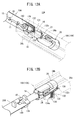
- FIG. 12A is a perspective view of the state in which the support spring portion is displaced to the second position as seen obliquely from below
- FIG. 12B is a view when the catheter hub, the auxiliary member hub, and the needle protection member are retracted in the proximal direction. It is the perspective view which looked at the state from the slanting upper side. It is a perspective view which shows the whole structure of the catheter assembly which concerns on 2nd Embodiment of this invention.
- FIG. 12A is a perspective view of the state in which the support spring portion is displaced to the second position as seen obliquely from below
- FIG. 12B is a view when the catheter hub, the auxiliary member hub, and the needle protection member are retracted in the proximal direction. It
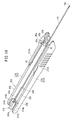
- FIG. 14 is a perspective view showing a needle hub and an inner needle of the catheter assembly of FIG. 13. It is a perspective view which shows the whole structure of the catheter assembly which concerns on a 2nd modification. It is a perspective view which shows the whole structure of the catheter assembly which concerns on a 3rd modification.
- the catheter assembly 10 is used for constructing an introduction portion for a medicinal solution or the like by being punctured and placed in the patient's body when performing transfusion or blood transfusion to a patient (living body).
- the catheter assembly 10 may be configured as a catheter that is longer than the peripheral venous catheter (eg, a central venous catheter, a PICC, a midline catheter, etc.).
- the catheter assembly 10 may be configured as a peripheral venous catheter.
- the catheter assembly 10 is not limited to a venous catheter, and may be configured as an arterial catheter such as a peripheral artery catheter.
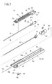
- the catheter assembly 10 includes a catheter 12, a catheter hub 14 that fixes and holds the catheter 12, and a hollow inner needle 16 that is inserted into the catheter 12.
- a needle hub 18 for fixing and holding the inner needle 16 a catheter operating member 20 mounted on the upper side of the catheter hub 14, a tubular auxiliary member 22 inserted between the catheter 12 and the inner needle 16, and an auxiliary member 22
- a needle protection member 26 connected to the proximal end of the catheter hub 14 and the auxiliary member hub 24.
- a user When used, a user such as a doctor or nurse grasps the needle hub 18 of the catheter assembly 10 in the initial state shown in FIG. 1 and punctures the distal end of the multiple tube portion 11 into a blood vessel (vein or artery) of the patient. . While maintaining this puncture state, the user advances the catheter operation member 20 relative to the needle hub 18 to advance the catheter 12 further to the distal end side (back part of the blood vessel) than the inner needle 16.
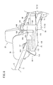
- the needle protection member 26 comes out of the tip of the needle hub 18, and the needle protection member 26 stores the needle tip 16a of the inner needle 16.
- the catheter 12 and the catheter hub 14 can be separated from the auxiliary member hub 24 and the needle protection member 26 that have come out of the needle hub 18, and are detached from the auxiliary member 22 as the advancement continues.
- the catheter operating member 20 is detached from the catheter hub 14, whereby the catheter 12 and the catheter hub 14 are placed in the patient.
- the catheter assembly 10 will be specifically described.
- the constituent material of the catheter 12 is not particularly limited, but a soft resin material is suitable, for example, polytetrafluoroethylene (PTFE), ethylene-tetrafluoroethylene copolymer (ETFE), perfluoroalkoxy fluororesin.
- PTFE polytetrafluoroethylene
- ETFE ethylene-tetrafluoroethylene copolymer
- Fluorine resins such as (PFA), olefin resins such as polyethylene and polypropylene, or a mixture thereof, polyurethane, polyester, polyamide, polyether nylon resin, a mixture of the olefin resin and an ethylene / vinyl acetate copolymer, etc. can give.
- a hollow portion 15 is provided that communicates with the lumen 13 of the catheter 12 and can distribute the infusion.
- the hollow portion 15 may contain a hemostasis valve, a plug, etc. (not shown) that prevent backflow of blood when the inner needle 16 is punctured and enable infusion with insertion of a connector of an infusion tube.
- annular protrusion 28 that protrudes radially outward and circulates in the circumferential direction of the catheter hub 14 is formed near the tip of the outer peripheral surface of the catheter hub 14. Further, similarly to the annular protrusion 28, a threaded portion 30 that circulates in the circumferential direction of the catheter hub 14 is formed at the proximal end of the outer peripheral surface of the catheter hub 14.
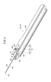
- the inner needle 16 of the catheter assembly 10 is configured as a hollow tube having rigidity capable of piercing the skin of a living body, and is disposed through the lumen 13 of the catheter 12 and the hollow portion 15 of the catheter hub 14.
- the inner needle 16 is formed to have a longer length than the catheter 12 and gradually increase in diameter from the proximal end portion toward the distal end, and a sharp needle tip 16a is provided at the distal end.
- the multiple tube portion 11 exposes the needle tip 16 a from the catheter 12 and the auxiliary member 22.
- a through hole 16 b is provided in the inner needle 16 along the axial direction of the inner needle 16.
- a groove (not shown) may be provided on the outer peripheral surface of the inner needle 16 along the axial direction.
- the inner needle 16 may be a solid needle.
- the needle hub 18 is configured as a housing 19 having a lower wall 32 and a pair of side walls 34 a and 34 b protruding upward from a side portion 32 a of the lower wall 32.
- the housing 19 has an elongated hook shape extending shorter than the axial length of the inner needle 16.
- an accommodation space 40 for accommodating a part of the multiple tube portion 11, the catheter hub 14, the auxiliary member hub 24 and the needle protection member 26 is formed.
- the resin material constituting the needle hub 18 is not particularly limited, and, for example, the materials listed for the catheter hub 14 can be selected as appropriate.
- the catheter assembly 10 exposes the catheter hub 14 and the needle protection member 26 on the upper side so that the relative rotation of the catheter 12 with respect to the inner needle 16 can be operated.
- the catheter assembly 10 may be configured to cover the catheter hub 14 and the needle protection member 26 by forming an upper wall in the housing 19 or attaching a lid.
- the lower wall 32 has a pair of side portions 32a formed in a flat shape and a guide groove portion 32b sandwiched between the pair of side portions 32a and recessed downward in an arc shape.
- the guide groove 32 b arranges the catheter hub 14, the auxiliary member hub 24 and the needle protection member 26 slidably along the longitudinal direction of the housing 19.
- a needle holding portion 36 that protrudes upward from the upper surface of the lower wall 32 and at the center in the width direction (guide groove portion 32b) and that fixes the proximal end portion of the inner needle 16 at a predetermined height is integrally formed.
- the needle holding portion 36 may be formed separately from the housing 19 and bonded and fixed to the housing 19.
- the pair of side walls 34a and 34b extend in parallel with the lower wall 32 in the longitudinal direction, and the vertical width on the base end side and the intermediate side is constant, and the vertical width on the distal end side is formed wider than the intermediate side.
- a groove-like rail portion 42 is provided on the upper end side of each side wall 34a, 34b.
- the pair of rail portions 42 linearly extend along the longitudinal direction on the inner surfaces of the wide portions of the side walls 34a and 34b, and reach the upper surface on the intermediate side.
- Each rail portion 42 accommodates the side edges 46 a and 46 b of the catheter operation member 20 and guides the advancement and retraction of the catheter operation member 20.
- the tip of the groove wall constituting the rail portion 42 is formed on a curved surface 42 a that allows the catheter operating member 20 to be curved.
- the wall between the concave portion 43 for use and the window 43c is formed with a recess in which the shaft rod portion 100 is disposed. Further, the lower wall 32 is formed with a locking recess 43d into which the locking protrusion 118 is inserted when the support main body 102 of the support member 44 is rotated by approximately 90 °.
- the auxiliary member 22 of the catheter assembly 10 has a function of supporting the catheter 12 from the inside and assisting the insertion of the catheter 12 into the blood vessel.
- the auxiliary member 22 is formed in a hollow tube having an outer diameter smaller than the inner diameter of the catheter 12 and an inner diameter larger than the outer diameter of the inner needle 16.
- the base end portion of the auxiliary member 22 is fixedly held on the auxiliary member hub 24 by an appropriate fixing method (caulking, fusing, bonding, etc.).
- the distal end side of the auxiliary member hub 24 is detachably assembled to the catheter hub 14, and the needle protection member 26 is detachably assembled to the proximal end side thereof.
- the auxiliary member hub 24 connects the catheter hub 14 and the needle protection member 26 so as to be integrally rotatable.
- the auxiliary member hub 24 may be integrated with the needle protection member 26 (that is, the auxiliary member 22 is fixed to the needle protection member 26).
- the catheter assembly 10 may not include the auxiliary member 22 and the auxiliary member hub 24. In this case, the needle protection member 26 is directly attached to the proximal end side of the catheter hub 14.
- the needle protection member 26 has the inner needle 16 penetratingly arranged in the initial state. Then, as the catheter 12 and the inner needle 16 are detached, the moved needle tip 16a is accommodated inside to prevent re-exposure of the needle tip 16a.
- the needle protection member 26 houses a shutter 82 and a retaining member 94 inside to prevent re-exposure of the needle tip 16a.
- the shutter 82 is elastically deformed by coming into contact with the outer peripheral surface of the inner needle 16 with the inner needle 16 penetratingly arranged.
- the shutter 82 is elastically restored when the needle tip 16a is removed, and the passage path of the inner needle 16 is blocked.
- the retaining member 94 has a hole having a diameter smaller than that of the needle tip 16a of the inner needle 16, thereby restricting the needle tip 16a from coming out in the proximal direction.
- the catheter operating member 20 holds the catheter 12 directly and is attached to the catheter hub 14, thereby moving the catheter 12 and the catheter hub 14 forward and backward relative to the inner needle 16 and the housing 19.
- the catheter operating member 20 is integrally formed with the operation plate portion 46 (long portion) extending in the longitudinal direction of the housing 19 and the base end of the operation plate portion 46, and is attached to and detached from the catheter hub 14. And a hub mounting portion 48 that is freely mounted.
- the operation panel unit 46 is a part where the user's finger is applied and the advance / retreat operation is performed.
- the pair of side edges 46 a and 46 b of the operation plate portion 46 are disposed on the pair of rail portions 42 and the upper surfaces of the pair of side walls 34 a and 34 b on the proximal end side of the rail portion 42 in the initial state.
- the operation plate portion 46 is formed to be sufficiently thin so that it can be bent in a direction perpendicular to the surface direction of the operation plate portion 46, that is, in a direction away from the inner needle 16.
- the material which comprises the operation board part 46 (catheter operation member 20) is not specifically limited, For example, the material raised with the catheter hub 14 can be selected suitably.
- the operation plate portion 46 is formed in a substantially rectangular shape in a plan view, but a notch portion 47 is provided on the base end side of the side edge 46a (on the side where the support member 44 is installed). It has been.
- the notch 47 forms a step 47 a at the boundary between the formation location and the operation plate 46 by cutting the operation plate 46 inward in the width direction.
- an inclined edge 46c that is gently inclined inward in the width direction toward the proximal direction is formed on the side edge 46a on the distal end side with respect to the step 47a.
- an upper rib 50 and tabs 52 and 54 are provided on the upper surface of the operation plate portion 46, and a tip warp portion 56 is provided at the tip of the operation plate portion 46.
- a holding portion 58 and a lower rib 51 are provided on the lower surface of the operation plate portion 46.
- a plurality of the upper ribs 50 and the lower ribs 51 are provided along the longitudinal direction of the operation plate portion 46. These upper and lower ribs 50, 51 protrude vertically and extend linearly along the width direction of the operation plate portion 46, thereby increasing the strength in the width direction of the operation plate portion 46. As a result, the operation plate portion 46 is prevented from being bent or bent in the housing 19 even when an external force is applied from the outside, and smoothly advances and retreats along the upper surfaces of the pair of side walls 34 a and 34 b and the rail portion 42.
- the tabs 52 and 54 are portions that are assumed to be directly touched by the user's finger, and protrude higher than the upper rib 50.
- the number of installed tabs 52 and 54 is not limited to two as shown in FIG. 2, and one or three or more may be provided.
- the tip warped portion 56 has a thick portion 56 a that protrudes on the lower surface side of the operation plate portion 46, and the tip warped portion 56 is thinned toward the tip from the thick portion 56 a and faces upward. Is curved.
- An insertion groove 57 through which the catheter 12 passes without contact or with a weak frictional force is formed at the center in the width direction of the thick portion 56a.
- a plurality (five in FIG. 6) of holding portions 58 of the catheter operation member 20 are provided along the longitudinal direction of the operation plate portion 46.
- the holding portions 58 are arranged at equal intervals in the longitudinal direction of the operation plate portion 46, and are held (held) in contact with the outer peripheral surface of the catheter 12 at each location.
- the catheter operation member 20 may be configured to hold the catheter 12 by providing a holding portion 58 at a predetermined position.
- the plurality of holding portions 58 have a pair of protruding pieces 70 (projecting portions) that protrude downward from the lower surface of the operation plate portion 46.
- the pair of projecting pieces 70 are formed symmetrically with respect to the intermediate portion in the width direction of the operation plate portion 46 (hereinafter, the projecting piece 70 on the near side in FIG. 6 is referred to as the first projecting piece 71 in FIG.
- the rear protrusion 70 is also referred to as a second protrusion 72).
- the first and second projecting pieces 71 and 72 are formed in a rectangular shape that is wide in the width direction of the operation plate portion 46.
- the inner edges of the first projecting piece 71 and the second projecting piece 72 are set to be slightly wider than the outer diameter of the catheter 12.
- claw portions 73 and 74 that protrude in a minute amount in the width direction are provided.
- the protruding ends of the pair of claws 73 and 74 are set to be slightly narrower than the outer diameter of the catheter 12 by being close to each other.
- the catheter 12 is easily held between the first and second projecting pieces 71 and 72 after passing through the pair of claws 73 and 74 when assembled to the catheter operating member 20.
- “getting in” means that the holding portion 58 holds the catheter 12 in contact with a weak engagement force.
- the configuration of the holding portion 58 is not limited to the pair of projecting pieces 70, and various configurations for holding the catheter 12 can be applied.
- the first and second projecting pieces 71 and 72 are formed in a quadrangular shape having rounded corners at the projecting end (lower end) in a side sectional view.
- the round corners of the first and second projecting pieces 71 and 72 allow the first and second projecting pieces 71 and 72 to easily get over the support member 44 on the lower side when the catheter operating member 20 advances and retreats ( Improve slidability).
- first and second projecting pieces 71 and 72 are formed so as to protrude from each other along the longitudinal direction of the operation plate portion 46. That is, the first projecting piece 71 and the second projecting piece 72 hold the catheter 12 with a weak engagement force by not pinching the catheter 12 on the same axis. For this reason, when the operation plate portion 46 is curved, the catheter operating member 20 is removed by shifting the catch of the catheter 12 in the order of the first projecting piece 71 and the second projecting piece 72.
- the hub mounting portion 48 of the catheter operation member 20 is box-shaped by a pair of side plates 60 protruding downward from the operation plate portion 46 and a semi-cylindrical upper plate 62 slightly protruding upward from the operation plate portion 46. Formed.
- the pair of side plates 60 has a base end side and an intermediate side extending in parallel, and a distal end side connected to the intermediate side is inclined inward toward the distal end direction.
- a mounting chamber 64 that accommodates the catheter hub 14 in a rotatable manner and restricts movement of the catheter hub 14 in the axial direction with respect to the hub mounting portion 48.
- the mounting chamber 64 is open to the outside at the lower portion and the base end of the hub mounting portion 48.
- a locking groove 66 having a trapezoidal hole and a circular hole, a pair of side plates 60 and an upper plate 62 extending in a U-shape, and a hub mounting portion 48 facing inward. And a pair of protrusions 69 projecting from each other.
- the locking groove 66 is arranged in a circular hole through the catheter 12 by a trapezoidal hole having a wide lower side and a narrow upper side, and is hooked on a boundary portion between the trapezoidal hole and the circular hole to appropriately lock the catheter 12.
- the groove portion 68 accommodates the annular protrusion 28 of the catheter hub 14 while being rotatable and restricting movement in the distal and proximal directions.
- the pair of protrusions 69 hook the proximal end side outer peripheral surface of the catheter hub 14 with a light engagement force.
- the catheter assembly 10 includes a support member 44 on the distal end side of the housing 19 in order to support the lower side of the catheter 12 held by the catheter operation member 20.
- the support member 44 includes a cylindrical shaft rod portion 100 and a support main body portion 102 that protrudes laterally from the shaft rod portion 100 (in a direction orthogonal to the axis of the shaft rod portion 100).
- the shaft rod portion 100 extends short in the vertical direction, and the upper end portion and the lower end portion thereof are respectively inserted into the pair of upper and lower support hole portions 43a and 43b of the arrangement recess 43. Is done.
- the support member 44 is rotatably assembled to the housing 19 with the shaft rod portion 100 as a base point.
- a connecting reinforcing portion 104 corresponding to the vertical width of the arrangement recess 43 is bulged and formed on the lower side of the shaft rod portion 100 in the assembled state of the housing 19 of the support member 44.
- the support main body 102 is connected to the connection reinforcing portion 104.
- a pair of cam convex portions 106 (cam portions) functioning as cam portions for rotating the support member 44 are integrally formed on the upper side of the shaft rod portion 100.
- the pair of cam projections 106 are provided at predetermined positions (positions accommodated in the window 43c in the assembled state of the housing 19), and protrude in the opposite direction and to the same extent with the shaft rod portion 100 interposed therebetween.
- the support member 44 has an operation member groove portion 108 at a position facing the support main body portion 102 of the shaft rod portion 100 and the pair of cam convex portions 106.
- the operating member groove 108 extends linearly from the most distal end of the cam convex portion 106 on the distal end side to the most proximal end of the cam convex portion 106 on the proximal end side.
- the operation member groove portion 108 is disposed at a position corresponding to the rail portion 42, and slidably accommodates the side edge 46 a of the catheter operation member 20 together with the rail portion 42.
- the support main body portion 102 of the support member 44 is a portion that moves by rotation with the shaft rod portion 100 as a base point in the assembled state of the housing 19.
- the support main body 102 is positioned in the accommodation space 40 and can contact and support the catheter 12 (see FIG. 7B and FIG. 10A), and unlike the first position P1, It is displaced to the second position P2 (see FIG. 10B) that is located in the placement recess 43 and is not in contact with the catheter 12.
- the angle between the first position P1 and the second position P2 with the shaft rod portion 100 as the axis center may be 90 ° or more so that the catheter hub 14, the auxiliary member hub 24 and the needle protection member 26 can be easily removed. preferable. In the present embodiment, the angle is set to 90 ° so that the cam convex portion 106 is positioned in the rail portion 42 at the second position P2.
- the support main body portion 102 is formed in an S shape having a size substantially equal to the vertical width of the placement concave portion 43 in a front view, and has a spring force that can be elastically deformed in the vertical direction.
- a raised portion 110 is provided that slightly rises upward.
- the raised portion 110 can contact the catheter 12 (multiple tube portion 11) held by the catheter operation member 20 at the first position P ⁇ b> 1 of the support main body portion 102.
- the support main body portion 102 is configured to be in contact with and supported by the user's pressing while facing the non-contact with the catheter 12 in the arrangement state of the first position P1, but is not limited thereto.
- positioning of 1 position P1 may be sufficient.
- a distal end inclined surface 112 that is inclined in the distal direction and downward is formed on the upper distal end side of the support main body 102, and a proximal end that is inclined in the proximal direction and downward is formed on the upper proximal end side of the support main body 102.
- An inclined surface 114 is formed.
- a wing 116 that protrudes in an inclined manner toward the outer side and the lower side in the width direction away from the shaft rod portion 100 is integrally formed at an end portion of the support main body portion 102 that is continuous with the raised portion 110.
- a locking projection 118 is formed on the lower surface of the support main body 102 so as to protrude downward.
- the locking projection 118 is inserted into the locking recess 43 d of the housing 19 at the second position P ⁇ b> 2 of the support main body 102.
- a contact protrusion 120 that protrudes in the proximal direction is provided at the lower end of the support main body 102.
- the contact protrusion 120 contacts the side plate 60 (hub mounting portion 48) when the catheter operating member 20 advances, and induces displacement of the support main body portion 102 to the second position P2 that is 90 ° away from the first position P1. To do.
- the material constituting the support member 44 is not particularly limited, and, for example, the material raised in the catheter hub 14 can be selected as appropriate.
- the support member 44 is not only provided separately from the housing 19 but may be integrally formed with the housing 19. Further, the support member 44 is not provided only on the side wall 34a of the housing 19, but may be provided on the side wall 34b, or a pair may be provided on both the side walls 34a and 34b. Further, the rotation direction of the support main body 102 is not limited to the planar direction of the housing 19 but may be a side surface direction including upper and lower sides.
- the catheter assembly 10 according to the present embodiment is basically configured as described above, and the effects thereof will be described below.
- the catheter assembly 10 is used when constructing an infusion part for an infusion to a patient.
- the catheter hub 14, the auxiliary member hub 24, and the needle protection member 26 are connected, and the catheter hub 14 is accommodated in the mounting chamber 64 of the catheter operation member 20 (hub mounting portion 48). It is integrally accommodated in the accommodating space 40 of the housing 19.
- the support main body portion 102 of the support member 44 assembled to the distal end portion of the housing 19 stands by at the first position P1, and is held by the plurality of holding portions 58 of the catheter operation member 20 as shown in FIG. It faces the multiple tube section 11 formed.
- Each holding portion 58 grips the outer peripheral surface of the catheter 12 with a weak engagement force at each position in the axial direction, and firmly holds the catheter 12 as the entire catheter operation member 20.
- the user grasps the housing 19 to puncture the patient with the multiple tube portion 11.
- the holding portion 58 holds the catheter 12, so that the multiple tube portion 11 is prevented from being bent in the housing 19 even if a resistance force accompanying puncturing is received.
- the multiple tube portion 11 is contacted and supported by the support member 44 waiting at the first position P1. For this reason, the multiple tube part 11 is fixed between the catheter operating member 20 (the insertion groove 57 of the distal end warp part 56) and the support member 44 (the raised part 110), and the bending is further suppressed.
- the catheter assembly 10 can be formed to be thinner by reducing the strength of the inner needle 16, thereby reducing the burden on the patient.
- the user advances the catheter 12 relative to the inner needle 16 and inserts it into the blood vessel.
- the user applies a finger to the upper rib 50 and the tabs 52 and 54 of the catheter operating member 20 to advance (relatively move) the catheter operating member 20 in the distal direction with respect to the housing 19.
- the holding of the multi-tube portion 11 by the holding portion 58 is continued, and the catheter 12 advances smoothly.
- the side edge 46 a of the operation plate portion 46 exists in the operation member groove portion 108 of the support member 44, so that the support member 44 cannot rotate and the support main body portion 102.
- the support member 44 continues to be in a state in which the lower side of the multiple tube portion 11 can be supported, and even if the catheter 12 receives a reaction force from the skin or the like when the catheter 12 is inserted, the multiple tube portion from the holding portion 58 11 is suppressed. Therefore, for example, the needle tip 16a of the inner needle 16 is not retracted due to bending and does not come out of the skin, and inconveniences such as re-piercing the inner needle 16 into the skin are avoided.
- the support main body 102 has an elastic force in the vertical direction and has the base end inclined surface 114, so that when the holding portion 58 (the pair of projecting pieces 70) comes into contact when the support main body 102 is advanced, the supporting main body portion 102 is appropriately elastically deformed. 58 is allowed to pass. Thereby, the catheter operation member 20 advances the catheter 12 smoothly.
- the operation plate portion 46 of the catheter operation member 20 has the axis of the multiple tube portion 11 when the distal warp portion 56 comes into contact with the patient's skin or the like with advancement in the distal direction or when the user grips the distal warp portion 56. Curves away from the direction.
- the bending of the operation plate portion 46 occurs from the distal end side of the operation plate portion 46, and each holding portion 58 arranged in the longitudinal direction sequentially removes the multiple tube portion 11 from the distal end side against individual engagement forces. Even if the holding portion 58 on the distal end side releases the holding due to the bending of the operation plate portion 46, the holding portion 58 on the proximal end side that maintains the linearity in the housing 19 continues to hold the multiple tube portion 11. Can do. Further, the support main body portion 102 of the support member 44 continues to stand by at the first position P1 and continues to support the multiple tube portion 11 together with the holding portion 58 that holds the catheter 12 on the proximal end side.
- the user may temporarily retract the catheter operation member 20 to retract the catheter 12 relative to the inner needle 16 and the housing 19.
- the operation plate portion 46 is re-accommodated in the rail portion 42 of the housing 19 and shifts from a curved state to a linear shape (non-curved state).
- the wing 116 and the raised portion 110 lift the catheter 12 toward the holding portion 58 and cause it to be held in the holding portions 58 (the pair of projecting pieces 70) again. Can do.
- the inclined edge 46c of the operation plate portion 46 shown in FIG. 9B is located in the operation member groove portion 108 from the state where the side edge 46a shown in FIG. 9A is located in the operation member groove portion 108. Transition to the state.
- the side plate 60 of the hub mounting portion 48 contacts the contact protrusion 120 of the support main body portion 102, so that the support main body portion 102 starts to rotate from the first position P1.
- the cam convex portion 106 When the step 47a of the operation plate portion 46 passes through the cam convex portion 106 on the distal end side of the support member 44, the cam convex portion 106 is positioned at the notch portion 47, and the support member 44 becomes rotatable.
- the contact protrusion 120 of the support main body 102 rotates the support main body 102 at a sufficient rotation angle (90 °) by the contact of the catheter operation member 20.
- the support main body portion 102 is displaced from the first position P1 shown in FIG. 10A to the second position P2 shown in FIG. 10B to greatly open the front end side of the accommodation space 40.
- the catheter hub 14, the auxiliary member hub 24, and the needle protection member 26 can pass in the distal direction, and can be easily removed from the housing 19.
- the support protrusions 118 are inserted into the lock recesses 43d, thereby causing the support main body 102 to wait at the second position P2.
- one of the cam convex portions 106 is located in the rail portion 42. Therefore, when the user performs the backward operation of the catheter operation member 20, the support member 44 is rotated by the contact between the step 47a and the cam convex portion 106, and the support main body portion 102 is returned from the second position P2 to the first position P1 again. it can.
- the wing 116 extends obliquely downward, so that the catheter 12 is guided to the upper part of the support main body 102 while avoiding the lateral displacement of the catheter 12. Therefore, the support member 44 can hold the catheter 12 into the holding portion 58 again as the catheter operation member 20 is retracted.
- the catheter hub 14 attached to the hub attachment portion 48 and the needle protection member 26 attached to the catheter hub 14 also advance.
- the needle tip 16 a of the inner needle 16 is accommodated in the needle protection member 26.
- the needle protection member 26 regulates the withdrawal of the needle tip 16a by the retaining member 94, and the shutter 82 that has been contracted by the outer peripheral surface of the inner needle 16 in the needle protection member 26 develops in front of the needle tip 16a. This prevents re-exposure of the needle tip 16a.
- the locking of the locking groove 66 and the pair of protrusions 69 of the hub mounting portion 48 with the catheter hub 14 can be easily released. Therefore, the user separates the catheter operation member 20 from the catheter 12 and the catheter hub 14 at an appropriate timing, so that the catheter 12 and the catheter hub 14 are well placed in the patient.
- the catheter assembly 10 can support the catheter 12 on the opposite side of the catheter operation member 20 by the support member 44 located at the first position P1. Therefore, even when the catheter 12 receives a reaction force from the patient during the advancement operation of the catheter operation member 20, the support member 44 can support and support the catheter 12 in the housing 19 and suppress its deflection. Thereby, the extended state of the multiple tube part 11 is maintained well, and the user can insert the catheter 12 into the patient well. Further, the support member 44 can be advanced from the first position P1 to the second position P2 without interfering with the catheter hub 14 and the catheter operation member 20, and can be easily detached from the inner needle 16 and the housing 19. it can.
- the catheter assembly 10 is supported by the catheter 12 being sandwiched between the catheter operating member 20 and the support member 44, thereby suppressing the bending of the multiple tube portion 11 even when the multiple tube portion 11 is punctured into a patient. It becomes possible to do. Therefore, the user can puncture the multiple tube portion 11 without a sense of incongruity.
- the support main body part 102 can support the catheter 12 stably because the movement from the first position P1 is restricted in the initial state.
- the catheter hub 14 and the catheter operation member 20 can be smoothly exposed from the housing 19.
- the holding part 58 holds the catheter 12 directly, it is possible to suppress the bending by the catheter operating member 20 when the multiple tube part 11 is punctured or when the catheter 12 is inserted. At this time, since the support member 44 can support the catheter 12 on the opposite side of the catheter operation member 20, the removal of the catheter 12 from the holding portion 58 can be suppressed.
- the support main body 102 when the support member 44 is rotatably mounted on the housing 19, the support main body 102 can be displaced at a short distance between the first position P ⁇ b> 1 and the second position P ⁇ b> 2. Can be achieved. And the support main-body part 102 is smoothly displaced between the 1st position P1 and the 2nd position P2 by being rotatably provided in the housing 19 by the shaft bar part 100. FIG. Thereby, the supportable state of the catheter 12 and the detachable state of the catheter hub 14 and the like can be easily switched.
- the support member 44 becomes non-rotatable and the support main body portion 102 is kept waiting at the first position P1 where the catheter 12 can be supported. be able to.
- the support member 44 is rotatable, and the support body is in the second position P2 allowing passage of the catheter hub 14 and the like. The part 102 can be displaced.
- the support main body 102 can allow passage of the holding portion 58 by elastically deforming even when the holding portion 58 holding the catheter 12 comes into contact with the catheter operating member 20 when the catheter operating member 20 is advanced or retracted. Therefore, sufficient mobility of the catheter operation member 20 can be ensured.
- the catheter operating member 20 can reliably arrange the support main body 102 from the first position P1 to the second position P2 by largely rotating the support main body 102 by contacting the contact protrusion 120 at the time of advancement. Therefore, when the catheter operating member 20 is retracted, unintentional contact between the catheter operating member 20 and the support member 44 can be avoided and the catheter operating member 20 can be smoothly retracted.
- the catheter assembly 10 is not limited to the above-described embodiment, and various application examples and modification examples can be taken.
- the catheter assembly 10 accommodates a guide wire (not shown) in the through-hole 16b of the inner needle 16, and operates a guide wire operating member (not shown) connected to the guide wire, so that the guide wire is guided from the needle tip 16a.
- the structure which guides the catheter 12 by exposing may be sufficient.
- the support member 44 that can support the catheter 12 in the housing 19 is not limited to the above-described configuration.
- a slider that slides between the first position P1 and the second position P2 instead of the support member 44 may be applied.
- the slider may be configured to advance and retract in the width direction of the housing 19 (direction orthogonal to the moving direction of the catheter 12).
- the slider can be easily switched between the first position P1 where the catheter 12 can be supported near the axis of the housing 19 and the second position P2 where the passage of the catheter hub 14 and the like is allowed outside the housing 19. it can.
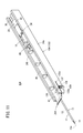
- the catheter assembly 10A according to the first modification differs from the catheter assembly 10 in that a torsion spring 130 is employed as a support member for supporting the catheter 12, as shown in FIG. Further, the needle hub 18A (housing 19A) of the catheter assembly 10A includes a housing portion 132 for placing the torsion spring 130 in place of the placement recess 43 described above.
- the housing portion 132 slightly bulges outward in the width direction from the side wall 34a of the housing 19A, and has a spring housing chamber (not shown) therein. Further, the accommodating portion 132 includes a slit 132a on the lower side of the rail portion 42 through which the supporting spring portion 136 can be passed when the supporting spring portion 136 of the torsion spring 130 described later is displaced.
- the torsion spring 130 includes a coil part 134 in which a wire made of a metal material is spirally wound, and a support spring part 136 (support) that protrudes laterally from the upper end of the coil part 134 (a direction orthogonal to the axis of the coil part 134).
- the coil part 134 is assembled to the housing 19A so that its axial direction is along the vertical direction of the housing 19A.
- the coil part 134 has the pin 134a which protrudes from a lower end part, and this pin 134a is fixed to the accommodating part 132 so that rotation is impossible.
- the support spring portion 136 is formed in a U shape in plan view, and from the coil portion 134 to a position beyond the multiple tube portion 11 and the holding portion 58 (first position P1) in a state where the torsion spring 130 is assembled to the housing 19A. Extend. Thereby, the support spring part 136 can support the multiple tube part 11 when the user operates the catheter operation member 20A, and suppresses the bending of the multiple tube part 11. Since the support spring part 136 is elastically deformed up and down by the spring force of the coil part 134 and the support spring part 136 itself, when the catheter operation member 20A is advanced and retracted, it escapes downward with the contact of the holding part 58, and the holding part 58 To pass easily.
- the hub mounting portion 48 of the catheter operation member 20A is constituted by a pair of legs 138 that sandwich the outer peripheral surface of the catheter hub 14. Furthermore, the catheter operation member 20A includes a block 140 projecting downward on the lower surface near the side edge 46a on the front side of the pair of leg portions 138. As the catheter operating member 20A advances, the block 140 comes into contact with the support spring portion 136 and rotates (elastically deforms) the support spring portion 136 counterclockwise in plan view. Accordingly, the support spring portion 136 is displaced to the position (second position P2) inserted into the slit 132a on the distal end side and allows passage of the catheter hub 14, the auxiliary member hub 24, and the needle protection member 26.
- the needle protection member 26 and the like come into contact with the support spring portion 136, and the support spring portion 136 is moved. Rotate in the proximal direction. Accordingly, the support spring portion 136 is inserted into the slit 132a on the proximal end side, and allows the catheter hub 14, the auxiliary member hub 24, and the needle protection member 26 to pass therethrough.
- the torsion spring 130 can stably support the multiple tube portion 11 until it is pressed by the block 140, and effectively suppresses the bending of the multiple tube portion 11.
- the torsion spring 130 can easily pass through the catheter hub 14, the auxiliary member hub 24, and the needle protection member 26 as the block 140 is pressed.
- the torsion spring 130 may be provided with the wing 116 and the contact protrusion 120 described above.
- the catheter assembly 200 is different from the needle hub 18 of the catheter assembly 10 according to the first embodiment in the shape of the needle hub 202.
- the needle hub 202 includes a housing 204 and a pair of arms 212 protruding from the housing 204 in the distal direction.
- the housing 204 includes a lower wall 206 having a pair of side portions 32a and a guide groove portion 32b, and a pair of side walls 208 protruding upward from both side portions of the lower wall 206.
- the lower wall 206 and the pair of side walls 208 are included.
- a housing space 204a is formed inside the housing.
- the needle protection member 26 is housed in the housing space 204a of the housing 204 in the initial state.
- the catheter assembly 200 does not include the auxiliary member 22 and the auxiliary member hub 24 described above, but it goes without saying that these configurations may be included.
- a needle holding member 210 formed as a separate component from the housing 204 is fixed to the lower wall 206 of the housing 204 on the proximal end side from the needle protection member 26.
- the needle holding member 210 includes a holding base 210a at the center in the width direction, a horizontal plate 210b that protrudes outward in the width direction from near the lower side of the holding base 210a and contacts the pair of side portions 32a, and a protruding end of the horizontal plate 210b. And a vertical plate 210c that protrudes upward from and contacts the pair of side walls 208.
- the holding base portion 210a holds the base end portion of the inner needle 16 at its upper portion.
- a hook-like connecting portion (not shown) is provided at the lower portion of the holding base portion 210a so as to be hooked in the mounting hole 206a (see FIG. 13) of the lower wall 206 and firmly fix the needle holding member 210 to the housing 204.
- the pair of arms 212 (the first arm 214 and the second arm 216) are connected to the pair of side walls 208 of the housing 204 and extend as they are toward the distal end.
- a rail portion 42 is provided on the inner surface of each of the pair of arms 212, and a grip 212a for a user to hold is provided on each outer surface.
- the first arm 214 is provided with a placement recess 43, a pair of support hole portions 43a and 43b, a window 43c, and a locking recess 43d, and the support member 44 is rotatably attached.
- the pair of arms 212 may be made of a metal material in order to increase its rigidity (that is, reinforce the extending posture), or a reinforcing member (not shown) such as a metal rod inside the resin material. May be embedded.
- the catheter assembly 200 according to the second embodiment is basically configured as described above, and can obtain the same effects as the catheter assembly 10. That is, by supporting the multiple tube portion 11 by the support member 44 attached to the needle hub 202, it is possible to satisfactorily suppress bending of the multiple tube portion 11 during puncturing.
- the needle hub 202 has a pair of arms 212, thereby reducing the weight of the entire assembly and reducing the friction when the catheter operating member 20 moves back and forth, thereby improving the mobility of the catheter operating member 20. Can be made.
- the catheter assembly 220 (needle hub 222) according to the second modification shown in FIG. 15 has a pair of arms 212 in the same manner as the needle hub 202 according to the second embodiment. It is the structure provided with the connection bridge
- the connecting bridge portion 224 is integrally formed with the pair of arms 212 at the inner surface on the tip side of the pair of arms 212 and at a lower position.
- the connecting bridge portion 224 has a length that matches the width direction of the lower wall 206 of the housing 204, and has a pair of side portions 32a and a guide groove portion 32b. Further, the axial length of the connecting bridge portion 224 corresponds to the installation range of the support member 44 and is set so as not to expose the support member 44 downward.
- the needle hub 222 includes the connecting bridge portion 224 on the distal end side of the pair of arms 212, whereby the distal end side of the pair of arms 212 and the entire interval can be made constant. Therefore, even if the user grips the vicinity of the grip 212a of the pair of arms 212, the shape of the needle hub 222 is maintained well, and the catheter operation member 20 can be smoothly advanced and retracted.
- the catheter assembly 230 (needle hub 232) according to the third modification shown in FIG. 16 includes a connecting rod 324 that connects the distal ends of the pair of arms 212 instead of the connecting bridge portion 224 described above. It has become.
- the connecting rod 324 is a member made of, for example, a metal material and formed into a round bar. The connecting rod 324 bridges the pair of arms 212 with a length that matches the width direction of the lower wall 206 in the same manner as the connecting bridge portion 224, thereby making the interval between the pair of arms 212 constant.
- the needle hubs 222 and 232 can employ various configurations that reinforce the extending posture of the pair of arms 212 and facilitate the movement of the catheter operation member 20.
- the connection bridging portion 224 and the connection rod 324 may be provided not only at the distal end side of the pair of arms 212 but also at an intermediate position in the extending direction of the pair of arms 212.
Abstract
カテーテル組立体(10)は、中空のカテーテル(12)、カテーテル(12)を固定保持するカテーテルハブ(14)、カテーテル(12)内に挿通される内針(16)、内針(16)を固定保持する針ハブ(18)、及びカテーテル(12)の移動を操作可能なカテーテル操作部材(20)を備える。また、針ハブ(18)には支持部材(44)が設けられ、この支持部材(44)は、カテーテル(12)を接触支持可能な第1位置(P1)と、第1位置(P1)と異なる位置でカテーテル(12)に非接触となる第2位置(P2)とに移動自在な支持本体部(102)を有する。
Description
本発明は、例えば患者に対して輸液等を行う際に、血管に穿刺し留置するカテーテル組立体に関する。
従来、患者に対して輸液等を行う際には、カテーテル組立体が使用される。この種のカテーテル組立体は、中空のカテーテルと、カテーテルの基端に固定されたカテーテルハブと、カテーテル内に挿入され先端に鋭利な針先を有する中空の内針と、この内針の基端に固定された針ハブとを備える(特表2013-529111号公報参照)。
また、特表2013-529111号公報に開示のカテーテル組立体は、患者の体内の奥深くにカテーテルを挿入するため、長尺なカテーテル及び内針を重ねた状態で、筒状の針ハブ内の軸方向に沿って収容している。医師や看護師等のユーザは、カテーテル及び内針を患者に穿刺し、この穿刺状態でカテーテルハブに接続されたカテーテル操作部材を進出操作することにより、内針及び針ハブに対し長尺なカテーテルを相対的に進出させて体内に挿入していく。
ところで、この種のカテーテル組立体は、体内へのカテーテルの挿入時に、針ハブの先端側を上下に分離させて、カテーテルの挿入後に、カテーテル、カテーテルハブ及びカテーテル操作部材を内針及び針ハブから離脱させる構成となっている。しかしながら、このように針ハブが分離する構成では、カテーテルの挿入時に、カテーテル及び内針が針ハブに対して非支持(自由)状態で延在することになり、カテーテルは患者から反力を受けると比較的容易に撓んでしまう。場合によっては、患者の挿入部から針先が後退して(抜けて)、この針先が患者に再び穿刺するおそれもある。
本発明は、上記の実情に鑑みてなされたものであり、カテーテルの挿入時にカテーテルを支持可能とすることでその撓みを抑制し、しかもカテーテルハブ及びカテーテル操作部材を針ハブから容易に離脱させ得るカテーテル組立体を提供することを目的とする。
前記の目的を達成するために、本発明に係るカテーテル組立体は、中空のカテーテルと、前記カテーテルを固定保持するカテーテルハブと、針先を有し、前記カテーテルの内部に離脱可能に挿通される内針と、前記内針を固定保持する針ハブと、前記内針に対する前記カテーテルの相対移動を操作可能なカテーテル操作部材と、前記針ハブに設けられる支持部材と、を備え、前記支持部材は、前記カテーテルを挟んだ前記カテーテル操作部材の反対側に配置されて前記カテーテルを接触支持可能な第1位置と、前記第1位置と異なる位置で前記カテーテルに非接触となる第2位置とに移動自在な支持本体部を有することを特徴とする。
上記によれば、カテーテル組立体は、第1位置に位置する支持部材により、カテーテル操作部材の反対側でカテーテルを支持することができる。そのため、カテーテル操作部材の進出操作時に、カテーテルが患者から反力を受けても、支持部材は、針ハブ内でカテーテルを接触支持してカテーテルの撓みを抑制することができる。これにより、カテーテル及び内針の延在状態が維持されて、ユーザは、カテーテルを患者に良好に挿入していくことが可能となる。また、支持部材は、第1位置から第2位置への変位により、カテーテルハブ及びカテーテル操作部材を邪魔することなく進出させ、針ハブから容易に離脱させることができる。
この場合、前記針先が前記カテーテルの先端から突出した初期状態で、前記カテーテルは前記カテーテル操作部材と前記支持部材に挟まれることにより支持されているとよい。
このように、カテーテルが初期状態でカテーテル操作部材と支持部材に挟まれて支持されることで、カテーテル及び内針を患者に穿刺した際もカテーテル及び内針の撓みを抑制することが可能となる。よって、ユーザは、カテーテル及び内針を違和感なく穿刺することができる。
また、前記支持部材は、初期状態で、前記支持本体部の前記第1位置からの移動が規制されており、前記カテーテル操作部材が前記針ハブに対して進出することに伴い、前記支持本体部の前記第1位置からの移動規制が解除される構成であるとよい。
このように、初期状態で第1位置からの移動が規制されていることで、カテーテルを安定的に支持することができる。その一方で、カテーテル操作部材の進出時に支持本体部の移動規制が解除されることで、カテーテルハブ及びカテーテル操作部材は、針ハブからスムーズに露出することができる。
さらに、前記カテーテル操作部材は、前記カテーテルを離脱可能に直接保持する保持部を有することが好ましい。
これにより、保持部は、カテーテルを直接保持するので、カテーテル及び内針の穿刺時やカテーテルの挿入時に、カテーテル操作部材により撓みを抑えることができる。この際、支持部材は、カテーテル操作部材の反対側でカテーテルを支持可能であるため、保持部からのカテーテルの抜けを抑制することができる。
そして、前記支持部材は、前記針ハブに回転自在に装着されているとよい。
このように、支持部材が針ハブに回転自在に装着されていると、支持本体部は、第1位置と第2位置を短い距離で変位することができ、カテーテル組立体の小型化を図ることができる。
また、前記支持部材は、前記針ハブに回転自在に装着される軸棒部を有し、前記支持本体部は、前記軸棒部の軸方向と直交する方向に突出しているとよい。
これにより、支持本体部は、針ハブに装着された軸棒部を回転中心に回転して第1位置と第2位置の間を円滑に変位し、カテーテルの支持可能状態と、カテーテルハブ等の離脱可能状態を容易に切り換えることができる。
上記構成に加えて、前記針ハブは、溝状のレール部を有し、前記軸棒部は、前記レール部に配置される溝部を有し、前記カテーテル操作部材は、前記レール部及び前記溝部に摺動自在に収容され、相対移動時に案内される側縁と、前記カテーテルハブとの装着位置に一致又は近接する位置で、前記側縁を切り欠くことにより形成され、前記レール部及び前記溝部に対し非収容となる切り欠き部と、を有することが好ましい。
これにより、カテーテル操作部材の側縁が溝部に存在する場合には、支持部材が回転不能となり、第1位置に支持本体部を待機させて、カテーテルの支持可能な状態を継続することができる。その一方で、カテーテル操作部材の切り欠き部が溝部に位置する場合には、支持部材が回転可能となり、支持本体部を第2位置に変位させて、カテーテルハブ及びカテーテル操作部材の通過を許容することができる。
また、前記軸棒部には、カム部が設けられ、前記溝部は、前記カム部の一方の端から前記カム部の他方の端まで延在しているとよい。
このように、カム部の両端にわたって溝部が設けられることで、カテーテル操作部材の側縁による支持部材の回転不能状態を、一層確実に維持することができる。また、カム部は、支持本体部が第2位置に位置する状態でレール部に入り込むことで、カテーテル操作部材の後退時にカテーテル操作部材の側縁が接触して、支持本体部を第2位置から第1位置へ変位させることができる。これにより、支持本体部によりカテーテルを再び支持することが可能となる。
さらに、前記支持本体部は、前記カテーテル操作部材の進出に伴い該カテーテル操作部材の基端部に接触して、前記支持本体部を前記第1位置から前記第2位置まで変位させる突起を有することが好ましい。
これにより、カテーテル操作部材は、進出時に突起に接触することにより支持本体部を大きく回転させて、第1位置から第2位置に支持本体部を確実に配置することができる。従って、カテーテル操作部材の後退操作時に、カテーテル操作部材と支持部材の意図しない接触を回避して、カテーテル操作部材をスムーズに後退させることが可能となる。
ここで、前記支持部材は、線材を巻回したコイル部と、前記支持本体部として構成されて前記コイル部から径方向外側に突出する突出部とを有するトーションバネであってもよい。
このように、支持部材がトーションバネにより構成されることで、突出部は、カテーテル操作部材の反対側でカテーテルを良好に支持可能となる。その一方で、突出部は、カテーテル操作部材の接触に伴うコイル部の弾性変形により、カテーテルハブ及びカテーテル操作部材の通過を容易に許容することができる。
また、前記支持本体部は、前記カテーテルの移動方向と直交する方向に弾性変形することが好ましい。
このように、支持本体部がカテーテルの移動方向と直交する方向に弾性変形することで、支持本体部は、カテーテル操作部材の進退操作時に、例えば保持部が接触しても積極的に撓むことにより、保持部の通過を許容することができる。従って、カテーテル操作部材の移動性を充分に確保することができる。
さらに、前記支持本体部は、第1位置に配置された状態で、前記カテーテルを接触支持可能な部分から前記針ハブの幅方向外側且つ下側に向かって傾斜しているとよい。
このように、支持本体部が針ハブの幅方向外側且つ下側に向かって傾斜していることで、カテーテル操作部材の後退時に、カテーテル操作部材から外れたカテーテルを傾斜した上面で受けることができるので、カテーテルが幅方向にずれることを抑止することができる。さらに、傾斜した上面は、支持部材の上部にカテーテルを案内して、カテーテル操作部材に再び保持させることができる。
本発明によれば、カテーテル組立体は、カテーテルの挿入時にカテーテルを支持可能とすることでその撓みを抑制し、しかもカテーテルハブ及びカテーテル操作部材を針ハブから容易に離脱させることができる。
以下、本発明に係るカテーテル組立体について好適な実施形態(第1及び第2実施形態)をあげ、添付の図面を参照して詳細に説明する。
本発明に係るカテーテル組立体10は、患者(生体)に輸液や輸血等を行う場合に、患者の体内に穿刺及び留置されて薬液等の導入部を構築するために使用される。カテーテル組立体10は、末梢静脈カテーテルよりも長さが長いカテーテル(例えば、中心静脈カテーテル、PICC、ミッドラインカテーテル等)として構成され得る。なお、カテーテル組立体10は、末梢静脈カテーテルとして構成されてもよい。また、カテーテル組立体10は、静脈用カテーテルに限らず、末梢動脈カテーテル等の動脈用カテーテルとして構成されてもよい。
〔第1実施形態〕
第1実施形態に係るカテーテル組立体10は、図1及び図2に示すように、カテーテル12と、カテーテル12を固定保持するカテーテルハブ14と、カテーテル12内に挿入される中空の内針16と、内針16を固定保持する針ハブ18と、カテーテルハブ14の上側に装着されるカテーテル操作部材20と、カテーテル12と内針16の間に挿入される管状の補助部材22と、補助部材22を固定保持する補助部材ハブ24と、カテーテルハブ14及び補助部材ハブ24の基端に接続される針保護部材26とを備える。
第1実施形態に係るカテーテル組立体10は、図1及び図2に示すように、カテーテル12と、カテーテル12を固定保持するカテーテルハブ14と、カテーテル12内に挿入される中空の内針16と、内針16を固定保持する針ハブ18と、カテーテルハブ14の上側に装着されるカテーテル操作部材20と、カテーテル12と内針16の間に挿入される管状の補助部材22と、補助部材22を固定保持する補助部材ハブ24と、カテーテルハブ14及び補助部材ハブ24の基端に接続される針保護部材26とを備える。
カテーテル組立体10は、使用前の初期状態で、カテーテル12、補助部材22及び内針16を外側から順に重ねた多重管構造(多重管部11)を形成している。カテーテル操作部材20は、この多重管部11を直接保持する構成となっている。さらに、カテーテル組立体10は、初期状態で、多重管部11の一部、カテーテルハブ14、カテーテル操作部材20、補助部材ハブ24及び針保護部材26を適宜組み付けて、針ハブ18内に収容している。
医師や看護師等のユーザは、使用時に、図1に示す初期状態のカテーテル組立体10の針ハブ18を把持し、多重管部11の先端を患者の血管(静脈又は動脈)内に穿刺する。この穿刺状態を維持したまま、ユーザは、カテーテル操作部材20を針ハブ18に対し相対的に進出操作することで、カテーテル12を内針16よりも先端側(血管の奥部)に進出させる。
カテーテル組立体10は、図3Aに示すように、カテーテル12の進出又はカテーテル12に対する針ハブ18の相対的な後退に伴い、カテーテル操作部材20に接続されたカテーテルハブ14、補助部材ハブ24及び針保護部材26も一体的に移動する。この際、内針16が針ハブ18に固定されていることで、多重管部11は、カテーテル12と補助部材22の2重構造に移行する。また、カテーテル操作部材20は、カテーテル12の進出操作時に、多重管部11の保持を解除する。
さらに進出を続けると、図3Bに示すように、針保護部材26まで針ハブ18の先端から抜け出て、この針保護部材26に内針16の針先16aが収容される。さらに、カテーテル12及びカテーテルハブ14は、図4Aに示すように、針ハブ18から抜け出した補助部材ハブ24及び針保護部材26と分離可能になり、進出の継続に伴い補助部材22から離脱する。最終的には、図4Bに示すように、カテーテル操作部材20がカテーテルハブ14から離脱することにより、カテーテル12及びカテーテルハブ14が患者に留置される。以下、このカテーテル組立体10について、具体的に説明していく。
図2に示すように、カテーテル組立体10のカテーテル12は、可撓性を有し、内部に内腔13が貫通形成されている。内腔13は、内針16及び補助部材22を収容可能且つ薬液や血液等を流動可能な直径に形成される。カテーテル12の長さは、特に限定されず用途や諸条件等に応じて適宜設計可能であり、例えば、14~500mm程度に設定され、あるいは30~400mm程度に設定され、あるいは76~200mm程度に設定される。
カテーテル12の構成材料は、特に限定されるものではないが、軟質樹脂材料が好適であり、例えば、ポリテトラフルオロエチレン(PTFE)、エチレン・テトラフルオロエチレン共重合体(ETFE)、ペルフルオロアルコキシフッ素樹脂(PFA)等のフッ素系樹脂、ポリエチレン、ポリプロピレン等のオレフィン系樹脂又はこれらの混合物、ポリウレタン、ポリエステル、ポリアミド、ポリエーテルナイロン樹脂、前記オレフィン系樹脂とエチレン・酢酸ビニル共重合体との混合物等があげられる。
カテーテル12の基端部は、適宜の固着方法(かしめ、融着、接着等)によってカテーテルハブ14内の先端部に固着される。カテーテルハブ14は、カテーテル12が血管内に挿入された状態で患者の皮膚上に露出され、テープ等により貼り付けられてカテーテル12とともに留置される。
カテーテルハブ14は、先端方向に先細りの筒状に形成される。カテーテルハブ14の構成材料は、特に限定されるものではないが、例えば、ポリプロピレン、ポリカーボネート、ポリアミド、ポリスルホン、ポリアリレート、メタクリレート-ブチレン-スチレン共重合体等の熱可塑性樹脂を適用するとよい。カテーテルハブ14の基端側には、内針16の離脱後に、図示しない輸液チューブのコネクタが接続される。
カテーテルハブ14の内部には、カテーテル12の内腔13に連通して輸液剤を流通可能な中空部15が設けられている。この中空部15には、内針16の穿刺時に血液の逆流を防ぐとともに、輸液チューブのコネクタの挿入に伴い輸液を可能とする、図示しない止血弁やプラグ等が収容されてもよい。
また、カテーテルハブ14の外周面の先端寄りには、径方向外側に突出し、カテーテルハブ14の周方向に周回する環状突起28が形成されている。さらに、カテーテルハブ14の外周面の基端には、環状突起28と同じく、カテーテルハブ14の周方向に周回するネジ部30が突出形成されている。
一方、カテーテル組立体10の内針16は、生体の皮膚を穿刺可能な剛性を有する中空管に構成され、カテーテル12の内腔13及びカテーテルハブ14の中空部15に貫通配置される。内針16は、カテーテル12よりも長い全長で基端部から先端方向に向かって徐々に大径となるように形成され、その先端には鋭利な針先16aが設けられる。多重管部11は、図1に示す初期状態で、カテーテル12及び補助部材22から針先16aを露出している。内針16の内部には、内針16の軸方向に沿って貫通孔16bが設けられている。なお、内針16の外周面には、軸方向に沿って溝部(図示せず)が設けられてもよい。また、内針16は、中実針であってもよい。
内針16の構成材料としては、例えば、ステンレス鋼、アルミニウム又はアルミニウム合金、チタン又はチタン合金のような金属材料、硬質樹脂、セラミックス等があげられる。内針16は、適宜の固着方法(融着、接着、インサート成形等)により、針ハブ18に強固に固着される。
針ハブ18は、図5に示すように、下壁32と、下壁32の側辺部32aから上方向に突出する一対の側壁34a、34bとを有するハウジング19として構成されている。ハウジング19は、内針16の軸方向長さよりも短く延びた細長い椀状を呈している。下壁32及び一対の側壁34a、34bで囲う内側には、多重管部11の一部、カテーテルハブ14、補助部材ハブ24及び針保護部材26を収容する収容空間40が形成される。
針ハブ18を構成する樹脂材料は、特に限定されず、例えば、カテーテルハブ14であげた材料を適宜選択し得る。なお、このカテーテル組立体10は、内針16に対しカテーテル12の相対回転を操作可能とするため、カテーテルハブ14及び針保護部材26を上側に露出している。あるいは、カテーテル組立体10は、ハウジング19に上壁を形成したり、蓋体を取り付けたりしてカテーテルハブ14や針保護部材26等を覆う構成でもよい。
下壁32は、平坦状に形成された一対の側辺部32aと、一対の側辺部32aの間に挟まれ下方向に円弧状に窪むガイド溝部32bとを有する。ガイド溝部32bは、カテーテルハブ14、補助部材ハブ24及び針保護部材26をハウジング19の長手方向に沿って摺動自在に配置する。下壁32の基端側且つ幅方向中央部(ガイド溝部32b)には、その上面から上方に突出して所定の高さ位置で内針16の基端部を固着する針保持部36が一体成形されている。なお、針保持部36は、ハウジング19とは別に成形し、ハウジング19に接着固定してもよい。
一対の側壁34a、34bは、下壁32とともに長手方向に平行に延び、基端側及び中間側の上下幅が一定で、この中間側に対し先端側の上下幅が幅広に形成されている。各側壁34a、34bの先端側上部には、溝状のレール部42が設けられる。一対のレール部42は、各側壁34a、34bの幅広な部分の内面を長手方向に沿って直線状に延び、中間側の上面に至っている。各レール部42は、カテーテル操作部材20の側縁46a、46bを収容して、カテーテル操作部材20の進退をガイドする。レール部42を構成する溝壁の先端は、カテーテル操作部材20の湾曲を許容する湾曲面42aに形成されている。
また、側壁34aには、支持部材44を取り付けるための配置用凹部43が設けられる。配置用凹部43は、側壁34aの先端から基端方向に向かって切り欠かれて、下壁32とレール部42の間に位置している。配置用凹部43の形成位置の下壁32及び側壁34aには、支持部材44を回転自在に取り付ける一対の支承孔部43a、43bが設けられる。レール部42に重なる位置(上側の支承孔部43aと配置用凹部43の間)には、後述する支持部材44のカム凸部106(図7A参照)が収容される窓43cが設けられ、配置用凹部43と窓43cの間の壁には、軸棒部100が配置される窪みが形成される。さらに、下壁32には、支持部材44の支持本体部102が略90°回転した際に、係止凸部118が挿入される係止凹部43dが形成されている。
図2に戻り、カテーテル組立体10の補助部材22は、カテーテル12を内側から支持し、カテーテル12の血管内への挿入を補助する機能を有している。補助部材22は、カテーテル12の内径よりも小さな外径で、内針16の外径よりも大きな内径を有する中空管に形成される。補助部材22の基端部は、適宜の固着方法(かしめ、融着、接着等)により補助部材ハブ24に固着保持される。
補助部材ハブ24は、その先端側がカテーテルハブ14に着脱自在に組み付けられ、その基端側に針保護部材26が着脱自在に組み付けられる。この補助部材ハブ24は、カテーテルハブ14及び針保護部材26のそれぞれを一体回転可能に接続している。なお、補助部材ハブ24は、針保護部材26に一体化(すなわち、補助部材22が針保護部材26に固着)していてもよい。またカテーテル組立体10は、補助部材22及び補助部材ハブ24を備えなくてもよい。この場合、カテーテルハブ14の基端側に針保護部材26が直接装着される。
針保護部材26は、初期状態で内針16を貫通配置している。そして、カテーテル12と内針16の離脱に伴い、移動してきた針先16aを内部に収容して針先16aの再露出を防止する。この針保護部材26は、針先16aの再露出を防止するため、シャッタ82及び抜け止め部材94を内部に収容している。シャッタ82は、内針16の貫通配置状態で内針16の外周面に接触して弾性変形しており、針先16aが抜けることにより弾性復元して内針16の貫通経路を遮断する。抜け止め部材94は、内針16の針先16aよりも小径な孔部を有することで、針先16aの基端方向への抜けを規制する。
カテーテル操作部材20は、カテーテル12を直接保持するとともにカテーテルハブ14に装着されることで、内針16及びハウジング19に対しカテーテル12及びカテーテルハブ14を相対的に進退させる。図2及び図6に示すように、カテーテル操作部材20は、ハウジング19の長手方向に延びる操作板部46(長尺部)と、操作板部46の基端に一体成形されカテーテルハブ14に着脱自在に装着されるハブ装着部48とを有する。
操作板部46は、ユーザの指が当てられて進退操作がなされる部位である。操作板部46の一対の側縁46a、46bは、初期状態で、一対のレール部42と、レール部42の基端側の一対の側壁34a、34bの上面とに配置される。この操作板部46は、充分に薄肉に形成されることで、操作板部46の面方向と直交する方向、つまり内針16から離れる方向に湾曲可能な可撓性を有する。操作板部46(カテーテル操作部材20)を構成する材料は、特に限定されるものではなく、例えば、カテーテルハブ14であげた材料を適宜選択し得る。
図1に示すように、操作板部46は、平面視で概ね長方形状に形成されるが、側縁46a(支持部材44の設置箇所側)の基端側には、切り欠き部47が設けられている。切り欠き部47は、操作板部46を幅方向内側に切り欠くことにより、その形成箇所と操作板部46の境界に段差47aを作っている。また、段差47aよりも先端側の側縁46aには、基端方向に向かって幅方向内側に緩やかに傾く傾斜縁46cが形成されている。
さらに、図2及び図6に示すように、操作板部46の上面には、上側リブ50及びタブ52、54が設けられ、操作板部46の先端には、先端反り部56が設けられ、操作板部46の下面には、保持部58及び下側リブ51が設けられる。
上側リブ50及び下側リブ51は、操作板部46の長手方向に沿って複数設けられる。これら上側及び下側リブ50、51は、上下にそれぞれ突出し、操作板部46の幅方向に沿って直線状に延びることで、操作板部46の幅方向の強度を高める。これにより操作板部46は、外部から外力がかかってもハウジング19内での折れ曲りや撓み等が抑止され、一対の側壁34a、34bの上面及びレール部42に沿ってスムーズに進退する。
タブ52、54は、ユーザの指が直接当てられることを想定した部位であり、上側リブ50よりも高く突出している。タブ52、54の設置数は、図2に示す2つに限定されず、1つ又は3つ以上設けられてよい。
先端反り部56は、図6に示すように、操作板部46の下面側に突出する肉厚部56aを有し、この肉厚部56aから先端方向に向かって薄肉になりつつ、上方に向かって湾曲している。肉厚部56aの幅方向中央部には、カテーテル12が非接触又は弱い摩擦力で通される挿通溝57が形成されている。先端反り部56は、カテーテル操作部材20の進出に伴い、反っている下面側が患者に接触する又はユーザに把持されることで、操作板部46が斜め上方に向かうように案内する。
一方、カテーテル操作部材20の保持部58は、操作板部46の長手方向に沿って複数(図6中では5つ)設けられる。保持部58は、操作板部46の長手方向に等間隔に配置され、各箇所でカテーテル12の外周面に接触して保持(ホールド)する。なお、カテーテル操作部材20は、所定の1箇所に保持部58を設けてカテーテル12を保持する構成でもよい。
複数の保持部58は、操作板部46の下面から下方向に突出する一対の突片70(突部)を有する。一対の突片70は、操作板部46の幅方向中間部を挟んで互いに対称形状に形成されている(以下、図6中の手前側の突片70を第1突片71、図6中の奥側の突片70を第2突片72ともいう)。
第1及び第2突片71、72は、操作板部46の幅方向に幅広な矩形状に形成されている。第1突片71と第2突片72の各内側縁は、カテーテル12の外径よりも若干広い間隔に設定される。各内側縁の下部側には、幅方向内側に微量に突出する爪部73、74が設けられている。一対の爪部73、74の各突出端は、相互に近接することでカテーテル12の外径よりも若干狭い間隔に設定される。
カテーテル12は、カテーテル操作部材20への組付時に、一対の爪部73、74を通り過ぎて、第1及び第2突片71、72間に容易に咥え込まれる。なお、本明細書中の「咥え込む」とは、保持部58がカテーテル12を弱い係合力で接触保持することを表すものである。勿論、保持部58の構成は、上記一対の突片70に限定されず、カテーテル12を保持する種々の構成を適用可能である。
第1及び第2突片71、72は、側面断面視で、突出端(下端)に丸角を有する四角形状に形成されている。この第1及び第2突片71、72の丸角は、カテーテル操作部材20の進退時に、下側にある支持部材44に対して第1及び第2突片71、72を容易に乗り越えさせる(摺動性を向上する)。
さらに、第1及び第2突片71、72は、操作板部46の長手方向に沿って相互に位相(形成位置)がずれるように突出形成される。つまり、第1突片71と第2突片72は、カテーテル12を同軸上で挟み込まないことにより、カテーテル12を弱い係合力で保持する。このため、カテーテル操作部材20は、操作板部46が湾曲すると、第1突片71、第2突片72の順にカテーテル12の引っ掛かりをずらして外していく。
一方、カテーテル操作部材20のハブ装着部48は、操作板部46から下方向に突出する一対の側板60と、操作板部46から上方向に多少突出した半円筒状の上板62により箱状に形成される。一対の側板60は、ハブ装着部48を下方向から見た場合に、基端側及び中間側が平行に延び、中間側に連なる先端側が先端方向に向かって内側に傾斜している。
一対の側板60と上板62の内側には、カテーテルハブ14を回転自在に収容する一方で、ハブ装着部48に対するカテーテルハブ14の軸方向の移動を規制する装着室64が設けられる。装着室64は、ハブ装着部48の下部及び基端において外部に開放されている。
装着室64の内面には、台形孔及び円形孔を連ねた係止溝66と、一対の側板60及び上板62をU字状に延在する溝部68と、ハブ装着部48の内側に向かって突出する一対の突起69とが形成されている。係止溝66は、下側が幅広で上側が幅狭な台形孔によりカテーテル12を通して円形孔に配置し、台形孔と円形孔の境界部分に引っ掛けてカテーテル12を適度に係止する。溝部68は、カテーテルハブ14の環状突起28を、回転自在且つ先端及び基端方向への移動を規制して収容する。また一対の突起69は、カテーテルハブ14の基端側外周面を軽い係合力で引っ掛ける。
図2に戻り、カテーテル組立体10は、カテーテル操作部材20に保持されたカテーテル12の下側を支えるため、ハウジング19の先端側に支持部材44を備える。支持部材44は、円柱状の軸棒部100と、軸棒部100から横方向(軸棒部100の軸心と直交方向)に突出する支持本体部102とを有する。
軸棒部100は、図2、図7A及び図7Bに示すように、上下方向に短く延びて、その上端部と下端部が配置用凹部43の上下一対の支承孔部43a、43bにそれぞれ挿入される。支持部材44は、この軸棒部100を基点にハウジング19に回転自在に組み付けられる。
軸棒部100の下側には、支持部材44のハウジング19の組付状態で、配置用凹部43の上下幅に対応した連結補強部104が膨出形成されている。支持本体部102は、この連結補強部104に連結される。また、軸棒部100の上側には、支持部材44を回転操作させるカム部として機能する一対のカム凸部106(カム部)が一体成形されている。一対のカム凸部106は、所定位置(ハウジング19の組付状態で窓43cに収容される位置)に設けられ、軸棒部100を挟んで互いに反対方向且つ同程度に突出している。
さらに、支持部材44は、軸棒部100及び一対のカム凸部106の支持本体部102を臨む位置に操作部材用溝部108を有する。操作部材用溝部108は、初期状態で、先端側のカム凸部106の最先端から基端側のカム凸部106の最基端まで直線状に延在している。この操作部材用溝部108は、レール部42に対応する位置に配置されて、レール部42とともにカテーテル操作部材20の側縁46aを摺動可能に収容する。
一方、支持部材44の支持本体部102は、ハウジング19の組付状態で、上記の軸棒部100を基点とした回転により移動する部位である。具体的に、支持本体部102は、収容空間40内に位置してカテーテル12を接触支持可能な第1位置P1(図7B、図10A参照)と、第1位置P1と異なりハウジング19の外部及び配置用凹部43に位置してカテーテル12に非接触となる第2位置P2(図10B参照)とに変位する。軸棒部100を軸心周りとした第1位置P1と第2位置P2間の角度は、カテーテルハブ14、補助部材ハブ24及び針保護部材26が容易に抜けるように90°以上であることが好ましい。本実施形態では、第2位置P2においてカム凸部106がレール部42内に位置するように90°に設定している。
支持本体部102は、正面視で、配置用凹部43の上下幅に略一致する大きさのS字状に形成され、上下方向に弾性変形可能なバネ力を有している。支持本体部102の上面には、僅かに上方に隆起する隆起部110が設けられる。この隆起部110は、支持本体部102の第1位置P1で、カテーテル操作部材20に保持されたカテーテル12(多重管部11)に接触可能となっている。なお、本実施形態では、支持本体部102は、第1位置P1の配置状態で、カテーテル12に非接触に対向してユーザの押圧に伴い接触支持する構成であるが、これに限らず、第1位置P1の配置に伴いカテーテル12を接触支持する構成でもよい。
また、支持本体部102の上部先端側には、先端方向且つ下方に傾斜する先端傾斜面112が形成され、支持本体部102の上部基端側には、基端方向且つ下方に傾斜する基端傾斜面114が形成される。さらに、支持本体部102の隆起部110に連なる端部には、軸棒部100から離れる幅方向外側且つ下側に向かって傾斜して突出するウイング116が一体成形されている。
支持本体部102の下面には、係止凸部118が下方に向かって突出形成される。係止凸部118は、支持本体部102の第2位置P2でハウジング19の係止凹部43dに挿入される。また、支持本体部102の下部側の基端には、基端方向に突出する接触用突起120が設けられる。この接触用突起120は、カテーテル操作部材20の進出時に側板60(ハブ装着部48)に接触して、支持本体部102の第1位置P1から90°離れた第2位置P2への変位を誘導する。
支持部材44を構成する材料は、特に限定されるものではなく、例えば、カテーテルハブ14であげた材料を適宜選択し得る。なお、支持部材44は、ハウジング19に対して別体に設けられるだけでなく、ハウジング19に一体成形されてもよい。また、支持部材44は、ハウジング19の側壁34aのみに設けられるものではなく、側壁34bに設けられてもよく、側壁34a、34bの両方に一対設けられてもよい。また支持本体部102の回転方向は、ハウジング19の平面方向に限らず、上下を含む側面方向でもよい。
本実施形態に係るカテーテル組立体10は、基本的には以上のように構成され、以下、その作用効果について説明する。
カテーテル組立体10は、上述したように、患者への輸液の導入部を構築する際に用いられる。図1に示す初期状態では、カテーテルハブ14、補助部材ハブ24及び針保護部材26が接続されるとともに、カテーテル操作部材20(ハブ装着部48)の装着室64にカテーテルハブ14が収容されて、ハウジング19の収容空間40に一体的に収容される。
さらに初期状態では、ハウジング19の先端部に組み付けられた支持部材44の支持本体部102が第1位置P1に待機し、図8に示すように、カテーテル操作部材20の複数の保持部58に保持された多重管部11に対向している。各保持部58は、カテーテル12の外周面を軸方向の各箇所において弱い係合力で咥え込み、カテーテル操作部材20全体としてカテーテル12を強固に保持している。
カテーテル組立体10の使用において、ユーザは、ハウジング19を把持操作して多重管部11を患者に穿刺する。穿刺時には、保持部58がカテーテル12を保持していることで、穿刺に伴う抵抗力を受けても、ハウジング19内での多重管部11の撓みが防止される。また、穿刺時に、カテーテル操作部材20の先端側がユーザの指により下方に押圧されると、多重管部11が第1位置P1に待機している支持部材44に接触支持される。このため、多重管部11は、カテーテル操作部材20(先端反り部56の挿通溝57)と支持部材44(隆起部110)の間に固定されて撓みが一層抑制される。
その結果、多重管部11は、ハウジング19の先端からの延出状態が良好に維持されることになり、ユーザは、多重管部11を患者に違和感なく穿刺することができる。また、カテーテル組立体10は、内針16の強度を弱めて一層細く形成することも可能となり、患者の負担を軽減することができる。
図3Aに示すように、多重管部11の穿刺状態において、ユーザは、内針16に対しカテーテル12を相対的に進出させて血管内に挿入する。この際、ユーザは、カテーテル操作部材20の上側リブ50やタブ52、54に指を当てて、ハウジング19に対しカテーテル操作部材20を先端方向に進出(相対移動)させる。カテーテル操作部材20の進出操作では、保持部58による多重管部11の保持が継続して、カテーテル12がスムーズに進出する。
進出操作時には、図9Aに示すように、支持部材44の操作部材用溝部108に操作板部46の側縁46aが存在することで、支持部材44が回転不能となっており、支持本体部102が第1位置P1で待機し続ける。このため、支持部材44は、多重管部11の下側を支持可能な状態を継続し、カテーテル12の挿入時にカテーテル12が皮膚等から反力を受けても、保持部58からの多重管部11の抜けを抑制する。従って例えば、内針16の針先16aが撓みにより後退し皮膚から抜けることがなくなり、内針16を皮膚に再び穿刺する等の不都合が回避される。
また、支持本体部102は、上下方向に弾性力を有し且つ基端傾斜面114を有することで、進出時に保持部58(一対の突片70)が接触すると、適宜弾性変形して保持部58の通過を許容する。これにより、カテーテル操作部材20は、カテーテル12をスムーズに進出させる。
カテーテル操作部材20の操作板部46は、先端方向への進出に伴い患者の皮膚等に先端反り部56が接触する、又はユーザが先端反り部56を把持する等により、多重管部11の軸線方向から遠のくように湾曲する。操作板部46の湾曲は、操作板部46の先端側から生じ、長手方向に並ぶ各保持部58は、先端側から個々の係合力に抗して多重管部11を順次外していく。操作板部46の湾曲により先端側の保持部58が保持を解除しても、ハウジング19内で直線性が維持される基端側の保持部58は、多重管部11の保持を継続することができる。さらに、支持部材44の支持本体部102は、第1位置P1に待機し続けて、基端側でカテーテル12を保持する保持部58とともに、多重管部11の支持を継続する。
また、ユーザは、カテーテル12の挿入が上手くいかない場合に、カテーテル操作部材20を一旦後退操作して、内針16及びハウジング19に対しカテーテル12を相対的に後退させてもよい。後退時には、操作板部46がハウジング19のレール部42に再収容されて、湾曲状態から直線状(非湾曲状態)に移行する。また、カテーテル操作部材20の後退に伴い、ウイング116及び隆起部110は、カテーテル12を保持部58に向けて持ち上げて、複数の保持部58(一対の突片70)に再び咥え込ませることができる。
カテーテル操作部材20は、ある程度進出すると、図9Aに示す側縁46aが操作部材用溝部108に位置する状態から、図9Bに示す操作板部46の傾斜縁46cが操作部材用溝部108に位置する状態に移行する。これと同時にハブ装着部48の側板60が支持本体部102の接触用突起120に接触することで、支持本体部102は第1位置P1から回転を開始する。
操作板部46の段差47aが支持部材44の先端側のカム凸部106を通り過ぎると、カム凸部106が切り欠き部47に位置するようになり、支持部材44は回転自在となる。支持本体部102の接触用突起120は、カテーテル操作部材20の接触により充分な回転角度(90°)で支持本体部102を回転させる。その結果、支持本体部102は、図10Aに示す第1位置P1から、図10Bに示す第2位置P2に変位して収容空間40の先端側を大きく開放する。これにより、カテーテルハブ14、補助部材ハブ24及び針保護部材26が先端方向に通過可能になり、ハウジング19から容易に抜け出ることができる。
支持本体部102が第2位置P2に位置した状態では、係止凸部118が係止凹部43dに挿入されることで、支持本体部102を第2位置P2に待機させる。またこの状態では、カム凸部106の一方がレール部42内に位置している。そのため、ユーザは、カテーテル操作部材20を後退操作すると、段差47aとカム凸部106の接触により支持部材44を回転させ、支持本体部102を第2位置P2から第1位置P1に再び戻すことができる。支持本体部102の回転時には、ウイング116が斜め下側に延出していることで、カテーテル12の横方向へのずれを回避してカテーテル12を支持本体部102の上部に案内する。そのため、支持部材44は、カテーテル操作部材20の後退に伴い、カテーテル12を保持部58に再び咥え込ませることができる。
カテーテル操作部材20の進出(又は内針16及びハウジング19の後退)に伴い、ハブ装着部48に装着されているカテーテルハブ14、及びカテーテルハブ14に装着されている針保護部材26も進出する。そして、カテーテルハブ14及び針保護部材26がハウジング19から抜けてある程度進出すると、針保護部材26の内部に内針16の針先16aが収容される。この針保護部材26は、抜け止め部材94により針先16aの抜けを規制するとともに、針保護部材26内で内針16の外周面により収縮していたシャッタ82が、針先16aの前で展開することにより針先16aの再露出を防止する。
また、ハウジング19からカテーテルハブ14を離脱した後は、ハブ装着部48の係止溝66及び一対の突起69と、カテーテルハブ14との係止が容易に解除可能となる。そのため、ユーザは、適宜のタイミングで、カテーテル操作部材20をカテーテル12及びカテーテルハブ14から分離させ、カテーテル12及びカテーテルハブ14が患者に良好に留置される。
以上のように、本実施形態に係るカテーテル組立体10は、第1位置P1に位置する支持部材44により、カテーテル操作部材20の反対側でカテーテル12を支持することができる。そのため、カテーテル操作部材20の進出操作時に、カテーテル12が患者から反力を受けても、支持部材44は、ハウジング19内でカテーテル12を接触支持してその撓みを抑制することができる。これにより、多重管部11の延在状態が良好に維持されて、ユーザは、カテーテル12を患者に良好に挿入することが可能となる。また、支持部材44は、第1位置P1から第2位置P2への変位により、カテーテルハブ14及びカテーテル操作部材20を邪魔することなく進出させ、内針16及びハウジング19から容易に離脱させることができる。
カテーテル組立体10は、初期状態で、カテーテル操作部材20と支持部材44にカテーテル12が挟まれて支持されることにより、多重管部11を患者に穿刺した際も多重管部11の撓みを抑制することが可能となる。よって、ユーザは、多重管部11を違和感なく穿刺することができる。また、支持本体部102は、初期状態で第1位置P1からの移動が規制されていることで、カテーテル12を安定的に支持することができる。その一方で、カテーテル操作部材20の進出時に支持本体部102の移動規制が解除されることで、カテーテルハブ14及びカテーテル操作部材20をハウジング19からスムーズに露出させることができる。さらに、保持部58は、カテーテル12を直接保持するので、多重管部11の穿刺時やカテーテル12の挿入時に、カテーテル操作部材20により撓みを抑えることができる。この際、支持部材44は、カテーテル操作部材20の反対側でカテーテル12を支持可能であるため、保持部58からのカテーテル12の抜けを抑制することができる。
この場合、支持部材44がハウジング19に回転自在に装着されていると、支持本体部102は、第1位置P1と第2位置P2を短い距離で変位することができ、カテーテル組立体10の小型化を図ることができる。そして、支持本体部102は、軸棒部100によりハウジング19に回転自在に設けられることで、第1位置P1と第2位置P2の間を円滑に変位する。これにより、カテーテル12の支持可能状態と、カテーテルハブ14等の離脱可能状態とを容易に切り換えることができる。また、カテーテル操作部材20の側縁46aが操作部材用溝部108に存在する場合には、支持部材44が回転不能となり、カテーテル12を支持可能な第1位置P1に支持本体部102を待機させ続けることができる。その一方で、カテーテル操作部材20の切り欠き部47が操作部材用溝部108に存在する場合には、支持部材44が回転可能となり、カテーテルハブ14等の通過を許容する第2位置P2に支持本体部102を変位させることができる。
また支持本体部102は、カテーテル操作部材20の進退操作時に、カテーテル12を保持する保持部58が接触しても弾性変形することで、保持部58の通過を許容することができる。従って、カテーテル操作部材20の移動性を充分に確保することができる。カテーテル操作部材20は、進出時に接触用突起120に接触することにより支持本体部102を大きく回転させて、第1位置P1から第2位置P2に支持本体部102を確実に配置することができる。従って、カテーテル操作部材20の後退操作時に、カテーテル操作部材20と支持部材44の意図しない接触を回避して、カテーテル操作部材20をスムーズに後退させることが可能となる。
なお、本発明に係るカテーテル組立体10は、上記の実施形態に限定されるものではなく、種々の応用例及び変形例をとり得る。例えば、カテーテル組立体10は、内針16の貫通孔16bに図示しないガイドワイヤを収容して、このガイドワイヤに接続された図示しないガイドワイヤ操作部材を操作することで、針先16aからガイドワイヤを露出してカテーテル12を案内する構成でもよい。
また、ハウジング19内でカテーテル12を支持可能な支持部材44は、上記構成に限定されず、例えば、支持部材44に代えて第1位置P1と第2位置P2の間をスライド移動するスライダ(図示せず)を適用してもよい。この場合、スライダは、ハウジング19の幅方向(カテーテル12の移動方向に直交する方向)に進退する構成であるとよい。これにより、スライダは、ハウジング19の軸心寄りでカテーテル12を支持可能な第1位置P1と、ハウジング19の外側でカテーテルハブ14等の通過を許容する第2位置P2とに容易に切り換えることができる。
〔第1変形例〕
次に、第1変形例に係るカテーテル組立体10Aについて説明する。なお、後述の説明において、上記実施形態と同一の参照符号は、同一の構成又は同一の機能を有するものとし、以下、その詳細な説明を省略する。
次に、第1変形例に係るカテーテル組立体10Aについて説明する。なお、後述の説明において、上記実施形態と同一の参照符号は、同一の構成又は同一の機能を有するものとし、以下、その詳細な説明を省略する。
第1変形例に係るカテーテル組立体10Aは、図11に示すように、カテーテル12を支持する支持部材としてトーションバネ130を採用している点で、カテーテル組立体10と異なる。また、カテーテル組立体10Aの針ハブ18A(ハウジング19A)は、上述した配置用凹部43に代えて、トーションバネ130を配置するための収容部132を備える。
収容部132は、ハウジング19Aの側壁34aから幅方向外側に若干膨出し、その内部にバネ収容室(図示せず)を有する。さらに、収容部132は、後述するトーションバネ130の支持バネ部136が変位した際に、支持バネ部136を通すことが可能なスリット132aを、レール部42の下側に備える。
トーションバネ130は、金属材料からなる線材を螺旋状に巻回したコイル部134と、コイル部134の上端から横方向(コイル部134の軸心と直交方向)に突出する支持バネ部136(支持本体部、突出部)とを有する。コイル部134は、その軸方向がハウジング19Aの上下方向に沿うようにハウジング19Aに組み付けられる。また、コイル部134は、下端部から突出するピン134aを有し、このピン134aは回転不能に収容部132に固定される。
支持バネ部136は、平面視でU字状に形成され、トーションバネ130をハウジング19Aに組み付けた状態で、コイル部134から多重管部11及び保持部58を超える位置(第1位置P1)まで延出する。これにより、支持バネ部136は、ユーザによるカテーテル操作部材20Aの操作時に、多重管部11の支持が可能となり多重管部11の撓みを抑える。この支持バネ部136は、コイル部134及び支持バネ部136自体のバネ力により上下に弾性変形するので、カテーテル操作部材20Aの進退時には、保持部58の接触に伴い下側に逃げ、保持部58を容易に通過させる。
また、カテーテル操作部材20Aのハブ装着部48は、図12Aに示すように、カテーテルハブ14の外周面を挟み込む一対の脚部138により構成される。さらに、カテーテル操作部材20Aは、一対の脚部138の前方側で側縁46a寄りの下面に、下方に突出するブロック140を備える。ブロック140は、カテーテル操作部材20Aの進出に伴い、支持バネ部136に接触して、支持バネ部136を平面視で反時計回りに回転(弾性変形)させる。従って、支持バネ部136は、先端側のスリット132aに挿入された位置(第2位置P2)に変位して、カテーテルハブ14、補助部材ハブ24、針保護部材26の通過を許容する。
また、カテーテル操作部材20Aをハウジング19Aに組み付ける際や、カテーテル操作部材20Aの再後退時には、図12Bに示すように、針保護部材26等が支持バネ部136に接触して、支持バネ部136を基端方向に回転させる。これにより、支持バネ部136は、基端側のスリット132aに挿入され、カテーテルハブ14、補助部材ハブ24、針保護部材26の通過を許容する。
以上のように、第1変形例に係るカテーテル組立体10Aでも、カテーテル組立体10と同様の効果を得ることができる。特に、トーションバネ130は、ブロック140に押圧されるまでは多重管部11を安定的に支持可能であり、多重管部11の撓みを効果的に抑制する。その一方で、トーションバネ130は、ブロック140の押圧に伴いカテーテルハブ14、補助部材ハブ24、針保護部材26を容易に通過させることができる。なお、このトーションバネ130にも、上述したウイング116や接触用突起120を設けてもよい。
〔第2実施形態〕
次に、本発明の第2実施形態に係るカテーテル組立体200について説明する。カテーテル組立体200は、図13及び図14に示すように、針ハブ202の形状が第1実施形態に係るカテーテル組立体10の針ハブ18と異なる。具体的には、針ハブ202は、ハウジング204と、ハウジング204から先端方向に突出する一対のアーム212とを有する。
次に、本発明の第2実施形態に係るカテーテル組立体200について説明する。カテーテル組立体200は、図13及び図14に示すように、針ハブ202の形状が第1実施形態に係るカテーテル組立体10の針ハブ18と異なる。具体的には、針ハブ202は、ハウジング204と、ハウジング204から先端方向に突出する一対のアーム212とを有する。
ハウジング204は、一対の側辺部32a、ガイド溝部32bを有する下壁206と、下壁206の両側辺部から上方向に突出する一対の側壁208とを含み、下壁206及び一対の側壁208の内側に収容空間204aを形成している。ハウジング204の収容空間204aには、初期状態で針保護部材26が収容されている。なお、このカテーテル組立体200は、上記の補助部材22、補助部材ハブ24を備えていないが、これら各構成を備えてもよいことは勿論である。
また図14に示すように、ハウジング204の下壁206には、針保護部材26より基端側に、ハウジング204とは別部品に形成された針保持部材210が固定されている。針保持部材210は、幅方向中央部の保持基部210aと、保持基部210aの下側付近から幅方向外側に突出して一対の側辺部32aに接触する横板210bと、横板210bの突出端から上方向に突出して一対の側壁208に接触する縦板210cとを有する。保持基部210aは、その上部において内針16の基端部を固定保持している。さらに、保持基部210aの下部には、下壁206の装着孔206a(図13参照)に引っ掛かり、針保持部材210をハウジング204に強固に固定する図示しないフック状連結部が設けられている。
図13及び図14に示すように、一対のアーム212(第1アーム214、第2アーム216)は、ハウジング204の一対の側壁208に連結され、そのまま先端方向に向かって延出している。一対のアーム212の各々の内面には、レール部42が設けられており、また各々の外面には、ユーザが把持するためのグリップ212aが設けられている。さらに第1アーム214には、第1実施形態と同様に、配置用凹部43、一対の支承孔部43a、43b、窓43c、係止凹部43dが形成され、支持部材44が回転自在に取り付けられる。なお、一対のアーム212は、その剛性を高める(すなわち延在姿勢を補強する)ために、金属材により構成されてもよく、あるいは樹脂材の内部に金属棒等の補強部材(図示せず)が埋め込まれていてもよい。
第2実施形態に係るカテーテル組立体200は、基本的には以上のように構成され、カテーテル組立体10と同様の効果を得ることができる。すなわち、針ハブ202に取り付けられた支持部材44によって、多重管部11を下支えすることで、穿刺時の多重管部11の撓みを良好に抑制することができる。その一方で、針ハブ202は、一対のアーム212を有することで、組立体全体の軽量化を図るとともに、カテーテル操作部材20の進退時の摩擦を減らして、カテーテル操作部材20の移動性を向上させることができる。
〔第2変形例〕
また、図15に示す第2変形例に係るカテーテル組立体220(針ハブ222)は、第2実施形態に係る針ハブ202と同様に一対のアーム212を有するが、さらに一対のアーム212間を架橋する連結架橋部224を備えた構成となっている。連結架橋部224は、一対のアーム212の先端側の内面且つ下方位置で、該一対のアーム212に一体成形されている。この連結架橋部224は、ハウジング204の下壁206の幅方向と一致する長さで、且つ一対の側辺部32a及びガイド溝部32bを有する。さらに、連結架橋部224の軸方向長さは、支持部材44の設置範囲に対応しており、支持部材44を下側に露出しないように設定されている。
また、図15に示す第2変形例に係るカテーテル組立体220(針ハブ222)は、第2実施形態に係る針ハブ202と同様に一対のアーム212を有するが、さらに一対のアーム212間を架橋する連結架橋部224を備えた構成となっている。連結架橋部224は、一対のアーム212の先端側の内面且つ下方位置で、該一対のアーム212に一体成形されている。この連結架橋部224は、ハウジング204の下壁206の幅方向と一致する長さで、且つ一対の側辺部32a及びガイド溝部32bを有する。さらに、連結架橋部224の軸方向長さは、支持部材44の設置範囲に対応しており、支持部材44を下側に露出しないように設定されている。
このように、針ハブ222は、一対のアーム212の先端側に連結架橋部224を有することで、一対のアーム212の先端側及び全体の間隔を一定とすることができる。そのため、ユーザが一対のアーム212のグリップ212a付近を把持しても、針ハブ222の形状が良好に維持されて、カテーテル操作部材20の進退操作を円滑に実施させることができる。
〔第3変形例〕
さらに、図16に示す第3変形例に係るカテーテル組立体230(針ハブ232)は、上記の連結架橋部224に代えて、一対のアーム212の先端側を連結する連結棒324を備えた構成となっている。連結棒324は、例えば金属材からなり丸棒に成形された部材である。連結棒324は、連結架橋部224と同様に、一対のアーム212間を下壁206の幅方向と一致する長さで架橋することで、一対のアーム212の間隔を一定とする。
さらに、図16に示す第3変形例に係るカテーテル組立体230(針ハブ232)は、上記の連結架橋部224に代えて、一対のアーム212の先端側を連結する連結棒324を備えた構成となっている。連結棒324は、例えば金属材からなり丸棒に成形された部材である。連結棒324は、連結架橋部224と同様に、一対のアーム212間を下壁206の幅方向と一致する長さで架橋することで、一対のアーム212の間隔を一定とする。
要するに、針ハブ222、232は、一対のアーム212の延在姿勢を補強して、カテーテル操作部材20の移動を円滑化させる種々の構成を採用することができる。例えば、連結架橋部224や連結棒324は、一対のアーム212の先端側に設けられるだけでなく、一対のアーム212の延在方向途中位置に設けられてもよい。
Claims (12)
- 中空のカテーテル(12)と、
前記カテーテル(12)を固定保持するカテーテルハブ(14)と、
針先(16a)を有し、前記カテーテル(12)の内部に離脱可能に挿通される内針(16)と、
前記内針(16)を固定保持する針ハブ(18、18A、202、222、232)と、
前記内針(16)に対する前記カテーテル(12)の相対移動を操作可能なカテーテル操作部材(20、20A)と、
前記針ハブ(18、18A、202、222、232)に設けられる支持部材(44、130)と、を備え、
前記支持部材(44、130)は、前記カテーテル(12)を挟んだ前記カテーテル操作部材(20、20A)の反対側に配置されて前記カテーテル(12)を接触支持可能な第1位置(P1)と、前記第1位置(P1)と異なる位置で前記カテーテル(12)に非接触となる第2位置(P2)とに移動自在な支持本体部(102、136)を有する
ことを特徴とするカテーテル組立体(10、10A、200、220、230)。 - 請求項1記載のカテーテル組立体(10、10A、200、220、230)において、
前記針先(16a)が前記カテーテル(12)の先端から突出した初期状態で、前記カテーテル(12)は前記カテーテル操作部材(20、20A)と前記支持部材(44、130)に挟まれることにより支持されている
ことを特徴とするカテーテル組立体(10、10A、200、220、230)。 - 請求項1記載のカテーテル組立体(10、10A、200、220、230)において、
前記支持部材(44、130)は、初期状態で、前記支持本体部(102、136)の前記第1位置(P1)からの移動が規制されており、
前記カテーテル操作部材(20、20A)が前記針ハブ(18、18A、202、222、232)に対して進出することに伴い、前記支持本体部(102、136)の前記第1位置(P1)からの移動規制が解除される
ことを特徴とするカテーテル組立体(10、10A、200、220、230)。 - 請求項1記載のカテーテル組立体(10、10A、200、220、230)において、
前記カテーテル操作部材(20、20A)は、前記カテーテル(12)を離脱可能に直接保持する保持部(58)を有する
ことを特徴とするカテーテル組立体(10、10A、200、220、230)。 - 請求項1記載のカテーテル組立体(10、200、220、230)において、
前記支持部材(44)は、前記針ハブ(18、202、222、232)に回転自在に装着されている
ことを特徴とするカテーテル組立体(10、200、220、230)。 - 請求項5記載のカテーテル組立体(10、200、220、230)において、
前記支持部材(44)は、前記針ハブ(18、202、222、232)に回転自在に装着される軸棒部(100)を有し、
前記支持本体部(102)は、前記軸棒部(100)の軸方向と直交する方向に突出している
ことを特徴とするカテーテル組立体(10、200、220、230)。 - 請求項6記載のカテーテル組立体(10、200、220、230)において、
前記針ハブ(18、202、222、232)は、溝状のレール部(42)を有し、
前記軸棒部(100)は、前記レール部(42)に配置される溝部(108)を有し、
前記カテーテル操作部材(20)は、
前記レール部(42)及び前記溝部(108)に摺動自在に収容され、相対移動時に案内される側縁(46a)と、
前記カテーテルハブ(14)との装着位置に一致又は近接する位置で、前記側縁(46a)を切り欠くことにより形成され、前記レール部(42)及び前記溝部(108)に対し非収容となる切り欠き部(47)と、を有する
ことを特徴とするカテーテル組立体(10、200、220、230)。 - 請求項7記載のカテーテル組立体(10、200、220、230)において、
前記軸棒部(100)には、カム部(106)が設けられ、
前記溝部(108)は、前記カム部(106)の一方の端から前記カム部(106)の他方の端まで延在している
ことを特徴とするカテーテル組立体(10、200、220、230)。 - 請求項6記載のカテーテル組立体(10、200、220、230)において、
前記支持本体部(102)は、前記カテーテル操作部材(20)の進出に伴い該カテーテル操作部材(20)の基端部に接触して、前記支持本体部(102)を前記第1位置(P1)から前記第2位置(P2)まで変位させる突起(120)を有する
ことを特徴とするカテーテル組立体(10、200、220、230)。 - 請求項1記載のカテーテル組立体(10A)において、
前記支持部材(130)は、線材を巻回したコイル部(134)と、前記支持本体部として構成されて前記コイル部(134)から径方向外側に突出する突出部(136)と、を有するトーションバネである
ことを特徴とするカテーテル組立体(10A)。 - 請求項1記載のカテーテル組立体(10、10A、200、220、230)において、
前記支持本体部(102、136)は、前記カテーテル(12)の移動方向と直交する方向に弾性変形する
ことを特徴とするカテーテル組立体(10、10A、200、220、230)。 - 請求項1記載のカテーテル組立体(10、200、220、230)において、
前記支持本体部(102)は、第1位置(P1)に配置された状態で、前記カテーテル(12)を接触支持可能な部分から前記針ハブ(18、202、222、232)の幅方向外側且つ下側に向かって傾斜している
ことを特徴とするカテーテル組立体(10、200、220、230)。
Priority Applications (7)
| Application Number | Priority Date | Filing Date | Title |
|---|---|---|---|
| CN201680027985.4A CN107530525B (zh) | 2015-05-15 | 2016-05-10 | 导管组装体 |
| JP2017519137A JP6794349B2 (ja) | 2015-05-15 | 2016-05-10 | カテーテル組立体 |
| EP16796344.6A EP3295986A4 (en) | 2015-05-15 | 2016-05-10 | CATHETER ARRANGEMENT |
| CN202110168538.3A CN112999496B (zh) | 2015-05-15 | 2016-05-10 | 导管组装体 |
| US15/296,683 US10335578B2 (en) | 2015-05-15 | 2016-10-18 | Catheter assembly |
| US16/412,144 US11110254B2 (en) | 2015-05-15 | 2019-05-14 | Catheter assembly |
| US17/398,925 US11944764B2 (en) | 2015-05-15 | 2021-08-10 | Catheter assembly |
Applications Claiming Priority (2)
| Application Number | Priority Date | Filing Date | Title |
|---|---|---|---|
| JP2015100357 | 2015-05-15 | ||
| JP2015-100357 | 2015-05-15 |
Related Child Applications (1)
| Application Number | Title | Priority Date | Filing Date |
|---|---|---|---|
| US15/296,683 Continuation US10335578B2 (en) | 2015-05-15 | 2016-10-18 | Catheter assembly |
Publications (1)
| Publication Number | Publication Date |
|---|---|
| WO2016185950A1 true WO2016185950A1 (ja) | 2016-11-24 |
Family
ID=57319927
Family Applications (1)
| Application Number | Title | Priority Date | Filing Date |
|---|---|---|---|
| PCT/JP2016/063914 WO2016185950A1 (ja) | 2015-05-15 | 2016-05-10 | カテーテル組立体 |
Country Status (5)
| Country | Link |
|---|---|
| US (3) | US10335578B2 (ja) |
| EP (1) | EP3295986A4 (ja) |
| JP (2) | JP6794349B2 (ja) |
| CN (2) | CN112999496B (ja) |
| WO (1) | WO2016185950A1 (ja) |
Cited By (4)
| Publication number | Priority date | Publication date | Assignee | Title |
|---|---|---|---|---|
| CN108525102A (zh) * | 2017-03-01 | 2018-09-14 | C·R·巴德股份有限公司 | 导管插入装置 |
| WO2018181195A1 (ja) * | 2017-03-27 | 2018-10-04 | テルモ株式会社 | カテーテル組立体 |
| JPWO2018174150A1 (ja) * | 2017-03-22 | 2020-01-23 | テルモ株式会社 | カテーテル組立体 |
| JP2021142444A (ja) * | 2017-04-13 | 2021-09-24 | テレフレックス メディカル インコーポレイテッド | カテーテル挿入デバイス |
Families Citing this family (15)
| Publication number | Priority date | Publication date | Assignee | Title |
|---|---|---|---|---|
| US9162037B2 (en) | 2005-07-06 | 2015-10-20 | Vascular Pathways, Inc. | Intravenous catheter insertion device and method of use |
| US11925779B2 (en) | 2010-05-14 | 2024-03-12 | C. R. Bard, Inc. | Catheter insertion device including top-mounted advancement components |
| US10384039B2 (en) | 2010-05-14 | 2019-08-20 | C. R. Bard, Inc. | Catheter insertion device including top-mounted advancement components |
| US9872971B2 (en) | 2010-05-14 | 2018-01-23 | C. R. Bard, Inc. | Guidewire extension system for a catheter placement device |
| US8690833B2 (en) | 2011-01-31 | 2014-04-08 | Vascular Pathways, Inc. | Intravenous catheter and insertion device with reduced blood spatter |
| CN103379937B (zh) | 2011-02-25 | 2016-09-07 | C·R·巴德股份有限公司 | 包括可缩回的针的医疗部件插入设备 |
| WO2016037127A1 (en) | 2014-09-05 | 2016-03-10 | C.R. Bard, Inc. | Catheter insertion device including retractable needle |
| CN107708769B (zh) | 2015-05-15 | 2021-07-27 | C·R·巴德股份有限公司 | 包括可延伸的针安全部件的导管放置装置 |
| SG11201901968TA (en) | 2016-09-12 | 2019-04-29 | Bard Inc C R | Blood control for a catheter insertion device |
| CA3047165A1 (en) | 2016-12-27 | 2018-07-05 | Vasonics, Llc | Catheter housing |
| US11351343B2 (en) * | 2017-06-02 | 2022-06-07 | Innovital, Llc | Intravenous access assist device with safety feature |
| BR112020017215A2 (pt) * | 2018-03-07 | 2020-12-22 | Bard Access Systems, Inc. | Sistemas de avanço de fio-guia e esguicho reverso de sangue para um sistema de inserção de dispositivo médico |
| USD921884S1 (en) | 2018-07-27 | 2021-06-08 | Bard Access Systems, Inc. | Catheter insertion device |
| CN112386778A (zh) | 2019-08-19 | 2021-02-23 | 贝克顿·迪金森公司 | 中线导管放置装置 |
| JPWO2021166961A1 (ja) * | 2020-02-20 | 2021-08-26 |
Citations (3)
| Publication number | Priority date | Publication date | Assignee | Title |
|---|---|---|---|---|
| WO2011118643A1 (ja) * | 2010-03-26 | 2011-09-29 | テルモ株式会社 | 留置針組立体 |
| JP2013529111A (ja) * | 2010-05-14 | 2013-07-18 | シー・アール・バード・インコーポレーテッド | カテーテル配置装置および方法 |
| WO2014199697A1 (ja) * | 2013-06-12 | 2014-12-18 | テルモ株式会社 | カテーテル組立体 |
Family Cites Families (109)
| Publication number | Priority date | Publication date | Assignee | Title |
|---|---|---|---|---|
| US561059A (en) | 1896-05-26 | Hypodermic syringe | ||
| US2705949A (en) | 1953-08-25 | 1955-04-12 | Silverman Irving | Biopsy needle |
| US2847995A (en) | 1954-08-23 | 1958-08-19 | Becton Dickinson Co | Transfusion needle sheath |
| US3225762A (en) | 1963-10-25 | 1965-12-28 | Yolan R Guttman | Intravenous stylet catheter |
| US3352306A (en) | 1963-12-23 | 1967-11-14 | Hrisch Sidney | Intravenous catheter assembly |
| US3358684A (en) | 1965-03-12 | 1967-12-19 | Marshall Gerald | Parenteral injection devices |
| US3463152A (en) | 1966-06-08 | 1969-08-26 | Sorenson Research Corp | Catheter placement unit |
| US3536073A (en) | 1968-06-18 | 1970-10-27 | Baxter Laboratories Inc | Catheter placement apparatus |
| US3584624A (en) | 1969-02-24 | 1971-06-15 | Vincent L De Ciutiis | Flexible intravenous catheter provided with cutting tip means |
| US3509880A (en) | 1969-03-13 | 1970-05-05 | Yolan R Guttman | Intravenous needle hub construction |
| US3630195A (en) | 1970-02-04 | 1971-12-28 | Deseret Pharma | Infusion tube holder and method |
| US3834380A (en) | 1972-11-15 | 1974-09-10 | W Boyd | Holder for intravenous injection cannula and tubing |
| SE401785B (sv) | 1976-10-26 | 1978-05-29 | Viggo Ab | Anordning vid ett infusionskanylaggregat |
| US4108175A (en) | 1977-01-28 | 1978-08-22 | Orton Dale W | Catheter insertion apparatus |
| US4160450A (en) | 1977-07-15 | 1979-07-10 | Doherty George O | Outside-the-needle catheter device with needle housing |
| US4194504A (en) | 1978-10-12 | 1980-03-25 | Abbott Laboratories | Winged catheter placement assembly |
| US4362156A (en) | 1979-04-18 | 1982-12-07 | Riverain Corporation | Intravenous infusion assembly |
| US4249541A (en) | 1979-04-26 | 1981-02-10 | David S. Pratt | Biopsy device |
| US4327722A (en) | 1979-08-20 | 1982-05-04 | Groshong Leroy E | Methods and apparatus for intravenous therapy and hyperalimentation |
| US4559046A (en) | 1979-08-20 | 1985-12-17 | Catheter Technology Corporation | Apparatus for intravenous therapy and hyperalimentation |
| US4431426A (en) | 1979-08-20 | 1984-02-14 | Groshong Leroy E | Methods and apparatus for intravenous therapy and hyperalimentation |
| US4353369A (en) | 1980-01-17 | 1982-10-12 | Abbott Laboratories | Venipuncture device |
| US4311137A (en) | 1980-04-30 | 1982-01-19 | Sherwood Medical Industries Inc. | Infusion device |
| US4439583A (en) | 1980-11-12 | 1984-03-27 | Tyndale Plains-Hunter, Ltd. | Polyurethane diacrylate compositions useful in forming canulae |
| US4392856A (en) | 1981-10-23 | 1983-07-12 | Whitman Medical Corporation | Vascular puncture stabilizer fitting for facilitating withdrawal |
| US4773901A (en) | 1981-12-31 | 1988-09-27 | C. R. Bard, Inc. | Catheter with selectively rigidified portion |
| DE3363716D1 (en) | 1982-04-14 | 1986-07-03 | Dirk Alfons Augus Wildemeersch | Device for the suprapubic drainage of the bladder introduced through the urethra |
| US4500312A (en) | 1982-12-15 | 1985-02-19 | Mcfarlane Richard H | Connecting assembly |
| US5199947A (en) | 1983-01-24 | 1993-04-06 | Icu Medical, Inc. | Method of locking an influent line to a piggyback connector |
| US4529399A (en) | 1983-05-03 | 1985-07-16 | Catheter Technology Corporation | Method and apparatus for placing a catheter |
| US4701166A (en) | 1983-05-03 | 1987-10-20 | Catheter Technology Corp. | Valved two-way catheter |
| US4549879A (en) | 1983-05-03 | 1985-10-29 | Catheter Technology Corporation | Valved two-way catheter |
| US4671796A (en) | 1983-05-03 | 1987-06-09 | Catheter Technology Corp. | Valved two-way catheter |
| US4525157A (en) | 1983-07-28 | 1985-06-25 | Manresa, Inc. | Closed system catheter with guide wire |
| US4588398A (en) | 1984-09-12 | 1986-05-13 | Warner-Lambert Company | Catheter tip configuration |
| US4911691A (en) | 1984-09-21 | 1990-03-27 | Menlo Care, Inc. | Assembly for adminstering IV solution |
| US4671795A (en) | 1984-11-19 | 1987-06-09 | Mulchin William L | Permanent/retrievable ureteral catheter |
| US4690675A (en) | 1984-11-19 | 1987-09-01 | William Katz | Intravenous needle assembly |
| US4826490A (en) | 1985-07-29 | 1989-05-02 | National Research Development Corporation | Safety device for hypodermic needle or the like |
| US4676783A (en) | 1985-09-03 | 1987-06-30 | The University Of Virginia Alumni Patents Foundation | Retractable safety needle |
| US4781692A (en) | 1985-09-03 | 1988-11-01 | The University Of Virginia Alumni Patents Foundation | Retractable safety needles |
| US4631057A (en) | 1985-12-17 | 1986-12-23 | Dolores A. Smith | Shielded needle |
| US4668225A (en) | 1985-12-23 | 1987-05-26 | Superior Healthcare Group, Inc. | Gastrostomy tube and gastrostomy-jejunal feeding tube combination |
| US4955863A (en) | 1986-02-05 | 1990-09-11 | Menlo Care, Inc. | Adjustable catheter assembly |
| US4728322A (en) | 1986-02-05 | 1988-03-01 | Menlo Care, Inc. | Adjustable catheter assembly |
| US4627841A (en) | 1986-02-18 | 1986-12-09 | Dorr Robert T | Infusion needle |
| US4664653A (en) | 1986-02-24 | 1987-05-12 | Sagstetter William E | Manually operated reusable injection apparatus |
| US4664654A (en) | 1986-03-07 | 1987-05-12 | Strauss Eric C | Automatic protracting and locking hypodermic needle guard |
| US4778453A (en) | 1986-04-07 | 1988-10-18 | Icu Medical, Inc. | Medical device |
| US4702738A (en) | 1986-05-22 | 1987-10-27 | Spencer Treesa A | Disposable hypodermic syringe and needle combination having retractable, accident preventing sheath |
| US4772264A (en) | 1986-06-23 | 1988-09-20 | Regents Of The University Of Minnesota | Catheter introduction set |
| US4767407A (en) * | 1986-07-14 | 1988-08-30 | Foran Scot J | Hypodermic needle, catheter and method |
| US4863432A (en) | 1986-09-10 | 1989-09-05 | Critikon, Inc. | Winged catheter assembly |
| US4828549A (en) | 1986-09-10 | 1989-05-09 | Critikon, Inc. | Over-the-needle catheter assembly |
| EP0269763B1 (en) | 1986-10-09 | 1991-08-14 | Hakko Electric Machine Works Co. Ltd. | A set of double needles for injecting liquid medicine |
| US4832696A (en) | 1987-03-05 | 1989-05-23 | Luther Medical Products, Inc. | Assembly of needle and protector |
| US4762516A (en) | 1987-03-05 | 1988-08-09 | Luther Medical Products, Inc. | Assembly of needle catheter protector |
| US4770655A (en) | 1987-03-13 | 1988-09-13 | Habley Medical Technology Corporation | Disease control syringe having a retractable needle |
| US4798597A (en) | 1987-04-29 | 1989-01-17 | Sherwood Medical Co | Flexible composite intubation tube |
| US4747831A (en) | 1987-04-29 | 1988-05-31 | Phase Medical, Inc. | Cannula insertion set with safety retracting needle |
| US4834718A (en) | 1987-06-01 | 1989-05-30 | Michael McDonald | Safety needle apparatus |
| US4772276A (en) | 1987-06-18 | 1988-09-20 | Catheter Technology Corp. | Catheter tube coupling assembly and methods |
| DE8714529U1 (ja) | 1987-10-31 | 1988-12-08 | Schnepp-Pesch, Wolfram, 7505 Ettlingen, De | |
| US4950252A (en) | 1987-11-02 | 1990-08-21 | Luther Medical Products, Inc. | Single hand actuated locking safety catheter and method of use |
| US5248301A (en) | 1987-12-03 | 1993-09-28 | Medfusion, Inc. | Transcutaneous infusion apparatus and methods of manufacture and use |
| US4887998A (en) | 1987-12-14 | 1989-12-19 | Martin Catherine L | Hypodermic needle guard |
| US4846812A (en) | 1988-03-22 | 1989-07-11 | Menlo Care, Inc. | Softening catheter |
| US4895564A (en) | 1988-06-08 | 1990-01-23 | Farrell Edward M | Percutaneous femoral bypass system |
| US4986814A (en) | 1988-06-13 | 1991-01-22 | Indianapolis Center For Advanced Research | One-punch catheter |
| US4917671A (en) | 1988-07-20 | 1990-04-17 | Critikon, Inc. | Flash plug for I.V. catheters |
| US4898591A (en) | 1988-08-09 | 1990-02-06 | Mallinckrodt, Inc. | Nylon-PEBA copolymer catheter |
| US4927415A (en) | 1988-08-12 | 1990-05-22 | Brodsky Stuart A | Apparatus for safe use and disposal of needles |
| US4944728A (en) | 1988-10-17 | 1990-07-31 | Safe Medical Devices, Inc. | Intravenous catheter placement device |
| US4994046A (en) | 1988-12-30 | 1991-02-19 | Vann T. Wesson | Needle guard for syringe |
| US5002533A (en) | 1989-09-05 | 1991-03-26 | Jullien Robert G | Syringe guard apparatus |
| US4976704A (en) | 1989-07-17 | 1990-12-11 | Mclees Donald J | Moisture disabled needle |
| US5047018A (en) | 1989-08-14 | 1991-09-10 | Minnesota Mining And Manufacturing Company | Catheter and stylet assembly having dual position stylet |
| JPH0375749U (ja) | 1989-08-25 | 1991-07-30 | ||
| JPH0375748U (ja) * | 1989-08-25 | 1991-07-30 | ||
| US5205829A (en) | 1990-02-09 | 1993-04-27 | Lituchy Andrew E | Safety disposable intravenous (I.V. assembly) |
| US5037402A (en) | 1990-05-29 | 1991-08-06 | Bartman Thomas F | Dual-chamber safety syringe |
| US5120317A (en) | 1991-03-14 | 1992-06-09 | Luther Medical Products, Inc. | Vascular/venous access device and method of utilizing and forming the same |
| US5112312A (en) | 1991-03-14 | 1992-05-12 | Luther Medical Products, Inc. | Vascular/venous access device and method of utilizing and forming the same |
| US5273540A (en) | 1991-04-26 | 1993-12-28 | Luther Medical Products | Nonreusable needle and catheter assembly |
| US5147332A (en) | 1991-05-17 | 1992-09-15 | C.R. Bard, Inc. | Multi-valve catheter for improved reliability |
| WO1993020784A1 (en) | 1992-04-10 | 1993-10-28 | State Of Oregon, Acting By And Through The Oregon State Board Of Higher Education On Behalf Of The Oregon Health Sciences University | A microneedle for injection of ocular blood vessels |
| US5403283A (en) | 1993-10-28 | 1995-04-04 | Luther Medical Products, Inc. | Percutaneous port catheter assembly and method of use |
| GB9512531D0 (en) * | 1995-06-20 | 1995-08-23 | Boc Group Plc | Medical devices |
| US5873864A (en) | 1995-12-18 | 1999-02-23 | Luther Medical Products, Inc. | Catheter with beveled needle tip |
| FR2749444B1 (fr) | 1996-05-31 | 1998-07-24 | Marechal Sepm | Dispositif de connexion electrique etanche |
| CN1178706A (zh) * | 1996-08-21 | 1998-04-15 | 英国氧气集团有限公司 | 医疗器械 |
| GB2355933B (en) * | 1999-11-03 | 2003-08-13 | Nmt Group Plc | Catheter Device |
| JP4472824B2 (ja) | 2000-02-16 | 2010-06-02 | テルモ株式会社 | 血管内留置カテーテル |
| JP2002028246A (ja) | 2000-07-13 | 2002-01-29 | Mitsubishi Pencil Co Ltd | 留置針の安全装置 |
| JP4013239B2 (ja) * | 2000-10-23 | 2007-11-28 | ニプロ株式会社 | 留置針組立体 |
| JP4151311B2 (ja) | 2002-05-24 | 2008-09-17 | ニプロ株式会社 | 留置針 |
| JP4200851B2 (ja) * | 2003-07-25 | 2008-12-24 | ニプロ株式会社 | 留置針挿入用ホール形成ピンの装着治具 |
| CN100571796C (zh) * | 2003-11-25 | 2009-12-23 | 特殊健康产品公司 | 可复位的医用针用安全防护罩 |
| US9358335B2 (en) | 2005-02-25 | 2016-06-07 | Terumo Kabushiki Kaisha | Puncture device |
| EP1941924A4 (en) * | 2005-10-25 | 2017-08-16 | Terumo Kabushiki Kaisha | Indwelling needle assembly |
| US7658725B2 (en) | 2006-02-16 | 2010-02-09 | Smiths Medical Asd, Inc. | Enclosed needle device with duckbill release mechanism |
| US7892208B2 (en) | 2006-07-28 | 2011-02-22 | Dsu Medical Corporation | Medical tubing set sheath |
| DK2022421T3 (da) | 2007-08-01 | 2011-07-18 | Tradinco Ab | Perifer kateterenhed med hæmostaseventil |
| JP2009142492A (ja) | 2007-12-14 | 2009-07-02 | Jms Co Ltd | 留置針装置 |
| JP5297063B2 (ja) | 2008-03-26 | 2013-09-25 | テルモ株式会社 | カテーテル留置具 |
| WO2013171851A1 (ja) * | 2012-05-16 | 2013-11-21 | テルモ株式会社 | カテーテル組立体 |
| CN102824683B (zh) * | 2012-08-30 | 2014-06-04 | 台州华曙机械有限公司 | 输液器的针座与导管的自动化装配装置 |
| CN203196075U (zh) * | 2013-04-03 | 2013-09-18 | 英属维尔京群岛圣采科技投资有限公司 | 防刺留置针的构造 |
| CA3033276C (en) * | 2013-08-14 | 2021-04-20 | Teleflex Medical Incorporated | Catheter insertion device |
-
2016
- 2016-05-10 CN CN202110168538.3A patent/CN112999496B/zh active Active
- 2016-05-10 EP EP16796344.6A patent/EP3295986A4/en active Pending
- 2016-05-10 JP JP2017519137A patent/JP6794349B2/ja active Active
- 2016-05-10 CN CN201680027985.4A patent/CN107530525B/zh active Active
- 2016-05-10 WO PCT/JP2016/063914 patent/WO2016185950A1/ja active Application Filing
- 2016-10-18 US US15/296,683 patent/US10335578B2/en active Active
-
2019
- 2019-05-14 US US16/412,144 patent/US11110254B2/en active Active
-
2020
- 2020-11-11 JP JP2020187814A patent/JP7148582B2/ja active Active
-
2021
- 2021-08-10 US US17/398,925 patent/US11944764B2/en active Active
Patent Citations (3)
| Publication number | Priority date | Publication date | Assignee | Title |
|---|---|---|---|---|
| WO2011118643A1 (ja) * | 2010-03-26 | 2011-09-29 | テルモ株式会社 | 留置針組立体 |
| JP2013529111A (ja) * | 2010-05-14 | 2013-07-18 | シー・アール・バード・インコーポレーテッド | カテーテル配置装置および方法 |
| WO2014199697A1 (ja) * | 2013-06-12 | 2014-12-18 | テルモ株式会社 | カテーテル組立体 |
Non-Patent Citations (1)
| Title |
|---|
| See also references of EP3295986A4 * |
Cited By (8)
| Publication number | Priority date | Publication date | Assignee | Title |
|---|---|---|---|---|
| CN108525102A (zh) * | 2017-03-01 | 2018-09-14 | C·R·巴德股份有限公司 | 导管插入装置 |
| JPWO2018174150A1 (ja) * | 2017-03-22 | 2020-01-23 | テルモ株式会社 | カテーテル組立体 |
| JP7061605B2 (ja) | 2017-03-22 | 2022-04-28 | テルモ株式会社 | カテーテル組立体 |
| US11383031B2 (en) | 2017-03-22 | 2022-07-12 | Terumo Kabushiki Kaisha | Catheter assembly |
| WO2018181195A1 (ja) * | 2017-03-27 | 2018-10-04 | テルモ株式会社 | カテーテル組立体 |
| US11298508B2 (en) | 2017-03-27 | 2022-04-12 | Terumo Kabushiki Kaisha | Catheter assembly |
| JP2021142444A (ja) * | 2017-04-13 | 2021-09-24 | テレフレックス メディカル インコーポレイテッド | カテーテル挿入デバイス |
| JP7249382B2 (ja) | 2017-04-13 | 2023-03-30 | テレフレックス メディカル インコーポレイテッド | カテーテル挿入デバイス |
Also Published As
| Publication number | Publication date |
|---|---|
| US11944764B2 (en) | 2024-04-02 |
| US11110254B2 (en) | 2021-09-07 |
| JPWO2016185950A1 (ja) | 2018-03-01 |
| US20190275301A1 (en) | 2019-09-12 |
| US10335578B2 (en) | 2019-07-02 |
| CN107530525B (zh) | 2021-02-26 |
| JP7148582B2 (ja) | 2022-10-05 |
| EP3295986A1 (en) | 2018-03-21 |
| US20170043132A1 (en) | 2017-02-16 |
| CN107530525A (zh) | 2018-01-02 |
| CN112999496B (zh) | 2022-12-13 |
| CN112999496A (zh) | 2021-06-22 |
| EP3295986A4 (en) | 2019-03-13 |
| US20210361914A1 (en) | 2021-11-25 |
| JP2021035559A (ja) | 2021-03-04 |
| JP6794349B2 (ja) | 2020-12-02 |
Similar Documents
| Publication | Publication Date | Title |
|---|---|---|
| WO2016185950A1 (ja) | カテーテル組立体 | |
| JP7045417B2 (ja) | カテーテル組立体 | |
| JP2019084371A (ja) | カテーテル組立体 | |
| WO2016185909A1 (ja) | カテーテル組立体 | |
| JP6568714B2 (ja) | カテーテル組立体 | |
| WO2019188742A1 (ja) | カテーテル組立体 | |
| JP6594034B2 (ja) | カテーテル組立体 | |
| US20220387754A1 (en) | Catheter assembly | |
| JP6857694B2 (ja) | カテーテル組立体 | |
| JP7245863B2 (ja) | カテーテル組立体 | |
| WO2021166960A1 (ja) | カテーテル組立体 | |
| WO2021095807A1 (ja) | カテーテル組立体 | |
| WO2021106937A1 (ja) | カテーテル組立体 | |
| WO2021095808A1 (ja) | カテーテル組立体 | |
| JP7183252B2 (ja) | カテーテル組立体 |
Legal Events
| Date | Code | Title | Description |
|---|---|---|---|
| 121 | Ep: the epo has been informed by wipo that ep was designated in this application |
Ref document number: 16796344 Country of ref document: EP Kind code of ref document: A1 |
|
| ENP | Entry into the national phase |
Ref document number: 2017519137 Country of ref document: JP Kind code of ref document: A |
|
| NENP | Non-entry into the national phase |
Ref country code: DE |
|
| WWE | Wipo information: entry into national phase |
Ref document number: 2016796344 Country of ref document: EP |