EP3468232B1 - Audioverarbeitungssystem, audioverarbeitungsvorrichtung und audioverarbeitungsverfahren - Google Patents
Audioverarbeitungssystem, audioverarbeitungsvorrichtung und audioverarbeitungsverfahren Download PDFInfo
- Publication number
- EP3468232B1 EP3468232B1 EP17802499.8A EP17802499A EP3468232B1 EP 3468232 B1 EP3468232 B1 EP 3468232B1 EP 17802499 A EP17802499 A EP 17802499A EP 3468232 B1 EP3468232 B1 EP 3468232B1
- Authority
- EP
- European Patent Office
- Prior art keywords
- speaker
- microphones
- band
- audio
- audio processing
- Prior art date
- Legal status (The legal status is an assumption and is not a legal conclusion. Google has not performed a legal analysis and makes no representation as to the accuracy of the status listed.)
- Active
Links
Images




Classifications
-
- H—ELECTRICITY
- H04—ELECTRIC COMMUNICATION TECHNIQUE
- H04R—LOUDSPEAKERS, MICROPHONES, GRAMOPHONE PICK-UPS OR LIKE ACOUSTIC ELECTROMECHANICAL TRANSDUCERS; ELECTRIC HEARING AIDS; PUBLIC ADDRESS SYSTEMS
- H04R29/00—Monitoring arrangements; Testing arrangements
- H04R29/001—Monitoring arrangements; Testing arrangements for loudspeakers
- H04R29/002—Loudspeaker arrays
-
- H—ELECTRICITY
- H04—ELECTRIC COMMUNICATION TECHNIQUE
- H04R—LOUDSPEAKERS, MICROPHONES, GRAMOPHONE PICK-UPS OR LIKE ACOUSTIC ELECTROMECHANICAL TRANSDUCERS; ELECTRIC HEARING AIDS; PUBLIC ADDRESS SYSTEMS
- H04R3/00—Circuits for transducers
- H04R3/005—Circuits for transducers for combining the signals of two or more microphones
-
- G—PHYSICS
- G10—MUSICAL INSTRUMENTS; ACOUSTICS
- G10K—SOUND-PRODUCING DEVICES; METHODS OR DEVICES FOR PROTECTING AGAINST, OR FOR DAMPING, NOISE OR OTHER ACOUSTIC WAVES IN GENERAL; ACOUSTICS NOT OTHERWISE PROVIDED FOR
- G10K11/00—Methods or devices for transmitting, conducting or directing sound in general; Methods or devices for protecting against, or for damping, noise or other acoustic waves in general
- G10K11/16—Methods or devices for protecting against, or for damping, noise or other acoustic waves in general
- G10K11/175—Methods or devices for protecting against, or for damping, noise or other acoustic waves in general using interference effects; Masking sound
- G10K11/178—Methods or devices for protecting against, or for damping, noise or other acoustic waves in general using interference effects; Masking sound by electro-acoustically regenerating the original acoustic waves in anti-phase
- G10K11/1783—Methods or devices for protecting against, or for damping, noise or other acoustic waves in general using interference effects; Masking sound by electro-acoustically regenerating the original acoustic waves in anti-phase handling or detecting of non-standard events or conditions, e.g. changing operating modes under specific operating conditions
- G10K11/17833—Methods or devices for protecting against, or for damping, noise or other acoustic waves in general using interference effects; Masking sound by electro-acoustically regenerating the original acoustic waves in anti-phase handling or detecting of non-standard events or conditions, e.g. changing operating modes under specific operating conditions by using a self-diagnostic function or a malfunction prevention function, e.g. detecting abnormal output levels
- G10K11/17835—Methods or devices for protecting against, or for damping, noise or other acoustic waves in general using interference effects; Masking sound by electro-acoustically regenerating the original acoustic waves in anti-phase handling or detecting of non-standard events or conditions, e.g. changing operating modes under specific operating conditions by using a self-diagnostic function or a malfunction prevention function, e.g. detecting abnormal output levels using detection of abnormal input signals
-
- G—PHYSICS
- G10—MUSICAL INSTRUMENTS; ACOUSTICS
- G10L—SPEECH ANALYSIS TECHNIQUES OR SPEECH SYNTHESIS; SPEECH RECOGNITION; SPEECH OR VOICE PROCESSING TECHNIQUES; SPEECH OR AUDIO CODING OR DECODING
- G10L21/00—Speech or voice signal processing techniques to produce another audible or non-audible signal, e.g. visual or tactile, in order to modify its quality or its intelligibility
- G10L21/02—Speech enhancement, e.g. noise reduction or echo cancellation
- G10L21/0208—Noise filtering
- G10L21/0216—Noise filtering characterised by the method used for estimating noise
- G10L21/0224—Processing in the time domain
-
- H—ELECTRICITY
- H04—ELECTRIC COMMUNICATION TECHNIQUE
- H04R—LOUDSPEAKERS, MICROPHONES, GRAMOPHONE PICK-UPS OR LIKE ACOUSTIC ELECTROMECHANICAL TRANSDUCERS; ELECTRIC HEARING AIDS; PUBLIC ADDRESS SYSTEMS
- H04R29/00—Monitoring arrangements; Testing arrangements
-
- H—ELECTRICITY
- H04—ELECTRIC COMMUNICATION TECHNIQUE
- H04R—LOUDSPEAKERS, MICROPHONES, GRAMOPHONE PICK-UPS OR LIKE ACOUSTIC ELECTROMECHANICAL TRANSDUCERS; ELECTRIC HEARING AIDS; PUBLIC ADDRESS SYSTEMS
- H04R29/00—Monitoring arrangements; Testing arrangements
- H04R29/004—Monitoring arrangements; Testing arrangements for microphones
- H04R29/005—Microphone arrays
-
- H—ELECTRICITY
- H04—ELECTRIC COMMUNICATION TECHNIQUE
- H04R—LOUDSPEAKERS, MICROPHONES, GRAMOPHONE PICK-UPS OR LIKE ACOUSTIC ELECTROMECHANICAL TRANSDUCERS; ELECTRIC HEARING AIDS; PUBLIC ADDRESS SYSTEMS
- H04R3/00—Circuits for transducers
-
- H—ELECTRICITY
- H04—ELECTRIC COMMUNICATION TECHNIQUE
- H04R—LOUDSPEAKERS, MICROPHONES, GRAMOPHONE PICK-UPS OR LIKE ACOUSTIC ELECTROMECHANICAL TRANSDUCERS; ELECTRIC HEARING AIDS; PUBLIC ADDRESS SYSTEMS
- H04R3/00—Circuits for transducers
- H04R3/04—Circuits for transducers for correcting frequency response
-
- H—ELECTRICITY
- H04—ELECTRIC COMMUNICATION TECHNIQUE
- H04R—LOUDSPEAKERS, MICROPHONES, GRAMOPHONE PICK-UPS OR LIKE ACOUSTIC ELECTROMECHANICAL TRANSDUCERS; ELECTRIC HEARING AIDS; PUBLIC ADDRESS SYSTEMS
- H04R5/00—Stereophonic arrangements
- H04R5/027—Spatial or constructional arrangements of microphones, e.g. in dummy heads
-
- H—ELECTRICITY
- H04—ELECTRIC COMMUNICATION TECHNIQUE
- H04R—LOUDSPEAKERS, MICROPHONES, GRAMOPHONE PICK-UPS OR LIKE ACOUSTIC ELECTROMECHANICAL TRANSDUCERS; ELECTRIC HEARING AIDS; PUBLIC ADDRESS SYSTEMS
- H04R5/00—Stereophonic arrangements
- H04R5/04—Circuit arrangements, e.g. for selective connection of amplifier inputs/outputs to loudspeakers, for loudspeaker detection, or for adaptation of settings to personal preferences or hearing impairments
-
- G—PHYSICS
- G10—MUSICAL INSTRUMENTS; ACOUSTICS
- G10L—SPEECH ANALYSIS TECHNIQUES OR SPEECH SYNTHESIS; SPEECH RECOGNITION; SPEECH OR VOICE PROCESSING TECHNIQUES; SPEECH OR AUDIO CODING OR DECODING
- G10L21/00—Speech or voice signal processing techniques to produce another audible or non-audible signal, e.g. visual or tactile, in order to modify its quality or its intelligibility
- G10L21/02—Speech enhancement, e.g. noise reduction or echo cancellation
- G10L21/0208—Noise filtering
- G10L21/0216—Noise filtering characterised by the method used for estimating noise
- G10L2021/02161—Number of inputs available containing the signal or the noise to be suppressed
- G10L2021/02166—Microphone arrays; Beamforming
-
- H—ELECTRICITY
- H04—ELECTRIC COMMUNICATION TECHNIQUE
- H04R—LOUDSPEAKERS, MICROPHONES, GRAMOPHONE PICK-UPS OR LIKE ACOUSTIC ELECTROMECHANICAL TRANSDUCERS; ELECTRIC HEARING AIDS; PUBLIC ADDRESS SYSTEMS
- H04R2410/00—Microphones
- H04R2410/05—Noise reduction with a separate noise microphone
-
- H—ELECTRICITY
- H04—ELECTRIC COMMUNICATION TECHNIQUE
- H04R—LOUDSPEAKERS, MICROPHONES, GRAMOPHONE PICK-UPS OR LIKE ACOUSTIC ELECTROMECHANICAL TRANSDUCERS; ELECTRIC HEARING AIDS; PUBLIC ADDRESS SYSTEMS
- H04R2420/00—Details of connection covered by H04R, not provided for in its groups
- H04R2420/05—Detection of connection of loudspeakers or headphones to amplifiers
-
- H—ELECTRICITY
- H04—ELECTRIC COMMUNICATION TECHNIQUE
- H04R—LOUDSPEAKERS, MICROPHONES, GRAMOPHONE PICK-UPS OR LIKE ACOUSTIC ELECTROMECHANICAL TRANSDUCERS; ELECTRIC HEARING AIDS; PUBLIC ADDRESS SYSTEMS
- H04R2499/00—Aspects covered by H04R or H04S not otherwise provided for in their subgroups
- H04R2499/10—General applications
- H04R2499/13—Acoustic transducers and sound field adaptation in vehicles
Definitions
- the present disclosure relates to an audio processing system, an audio processing device, and an audio processing method.
- a method disclosed in FR 2 997 257 A1 involves comparing a characteristic of a measurement signal with a reference signal so as to detect a failure in audio equipment such as loudspeaker, when the characteristic of the measurement signal is approximately different.
- the reference signal is calculated from a test signal i.e. sinusoidal signal, and a value of measurement of acoustic transfer between a microphone and the loudspeaker.
- a value of amplitude of the reference signal is compared with amplitude of the measurement signal.
- a vehicle system is provided in US 2015/0264499 A1 that includes a sound augmentation system with a sound augmentation generator that produces an augmented audio output to drive at least one audio output based on a transfer function and a plurality of audio tuning parameters.
- the vehicle system also includes a sound augmentation system health monitor that compares a feedback of the augmented audio output to a level of at least one input relative to at least one environmental condition to determine a current performance level of the sound augmentation system.
- the sound augmentation system health monitor also determines a difference between the current performance level of the sound augmentation system and at least one performance threshold level, and initiates an alert upon determining that the difference is at a predetermined level.
- ANC Active noise control
- NTL1 Active noise control
- the reference microphone detects a reference signal (for example, audio as a noise source).
- the error microphone is a microphone for observing a noise reduction effect.
- the secondary sound source speaker outputs pseudo noise to cancel out the noise.
- the signal detected by the reference microphone is processed through a noise control filter, and becomes the pseudo noise output from the secondary sound source speaker.
- the coefficient of the noise control filter is adjusted by mutual cancellation of the noise and the pseudo noise so that the error signal detected by the error microphone is minimized.
- a microphone reference microphone or error microphone
- a speaker secondary sound source speaker
- PTL 1 a disconnection detection circuit disclosed in PTL 1 is known. The disconnection detection circuit picks up sound output from a single speaker with a single microphone, and detects disconnection of the speaker and the microphone by comparing a speaker signal and a microphone signal.
- An object of the present disclosure is to shorten time required for the abnormality test of a speaker and a microphone to determine presence or absence of abnormality even in a case where there are a plurality of microphones and speakers in a vehicle.
- NPT 1 Nishimura Masaharu, Kajikawa Yoshinobu, "2 groups (image/sound/language) 6th Edition (acoustic signal processing) Chapter 6 (active noise control” The Institute of Electronics, Information and Communication Engineers, 2012
- An audio processing system of the present disclosure includes a speaker that outputs audio; a plurality of microphones that collect the audio; and an audio processing device according to the present invention that determines presence or absence of abnormality in the plurality of microphones and the speaker based on the audio collected by the microphone.
- An audio processing device of the present disclosure is defined in claim 1.
- An audio processing method of the present disclosure is defined in claim 16.
- the present disclosure it is possible to shorten the time required for the abnormality test of a speaker and a microphone to determine presence or absence of the abnormality even in a case where there are a plurality of microphones and speakers in the vehicle.
- ANC technology may be used to reduce engine noise that can be heard on the seat side when boarding an aircraft.
- an ANC system When an ANC system is used in an aircraft, it is assumed that a self-diagnosis is performed and presence or absence of abnormality of speakers and microphones is inspected.
- an audio (or sound) processing system capable of shortening time required for the abnormality test of a speaker and a microphone and determining presence or absence of abnormality even in a case where there are a plurality of microphones and speakers in a vehicle will be described.
- the audio processing system can execute ANC using a speaker and a microphone.
- the audio processing system inspects (abnormality test) presence or absence of abnormality in speakers and microphones installed in a vehicle such as an aircraft.
- abnormality here means, for example, a speaker or a microphone itself is out of order, a speaker or a microphone is turned off and audio input or audio output is not done, the audio signal is not transmitted because a line connected to a speaker or a microphone is pulled out, and the audio signal is not transmitted to the connected speaker or microphone since the line is disconnected.
- the speaker and microphone are used, for example, to reduce noise of a target such as engine sound that can be heard on a seat side when boarding an aircraft using active noise control (ANC) technology.
- the abnormality test of the speaker and the microphone is carried out at the time of manufacturing the aircraft, pre-flight preparation, maintenance, and the like.
- FIG. 1 is a block diagram showing a schematic configuration example of audio processing system 5 in a first embodiment.
- Some seats (first class or business class seats, for example) on an aircraft and the like are partitioned to surround the seat in a "U" shape, for example, by partition 75 (see FIG. 2 ).
- Audio processing system 5 as an ANC system to reduce noise (engine sound, for example) by the ANC technology is also installed in the aircraft using speakers sp1 and sp2 and microphones mc1 to mc6 disposed on partition 75.
- audio processing system 5 inspects abnormality in six microphones mc1 to mc6 and two speakers sp1 and sp2.
- Audio processing system 5 includes microphones mc1 to mc6, speakers sp1 and sp2, audio processing device 10, control device 40, and monitor 50.
- the number of microphones and speakers may be any number.
- the closed space surrounding the seat may be formed by not only partition 75 alone but also by partition 75 and a wall surface, or any other methods.
- Each configurator (microphones mc1 to mc6, speakers sp1 and sp2, audio processing device 10, control device 40, monitor 50) of audio processing system 5 is installed in the aircraft.
- control device 40 for example, a main system that controls whole interior of the aircraft is assumed.
- audio processing device 10 for example, a stationary or portable type computer device that is simpler than control device 40 and includes a processor or a memory is assumed.
- FIG. 2 is a schematic diagram showing a disposition example of six microphones mc1 to mc6 and two speakers sp1 and sp2 provided at seat 71 in an aircraft.
- region Ra indicated as dots exemplifies a range where passenger hm expects ANC effects.
- the disposition in FIG. 2 may not be changed during operation or the maintenance of the aircraft. That is, when the aircraft actually flies or abnormality test is carried out, the disposition of the microphones and the speakers may be the same.
- the ANC six microphones mc1 to mc6 are divided into four reference microphones mc1 to mc4 and two error microphones mc5 and mc6.
- the reference microphones and the error microphones are handled equally without being distinguished from each other.
- Four reference microphones mc1 to mc4 are, for example, arranged in a row above partition 75 erected on the front face of seat 71 where passenger hm is seating, and collects ambient audio (engine sound, other sounds, for example).
- the engine sound is, for example, a sound having a band of 500 Hz to 1 kHz.
- Two error microphones mc5 and mc6 are, for example, disposed side by side below front partition 75, and collects both audio output from speakers sp1 and sp2 to cancel noise and ambient audio.
- Two speakers sp1 and sp2 are, for example, disposed so as to be opposed below a pair of partitions 75 provided on both sides of seat 71.
- Two speakers sp1 and sp2 output audio in which ambient audio is converted into an opposite phase so as to cancel the ambient audio.
- Audio (or “sound") handled by microphones and speakers included in audio processing system 5 broadly includes audio spoken by people, audio of animals other than people, environmental sounds, engine sound, mechanical sounds, and other sounds.
- Audio processing device 10 includes central processing unit (CPU) 11, memory 12, A/D converters c1 to c6, and D/A converters e1 and e2.
- A/D converters c1 to c6 convert analog audio signals collected by six microphones mc1 to mc6 into digital audio data (simply referred to as audio data).
- CPU 11 controls operation of each portion in audio processing device 10 by executing a program stored in memory 12 and performs the abnormality test operation described below.
- CPU 11 inputs audio data from A/D converters c1 to c6, and performs various processes on the audio data.
- CPU 11 is an example of a processor, and may be configured of other processors (digital signal processor (DSP) for example).
- DSP digital signal processor
- Memory 12 includes a primary storage such as random access memory (RAM) and read only memory (ROM). Memory 12 may include a secondary storage such as a hard disk drive (HDD) and a solid state drive (SSD). Memory 12 stores various data, programs, and setting information.
- RAM random access memory
- ROM read only memory
- Memory 12 may include a secondary storage such as a hard disk drive (HDD) and a solid state drive (SSD).
- HDD hard disk drive
- SSD solid state drive
- D/A converters e1 and e2 convert the audio data output from CPU 11 into analog audio signals (simply referred to as audio signal).
- the converted audio signal is sent to speakers sp1 and sp2.
- Control device 40 performs setting related to parameters (for example, passband of filter, delay time of delayer) of one or more audio processing devices 10. For example, control device 40 sets information such as passbands of band pass filters (BPF) 21 to 28, delay times of delayers 31 to 36, and the like described below. Control device 40 and audio processing device 10 may be connected by either wired communication line or wireless communication line, and various settings may be made using the communication. Various settings may be made without using the communication.
- parameters for example, passband of filter, delay time of delayer
- control device 40 sets information such as passbands of band pass filters (BPF) 21 to 28, delay times of delayers 31 to 36, and the like described below.
- BPF band pass filters
- Control device 40 and audio processing device 10 may be connected by either wired communication line or wireless communication line, and various settings may be made using the communication. Various settings may be made without using the communication.
- Monitor 50 displays various information under the control of control device 40. For example, monitor 50 displays graphs (see FIG.4A to FIG.4D of correlation values described below, and abnormality test results (abnormality determination results) of speakers and microphones.
- FIG. 3 is a block diagram showing a configuration example of a part of audio processing system 5 including a functional configuration example of CPU 11.
- CPU 11 includes six BPFs 21 to 26 for microphone, two BPFs 27 and 28 for speaker, delayers 31 to 36, adders 13 and 14, correlation value calculators 15 and 16, abnormality determinators 17 and 18, and controller 20.
- FIG. 3 it is exemplified that CPU 11 functionally has functions of each portion, but it may include dedicated hardware for realizing each function.
- BPFs 21 to 26 for microphone allow the audio data having bands of 0 to 1 kHz, 1 to 2 kHz, 2 to 3 kHz, 3 to 4 kHz, 4 to 5 kHz, and 5 to 6 kHz to pass, respectively.
- BPFs 27 and 28 for speaker allow audio data having bands of 0 to 3 kHz and 3 to 6 kHz to pass, respectively.
- Each passband of audio data described above is an example, and the passband is optional.
- Delayers 31 to 33 delay audio data extracted from BPFs 21 to 23 by 10 msec, 20 msec, and 30 msec, respectively.
- Delayers 34 to 36 delay audio data extracted from BPFs 24 to 26 by 10 msec, 20 msec, and 30 msec, respectively.
- Each delay time described above is an example, and a length of delay time is optional.
- Adder 13 adds and outputs the audio data output from delayers 31, 32, and 33.
- Correlation value calculator 15 calculates a correlation value of the audio data output from adder 13, and audio data respectively output from BPFs 27 and 28 for speaker (audio data of white noise in FIG. 3 ).
- Abnormality determinator 17 determines presence or absence of abnormality of speaker sp1 and microphones mc1 to mc3 based on a comparison result of the correlation value calculated with correlation value calculator 15 and threshold value th1 at each timing according to the delay times of delayers 31, 32, and 33. For example, in a case where the correlation value is less than threshold value th1 at a predetermined timing, abnormality determinator 17 determines that there is abnormality in the microphone corresponding to the predetermined timing. On the other hand, in a case where the correlation value is equal to or larger than threshold value th1 at a predetermined timing, abnormality determinator 17 determines that the microphone corresponding to the predetermined timing is normal. The determination result of abnormality determinator 17 is input into controller 20. Details of abnormality determination will be described below.
- adder 14 adds and outputs the audio data output from delayers 34, 35, and 36.
- Correlation value calculator 16 calculates the correlation value of the audio data output from adder 14 and audio data (white noise in FIG. 3 ) respectively output from BPFs 27 and 28 for speaker.
- Abnormality determinator 18 determines presence or absence of abnormality of speaker sp2 and microphones mc4 to mc6 based on a comparison result between the correlation value calculated with correlation value calculator 16 and threshold value th1 at each timing of delay times corresponding to delayers 34, 35, and 36. For example, in a case where the correlation value is less than threshold value th1 at a predetermined timing, abnormality determinator 18 determines that there is abnormality in the microphone corresponding to the predetermined timing. On the other hand, in a case where the correlation value is equal to or larger than threshold value th1 at a predetermined timing, abnormality determinator 18 determines that the microphone corresponding to the predetermined timing is normal. The determination result of abnormality determinator 18 is input into controller 20. Details of the abnormality determination will be described below.
- controller 20 sets these values and holds the setting information in memory 12. Controller 20 outputs the determination result by abnormality determinators 17 and 18 to control device 40.
- FIGs. 4A to 4D are graphs showing a temporal change example of a correlation value calculated by correlation value calculators 15 and 16.
- a vertical axis of graphs indicates the correlation value, and a horizontal axis indicates time.
- the time calculated by the correlation value is shifted backward as the delay time of a delayer is large, the time of the horizontal axis corresponds to the length of the delay time.
- a combination of microphones mc1, mc2, and mc3 and speaker sp1 is regarded as one group of the abnormality test target.
- a combination of microphones mc4, mc5, and mc6 and speaker sp2 is regarded as another one group of the abnormality test target. It is optional that which one or more microphones and which one or more speakers are combined to form a group.
- the abnormality test may be carried out simultaneously, or may be carried out at different timings. Even if the abnormality test is carried out in a plurality of groups simultaneously, frequency bands of the audio data used for the abnormality test are different from each other, and audio processing system 5 can carry out the abnormality determination of the speakers and microphones promptly without confusion.
- the band (0 to 3 kHz, for example) obtained by combining passbands of BPF (BPFs 21, 22, and 23, for example) connected to each microphone (microphones mc1, mc2, and mc3, for example) is included in or matches the band (0 to 3 kHz, for example) obtained by combining passbands of BPF (BPF 27, for example) connected to each speaker (speaker sp1, for example).
- abnormality determinator 17 determines that speaker sp1 and all microphones mc1, mc2, and mc3 for the abnormality test target are normal.
- abnormality determinator 17 determines that speaker sp1 and microphones mc2 and mc3 of the abnormality test target are normal, and there is abnormality in microphone mc1.
- abnormality determinator 17 determines that, speaker sp1 and microphone mc2 of the abnormality test target are normal, and there are abnormalities in two microphones mc1 and mc3.
- abnormality determinator 17 determines that there is abnormality in speaker sp1 or all of three microphones mc1, mc2, and mc3.
- speaker sp1 does not emit audio when there is abnormality in speaker sp1, it is assumed that all microphones mc1 to mc3 cannot pick up the audio at all. Even if speaker sp1 emits audio, in a case where there are abnormalities in all of microphones mc1 to mc3, it is assumed that all of microphones mc1 to mc3 cannot pick up the audio at all.
- abnormality test is carried out without distinguishing reference microphones mc1 to mc4 and error microphones mc5 and mc6.
- the abnormality test is carried out by setting reference microphones mc1 to mc3 as a first group, and reference microphone mc4 and error microphones mc5 and mc6 as a second group.
- reference microphones mc1 to mc3 collect the audio emitted from speaker sp1.
- reference microphone mc4 and error microphones mc5 and mc6 collect the audio emitted from speaker sp2.
- FIG. 5 is a flowchart showing an example of abnormality test operation procedure.
- the abnormality test operation is performed by CPU 11.
- the abnormality test is carried out simultaneously.
- Controller 20 in CPU 11 sends the audio data (audio data of white noise, for example) stored in memory 12 to speakers sp1 and sp2 sides, and outputs the audio from speakers sp1 and sp2 (S1).
- audio data audio data of white noise, for example
- the audio emitted from speaker sp1 is collected by microphones mc1 to mc3.
- the audio signal collected by microphones mc1 to mc3 is converted into audio data by A/D converters c1 to c3, respectively.
- These audio data are classified into audio data of 0 to 1 kHz, audio data of 1 to 2 kHz, and audio data of 2 to 3 kHz by BPFs 21 to 23, respectively. Therefore, the audio data passed through BPFs 21 to 23 is distinguished as data corresponding to each microphones mc1 to mc3.
- the audio data of 0 to 1 kHz, audio data of 1 to 2 kHz, and audio data of 2 to 3 kHz are delayed respectively by each delayers 31, 32, and 33 at delay times of 10 msec, 20 msec, and 30 msec and is input into adder 13.
- Adder 13 calculates and outputs these audio data.
- the audio emitted from speaker sp2 is collected by microphones mc4 to mc6.
- the audio signal collected by microphones mc4 to mc6 is converted into audio data by A/D converters c4 to c6, respectively.
- These audio data are classified into each audio data of 3 to 4 kHz, audio data of 4 to 5 kHz, and audio data of 5 to 6 kHz by BPFs 24 to 26. Therefore, the audio data passed through BPFs 24 to 26 is distinguished as data corresponding to each microphones mc4 to mc6.
- the audio data of 3 to 4 kHz, audio data of 4 to 5 kHz, and audio data of 5 to 6 kHz are delayed by each delayers 34, 35, and 36 at delay times of 10 msec, 20 msec, and 30 msec and is input into adder 14.
- Adder 14 adds and outputs these audio data.
- ⁇ indicates shifted time (delay time) that a microphone signal (audio signal input into microphone) is shifted temporally, and corresponds to time axis of a correlation function.
- m( ⁇ -t) indicates the microphone signal shifted by ⁇ time.
- t indicates current time in a speaker signal (audio signal output from speaker) and the microphone signal.
- s(t) indicates the speaker signal.
- C( ⁇ ) indicates the correlation function.
- Abnormality determinators 17 and 18 determine the correlation value peaks respectively calculated by correlation value calculators 15 and 16 (S3). In the peak determination of the correlation value, for example, in a vicinity of delay time of 10 msec, 20 msec, and 30 msec, in a case where the audio signal input by a microphone is equal to or larger than preset threshold value th1, it is determined that there is a peak corresponding to the audio signal output from speakers sp1 and sp2. On the other hand, in a case where the audio signal input by a microphone is less than threshold value th1, it is determined that there is no peak corresponding to the audio signal output from speakers sp1 and sp2. Abnormality determinators 17 and 18 count number of existing peaks.
- abnormality determinators 17 and 18 determine whether the number of peaks is zero or not (S4). In a case where the number of peaks is not zero, abnormality determinators 17 and 18 determine whether there is a peak at corresponding delay time (here, 10 msec, 20 msec, 30 msec) or not (S5).
- abnormality determinator 17 determines that speaker sp1 and microphones mc1, mc2, and mc3 are normal (S6).
- abnormality determinator 18 determines that speaker sp2 and microphones mc4, mc5, and mc6 are normal (S6). Thereafter, controller 20 ends the present operation.
- abnormality determinator 17 determines speaker sp1 as normal, and determines that there is abnormality in the microphone corresponding to absent peak among microphones mc1, mc2, and mc3 (S7).
- abnormality determinator 18 determines speaker sp2 as normal, and determines that there is abnormality in the microphone corresponding to absence of peaks among microphones mc4, mc5, and mc6 (S7). Thereafter, controller 20 ends the present operation.
- abnormality determinator 17 determines that there is abnormality in at least one of speaker sp1 or all of microphones mc1, mc2, and mc3 (S8).
- abnormality determinator 18 determines that there is abnormality in at least one of speaker sp2 or all of microphones mc4, mc5, and mc6 (S8). Thereafter, controller 20 ends the present operation.
- Audio processing device 10 notifies the abnormality determination result to control device 40.
- control device 40 receives the abnormality determination result from audio processing device 10, monitor 50 displays the abnormality determination result.
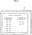
- FIG. 6 is a schematic diagram showing a display example of an abnormality determination result displayed on monitor 50.
- monitor 50 On monitor 50, a screen of the abnormality determination result is displayed.
- On the screen of the abnormality determination result for example, "OK” is displayed in the case of normal, and "NG” is displayed in a case where there is abnormality with respect to the microphone and the speaker.
- FIG. 6 “NG” is displayed for microphone mc6, and “OK” is displayed for the others with respect to microphones mc1 to mc6 and speakers sp1 and sp2. That is, in FIG. 6 , it is exemplified that microphone mc6 is determined to be abnormal.
- abnormality determination results of all of speakers sp1 and sp2 and microphones mc1 to mc6 of the abnormality test target are displayed, but some of the results may be omitted. That is, at least one abnormality determination result may be displayed among the abnormality test targets.
- BPF 28 that is connected to speaker sp2 and allows a signal of 3 to 6 kHz to pass may be switched to BPF 27 that allows a signal of 0 to 3 kHz to pass.
- BPF 27 that is connected to speaker sp1 and allows the signal of 0 to 3 kHz to pass may be switched to BPF 28 that allows the signal of 3 to 6 kHz to pass.
- audio processing system 5 may perform the abnormality test operation in a state in which BPFs 27 and 28 are switched.
- passband setting information is, for example, held in memory 12 of audio processing device 10.
- microphones mc1, mc2, and mc3 pick up the signal of 0 to 3 kHz output from speaker sp2, and no peaks appear in a case where all of microphones mc1, mc2, and mc3 are abnormal.
- speaker sp1 since at least one of microphones mc1, mc2, and mc3 collects the audio of 0 to 3 kHz output from speaker sp2 in a case where at least one of microphones mc1, mc2, and mc3 is not abnormal, the correlation value peak appears. Accordingly, audio processing system 5 can determine whether there is abnormality in microphones mc1, mc2, and mc3.
- microphones mc4, mc5, and mc6 pick up a signal of 4 to 6 kHz output from speaker sp1, and a peak does not appear when there is abnormality in all of microphones mc4, mc5, and mc6.
- audio processing system 5 determines whether there is abnormality in microphones mc4, mc5, and mc6 or not.
- controller 20 may set the passbands of BPFs 21 to 26 to be sequentially switched to 0 to 1 kHz so that the passbands of BPFs 21 to 26 corresponding to all of microphones mc1 to mc6 become 0 to 1 kHz.
- each passband of BPFs 21 to 26 corresponding to each of microphones mc1 to mc6 may be switched in a round robin manner.
- the setting of passband is performed by control device 40, for example.
- control device 40 sequentially changing each passband of BPFs 21 to 26 corresponding to each microphones mc1 to mc6, and carrying out the abnormality test on all microphones in the band of 0 to 1 kHz corresponding to the frequency band of the engine sound.
- audio processing system 5 can determine whether the audio of a band including the engine sound is collected, or whether there is no abnormality with respect to all microphones mc1 to mc6 by carrying out the abnormality test on the band of 0 to 1 kHz which is the main band of the engine sound for each of BPFs 21 to 26.
- speaker sp1 and microphones mc1, mc2, and mc3 are combined as an example of the first group for performing the abnormality test.
- speaker sp2 and microphones mc4, mc5, and mc6 are combined as an example.
- Combinations of the speaker and the plurality of microphones may be combined in any other way and may be optionally changed.
- one group subjected to the abnormality test may be formed by combining the speakers and the microphones that are close to each other.
- the magnitude of the correlation value calculated by correlation value calculators 15 and 16 depends on a signal level of the audio signal input by the microphones. Since each microphone inputs audio for abnormality test from the speaker, it is easier to input the audio signal output from the speaker when the microphone is located in a short distance from the speaker. Therefore, by forming groups by combining speakers and microphones in a distance close to each other, audio processing system 5 can easily determine the peak of the correlation value, and it is possible to improve the accuracy of the abnormality test.
- FIG. 7 is a schematic diagram showing an example of combination of a speaker and a plurality of microphones in a short distance from each other as a group for carrying out the abnormality test.
- Short distance means that each speaker and microphone device is located within a predetermined short distance range from each other.
- group A includes speaker sp1 and three microphones mc1, mc2, and mc5 in a close distance from speaker sp1.
- the speaker and the microphones of group A are disposed in first section 111.
- group B includes speaker sp2 and three microphones mc3, mc4, and mc6 in a close distance from speaker sp2.
- the speaker and the microphones of group B are disposed in second section 112.
- microphones mc1, mc2, and mc5 collect the audio emitted from speaker sp1 that is in a short distance from each other, and the abnormality test is carried out.
- microphones mc3, mc4, and mc6 collect audio emitted from speaker sp2 that is in a short distance from each other, and the abnormality test is carried out.
- audio processing device 10 can easily obtain the correlation value peak.
- the distances between the speaker and each microphone are approximately equalized, and it is expected that the variation of the correlation value based on the audio signals input from each microphone is reduced. Therefore, audio processing system 5 can improve the determination accuracy of the abnormality determination obtained by comparing the correlation value and threshold value th1.
- Audio processing system 5 can improve the accuracy of the abnormality test.
- FIG. 7 it is exemplified that the number of microphones assigned to one speaker as an abnormality test target in the same group is the same. Instead, different number of microphones may be assigned to one speaker as the abnormality test target in the same group for each section that is a short distance range from the speaker. This also applies to the case of FIG. 2 .
- audio processing system 5 including a speaker and a plurality of microphones disposed in one seat area is exemplified.
- Control device 40 may simultaneously (at the same timing) operate audio processing system 5 including speakers and a plurality of microphones disposed in two or more seat areas.
- audio processing system 5 performs the abnormality test distinctively for each area so that the sound emitted from the speaker and the audio collected by the plurality of microphones do not overlap in a plurality of areas.
- audio processing device 10 is provided for each area. That is, audio processing system 5 in Modification Examples 1 and 2 includes a plurality of audio processing devices 10 (see FIGS. 8 and 9 ).
- audio processing system 5 divides the audio band used for the abnormality test for each adjacent area and performs the abnormality test.
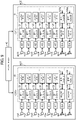
- FIG. 8 is a schematic diagram showing an example of setting of a band of BPF and setting of delay time in Modification Example 1.
- FIG. 8 some blocks of audio processing device 10 are shown, and some symbols are omitted.
- first area are1 near seat D1 the abnormality test is carried out using the audio with bands of 0 to 3 kHz and 3 kHz to 6 kHz as in the above-described embodiment.
- second area are2 near seat D2 adjacent to seat D1 the abnormality test is carried out using the audio with bands of 6 to 9 kHz and 9 to 12 kHz.
- speaker sp11 outputs audio of 6 to 9 kHz passed through BPF 127.
- BPFs 121 to 123 allow the audio of 6 to 7 kHz, 7 to 8 kHz, and 8 to 9 kHz respectively collected by microphones mc11 to mc13 to pass.
- speaker sp12 outputs the audio of 9 to 12 kHz passed through BPF 128.
- BPFs 124 to 126 allow the audio of 9 to 10 kHz, 10 to 11 kHz, and 11 to 12 kHz respectively collected by microphones mc14 to mc16 to pass.
- Control device 40 may set the band of BPF in each audio processing device 10 in first area are1 and second area are2 so as to handle the audio having different bands. For example, control device 40 sets a band of 0 to 6 kHz as the band of BPF of audio processing device 10 in first area are1. Control device 40 sets the band of 6 to 12 kHz as the band of BPF of audio processing device 10 in second area are2.
- audio processing system 5 can suppress the confusion of audio related to the abnormality test for each area, and it is possible to efficiently carry out the abnormality test of the speaker and the microphone.
- audio processing system 5 can suppress the influence of the abnormality test carried out in neighboring or adjacent areas.
- audio processing system 5 performs the abnormality test by shifting the timing for each adjacent area.
- FIG. 9 is a schematic diagram showing an example of setting a band of BPF and setting of delay time in Modification Example 2. As in Modification Example 1, in order to make the description easier to understand, in FIG. 9 , some blocks of audio processing device 10 are shown, and some symbols are omitted.
- second area are2 that is a second seat area
- delayers 137 and 138 are provided so that the timing of the sound output from speakers sp11 and sp12 is delayed by 100 msec respectively with respect to the timing of the sound output from speakers sp1 and sp2 in first area are1.
- Delayers 137 and 138 are included in CPU 11 of audio processing device 10 in second area are2.
- delaying 100 msec is exemplified in order to distinguish first area are1 and second area are2.
- this delay time is optional, and the delay time may be, for example, 200 msec, or 300 msec.
- delayers 37 and 38 are provided with respect to speakers sp1 and sp2 in first area are1 that is a first seat area.
- the set delay time is zero, so it is substantially the same as the case where a delayer is not provided.
- any delay time may be set with respect to delayers 37 and 38.
- the delay time set in delayers 137 and 138 on speakers sp11 and sp12 side in second area are2 may be set to be delayed according to the delay time of delayers 37 and 38. That is, the delay time of delayers 37 and 38 in first area are1 and the delay time of delayers 137 and 138 in second area are2 may be different as long as the correlation value peak is recognizable.
- Audio processing device 10 of second area are2 is provided with BPFs 127a and 128a connected to delayers 137 and 138.
- BPFs 127a and 128a have the same passband with BPFs 127 and 128 provided in audio processing device 10 in first area are1, different from Modification Example 1. That is, BPF 127a allows the audio data of 0 to 3 kHz to pass.
- BPF 128a allows the audio data of 3 to 6 kHz to pass.
- Control device 40 may set different delay times in first area are1 and second area are2 in each audio processing device 10 corresponding to each area. For example, control device 40 sets zero as the delay time for speakers sp1 and sp2 by audio processing device 10 handling the signals of the speakers and the microphones in first area are1. Control device 40 sets 100 ms as the delay time for speakers sp11 and sp12 by audio processing device 10 in second area are2.
- audio processing system 5 can suppress the confusion of audio related to the abnormality test for each area, and it is possible to efficiently carry out the abnormality test of the speaker and the microphone.
- audio processing system 5 can suppress the influence of the abnormality test carried out in neighboring or adjacent areas.
- Modification Examples 1 and 2 for example, during the maintenance or pre-flight preparation of an aircraft in an airport, it is possible to shorten the time required for the abnormality test of speakers and microphones executing ANC, and to efficiently carry out the abnormality test.
- Audio processing system 5 can carry out the abnormality test of the speakers and microphones in a plurality of areas simultaneously compared to a case where the abnormality test of the speakers and the microphones used in the ANC system is carried out with time difference in order by area. Therefore, audio processing system 5 can shorten the time required for the abnormality test, and improve the test efficiency.
- audio processing system 5 can separately recognize the audio for each area even though the audio of the abnormality test target leaks from the adjacent area to the microphone. Therefore, audio processing system 5 can recognize the audio of own area by excluding the audio of other areas. Audio processing system 5 can suppress the deterioration of accuracy of the abnormality test even when the abnormality test is carried out at the plurality of areas simultaneously (at once).
- speaker sp1 when detecting the abnormality using the audio, for example, speaker sp1 outputs audio.
- the plurality of microphones mc1 to mc3 collect the audio.
- the plurality of BPFs 21 to 23 allow the audio signals of the audio collected by the plurality of microphones mc1 to mc3 to pass any respective band included in 0 to band 3 kHz of the audio output from speaker sp1.
- the plurality of delayers 31 to 33 delay the audio signals passed through the plurality of BPFs 21 to 23 by the delay time corresponding to each bands of 10 msec, 20 msec, and 30 msec.
- Correlation value calculator 15 calculates the correlation value of the plurality of audio signals respectively delayed by the plurality of delayers 31 to 33 and the audio signal of the audio output from speaker sp1.
- Abnormality determinator 17 determines presence or absence of abnormality in the plurality of microphones mc1 to mc3 and speaker sp1 based on the calculated correlation value.
- Microphones mc1 to mc3 are an example of a microphone.
- BPFs 21 to 23 are an example of a first filter.
- Delayers 31 to 33 are an example of a first delayer.
- Abnormality determinator 17 is an example of a determinator. Each band of 0 to 1 kHz, 1 to 2 kHz, and 2 to 3 kHz is an example of a first band.
- the correlation value peak appears at different time positions for each microphone. Therefore, the time position where the correlation value peak appears indicates whether there is abnormality in the speaker or the plurality of microphones of the abnormality test target.
- Audio processing system 5 can determine which one of the speaker or the plurality of microphones of the abnormality test target is abnormal by using the correlation value at the time corresponding to the delay times of each of delayers 31 to 33 even in a case where some of the correlation value is not detected.
- Audio processing system 5 can carry out the abnormality test at once with respect to the plurality of microphones even though there are a plurality of microphones of the abnormality test target, improve the test efficiency, and shorten the time required for the abnormality test. Therefore, audio processing system 5 can shorten the time required for, for example, maintenance and pre-flight preparation of an aircraft.
- audio processing system 5 Since audio processing system 5 is used in the ANC system, it can be said that it is also a noise cancellation system. In audio processing system 5, since audio processing device 10 diagnoses presence or absence of abnormality in the microphones and the speakers included in audio processing system 5, it can be said that the audio processing device 10 has the self-diagnosis function related to the abnormality test.
- the bands of the plurality of BPFs 21 to 23 may be different bands 0 to 1 kHz, 1 to 2 kHz and 2 to 3 kHz, respectively.
- audio processing system 5 can improve the determination accuracy of the presence or absence of abnormality.
- audio processing system 5 can reduce the processing load related to the abnormality determination.
- Audio processing system 5 may include monitor 50 that displays information on the presence or absence of the abnormality of at least one of the plurality of microphones mc1 to mc3 and speaker sp1 determined by abnormality determinator 17.
- Monitor 50 is an example of display.
- a user can visually recognize the presence or absence of abnormality in the microphones and speakers.
- Speaker sp1 may output audio of a predetermined band.
- BPFs 21 to 23 may allow the audio signal of the band included in the predetermined band to pass.
- Audio processing system 5 can determine the presence or absence of abnormality by collecting the audio of any band with respect to each of microphones mc1 to mc6. Therefore, audio processing system 5 can suppress the noise emitted from the target to be muffled.
- the predetermined band may be a band including 0 to 1 kHz.
- Audio processing system 5 can collect the audio of the band including 0 to 1 kHz which is the band of the engine sound, and can determine the presence or absence of abnormality with respect to each of microphones mc1 to mc6. It is possible to appropriately carry out the abnormality test of the plurality of microphones and speakers used in the ANC system such as an aircraft. Audio processing system 5 can output audio of an opposite phase from a speaker with respect to the engine sound of an aircraft, and suppress the engine sound around the user.
- Audio processing system 5 may include a plurality of BPFs 27 and 28 that allow the audio signal of 0 to 3 kHz and 3 to 6 kHz (plurality of different bands) to pass. Speakers sp1 and sp2 may input the audio signal passed through BPFs 27 and 28 respectively and output audio based on the audio signal. Microphones mc1 to 3 which are part of the plurality of microphones mc1 to mc6 and speaker sp1 which is a part of the plurality of speakers sp1 and sp2 may be combined to form a first group.
- microphones mc4 to 6 which are a part of the plurality of microphones mc1 to mc6 and speaker sp2 which is a part of the plurality of speakers sp1 and sp2 may be combined to form a second group.
- Bands 0 to 1 kHz, 1 to 2 kHz, and 2 to 3 kHz of BPFs 21 to 23 corresponding to microphones mc1 to mc3 belonging to the first group may be included in the band 0 to 3 kHz of BPF 27 corresponding to speaker sp1 belonging to the first group.
- Bands 3 to 4 kHz, 4 to 5 kHz, and 5 to 6 kHz of BPFs 24 to 26 corresponding to microphones mc4 to mc6 belonging to the second group may be included in the band 4 to 6 kHz of BPF 28 corresponding to speaker sp2 belonging to the second group.
- BPFs 27 and 28 are an example of a second filter.
- Speaker sp1 is an example of a first speaker.
- Speaker sp2 is an example of a second speaker.
- Audio processing system 5 even when the plurality of speakers sp1 and sp2 output the audio for the abnormality test simultaneously, it is possible to input and detect each audio input by microphones mc1 to mc3 and mc4 to mc6 and BPFs 21 to 23 and 24 to 26 by separating the output band of the audio for the abnormality test. Audio processing system 5 can carry out the abnormality test of the plurality of speakers and the plurality of microphones at once even when the plurality of speakers make sound simultaneously. Accordingly, audio processing system 5 can improve the test accuracy of the abnormality test and promptly carry out the abnormality test.
- Audio processing system 5 may include control device 40 that sets parameters of audio processing device 10.
- control device 40 may switch and set band 0 to 3 kHz of BPF 27 corresponding to speaker sp1 belonging to the first group and band 3 to 6 kHz of BPF 28 corresponding to speaker sp2 belonging to the second group.
- audio processing system 5 switches information on the band of BPF 27 and information on the band of BPF 28.
- Microphones mc1 to mc3 input the audio output from speaker sp2 and the abnormality test is carried out again, so that audio processing system 5 can determine whether speaker sp1 is abnormal or all of the plurality of microphones mc1 to mc3 are abnormal.
- audio processing system 5 can determine the abnormality even when there is abnormality in some of speakers.
- the first group may include speaker sp1 and a plurality of microphones mc1, mc2, and mc5 disposed within a predetermined distance from speaker sp1.
- the second group may include speaker sp2 and a plurality of microphones mc3, mc4, and mc6 disposed within a predetermined distance from speaker sp2. That is, a group of abnormality test target may be formed by combining these groups.
- Audio processing system 5 since microphones mc1, mc2, and mc5 collect audio emitted from speaker sp1 existing in a short distance and the abnormality test is carried out, it is easy to collect the audio emitted from speaker sp1. Audio processing system 5 can easily determine the peak of the correlation value and improve the accuracy of the abnormality test.
- Audio processing system 5 may include a plurality of microphones, a speaker, and audio processing device 10 in a plurality of areas including first area are1 and second area are2. At least one group including a plurality of microphones and a speaker may be formed in each area.
- Control device 40 may set a band 0 to 6 kHz of BPFs 21 to 26 corresponding to microphones mc1 to mc6 provided in first area are1 and a band 0 to 6 kHz of BPFs 27 and 28 corresponding to speakers sp1 and sp2 provided in first area are1 as a band included in a predetermined band (0 to 6 kHz, for example).
- Control device 40 may set a band 6 to 12 kHz of BPFs 121 to 126 corresponding to microphones mc11 to mc16 provided in second area are2 and a band 6 to 12 kHz of BPFs 127 and 128 corresponding to speakers sp11 and sp12 provided in second area are2 as a band included in a predetermined band (6 to 12 kHz, for example) different from the predetermined band.
- audio processing system 5 can, for example, recognize the audio emitted by a speaker of another area even if the abnormality test for the plurality of microphones and speakers used in the ANC for each adjacent area is carried out simultaneously. That is, audio processing system 5 can determine the abnormality by excluding the audio signal emitted by a speaker of other areas among the audio signals input by the microphone in the areas.
- Audio processing device 10 related to second area are2 may include delayers 137 and 138 that delay the audio signal input into speakers sp11 and sp12 provided in second area are2.
- Delayers 137 and 138 are an example of a second delayer.
- audio processing system 5 can, for example, recognize the audio emitted by a speaker of another area even if the abnormality test of the plurality of microphones and speakers used in the ANC for each adjacent area is carried out simultaneously. That is, audio processing system 5 can determine the abnormality by excluding the audio signal emitted by a speaker of other areas among the audio signals input by the microphone in the areas.
- the audio signals output from speakers sp1 and sp2 in first area are1 may be delayed using a delayer, and may not be delayed.
- passbands of BPFs 21 to 26 are different to each other in audio processing system 5, but it is not limited to this. That is, the passbands of BPFs 21 to 26 may be any band included in the band of the audio output from speaker sp1 or speaker sp2. For example, all of the passbands of BPF 21 to BPF 23 may be 0 to 3 kHz which is the same as the passband of speaker sp1.
- the passbands of BPF 21 to BPF 22 may be set to 0 to 2 kHz and 1 to 3 kHz, each partially overlapping.
- audio processing system 5 can determine the abnormality using the correlation value.
- the correlation value peak appears at different time positions for each band in audio processing system 5.
- the audio signals relatively delayed by delayers 31 to 33 are added, the level of added audio signal becomes relatively small at the time positions other than the correlation value peak (see FIG. 4A .
- the difference of the correlation value at the time position (10 ms, 20 ms, 30 ms, for example) of the correlation value peak and the time position (time position other than 10 ms, 20 ms, 30 ms, for example) other than the correlation value peak increases.
- audio processing system 5 can improve the determination accuracy of the presence or absence of abnormality. By making the band of the audio signal of each microphone different, the band of the test target corresponding to a single microphone is narrowed, and audio processing system 5 can reduce the processing load related to the abnormality determination.
- the abnormality test is carried out for six microphones (four reference microphones and two error microphones) and two speakers used in audio processing system 5 as the ANC system.
- the number of microphones and speakers is not limited to this, and any combination can be used.
- audio processing system 5 forms a group by combining one speaker and three microphones, and performs an abnormality test. Audio processing system 5 may perform the abnormality test for all microphones (six) with one speaker. Three or more groups of abnormality test target may be formed.
- the microphone and the speaker of audio processing system 5 are installed in an aircraft, but it may be installed in vehicles (automobile, ship, rocket and alike) other than the aircraft.
- reference microphone and the error microphone are included in audio processing system 5, but either one may be omitted.
- reference microphone can be omitted.
- the audio data other than white noise may be input.
- the audio data with a predetermined audio band may be input into BPFs 27 and 28 instead of the audio data with no defined band such as white noise.
- the audio data with the predetermined band may be a band wider than the band (0 to 6 kHz, for example) in which the abnormality test for the microphone and the speaker is carried out.
- one area is one seat area, but one area may include two or more seat areas.
- the abnormality test for speakers and microphones is carried out during the maintenance or pre-flight preparation when the aircraft is parked, but the abnormality test may be carried out during aircraft flight.
- audio processing system 5 may avoid the band (500 Hz to 1 kHz, for example) of the engine sound and may output an audio signal from the speaker. It is because the engine sound always presents during the flight. The processing load of audio processing device 10 related to the abnormality test is reduced.
- the processor may be physically configured in any way. With a programmable processor, processing contents can be changed by program change, and it is possible to increase the design flexibility of the processor.
- the processor may be configured of a single semiconductor chip, and may be physically configured of a plurality of semiconductor chips. In the case of the plurality of semiconductor chips, each control in the first embodiment may be realized by separate semiconductor chips. In this case, it can be considered that a single processor is composed of those plurality of semiconductor chips.
- the processor may be configured of a member (such as capacitor) having a function different from that of the semiconductor chip.
- a single semiconductor chip may be configured so as to realize the functions of the processor and other functions.
- the present disclosure is useful for an audio processing system, an audio processing device, and an audio processing method that can shorten the time required for the abnormality test of a speaker and a microphone and determine presence or absence of abnormality even in a case where there are a plurality of microphones and speakers in a vehicle.
Landscapes
- Engineering & Computer Science (AREA)
- Physics & Mathematics (AREA)
- Acoustics & Sound (AREA)
- Signal Processing (AREA)
- Health & Medical Sciences (AREA)
- Otolaryngology (AREA)
- General Health & Medical Sciences (AREA)
- Multimedia (AREA)
- Computational Linguistics (AREA)
- Quality & Reliability (AREA)
- Audiology, Speech & Language Pathology (AREA)
- Human Computer Interaction (AREA)
- Circuit For Audible Band Transducer (AREA)
- Fittings On The Vehicle Exterior For Carrying Loads, And Devices For Holding Or Mounting Articles (AREA)
Claims (16)
- Audioverarbeitungsvorrichtung (10), die ausgestaltet ist, ein Vorliegen oder eine Abwesenheit einer Anomalie in einem Lautsprecher (sp1, sp2, sp11, sp12) und mehreren Mikrofonen (mc1-mc6, mc11-mc16) zu bestimmen,wobei der Lautsprecher (sp1, sp2, sp11, sp12) ausgestaltet ist, ein Lautsprechersignal zu empfangen,die mehreren Mikrofone (mc1-mc6, mc11-mc16) ausgestaltet sind, die Audioausgabe von dem Lautsprecher (sp1, sp2, sp11, sp12) aufzunehmen,wobei die Audioverarbeitungsvorrichtung (10) umfasst:mehrere erste Filter (21-26, 121-126), wobei jeder Filter (21-26, 121-126) mit einem entsprechenden Mikrofon (mc1-mc6, mc11-mc16) der mehreren Mikrofone (mc1-mc6, mc11-mc16) assoziiert ist und ausgestaltet ist, in einem jeweiligen ersten Band durchzulassen, das in einem Band der Audioausgabe von dem Lautsprecher (sp1, sp2, sp11-sp22) enthalten ist,mehrere erste Verzögerer (31-33, 34-36), wobei jeder Verzögerer (31-33, 34-36) mit einem entsprechenden Filter (21-26, 121-126) von den mehreren Filtern (21-26, 121-126) assoziiert ist und ausgestaltet ist, das Audiosignal, das durch den entsprechenden Filter (21-26, 121-126) der mehreren ersten Filter (21-26, 121-126) durchgelassen wurde, um eine jeweilige Verzögerungszeit (τ) zu verzögern, die sich von Verzögerungszeiten (τ) von anderen der mehreren ersten Verzögerer (31-33, 34-36) unterscheidet, undeinen ersten Addierer (13, 14), der ausgestaltet ist, die Audiosignale zu addieren, die von den mehreren ersten Verzögern (31-33, 34-36) ausgegeben wurden,einen ersten Korrelationswertberechner (15, 16), der ausgestaltet ist, Korrelationswerte des Signals, das von dem Addierer (13, 14) ausgegeben wurde, und des Lautsprechersignals für jedes Timing entsprechend den Verzögerungszeiten (τ) der mehreren ersten Verzögerer (31-33, 34-36) zu berechnen,wobei ein Bestimmer (17, 18) das Vorliegen oder die Abwesenheit einer Anomalie in den mehreren Mikrofonen (mc1-mc6, mc11-mc16) und dem Lautsprecher (sp1, sp2, sp11, sp12) auf Basis der berechneten Korrelationswerte bestimmt.
- Audioverarbeitungssystem (5), mit:einem Lautsprecher (sp1, sp2, sp11, sp12), der ausgestaltet ist, Audio auszugeben,mehreren Mikrofonen (mc1-mc6, mc11-mc16), die ausgestaltet sind, das Audio aufzunehmen, undder Audioverarbeitungsvorrichtung (10) nach Anspruch 1, die ausgestaltet ist, das Vorliegen oder die Abwesenheit einer Anomalie in den mehreren Mikrofonen (mc1-mc6, mc11-mc16) und dem Lautsprecher (sp1, sp2, sp11, sp12) auf Basis des Audios zu bestimmen, das durch die Mikrofone (mc1-mc6, mc11-mc16) aufgenommen wurde.
- Audioverarbeitungssystem (5) nach Anspruch 2,
wobei Bänder der mehreren ersten Filter (21-26, 121-126) unterschiedlich voneinander sind. - Audioverarbeitungssystem (5) nach Anspruch 3, ferner mit:
einer Anzeige (50), die ausgestaltet ist, Information hinsichtlich des Vorliegens oder der Abwesenheit einer Anomalie in wenigstens einem der mehreren Mikrofone (mc1-mc6, mc11-mc16) und dem Lautsprecher (sp1, sp2, sp11, sp12) anzuzeigen, die durch den Bestimmer (17, 18) bestimmt wurde. - Audioverarbeitungssystem (5) nach Anspruch 3,
wobei der Lautsprecher (sp1, sp2, sp11, sp12) ausgestaltet ist, Audio in einem vorbestimmten Band auszugeben, das ein Band von 0 bis 1 kHz umfasst. - Audioverarbeitungssystem (5) nach Anspruch 3, ferner mit:mehreren zweiten Filtern (27, 28, 127, 128, 127a, 128a), die ausgestaltet sind, Audiosignale mehrerer unterschiedlicher zweiter Bänder durchzulassen,wobei der Lautsprecher (sp1, sp2, sp11, sp12) mehrere Lautsprecher (sp1, sp2, sp11, sp12) umfasst,wobei die mehreren Lautsprecher (sp1, sp2, sp11, sp12) ausgestaltet sind, Audiosignale einzugeben, die jeweilig durch die mehreren zweiten Filter (27, 28, 127, 128, 127a, 128a) hindurchgelassen wurden, und Audio der Audiosignale auszugeben,wobei jeder Teil der mehreren Mikrofone (mc1-mc6, mc11-mc16) und jeder Teil der mehreren Lautsprecher (sp1, sp2, sp11, sp12) kombiniert wird, um eine Gruppe mit einer ersten Gruppe und einer zweiten Gruppe zu bilden,wobei das erste Band des ersten Filters (21-23, 121-123) entsprechend einem Mikrofon (mc1-mc3, mc11-mc13), das zu ersten Gruppe gehört, in dem zweiten Band des zweiten Filters (27, 127, 127a, 128a) entsprechend einem ersten Lautsprecher (sp1, sp11) enthalten ist, der zu der ersten Gruppe gehört, undwobei das erste Band des ersten Filters (24, 26, 124-126) entsprechend einem Mikrofon (mc4-mc6, mc14-mc16), das zu der zweiten Gruppe gehört, in dem zweiten Band des zweiten Filters (28, 128, 128a) entsprechend einem zweiten Lautsprecher (sp2, sp12) enthalten ist, der zu der zweiten Gruppe gehört.
- Audioverarbeitungssystem (5) nach Anspruch 6,wobei die erste Gruppe den ersten Lautsprecher (sp1, sp11) und die mehreren Mikrofone (mc1-mc3, mc11-mc13) umfasst, die innerhalb einer vorbestimmten Entfernung von dem ersten Lautsprecher (sp1, sp11) angeordnet sind, undwobei die zweite Gruppe den zweiten Lautsprecher (sp2, sp12) und die mehreren Mikrofone (mc4-mc6, mc14-mc16) umfasst, die innerhalb einer vorbestimmten Entfernung von dem zweiten Lautsprecher (sp2, sp12) angeordnet sind.
- Audioverarbeitungssystem (5) nach Anspruch 6, ferner mit:einer Steuervorrichtung (40), die ausgestaltet ist, Parameter der Audioverarbeitungsvorrichtung (10) einzustellen,wobei die mehreren Mikrofone (mc1-mc6, mc11-mc16), der Lautsprecher (sp1, sp2, sp11, sp12) und die Audioverarbeitungsvorrichtung (10) in jedem von mehreren Bereichen (are1, are2) mit einem ersten Bereich (are1) und einem zweiten Bereich (are2) vorgesehen sind,wobei wenigstens eine Gruppe mit den mehreren Mikrofonen (mc1-mc6, mc11-mc16) und den Lautsprechern (sp1, sp2, sp11, sp12) für jeden der Bereiche (are1, are2) gebildet ist,wobei die Steuervorrichtung (40) ausgestaltet ist, das erste Band des ersten Filters (21-26) entsprechend zu den Mikrofonen (mc11-mc6), die in dem ersten Bereich (are1) vorgesehen sind, und das zweite Band des zweiten Filters (27, 28) entsprechend dem Lautsprecher (sp1, sp2), der in dem ersten Bereich (are1) vorgesehen ist, als ein Band einzustellen, das in einem vorbestimmten dritten Band enthalten ist, undwobei die Steuervorrichtung (40) ausgestaltet ist, das erste Band des ersten Filters (121-126) entsprechend zu den Mikrofonen (mc11-mc16), die in dem zweiten Bereich (are2) vorgesehen sind, und das zweite Band des zweiten Filters (127, 128, 127a, 128a) entsprechend dem Lautsprecher (sp11, sp12), der in dem zweiten Bereich (are2) vorgesehen ist, als ein Band einzustellen, das in einem vorbestimmten vierten Band enthalten ist, das sich von dem dritten Band unterscheidet.
- Audioverarbeitungssystem (5) nach Anspruch 6, ferner mit:eine Steuervorrichtung (40), die ausgestaltet ist, Parameter der Audioverarbeitungsvorrichtung (10) einzustellen,wobei die mehreren Mikrofone (mc1-mc6, mc11-mc16), der Lautsprecher (sp1, sp2, sp11, sp12) und die Audioverarbeitungsvorrichtung (10) in jedem von mehreren Bereichen (are1, are2) mit einem ersten Bereich (are1, are2) und einem zweiten Bereich (are1, are2) vorgesehen sind,wobei wenigstens eine Gruppe mit den mehreren Mikrofonen (mc1-mc6, mc11-mc16) und dem Lautsprecher (sp1, sp2, sp11, sp12) für jeden der Bereiche (are1, are2) gebildet ist, undwobei die Audioverarbeitungsvorrichtung (10) die zu dem zweiten Bereich (are2) gehört, einen zweiten Verzögerer (137, 138) aufweist, der ausgestaltet ist, ein Audiosignal zu verzögern, das in den Lautsprecher (sp11, sp12) einzugeben ist, der in dem zweiten Bereich (are2) vorgesehen ist.
- Audioverarbeitungssystem (5) nach Anspruch 6, ferner mit:einer Steuervorrichtung (40), die ausgestaltet ist, Parameter der Audioverarbeitungsvorrichtung (10) einzustellen,wobei die Steuereinrichtung (40) in einem Fall, bei dem ein Korrelationswert, der durch den ersten Korrelationswertberechner (15, 16) berechnet wurde, zu einer Zeit entsprechend jeder der Verzögerungszeiten, die durch den ersten Verzögerer (31-33, 34-36) verzögert wird, geringer ist als ein Schwellenwert, ausgestaltet ist, das zweite Band des zweiten Filters (27, 127, 127a) entsprechend zu dem ersten Lautsprecher (sp1, sp11), der zu der ersten Gruppe gehört, und das zweite Band des zweiten Filters (28, 128, 128a) entsprechend zu dem zweiten Lautsprecher (sp2, sp12), der zu der zweiten Gruppe gehört, auszutauschen und einzustellen.
- Audioverarbeitungssystem (5) nach Anspruch 10, ferner mit:einer Steuervorrichtung (40), die ausgestaltet ist, Parameter der Audioverarbeitungsvorrichtung (10) einzustellen,wobei die mehreren Mikrofone (mc1-mc6, mc11-mc16), der Lautsprecher (sp1, sp2, sp11, sp12) und die Audioverarbeitungsvorrichtung (10) in jedem von mehreren Bereichen (are1, are2) mit einem ersten Bereich (are1, are2) und einem zweiten Bereich (are1, are2) vorgesehen sind,wobei wenigstens eine Gruppe mit den mehreren Mikrofonen (mc1-mc6, mc11-mc16) und dem Lautsprecher (sp1, sp2, sp11, sp12) für jeden der Bereiche (are1, are2) gebildet ist, undwobei die Steuervorrichtung (40) ausgestaltet ist, das erste Band des ersten Filters (21-26) entsprechend der Mikrofone (mc1-mc6), die in dem ersten Bereich (are1) vorgesehen sind, und das zweite Band des zweiten Filters (27, 28) entsprechend dem Lautsprecher (sp1, sp2), der in dem ersten Bereich (are1) vorgesehen ist, als ein Band einzustellen, das in einem vorbestimmten dritten Band enthalten ist, undwobei die Steuervorrichtung (40) ausgestaltet ist, das erste Band des ersten Filters (121-126) entsprechend den Mikrofonen (mc11-mc16), die in dem zweiten Bereich (are2) vorgesehen sind, und das zweite Band des zweiten Filters (127, 128, 127a, 128a) entsprechend dem Lautsprecher (sp11, sp12), der in dem zweiten Bereich (are2) vorgesehen ist, als ein Band einzustellen, das in einem vorbestimmten vierten Band enthalten ist, das sich von dem dritten Band unterscheidet.
- Audioverarbeitungssystem (5) nach Anspruch 10, ferner mit:eine Steuervorrichtung (40), die ausgestaltet ist, Parameter der Audioverarbeitungsvorrichtung (10) einzustellen,wobei die mehreren Mikrofone (mc1-mc6, mc11-mc16), der Lautsprecher (sp1, sp2, sp11, sp12) und die Audioverarbeitungsvorrichtung (10) in jedem von mehreren Bereichen (are1, are2) mit einem ersten Bereich (are1) und einem zweiten Bereich (are2) vorgesehen sind,wobei wenigstens eine Gruppe mit den mehreren Mikrofonen (mc1-mc6, mc11-mc16) und dem Lautsprecher (sp1, sp2, sp11, sp12) für jeden der Bereiche gebildet ist, undwobei die Audioverarbeitungsvorrichtung (10) die zu dem zweiten Bereich (are2) gehört, einen zweiten Verzögerer (137, 138) aufweist, der ausgestaltet ist, ein Audiosignal zu verzögern, das in den Lautsprecher (sp1, sp12) einzugeben ist, der in dem zweiten Bereich (are2) vorgesehen ist.
- Audioverarbeitungssystem (5) nach Anspruch 10,wobei die erste Gruppe den ersten Lautsprecher (sp1, sp11) und die mehreren Mikrofone (mc1-mc3, mc11-mc13) umfasst, die innerhalb einer vorbestimmten Entfernung von dem ersten Lautsprecher (sp1, sp11) angeordnet sind, undwobei die zweite Gruppe den zweiten Lautsprecher (sp2, sp12) und die mehreren Mikrofone (mc4-mc6, mc14-mc16) umfasst, die innerhalb einer vorbestimmten Entfernung von dem zweiten Lautsprecher (sp2, sp12) angeordnet sind.
- Audioverarbeitungssystem (5) nach Anspruch 13, ferner mit:einer Steuervorrichtung (40), die ausgestaltet ist, Parameter der Audioverarbeitungsvorrichtung (10) einzustellen,wobei die mehreren Mikrofone (mc1-mc6, mc11-mc16), der Lautsprecher (sp1, sp2, sp11, sp12) und die Audioverarbeitungsvorrichtung (10) in jedem von mehreren Bereichen (are1, are2) mit einem ersten Bereich (are1, are2) und einem zweiten Bereich (are1, are2) vorgesehen sind,wobei wenigstens eine Gruppe mit den mehreren Mikrofonen (mc1-mc6, mc11-mc16) und dem Lautsprecher (sp1, sp2, sp11, sp12) für jeden der Bereiche (are1, are2) gebildet ist,wobei die Steuervorrichtung (40) ausgestaltet ist, das erste Band des ersten Filters (21-26) entsprechend der Mikrofone (mc1-mc6), die in dem ersten Bereich (are1) vorgesehen sind, und das zweite Band des zweiten Filters (27, 28) entsprechend dem Lautsprecher (sp1, sp2), der in dem ersten Bereich (are1) vorgesehen ist, als ein Band einzustellen, das in einem vorbestimmten dritten Band enthalten ist, undwobei die Steuervorrichtung (40) ausgestaltet ist, das erste Band des ersten Filters (121-126) entsprechend den Mikrofonen (mc11-mc16), die in dem zweiten Bereich (are2) vorgesehen sind, und das zweite Band des zweiten Filters (127, 128, 127a, 128a) entsprechend dem Lautsprecher (sp11, sp12), der in dem zweiten Bereich (are2) vorgesehen ist, als ein Band einzustellen, das in einem vorbestimmten vierten Band enthalten ist, das sich von dem dritten Band unterscheidet.
- Audioverarbeitungssystem (5) nach Anspruch 13, ferner mit:eine Steuervorrichtung (40), die ausgestaltet ist, Parameter der Audioverarbeitungsvorrichtung (10) einzustellen,wobei die mehreren Mikrofone (mc1-mc6, mc11-mc16), der Lautsprecher (sp1, sp2, sp11, sp12) und die Audioverarbeitungsvorrichtung (10) in jedem von mehreren Bereichen (are1, are2) mit einem ersten Bereich (are1, are2) und einem zweiten Bereich (are1, are2) vorgesehen sind,wobei wenigstens eine Gruppe mit den mehreren Mikrofonen (mc1-mc6, mc11-mc16) und dem Lautsprecher (sp1, sp2, sp11, sp12) für jeden der Bereiche (are1, are2) gebildet ist, undwobei die Audioverarbeitungsvorrichtung (10) die zu dem zweiten Bereich (are2) gehört, einen zweiten Verzögerer (137, 138) aufweist, der ausgestaltet ist, ein Audiosignal zu verzögern, das in den Lautsprecher (sp11, sp12) einzugeben ist, der in dem zweiten Bereich (are2) vorgesehen ist.
- Audioverarbeitungsverfahren zum Bestimmen eines Vorliegens oder einer Abwesenheit einer Anomalie in einem Lautsprecher (sp1, sp2, sp11, sp12) und mehreren Mikrofonen (mc1-mc6, mc11-mc16), wobei der Lautsprecher (sp1, sp2, sp11, sp12) ein Lautsprechersignal empfängt,die mehreren Mikrofone (mc1-mc6, mc11-mc16) die Audioausgabe von dem Lautsprecher (sp1, sp2, sp11, sp12) aufnehmen,wobei der Verfahren umfasst:mehrere erste Filter (21-26, 121-126), die jeder mit einem entsprechenden Mikrofon (mc1-mc6, mc11-mc16) der mehreren Mikrofone (mc1-mc6) assoziiert sind, wobei jeder Filter der mehreren Filter in einem jeweiligen ersten Band durchlässt, das in einem Band der Audioausgabe von dem Lautsprecher (sp1, sp2, sp11, sp12) enthalten ist,Verzögern des Audiosignals, das durch den entsprechenden Filter (21-26, 121-126) der mehreren ersten Filter (21-26, 121-126) durchgelassen wurde, durch mehrere erste Verzögerer (31-33, 34-36) um eine jeweilige Verzögerungszeit (τ), die sich von Verzögerungszeiten (τ) von anderen der mehreren ersten Verzögerer (31-33, 34-36) unterscheidet, wobei jeder Verzögerer (31-33, 34-36) mit einem entsprechenden Filter (21-26, 121-126) von den mehreren Filtern (21-26, 121-126) assoziiert ist,Addieren der Audiosignale, die von den mehreren ersten Verzögerer (31-33, 34-36) ausgegeben wurden, durch einen Addierer (13, 14),Berechnen (S2) von Korrelationswerten des Signals, das von dem Addierer (13, 14) ausgegeben wurde, und des Lautsprechersignals für jedes Timing entsprechend der Verzögerungszeiten (τ) der mehreren ersten Verzögerer (31-33, 34-36),wobei ein Bestimmen (S3-S8) eines Vorliegens oder einer Abwesenheit einer Anomalie in den mehreren Mikrofonen (mc1-mc6, mc11-mc16) und dem Lautsprecher (sp1, sp2, sp11, sp12) auf den berechneten Korrelationswerten basiert.
Priority Applications (1)
| Application Number | Priority Date | Filing Date | Title |
|---|---|---|---|
| EP22177919.2A EP4090050A1 (de) | 2016-05-27 | 2017-04-19 | Audioverarbeitungssystem, audioverarbeitungsvorrichtung und audioverarbeitungsverfahren |
Applications Claiming Priority (2)
| Application Number | Priority Date | Filing Date | Title |
|---|---|---|---|
| JP2016106422A JP6620675B2 (ja) | 2016-05-27 | 2016-05-27 | 音声処理システム、音声処理装置及び音声処理方法 |
| PCT/JP2017/015639 WO2017203900A1 (ja) | 2016-05-27 | 2017-04-19 | 音声処理システム、音声処理装置及び音声処理方法 |
Related Child Applications (2)
| Application Number | Title | Priority Date | Filing Date |
|---|---|---|---|
| EP22177919.2A Division-Into EP4090050A1 (de) | 2016-05-27 | 2017-04-19 | Audioverarbeitungssystem, audioverarbeitungsvorrichtung und audioverarbeitungsverfahren |
| EP22177919.2A Division EP4090050A1 (de) | 2016-05-27 | 2017-04-19 | Audioverarbeitungssystem, audioverarbeitungsvorrichtung und audioverarbeitungsverfahren |
Publications (3)
| Publication Number | Publication Date |
|---|---|
| EP3468232A1 EP3468232A1 (de) | 2019-04-10 |
| EP3468232A4 EP3468232A4 (de) | 2019-06-19 |
| EP3468232B1 true EP3468232B1 (de) | 2022-07-27 |
Family
ID=60412258
Family Applications (2)
| Application Number | Title | Priority Date | Filing Date |
|---|---|---|---|
| EP17802499.8A Active EP3468232B1 (de) | 2016-05-27 | 2017-04-19 | Audioverarbeitungssystem, audioverarbeitungsvorrichtung und audioverarbeitungsverfahren |
| EP22177919.2A Withdrawn EP4090050A1 (de) | 2016-05-27 | 2017-04-19 | Audioverarbeitungssystem, audioverarbeitungsvorrichtung und audioverarbeitungsverfahren |
Family Applications After (1)
| Application Number | Title | Priority Date | Filing Date |
|---|---|---|---|
| EP22177919.2A Withdrawn EP4090050A1 (de) | 2016-05-27 | 2017-04-19 | Audioverarbeitungssystem, audioverarbeitungsvorrichtung und audioverarbeitungsverfahren |
Country Status (4)
| Country | Link |
|---|---|
| US (1) | US10595125B2 (de) |
| EP (2) | EP3468232B1 (de) |
| JP (1) | JP6620675B2 (de) |
| WO (1) | WO2017203900A1 (de) |
Families Citing this family (15)
| Publication number | Priority date | Publication date | Assignee | Title |
|---|---|---|---|---|
| EP3402219B1 (de) | 2016-10-14 | 2023-05-03 | Yamaha Corporation | Audioein-/-ausgabemodul, notfallmeldemodul und fehlererkennungsverfahren |
| US10687159B2 (en) * | 2018-03-12 | 2020-06-16 | Panasonic Intellectual Property Management Co., Ltd. | Noise reduction device, noise reduction system, and fault detection method for noise reduction device |
| US10924873B2 (en) * | 2018-05-30 | 2021-02-16 | Signify Holding B.V. | Lighting device with auxiliary microphones |
| CN109121035B (zh) * | 2018-08-30 | 2020-10-09 | 歌尔科技有限公司 | 耳机异常处理方法、耳机、系统及存储介质 |
| JP6806123B2 (ja) * | 2018-11-01 | 2021-01-06 | ヤマハ株式会社 | 故障検出装置、音声入出力モジュール、及び故障検出方法 |
| DE102019205534A1 (de) * | 2019-04-17 | 2020-10-22 | Robert Bosch Gmbh | Verfahren zum Betreiben eines insbesondere wenigstens teilweise automatisierten Fahrzeugs |
| US10873809B2 (en) * | 2019-05-24 | 2020-12-22 | Bose Corporation | Dynamic control of multiple feedforward microphones in active noise reduction devices |
| CN110337055A (zh) * | 2019-08-22 | 2019-10-15 | 百度在线网络技术(北京)有限公司 | 音箱的检测方法、装置、电子设备及存储介质 |
| CN111586547B (zh) * | 2020-04-28 | 2022-05-06 | 北京小米松果电子有限公司 | 音频输入模组的检测方法及装置、存储介质 |
| US11297452B2 (en) * | 2020-08-14 | 2022-04-05 | Subaru Corporation | Inspection system and inspection method |
| US11451915B2 (en) * | 2020-12-30 | 2022-09-20 | Silentium Ltd. | Apparatus, system, and method of testing an acoustic device |
| US11843927B2 (en) * | 2022-02-28 | 2023-12-12 | Panasonic Intellectual Property Management Co., Ltd. | Acoustic control system |
| JP7797927B2 (ja) * | 2022-03-14 | 2026-01-14 | 富士フイルムビジネスイノベーション株式会社 | 情報処理装置及びプログラム |
| CN117098054A (zh) * | 2022-05-13 | 2023-11-21 | 深圳市三诺数字科技有限公司 | 麦克风和扬声器设备异常检测方法及装置 |
| WO2025192552A1 (ja) * | 2024-03-11 | 2025-09-18 | 住友重機械工業株式会社 | 作業機械、作業機械システム |
Family Cites Families (15)
| Publication number | Priority date | Publication date | Assignee | Title |
|---|---|---|---|---|
| JPH11167383A (ja) * | 1997-12-03 | 1999-06-22 | Alpine Electron Inc | 適応等化システムの接続確認方式 |
| AU2003264360A1 (en) * | 2002-08-30 | 2004-04-08 | Nsk Ltd. | Method and device for monitoring status of mechanical equipment and abnormality diagnosing device |
| JP4107300B2 (ja) * | 2005-03-10 | 2008-06-25 | ヤマハ株式会社 | サラウンドシステム |
| JP2007306410A (ja) * | 2006-05-12 | 2007-11-22 | Fujitsu Ltd | 音再生装置検査方法、音再生装置検査プログラムおよび音再生装置検査システム |
| US8054991B2 (en) * | 2008-04-17 | 2011-11-08 | Panasonic Corporation | Sound pickup apparatus and conference telephone |
| JP5200784B2 (ja) * | 2008-09-08 | 2013-06-05 | ヤマハ株式会社 | スピーカ診断装置および音響システム |
| US8077873B2 (en) * | 2009-05-14 | 2011-12-13 | Harman International Industries, Incorporated | System for active noise control with adaptive speaker selection |
| EP2375779A3 (de) * | 2010-03-31 | 2012-01-18 | Fraunhofer-Gesellschaft zur Förderung der Angewandten Forschung e.V. | Vorrichtung und Verfahren zum Messen einer Vielzahl von Lautsprechern und Mikrofonanordnung |
| JP5664431B2 (ja) * | 2011-04-22 | 2015-02-04 | ヤマハ株式会社 | スピーカの自己診断装置 |
| EP2727378B1 (de) * | 2011-07-01 | 2019-10-16 | Dolby Laboratories Licensing Corporation | Überwachung eines audiowiedergabesystems |
| JP6050643B2 (ja) | 2012-09-24 | 2016-12-21 | アルインコ株式会社 | 断線検知回路及び方法、無線送受信装置並びに電子機器 |
| FR2997257B1 (fr) * | 2012-10-22 | 2016-02-12 | Renault Sas | Systeme et procede de test d'un equipement audio |
| JP6062716B2 (ja) * | 2012-11-01 | 2017-01-18 | 有限会社オービット | 異常検知装置 |
| JP6136628B2 (ja) * | 2013-06-25 | 2017-05-31 | 富士通株式会社 | 被試験体の音声出力検査装置及びその方法 |
| US9326087B2 (en) * | 2014-03-11 | 2016-04-26 | GM Global Technology Operations LLC | Sound augmentation system performance health monitoring |
-
2016
- 2016-05-27 JP JP2016106422A patent/JP6620675B2/ja active Active
-
2017
- 2017-04-19 US US16/097,935 patent/US10595125B2/en active Active
- 2017-04-19 WO PCT/JP2017/015639 patent/WO2017203900A1/ja not_active Ceased
- 2017-04-19 EP EP17802499.8A patent/EP3468232B1/de active Active
- 2017-04-19 EP EP22177919.2A patent/EP4090050A1/de not_active Withdrawn
Also Published As
| Publication number | Publication date |
|---|---|
| US20190149916A1 (en) | 2019-05-16 |
| EP3468232A4 (de) | 2019-06-19 |
| EP4090050A1 (de) | 2022-11-16 |
| EP3468232A1 (de) | 2019-04-10 |
| US10595125B2 (en) | 2020-03-17 |
| JP2017212687A (ja) | 2017-11-30 |
| WO2017203900A1 (ja) | 2017-11-30 |
| JP6620675B2 (ja) | 2019-12-18 |
Similar Documents
| Publication | Publication Date | Title |
|---|---|---|
| EP4090050A1 (de) | Audioverarbeitungssystem, audioverarbeitungsvorrichtung und audioverarbeitungsverfahren | |
| EP3540726B1 (de) | Rauschunterdrückungsvorrichtung, rauschunterdrückungssystem und fehlererkennungsverfahren für rauschunterdrückungsvorrichtung | |
| RU2017101533A (ru) | Система и способ индивидуальной звукоизоляции в акустических зонах транспортного средства | |
| JP5197853B2 (ja) | モニタリング装置 | |
| CN106688033B (zh) | 降噪装置、降噪方法、和程序 | |
| CN109391811A (zh) | 运行时延敏感音频信号处理的系统上的抖动的测量和补偿 | |
| WO2016051565A1 (ja) | 雑音除去装置、雑音除去方法、および位置特定方法 | |
| WO2018047790A1 (ja) | 能動騒音低減装置、移動体装置、及び、能動騒音低減方法 | |
| KR20240160764A (ko) | 차량의 능동소음 제어장치 및 그 제어방법 | |
| EP0671610B1 (de) | Gerät zur Diagnose von Schall- und Schwingungsquellen | |
| TWI601131B (zh) | 雜音去除裝置、迴音消除裝置、異音檢出裝置以及雜音去除方法 | |
| US12198686B2 (en) | Sound crosstalk suppression device and sound crosstalk suppression method | |
| US12289583B2 (en) | Sound collection and emission apparatus, sound collection and emission method, and program | |
| CN109831731B (zh) | 音源定向方法及装置和计算机可读存储介质 | |
| US20070050109A1 (en) | Data recording apparatus for vehicle | |
| JP2000205942A (ja) | 移動体に設けられた機器の異常を診断するための診断装置 | |
| JP2014107663A (ja) | スピーカ配線の異常検知システムおよび異常検知装置 | |
| JP2002159086A (ja) | マイクロフォン装置 | |
| US8755537B2 (en) | Microphone unit and sound collecting device | |
| JP2005284519A (ja) | 異常診断装置 | |
| JP6166573B2 (ja) | ハウリング抑圧装置およびその関連技術 | |
| US20250263042A1 (en) | Notification device, notification method, and recording medium | |
| JP4747323B2 (ja) | 音響監視支援装置及び音響監視支援方法 | |
| US12273691B2 (en) | Noise reduction system and noise reduction method | |
| JP5216700B2 (ja) | 音源の寄与診断装置およびこれを用いた寄与診断方法 |
Legal Events
| Date | Code | Title | Description |
|---|---|---|---|
| STAA | Information on the status of an ep patent application or granted ep patent |
Free format text: STATUS: THE INTERNATIONAL PUBLICATION HAS BEEN MADE |
|
| PUAI | Public reference made under article 153(3) epc to a published international application that has entered the european phase |
Free format text: ORIGINAL CODE: 0009012 |
|
| STAA | Information on the status of an ep patent application or granted ep patent |
Free format text: STATUS: REQUEST FOR EXAMINATION WAS MADE |
|
| 17P | Request for examination filed |
Effective date: 20181026 |
|
| AK | Designated contracting states |
Kind code of ref document: A1 Designated state(s): AL AT BE BG CH CY CZ DE DK EE ES FI FR GB GR HR HU IE IS IT LI LT LU LV MC MK MT NL NO PL PT RO RS SE SI SK SM TR |
|
| AX | Request for extension of the european patent |
Extension state: BA ME |
|
| A4 | Supplementary search report drawn up and despatched |
Effective date: 20190520 |
|
| RIC1 | Information provided on ipc code assigned before grant |
Ipc: H04R 3/00 20060101ALI20190514BHEP Ipc: H04R 29/00 20060101AFI20190514BHEP |
|
| DAV | Request for validation of the european patent (deleted) | ||
| DAX | Request for extension of the european patent (deleted) | ||
| STAA | Information on the status of an ep patent application or granted ep patent |
Free format text: STATUS: EXAMINATION IS IN PROGRESS |
|
| 17Q | First examination report despatched |
Effective date: 20200514 |
|
| GRAP | Despatch of communication of intention to grant a patent |
Free format text: ORIGINAL CODE: EPIDOSNIGR1 |
|
| STAA | Information on the status of an ep patent application or granted ep patent |
Free format text: STATUS: GRANT OF PATENT IS INTENDED |
|
| RIC1 | Information provided on ipc code assigned before grant |
Ipc: G10K 11/178 20060101ALI20220119BHEP Ipc: H04R 3/00 20060101ALI20220119BHEP Ipc: H04R 29/00 20060101AFI20220119BHEP |
|
| INTG | Intention to grant announced |
Effective date: 20220207 |
|
| GRAS | Grant fee paid |
Free format text: ORIGINAL CODE: EPIDOSNIGR3 |
|
| GRAA | (expected) grant |
Free format text: ORIGINAL CODE: 0009210 |
|
| STAA | Information on the status of an ep patent application or granted ep patent |
Free format text: STATUS: THE PATENT HAS BEEN GRANTED |
|
| AK | Designated contracting states |
Kind code of ref document: B1 Designated state(s): AL AT BE BG CH CY CZ DE DK EE ES FI FR GB GR HR HU IE IS IT LI LT LU LV MC MK MT NL NO PL PT RO RS SE SI SK SM TR |
|
| REG | Reference to a national code |
Ref country code: CH Ref legal event code: EP |
|
| REG | Reference to a national code |
Ref country code: AT Ref legal event code: REF Ref document number: 1507907 Country of ref document: AT Kind code of ref document: T Effective date: 20220815 |
|
| REG | Reference to a national code |
Ref country code: DE Ref legal event code: R096 Ref document number: 602017059946 Country of ref document: DE |
|
| REG | Reference to a national code |
Ref country code: IE Ref legal event code: FG4D |
|
| REG | Reference to a national code |
Ref country code: LT Ref legal event code: MG9D |
|
| REG | Reference to a national code |
Ref country code: NL Ref legal event code: MP Effective date: 20220727 |
|
| PG25 | Lapsed in a contracting state [announced via postgrant information from national office to epo] |
Ref country code: SE Free format text: LAPSE BECAUSE OF FAILURE TO SUBMIT A TRANSLATION OF THE DESCRIPTION OR TO PAY THE FEE WITHIN THE PRESCRIBED TIME-LIMIT Effective date: 20220727 Ref country code: RS Free format text: LAPSE BECAUSE OF FAILURE TO SUBMIT A TRANSLATION OF THE DESCRIPTION OR TO PAY THE FEE WITHIN THE PRESCRIBED TIME-LIMIT Effective date: 20220727 Ref country code: PT Free format text: LAPSE BECAUSE OF FAILURE TO SUBMIT A TRANSLATION OF THE DESCRIPTION OR TO PAY THE FEE WITHIN THE PRESCRIBED TIME-LIMIT Effective date: 20221128 Ref country code: NO Free format text: LAPSE BECAUSE OF FAILURE TO SUBMIT A TRANSLATION OF THE DESCRIPTION OR TO PAY THE FEE WITHIN THE PRESCRIBED TIME-LIMIT Effective date: 20221027 Ref country code: NL Free format text: LAPSE BECAUSE OF FAILURE TO SUBMIT A TRANSLATION OF THE DESCRIPTION OR TO PAY THE FEE WITHIN THE PRESCRIBED TIME-LIMIT Effective date: 20220727 Ref country code: LV Free format text: LAPSE BECAUSE OF FAILURE TO SUBMIT A TRANSLATION OF THE DESCRIPTION OR TO PAY THE FEE WITHIN THE PRESCRIBED TIME-LIMIT Effective date: 20220727 Ref country code: LT Free format text: LAPSE BECAUSE OF FAILURE TO SUBMIT A TRANSLATION OF THE DESCRIPTION OR TO PAY THE FEE WITHIN THE PRESCRIBED TIME-LIMIT Effective date: 20220727 Ref country code: FI Free format text: LAPSE BECAUSE OF FAILURE TO SUBMIT A TRANSLATION OF THE DESCRIPTION OR TO PAY THE FEE WITHIN THE PRESCRIBED TIME-LIMIT Effective date: 20220727 Ref country code: ES Free format text: LAPSE BECAUSE OF FAILURE TO SUBMIT A TRANSLATION OF THE DESCRIPTION OR TO PAY THE FEE WITHIN THE PRESCRIBED TIME-LIMIT Effective date: 20220727 |
|
| REG | Reference to a national code |
Ref country code: AT Ref legal event code: MK05 Ref document number: 1507907 Country of ref document: AT Kind code of ref document: T Effective date: 20220727 |
|
| PG25 | Lapsed in a contracting state [announced via postgrant information from national office to epo] |
Ref country code: PL Free format text: LAPSE BECAUSE OF FAILURE TO SUBMIT A TRANSLATION OF THE DESCRIPTION OR TO PAY THE FEE WITHIN THE PRESCRIBED TIME-LIMIT Effective date: 20220727 Ref country code: IS Free format text: LAPSE BECAUSE OF FAILURE TO SUBMIT A TRANSLATION OF THE DESCRIPTION OR TO PAY THE FEE WITHIN THE PRESCRIBED TIME-LIMIT Effective date: 20221127 Ref country code: HR Free format text: LAPSE BECAUSE OF FAILURE TO SUBMIT A TRANSLATION OF THE DESCRIPTION OR TO PAY THE FEE WITHIN THE PRESCRIBED TIME-LIMIT Effective date: 20220727 Ref country code: GR Free format text: LAPSE BECAUSE OF FAILURE TO SUBMIT A TRANSLATION OF THE DESCRIPTION OR TO PAY THE FEE WITHIN THE PRESCRIBED TIME-LIMIT Effective date: 20221028 |
|
| PG25 | Lapsed in a contracting state [announced via postgrant information from national office to epo] |
Ref country code: SM Free format text: LAPSE BECAUSE OF FAILURE TO SUBMIT A TRANSLATION OF THE DESCRIPTION OR TO PAY THE FEE WITHIN THE PRESCRIBED TIME-LIMIT Effective date: 20220727 Ref country code: RO Free format text: LAPSE BECAUSE OF FAILURE TO SUBMIT A TRANSLATION OF THE DESCRIPTION OR TO PAY THE FEE WITHIN THE PRESCRIBED TIME-LIMIT Effective date: 20220727 Ref country code: DK Free format text: LAPSE BECAUSE OF FAILURE TO SUBMIT A TRANSLATION OF THE DESCRIPTION OR TO PAY THE FEE WITHIN THE PRESCRIBED TIME-LIMIT Effective date: 20220727 Ref country code: CZ Free format text: LAPSE BECAUSE OF FAILURE TO SUBMIT A TRANSLATION OF THE DESCRIPTION OR TO PAY THE FEE WITHIN THE PRESCRIBED TIME-LIMIT Effective date: 20220727 Ref country code: AT Free format text: LAPSE BECAUSE OF FAILURE TO SUBMIT A TRANSLATION OF THE DESCRIPTION OR TO PAY THE FEE WITHIN THE PRESCRIBED TIME-LIMIT Effective date: 20220727 |
|
| REG | Reference to a national code |
Ref country code: DE Ref legal event code: R097 Ref document number: 602017059946 Country of ref document: DE |
|
| PG25 | Lapsed in a contracting state [announced via postgrant information from national office to epo] |
Ref country code: SK Free format text: LAPSE BECAUSE OF FAILURE TO SUBMIT A TRANSLATION OF THE DESCRIPTION OR TO PAY THE FEE WITHIN THE PRESCRIBED TIME-LIMIT Effective date: 20220727 Ref country code: EE Free format text: LAPSE BECAUSE OF FAILURE TO SUBMIT A TRANSLATION OF THE DESCRIPTION OR TO PAY THE FEE WITHIN THE PRESCRIBED TIME-LIMIT Effective date: 20220727 |
|
| PLBE | No opposition filed within time limit |
Free format text: ORIGINAL CODE: 0009261 |
|
| STAA | Information on the status of an ep patent application or granted ep patent |
Free format text: STATUS: NO OPPOSITION FILED WITHIN TIME LIMIT |
|
| PG25 | Lapsed in a contracting state [announced via postgrant information from national office to epo] |
Ref country code: AL Free format text: LAPSE BECAUSE OF FAILURE TO SUBMIT A TRANSLATION OF THE DESCRIPTION OR TO PAY THE FEE WITHIN THE PRESCRIBED TIME-LIMIT Effective date: 20220727 |
|
| 26N | No opposition filed |
Effective date: 20230502 |
|
| PG25 | Lapsed in a contracting state [announced via postgrant information from national office to epo] |
Ref country code: SI Free format text: LAPSE BECAUSE OF FAILURE TO SUBMIT A TRANSLATION OF THE DESCRIPTION OR TO PAY THE FEE WITHIN THE PRESCRIBED TIME-LIMIT Effective date: 20220727 |
|
| REG | Reference to a national code |
Ref country code: CH Ref legal event code: PL |
|
| GBPC | Gb: european patent ceased through non-payment of renewal fee |
Effective date: 20230419 |
|
| PG25 | Lapsed in a contracting state [announced via postgrant information from national office to epo] |
Ref country code: LU Free format text: LAPSE BECAUSE OF NON-PAYMENT OF DUE FEES Effective date: 20230419 |
|
| REG | Reference to a national code |
Ref country code: BE Ref legal event code: MM Effective date: 20230430 |
|
| PG25 | Lapsed in a contracting state [announced via postgrant information from national office to epo] |
Ref country code: MC Free format text: LAPSE BECAUSE OF FAILURE TO SUBMIT A TRANSLATION OF THE DESCRIPTION OR TO PAY THE FEE WITHIN THE PRESCRIBED TIME-LIMIT Effective date: 20220727 |
|
| PG25 | Lapsed in a contracting state [announced via postgrant information from national office to epo] |
Ref country code: GB Free format text: LAPSE BECAUSE OF NON-PAYMENT OF DUE FEES Effective date: 20230419 |
|
| PG25 | Lapsed in a contracting state [announced via postgrant information from national office to epo] |
Ref country code: MC Free format text: LAPSE BECAUSE OF FAILURE TO SUBMIT A TRANSLATION OF THE DESCRIPTION OR TO PAY THE FEE WITHIN THE PRESCRIBED TIME-LIMIT Effective date: 20220727 Ref country code: FR Free format text: LAPSE BECAUSE OF NON-PAYMENT OF DUE FEES Effective date: 20230430 Ref country code: CH Free format text: LAPSE BECAUSE OF NON-PAYMENT OF DUE FEES Effective date: 20230430 Ref country code: LI Free format text: LAPSE BECAUSE OF NON-PAYMENT OF DUE FEES Effective date: 20230430 Ref country code: GB Free format text: LAPSE BECAUSE OF NON-PAYMENT OF DUE FEES Effective date: 20230419 |
|
| REG | Reference to a national code |
Ref country code: IE Ref legal event code: MM4A |
|
| PG25 | Lapsed in a contracting state [announced via postgrant information from national office to epo] |
Ref country code: BE Free format text: LAPSE BECAUSE OF NON-PAYMENT OF DUE FEES Effective date: 20230430 |
|
| PG25 | Lapsed in a contracting state [announced via postgrant information from national office to epo] |
Ref country code: IE Free format text: LAPSE BECAUSE OF NON-PAYMENT OF DUE FEES Effective date: 20230419 |
|
| PG25 | Lapsed in a contracting state [announced via postgrant information from national office to epo] |
Ref country code: IE Free format text: LAPSE BECAUSE OF NON-PAYMENT OF DUE FEES Effective date: 20230419 |
|
| PG25 | Lapsed in a contracting state [announced via postgrant information from national office to epo] |
Ref country code: IT Free format text: LAPSE BECAUSE OF FAILURE TO SUBMIT A TRANSLATION OF THE DESCRIPTION OR TO PAY THE FEE WITHIN THE PRESCRIBED TIME-LIMIT Effective date: 20220727 |
|
| PG25 | Lapsed in a contracting state [announced via postgrant information from national office to epo] |
Ref country code: BG Free format text: LAPSE BECAUSE OF FAILURE TO SUBMIT A TRANSLATION OF THE DESCRIPTION OR TO PAY THE FEE WITHIN THE PRESCRIBED TIME-LIMIT Effective date: 20220727 |
|
| PG25 | Lapsed in a contracting state [announced via postgrant information from national office to epo] |
Ref country code: BG Free format text: LAPSE BECAUSE OF FAILURE TO SUBMIT A TRANSLATION OF THE DESCRIPTION OR TO PAY THE FEE WITHIN THE PRESCRIBED TIME-LIMIT Effective date: 20220727 |
|
| PGFP | Annual fee paid to national office [announced via postgrant information from national office to epo] |
Ref country code: DE Payment date: 20250422 Year of fee payment: 9 |
|
| PG25 | Lapsed in a contracting state [announced via postgrant information from national office to epo] |
Ref country code: CY Free format text: LAPSE BECAUSE OF FAILURE TO SUBMIT A TRANSLATION OF THE DESCRIPTION OR TO PAY THE FEE WITHIN THE PRESCRIBED TIME-LIMIT; INVALID AB INITIO Effective date: 20170419 |
|
| PG25 | Lapsed in a contracting state [announced via postgrant information from national office to epo] |
Ref country code: HU Free format text: LAPSE BECAUSE OF FAILURE TO SUBMIT A TRANSLATION OF THE DESCRIPTION OR TO PAY THE FEE WITHIN THE PRESCRIBED TIME-LIMIT; INVALID AB INITIO Effective date: 20170419 |
|
| PG25 | Lapsed in a contracting state [announced via postgrant information from national office to epo] |
Ref country code: TR Free format text: LAPSE BECAUSE OF FAILURE TO SUBMIT A TRANSLATION OF THE DESCRIPTION OR TO PAY THE FEE WITHIN THE PRESCRIBED TIME-LIMIT Effective date: 20220727 |