EP3402219B1 - Audioein-/-ausgabemodul, notfallmeldemodul und fehlererkennungsverfahren - Google Patents
Audioein-/-ausgabemodul, notfallmeldemodul und fehlererkennungsverfahren Download PDFInfo
- Publication number
- EP3402219B1 EP3402219B1 EP16918986.7A EP16918986A EP3402219B1 EP 3402219 B1 EP3402219 B1 EP 3402219B1 EP 16918986 A EP16918986 A EP 16918986A EP 3402219 B1 EP3402219 B1 EP 3402219B1
- Authority
- EP
- European Patent Office
- Prior art keywords
- signal
- failure detection
- section
- audio
- audio input
- Prior art date
- Legal status (The legal status is an assumption and is not a legal conclusion. Google has not performed a legal analysis and makes no representation as to the accuracy of the status listed.)
- Active
Links
Images


Classifications
-
- H—ELECTRICITY
- H04—ELECTRIC COMMUNICATION TECHNIQUE
- H04R—LOUDSPEAKERS, MICROPHONES, GRAMOPHONE PICK-UPS OR LIKE ACOUSTIC ELECTROMECHANICAL TRANSDUCERS; ELECTRIC HEARING AIDS; PUBLIC ADDRESS SYSTEMS
- H04R29/00—Monitoring arrangements; Testing arrangements
- H04R29/004—Monitoring arrangements; Testing arrangements for microphones
-
- G—PHYSICS
- G08—SIGNALLING
- G08B—SIGNALLING SYSTEMS, e.g. PERSONAL CALLING SYSTEMS; ORDER TELEGRAPHS; ALARM SYSTEMS
- G08B29/00—Checking or monitoring of signalling or alarm systems; Prevention or correction of operating errors, e.g. preventing unauthorised operation
- G08B29/02—Monitoring continuously signalling or alarm systems
- G08B29/04—Monitoring of the detection circuits
-
- G—PHYSICS
- G08—SIGNALLING
- G08B—SIGNALLING SYSTEMS, e.g. PERSONAL CALLING SYSTEMS; ORDER TELEGRAPHS; ALARM SYSTEMS
- G08B25/00—Alarm systems in which the location of the alarm condition is signalled to a central station, e.g. fire or police telegraphic systems
- G08B25/01—Alarm systems in which the location of the alarm condition is signalled to a central station, e.g. fire or police telegraphic systems characterised by the transmission medium
- G08B25/08—Alarm systems in which the location of the alarm condition is signalled to a central station, e.g. fire or police telegraphic systems characterised by the transmission medium using communication transmission lines
-
- G—PHYSICS
- G08—SIGNALLING
- G08B—SIGNALLING SYSTEMS, e.g. PERSONAL CALLING SYSTEMS; ORDER TELEGRAPHS; ALARM SYSTEMS
- G08B29/00—Checking or monitoring of signalling or alarm systems; Prevention or correction of operating errors, e.g. preventing unauthorised operation
- G08B29/02—Monitoring continuously signalling or alarm systems
- G08B29/10—Monitoring of the annunciator circuits
-
- G—PHYSICS
- G08—SIGNALLING
- G08B—SIGNALLING SYSTEMS, e.g. PERSONAL CALLING SYSTEMS; ORDER TELEGRAPHS; ALARM SYSTEMS
- G08B29/00—Checking or monitoring of signalling or alarm systems; Prevention or correction of operating errors, e.g. preventing unauthorised operation
- G08B29/12—Checking intermittently signalling or alarm systems
-
- H—ELECTRICITY
- H04—ELECTRIC COMMUNICATION TECHNIQUE
- H04R—LOUDSPEAKERS, MICROPHONES, GRAMOPHONE PICK-UPS OR LIKE ACOUSTIC ELECTROMECHANICAL TRANSDUCERS; ELECTRIC HEARING AIDS; PUBLIC ADDRESS SYSTEMS
- H04R1/00—Details of transducers, loudspeakers or microphones
- H04R1/20—Arrangements for obtaining desired frequency or directional characteristics
- H04R1/32—Arrangements for obtaining desired frequency or directional characteristics for obtaining desired directional characteristic only
- H04R1/40—Arrangements for obtaining desired frequency or directional characteristics for obtaining desired directional characteristic only by combining a number of identical transducers
- H04R1/406—Arrangements for obtaining desired frequency or directional characteristics for obtaining desired directional characteristic only by combining a number of identical transducers microphones
-
- H—ELECTRICITY
- H04—ELECTRIC COMMUNICATION TECHNIQUE
- H04R—LOUDSPEAKERS, MICROPHONES, GRAMOPHONE PICK-UPS OR LIKE ACOUSTIC ELECTROMECHANICAL TRANSDUCERS; ELECTRIC HEARING AIDS; PUBLIC ADDRESS SYSTEMS
- H04R27/00—Public address systems
-
- H—ELECTRICITY
- H04—ELECTRIC COMMUNICATION TECHNIQUE
- H04R—LOUDSPEAKERS, MICROPHONES, GRAMOPHONE PICK-UPS OR LIKE ACOUSTIC ELECTROMECHANICAL TRANSDUCERS; ELECTRIC HEARING AIDS; PUBLIC ADDRESS SYSTEMS
- H04R29/00—Monitoring arrangements; Testing arrangements
-
- H—ELECTRICITY
- H04—ELECTRIC COMMUNICATION TECHNIQUE
- H04R—LOUDSPEAKERS, MICROPHONES, GRAMOPHONE PICK-UPS OR LIKE ACOUSTIC ELECTROMECHANICAL TRANSDUCERS; ELECTRIC HEARING AIDS; PUBLIC ADDRESS SYSTEMS
- H04R3/00—Circuits for transducers
- H04R3/04—Circuits for transducers for correcting frequency response
Definitions
- the present invention relates to an audio input/output module, an emergency notification module, and a failure detection method.
- Patent Document 1 In an apparatus that performs notification during an emergency, there is conventionally known a method of detecting an abnormality such as failure of the apparatus (for example, Patent Document 1).
- the emergency information notification apparatus described in Patent Document 1 emits a predetermined sound signal in the audible band such as a start-up message from a speaker when the apparatus starts up, which informs the user of the startup.
- the emergency information notification apparatus also performs abnormality diagnosis of the emergency information notification apparatus by detecting/analyzing a loop-back signal obtained by inputting the emitted predetermined sound signal from a microphone.
- Patent Document 2 relates to an emergency report apparatus for a vehicle, in which diagnostic data is modulated using a predetermined diagnostic modulation method involving a diagnostic carrier wave.
- the diagnostic carrier wave has a carrier wave frequency set to be included in a frequency range detectable by an on-board voice input device, but not included in a voice band.
- An object of the present invention is to provide an audio input/output module, an emergency notification module and a failure detection method, capable of performing failure detection while suppressing the emission of sounds having a frequency in the audible band.
- the failure detection apparatus included in an input/output module of the present invention includes an output portion that causes a confirmation signal having a frequency in a band other than the audible band to be output from an audio output device; an input portion to which an input signal is inputted from an audio input device; and a failure detection portion that detects whether the audio output device and the audio input device are operating normally on the basis of the confirmation signal and the input signal.
- the failure detection method of the present invention includes an output step that causes a confirmation signal having a frequency in a band other than the audible band to be output from an audio output device; an input step that inputs an input signal from an audio input device; and a detection step that detects whether the audio output device and the audio input device are operating normally on the basis of the confirmation signal and the input signal.
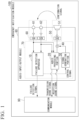
- FIG. 1 is a function block diagram showing an example of an emergency notification module using the failure detection apparatus according to the embodiment of the present invention.
- the emergency notification module 100 is installed in the cabin of a vehicle or the like, and performs emergency notification during an emergency such as the occurrence of an accident.
- the emergency notification module 100 is provided with a communication module 90 and an audio input/output module 80.
- the communication module 90 is provided with a radio transceiver (not shown) and communicates with an emergency center or the like via the radio transceiver.
- the communication module 90 inputs a transmission sound signal such as an emergency notification from the user that is output from the audio input/output module 80, and transmits the transmission sound signal to the emergency center or the like.
- the communication module 90 receives a reception sound signal such as a response to the emergency notification output from an emergency center or the like, and outputs the reception sound signal to the audio input/output module 80.
- the communication module 90 inputs a failure detection signal outputted from the audio input/output module 80 and transmits a failure detection signal to the emergency center or the like.
- the audio input/output module 80 is provided with an audio output device 50, an audio input device 60, and a processor 70.
- the audio output device 50 is provided with a DAC (Digital Analog Converter), an amplifier, and a speaker.
- the audio input device 60 is provided with microphones 61 and 62, an amplifier, and an analog-digital converter (ADC).
- the processor 70 is provided with a failure detection apparatus 10, an audio processing portion 20, a signal generation portion 30, and an adder 40.
- Each of the failure detection apparatus 10, the audio processing portion 20, the signal generation portion 30, and the adder 40 is, for example, a CPU (Central Processing Unit), a DSP (Digital Signal Processor), or a processor that is a combination thereof, and realized by the execution of a program (software) stored in program memory. Some or all of the functions executed by these programs may be realized by an analog control circuit or hardware such as LSI (Large Scale Integration), ASIC (Application Specific Integrated Circuit), FPGA (Field Programmable Gate Array), or may be realized through the collaboration of software and hardware.
- LSI Large Scale Integration
- ASIC Application Specific Integrated Circuit
- FPGA Field Programmable Gate Array
- the failure detection apparatus 10 By outputting a control signal, the failure detection apparatus 10 causes the signal generation portion 30 to generate a confirmation signal having frequencies in a band other than the audible band.
- the confirmation signal is emitted (output) as a sound from the audio output device 50 via the adder 40. Also, the confirmation signal that is output loops around to the audio input device 60 via the space inside the vehicle cabin, and is picked up (input) by the audio input device 60 as an input signal.
- the failure detection apparatus 10 inputs the input signal from the audio input device 60. In addition, the failure detection apparatus 10 detects whether or not the audio output device 50 and the audio input device 60 operate normally, on the basis of the confirmation signal and the input signal.
- the audio processing portion 20 inputs the received sound signal from the communication module 90 and outputs the reception sound signal to the audio output device 50 via the adder 40.
- the audio processing portion 20 inputs an input signal from the audio input device 60, performs audio processing on the input signal, and outputs the input signal after audio processing (transmission sound signal) to the communication module 90.
- the signal generation portion 30 generates a signal having a predetermined frequency according to a control signal from the failure detection apparatus 10.
- the signal generation portion 30 uses, for example, a pulse generator or DTMF (Dual Tone Multi-Frequency) generator to generate a signal having a predetermined frequency.
- DTMF Dual Tone Multi-Frequency
- the signal generation portion 30 generates the signal having a predetermined frequency selected from among eight predetermined frequencies (tone signals) between 697 and 1633 Hz in the DTMF generator, and by performing signal processing using the double-angle formula shown in Equation (1) and the triple-angle formula shown in Equation (2) below on the tone signal, can generate a signal having a predetermined frequency.
- the signal generation portion 30 generates a tone signal of 697 Hz in DTMF, and then can generate a signal having a frequency of 2091 Hz by multiplying the tone signal by 3 based on the above Equation (2).
- the signal generation portion 30 adjusts the signal level of the generated signal having the predetermined frequency, and generates a confirmation signal.
- the adder 40 adds the reception sound signal from the audio processing portion 20 and the confirmation signal from the signal generation portion 30, and outputs the summed signal to the audio output device 50.
- the audio output device 50 converts the digital signal from the adder 40 into an analog signal by the DAC and outputs the converted analog signal to the speaker 51 via a buffer such as an amplifier.
- the speaker 51 converts the electrical signal from the amplifier into physical vibrations and outputs the physical vibrations to the outside.
- the audio input device 60 converts the vibration amplitude of external sound or the sound output from the audio output device 50 into an analog electrical signal by the microphones 61 and 62, converts the converted analog electric signal into a digital signal by the ADC, and outputs the digital signal obtained by the conversion to the failure detection apparatus 10 and the audio processing portion 20.
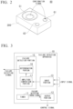
- FIG. 2 is a perspective view showing an example of the audio input/output module 80.
- the speaker 51 is installed at the center of a main surface of a housing 200.
- the microphone 61 is installed at one of the adjacent top portions of the main surface of the housing 200 and the microphone 62 at the other so that the distances from the speaker 51 are equal to each other.
- the confirmation signal output from the speaker 51 can be input to the microphones 61 and 62 at substantially the same sound pressure level.
- the confirmation signal output from the speaker 51 loops around to the microphones 61 and 62 to be input from the microphones 61 and 62.
- the failure detection apparatus 10 causes the signal generation portion 30 to adjust the signal level of the confirmation signal so that the sound pressure at the microphones 61 and 62 when the confirmation signal loops around and is input to the microphones 61 and 62 becomes, for example, 70 dB SPL (Sound Pressure Level) on average.
- this kind of audio input/output module 80 may be mounted at any position on the ceiling between the driver's seat and the passenger seat. In this case, since the confirmation signal outputted from the speaker 51 is emitted toward the space between occupants of the driver's seat and the passenger seat, it can be made less prone to enter the ears of the driver and the passenger.
- the audio processing performed by the audio processing portion 20 includes processing for preventing howling and the like from being included in the input signal. Howling occurs when the sound output from the audio output device 50 loops around to the audio input device 60 and is input from the audio input device 60 together with external sound.
- the microphone 61 and the microphone 62 are installed such that the distances thereto from the speaker 51 are equal to each other. Thereby the sound that is obtained by the sound output from the speaker 51, including the confirmation signal component, looping around and being inputted to the audio input device 60 is equally inputted to the microphone 61 and the microphone 62.
- the audio processing unit 20 by subtracting from one input signal the other input signal with respect to the input signal from the microphone 61 of the audio input device 60 and the input signal from the microphone 62, can remove sound that results from sound outputted from the audio output device 50 including the confirmation signal component looping around to the audio input device 60 and being input, and thereby prevent howling. By preventing the howling from occurring by the audio processing portion 20, it is possible to suppress a decrease in sound quality of the transmission sound signal.
- FIG. 3 is a diagram showing an example of the failure detection apparatus 10.
- the failure detection apparatus 10 is provided with a timer 11, an output portion 12, an input portion 13, and a failure detection portion 15.
- the failure detection apparatus 10 for example receives a failure detection timing signal output from the timer 11 at an arbitrary timing, performs a failure detection process, and outputs the detection result as a failure detection signal.
- the arbitrary timing referred to here may be any timing after startup, and may for example be a timing of a periodic time after startup. In this way, since the failure detection processing can be performed at an arbitrary timing, the failure detection processing can be performed even at times other than startup.
- the output portion 12 causes the signal generation portion to generate a confirmation signal composed of a frequency in a band other than the audible band.
- the audible band is a band of frequencies that a person can perceive as sound due to tympanic membrane vibration or the like, and generally refers to a frequency band of about 20 Hz to 20 kHz.
- the confirmation signal composed of a frequency in a band other than the audible band means a signal composed of frequencies which are generally difficult to be perceived by the human auditory system.
- a signal composed of a frequency in the audible band may be included in a portion of the confirmation signal to the extent of being difficult to be perceived by the human auditory system.
- the frequency of the confirmation signal will be described. While the confirmation signal should be a signal having a frequency higher than about 20 kHz, it is preferably a frequency that can be output from the audio output device 50 and a frequency that can be input from the audio input device 60.
- Output devices such as speakers and input devices such as microphones are devices that generally output and input sound signals in the audible range. For this reason, the signal should be expressible up to about 20 kHz, and the sampling frequency generally processed by these devices is often around 48 kHz, or multiples thereof such as about 96 kHz or about 192 kHz.
- the frequency be such that the linearity not be so high (for example, 100 kHz or less).
- the confirmation signal be a signal without signal distortion.
- a confirmation signal be constituted at a frequency that can be input and output by a general-purpose audio input/output device, loops around adequately, and has low distortion.
- the confirmation signal is composed of a frequency of 16 to 24 kHz.
- FIGS. 4A and 4B are diagrams for explaining the confirmation signal.
- FIG. 4A is a diagram showing an example of a confirmation signal.
- FIG. 4B is an enlarged view of a portion of the confirmation signal.
- the vertical axis represents signal amplitude and the horizontal axis represents time.
- the confirmation signal is, for example, a burst signal.
- the confirmation signal is, for example, a burst signal.
- the length of section A1 is equal to the length of section A2, and the ratio (duty ratio) of the signal section (the section A1, for example 0.5 sec) to the period (section A including section A1 and section A2, for example 1 second) is about 50%.
- the burst period and the duty ratio are arbitrary.
- the duty ratio of the input signal from the audio input device 60 is within the predetermined range, the duty ratio is determined to be normal.
- the predetermined range can be arbitrarily set, the range may be set in consideration of the case of naturally present noise being included in the duty ratio that was set when generating the confirmation signal. By doing this, erroneous determination due to mixing-in of noise can be reduced.
- the envelope of the confirmation signal gradually increases during the section A1, and the envelope of the confirmation signal gradually decreases during the section A2. That is, the confirmation signal is adjusted and output so as to suppress abrupt changes of the envelope. A sudden change in the envelope distorts the signal waveform, which may be a cause of noise due to signal distortion.
- the failure detection apparatus 10 of the present embodiment can suppress the generation of noise in the audible band by signal distortion that occurs from switching between a signal section and a non-signal section, by adjusting the pulse width of the confirmation signal so that the envelope of the burst signal gradually changes.
- a threshold value is set for the signal amplitude.
- the section having an amplitude equal to or greater than the predetermined threshold value is section C.
- an input signal from the audio input device 60 is input to the input portion 13, which outputs the input signal to the failure detection portion 15.
- the confirmation signal that looped around to the audio input device 60 is included in the input signal.
- the input portion 13 may pass the input signal through a bandpass filter and output the signal that has passed through the bandpass filter to the failure detection portion 15.
- the bandpass filter has the property of blocking a signal having a frequency different from the frequency of the confirmation signal.
- the failure detection portion 15 Based on the confirmation signal and the input signal, the failure detection portion 15 detects whether at least one of the audio output device 50 and the audio input device 60 is normal.
- the failure detection portion 15 includes an amplitude comparison portion 17 and a determination portion 16.
- the amplitude comparison portion 17 compares the amplitude of the input signal and a predetermined threshold value. The amplitude comparison portion 17 notifies the comparison result to the determination portion 16.
- the determination portion 16 receives the comparison result from the amplitude comparison portion 17, holds the comparison result for a predetermined time, and finds the ratio of the time with respect to the burst cycle during which the input signal is equal to or greater than the threshold value (the ratio of section C to section A in FIG. 4A , hereinbelow referred to as the section ratio).
- the determination portion 16 determines that the audio output device 50 and the audio input device 60 are normal when the section ratio is within a predetermined range set in advance. When the section ratio is outside the predetermined range set in advance, the determination portion 16 determines that either one of the audio output device 50 and the audio input device 60 is not normal.
- the determination unit 16 outputs the determination result as a failure detection signal.
- the failure detection portion 15 may perform failure detection on an input signal obtained by summing up the signals input from both of the microphones 61 and 62 of the audio input device 60, or may perform failure detection for each of the signals input from the microphones 61 and 62, respectively.
- the failure detection portion 15 can determine that the input signals have been input from both of the microphones 61 and 62.
- the failure detection portion 15 can determine that the input signal from either one of the microphones 61 and 62 has been normally input, while the input signal from the other has not been normally input.
- the failure detection portion 15 When performing individual failure detection, for example the failure detection portion 15 first causes the input portion 13 to input the signal from the microphone 61 and performs failure detection. Next, the failure detection portion 15 causes the input portion 13 to input the signal from the microphone 62 and performs failure detection. By doing so, the failure detection portion 15 can detect whether each of the microphones 61 and 62 is normal or not. For example, when either one of the microphones 61 or 62 is not normal, there is determined to be a minor failure, and when both of the microphones 61 and 62 are not normal, there is determined to be a serious failure. The failure detection portion 15 may output a failure detection signal including information expressing that the failure is a minor failure or a serious failure.
- FIGS. 5A and 5B are diagrams for explaining the relationship between an input signal and noise.
- FIG. 5A is a diagram showing an example of a waveform of noise existing in the environment, with the noise having a frequency close to the frequency constituting the confirmation signal. For example, it is a waveform of noise generated when a metal object such as a metal key holder strikes another metal object.
- FIG. 5B is a diagram showing an example of the waveform of the input signal. Even when using an input signal passed through a bandpass filter in the failure detection processing, noise having a frequency close to the frequency constituting the confirmation signal cannot be removed. For this reason, sometimes noise becomes mixed with the confirmation signal in the input signal.
- FIG. 6 is a diagram for explaining a failure detection signal.
- the vertical axis represents signal level while the horizontal axis represents time.
- the output waveform of the failure detection signal is shown on the upper side of FIG. 6 , while the time at which the failure detection process is performed is shown in the second row of FIG. 6 .
- the example of FIG. 6 shows the case of the failure detection process being periodically performed at the period T.
- the failure detection portion 15 performs failure detection at the period T, and upon determining that the audio output device 50 and the audio input device 60 are both normal, inverts the failure detection signal.
- FIG. 6 shows the case of the failure detection process being periodically performed at the period T.
- the failure detection portion 15 performs failure detection at the period T, and upon determining that the audio output device 50 and the audio input device 60 are both normal, inverts the failure detection signal.
- the failure detection process is performed at each time of the times TS1 to TS3, and it is determined that the audio output device 50 and the audio input device 60 are both normal at each time of the times T1 to T3. Then, at each time of the times T1 to T3, the failure detection signal is inverted from the low level to the high level or from the high level to the low level and outputted.
- the failure detection process is performed at time TS4, but at time T4, since it is determined that at least one of the audio output device 50 or the audio input device 60 is not normal, the failure detection signal is outputted as is at the high level without the failure detection signal (high level) at time T3 being inverted.
- the failure detection signal when the audio input/output module 80 is not operating normally, the failure detection signal is not inverted. That is, inversion (change) of the failure detection signal can indicate that the audio input/output module 80 including at least the failure detection apparatus 10 is operating normally. Further, by causing the failure detection apparatus 10 of the present embodiment to output the failure detection signal as a toggle signal, it is possible to notify the communication module 90 not only whether or not the audio output device 50 and the audio input device 60 are normal, but also whether or not the processor 70 itself is normal.
- the failure detection signal may be output using a plurality of communication paths.
- the communication module 90 may be notified of the failure detection signal through other communication paths, and so a robust configuration can be achieved.
- a plurality of physical signal sources may be used as communication paths.
- the communication path for outputting the failure detection signal from the failure detection apparatus 10, and all or some signal lines for outputting the result of failure detection from the failure detection apparatus 10 to the audio processing portion 20 and outputting the transmission sound signal for notification from the audio processing portion 20 to the communication module 90 may be used as communication paths.
- the communication path used for notification from the audio processing portion 20 to the communication module 90 and the communication path for outputting the failure detection signal from the failure detection apparatus 10 may be used together to output the failure detection result.
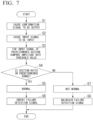
- FIG. 7 is a flowchart showing an example of the failure detection process.
- the failure detection portion 15 when a failure detection timing signal from the timer 11 is input, the failure detection portion 15 outputs a control signal to the signal generation unit 30 to cause a confirmation signal to be output (Step S1).
- the confirmation signal is output from the audio output device 50 via the adder 40, loops around to the microphones 61 and 62, and is input from the audio input device 60.
- the failure detection portion 15 inputs the input signal from the audio input device 60 (Step S2).
- the failure detection portion 15 identifies a section on the basis of the burst period of the confirmation signal and, for the input signal in that predetermined section, compares the amplitude of the input signal and a predetermined threshold value (Step S3).
- the failure detection portion 15 finds, in the predetermined section that has been identified, the ratio of a section having an amplitude equal to or greater than the predetermined threshold value to the predetermined section (section ratio), and determines whether the section ratio is within a predetermined range (Step S4). If the section ratio is within the predetermined range, the failure detection portion 15 determines that the audio output device 50 and the audio input device 60 are normal (Step S5).
- the failure detection portion 15 Upon making a determination to the effect of being normal, the failure detection portion 15 inverts the signal level of the failure detection signal (Step S6). On the other hand, if the section ratio is outside the predetermined range, the failure detection portion 15 determines that at least either one of the audio output device 50 and the audio input device 60 is not normal (Step S7). Upon making a determination to the effect of not being normal, the failure detection portion 15 does not invert the signal level of the failure detection signal. By doing so, the failure detection signal becomes a high-level or low-level signal (Step S8).
- the failure detection apparatus 10 of the present embodiment is provided with the output portion 12 that causes the confirmation signal configured with a frequency in a band other than the audible band to be output from the audio output device 50, the input portion 13 that receives the input signal from the audio input device 60, and the failure detection portion 15 that detects whether or not both of the audio output device 50 and the audio input device 60 are normal based on the confirmation signal and the input signal, whereby the failure detection apparatus 10 can perform failure detection without emitting a sound having a frequency in the audible band during failure detection.
- the failure detection apparatus 10 of the present embodiment is not limited to the constitutions described above, and in order to more accurately perform failure detection, for example, the frequency composing the confirmation signal may be configured to be changeable.
- the frequency of the confirmation signal should at least be configured outside the audible band.
- the failure detection apparatus 10 may output the confirmation signal so as to change the frequency thereof with the passage of time such that the frequency of the confirmation signal is output in the order of 19 kHz, 20 kHz, and 21 kHz for specific sections.
- failure detection is performed via three types of bandpass filters that cut off frequencies other than each frequency.
- the failure detecting portion 15 determines whether or not a signal is detected in which the section ratio of the input signal passed through a 19 kHz - bandpass filter is within the predetermined range, and whether or not a signal is detected in which the section ratio of the input signal passed through 20 kHz and 21 kHz bandpass filters is not within the predetermined range.
- the failure detection portion 15 determines whether or not a signal is detected in which the section ratio of the input signal passed through a 20 kHz bandpass filter is within the predetermined range, and whether or not a signal is detected in which the section ratio of the input signal passed through 19 kHz and 21 kHz bandpass filters is not within the predetermined range. Moreover, the failure detection portion 15 determines whether or not a signal is detected in which the section ratio of the input signal passed through a 21 kHz bandpass filter is within the predetermined range, and whether or not a signal is detected in which the section ratio of the input signal passed through 19 kHz and 20 kHz bandpass filters is not within the predetermined range.
- the failure detection portion 15 may make a determination of normality. In this way, it is possible to perform failure detection more accurately by changing the frequency of the confirmation signal.
- the output level of the confirmation signal is kept constant, but is not limited thereto.
- a pattern may be repeated such that the output level of the confirmation signal is made to be output at the three levels of high, middle and low.
- the failure detecting portion 15 compares the input signal with a plurality of threshold values (in this case, assume the three threshold values of threshold value 1, threshold value 2 smaller than threshold value 1, threshold value 3 smaller than threshold value 2).
- the failure detection portion 15 confirms the detection of a signal in which the section ratio of a signal greater than the threshold value 1 is within the predetermined range.
- the failure detection portion 15 confirms the detection of a signal in which the section ratio of a signal greater than the threshold value 1 is not within the predetermined range, and the detection of a signal in which the section ratio of a signal greater than the threshold value 2 is within the predetermined range.
- the failure detection portion 15 confirms the detection of a signal in which the section ratio of a signal greater than the threshold value 2 is not within the predetermined range, and the detection of a signal in which the section ratio of a signal greater than the threshold value 3 is within the predetermined range.
- the failure detection portion 15 makes a determination of normality.
- the failure detection portion may also detect a frequency or the like included in the noise before performing failure detection. Failure detection can be performed more accurately by detecting the state of noise before performing failure detection. For example, when the same frequency as the frequency of the confirmation signal used for failure detection is included in the noise at a certain level or higher, failure detection is not performed until there is a decrease in the level of the frequency included in the noise that is the same as the frequency of the confirmation signal used for failure detection, or the frequency of the confirmation signal is changed so that the frequency included in the noise does not overlap with the frequency of the confirmation signal.
- the embodiment described above can be applied in an audio input/output module, an emergency notification module, and a failure detection method.
Landscapes
- Physics & Mathematics (AREA)
- Engineering & Computer Science (AREA)
- Acoustics & Sound (AREA)
- Signal Processing (AREA)
- Health & Medical Sciences (AREA)
- Otolaryngology (AREA)
- General Physics & Mathematics (AREA)
- General Health & Medical Sciences (AREA)
- Computer Security & Cryptography (AREA)
- Business, Economics & Management (AREA)
- Emergency Management (AREA)
- Circuit For Audible Band Transducer (AREA)
- Emergency Alarm Devices (AREA)
- Telephone Function (AREA)
Claims (9)
- Ein-/Ausgabemodul (80), umfassend:eine Audioeingabevorrichtung (60);eine Audioausgabevorrichtung (50), die in einem Abstand von der Audioeingabevorrichtung (60) angeordnet ist; undeine Fehlererkennungseinrichtung (10), umfassend:
einen Ausgabeabschnitt (12), der an die Audioausgabevorrichtung (50) ein Bestätigungssignal ausgibt, das ein Burstsignal ist und in einem anderen Frequenzband als einem hörbaren Band ist, wobei das Bestätigungssignal:während einer Zeitdauer (A) des Burstsignals, das einen ersten Teil (A1) und einen zweiten Teil (A2) einschließt, von dem ersten Teil (A1) in den zweiten Teil (A2) umschaltet,eine Hüllkurve einschließt, die im Zeitverlauf während des ersten Teils (A1) schrittweise zunimmt und im Zeitverlauf während des zweite Teils (A2) schrittweise abnimmt, undein willkürliches Einschaltverhältnis des ersten Teils (A1) der Zeitdauer (A) aufweist;einen Eingabeabschnitt (13), der ein Eingabesignal von der Audioeingabevorrichtung (60) empfängt; undeinen Fehlererkennungsabschnitt (15), der erkennt, ob die Audioausgabevorrichtung (50) und die Audioeingabevorrichtung (60) normal arbeiten,dadurch gekennzeichnet, dass der Fehlererkennungsabschnitt (15) basierend auf einem Verhältnis einer Zeitlänge eines dritten Teils (C) des Burstsignals und einer gesamten Zeitlänge der Zeitdauer (A) des Burstsignals erkennt, ob die Audioausgabevorrichtung (50) und die Audioeingabevorrichtung (60) normal arbeiten,wobei der dritte Teil (C) den ersten Teil (A1) und einen Abschnitt des zweiten Teils (A2), in dem eine Amplitude davon gleich groß oder größer ist als ein vorbestimmter Schwellenwert, einschließt. - Ein-/Ausgabemodul nach Anspruch 1, wobei das Bestätigungssignal eine Frequenz einschließt, die gleich groß oder größer ist als 16 kHz und gleich groß oder kleiner ist als 24 kHz.
- Ein-/Ausgabemodul (80) nach Anspruch 1, wobei das Fehlererkennungsabschnitt (15) auf der Grundlage des Eingabesignals, nachdem es durch einen Bandpassfilter durchgeführt wurde, erkennt, ob die Audioausgabevorrichtung (12) und die Audioeingabevorrichtung (13) normal arbeiten.
- Audioein-/-ausgabemodul (80) nach Anspruch 1, wobei das von der Fehlererkennungseinrichtung (10) ausgegebene Fehlererkennungssignal ein Signal ist, das hin- und herschaltet, wenn kein Fehler erkannt wurde.
- Audioein-/-ausgabemodul (80) nach Anspruch 1, wobei das von der Fehlererkennungseinrichtung (10) ausgegebene Fehlererkennungssignal von einer Vielzahl von Kommunikationswegen ausgegeben wird.
- Audioein-/-ausgabemodul (80) nach Anspruch 1, wobei eine Vielzahl von Audioeingabevorrichtungen (61, 62) vorhanden ist.
- Audioein-/-ausgabemodul (80) nach Anspruch 6, wobei die Fehlererkennungseinrichtung (10) erkennt, ob in jeder der Vielzahl von Audioeingabevorrichtungen (61, 62) ein Fehler vorliegt oder nicht.
- Notfallmeldemodul (100), umfassend:das Audioein-/-ausgabemodul (80) nach einem der Ansprüche 1 bis 7; undein Kommunikationsmodul (90), das das von der Audioeingabevorrichtung (60) eingegebenen Eingabesignals nach außerhalb ausgibt, und ein Empfangstonsignal, das von außerhalb von der Audioausgabevorrichtung (50) empfangen wurde, abgibt.
- Fehlererkennungsverfahren für ein Audioein-/-ausgabemodul (80), einschließend eine Audioeingabevorrichtung (60) und eine Audioausgabevorrichtung (50), die in einem Abstand von der Audioeingabevorrichtung angeordnet ist, wobei das Verfahren Folgendes umfasst:Ausgeben von der Audioausgabevorrichtung (50) eines Bestätigungssignals, das ein Burstsignal ist und in einem anderen Frequenzband als dem hörbaren Band ist, wobei das Bestätigungssignal:während einer Zeitdauer (A) des Burstsignals, das einen ersten Teil (A1) und einen zweiten Teil (A2) einschließt, von dem ersten Teil (A1) in den zweiten Teil(A2) umschaltet;eine Hüllkurve einschließt, die im Zeitverlauf während des ersten Teils (A1) schrittweise zunimmt und im Zeitverlauf während des zweite Teils (A2) schrittweise abnimmt, undein willkürliches Einschaltverhältnis des ersten Teils (A1) der Zeitdauer (A) aufweist;Eingeben eines Eingabesignals von der Audioeingabevorrichtung (60); undErkennen, ob die Audioausgabevorrichtung (50) und die Audioeingabevorrichtung (60) normal arbeiten,dadurch gekennzeichnet, dass der Schritt des Erkennens, ob die Audioausgabevorrichtung (50) und die Audioeingabevorrichtung (60) normal arbeiten, basierend auf einem Verhältnis einer Zeitlänge eines dritten Teils (C) des Burstsignals und einer gesamten Zeitlänge der Zeitdauer (A) des Burstsignals ausgeführt wird,wobei der dritte Teil (C) den ersten Teil (A1) und einen Abschnitt des zweiten Teils (A2), in dem eine Amplitude davon gleich groß oder größer ist als ein vorbestimmter Schwellenwert, einschließt.
Applications Claiming Priority (1)
| Application Number | Priority Date | Filing Date | Title |
|---|---|---|---|
| PCT/JP2016/080602 WO2018070046A1 (ja) | 2016-10-14 | 2016-10-14 | 故障検出装置、音声入出力モジュール、緊急通報モジュール及び故障検出方法 |
Publications (3)
| Publication Number | Publication Date |
|---|---|
| EP3402219A1 EP3402219A1 (de) | 2018-11-14 |
| EP3402219A4 EP3402219A4 (de) | 2019-12-04 |
| EP3402219B1 true EP3402219B1 (de) | 2023-05-03 |
Family
ID=61905428
Family Applications (1)
| Application Number | Title | Priority Date | Filing Date |
|---|---|---|---|
| EP16918986.7A Active EP3402219B1 (de) | 2016-10-14 | 2016-10-14 | Audioein-/-ausgabemodul, notfallmeldemodul und fehlererkennungsverfahren |
Country Status (5)
| Country | Link |
|---|---|
| US (1) | US10659895B2 (de) |
| EP (1) | EP3402219B1 (de) |
| JP (1) | JP6428976B2 (de) |
| CN (1) | CN108605190B (de) |
| WO (1) | WO2018070046A1 (de) |
Families Citing this family (12)
| Publication number | Priority date | Publication date | Assignee | Title |
|---|---|---|---|---|
| CN109168120B (zh) * | 2018-11-16 | 2021-04-06 | 深圳市爱培科技术股份有限公司 | 一种扬声器和麦克风测试方法、智能终端及存储介质 |
| JP7189033B2 (ja) * | 2019-01-23 | 2022-12-13 | ラピスセミコンダクタ株式会社 | 半導体装置及び音出力装置 |
| JP7254593B2 (ja) * | 2019-04-01 | 2023-04-10 | ニッタン株式会社 | 非常放送装置 |
| JP7228497B2 (ja) * | 2019-09-27 | 2023-02-24 | 三菱重工業株式会社 | 信号処理装置、信号処理方法およびプログラム |
| CN111025968B (zh) * | 2019-12-05 | 2022-09-27 | 深圳震有科技股份有限公司 | Dsp收号故障检测处理方法及装置、计算机设备、介质 |
| US11166118B1 (en) * | 2020-04-23 | 2021-11-02 | Dell Products L.P. | Mobile aware intermodal assistant |
| JP7442390B2 (ja) * | 2020-06-01 | 2024-03-04 | 株式会社日立ビルシステム | 軸受検査装置及び軸受検査方法 |
| WO2021258037A1 (en) * | 2020-06-19 | 2021-12-23 | Dolby Laboratories Licensing Corporation | Non-intrusive transducer health detection |
| US11297452B2 (en) * | 2020-08-14 | 2022-04-05 | Subaru Corporation | Inspection system and inspection method |
| EP4084503A1 (de) | 2021-04-28 | 2022-11-02 | Nxp B.V. | Fehlererkennungsverfahren und -vorrichtung für audiowiedergabesysteme |
| US12066499B2 (en) | 2021-09-28 | 2024-08-20 | Carrier Corporation | Piezo sounder self-test using feedback pin |
| JP7856032B2 (ja) * | 2023-03-23 | 2026-05-11 | トヨタ自動車株式会社 | 通信装置 |
Citations (5)
| Publication number | Priority date | Publication date | Assignee | Title |
|---|---|---|---|---|
| US20070030978A1 (en) * | 2005-08-03 | 2007-02-08 | Sony Corporation | Apparatus and method for measuring sound field |
| US7382243B1 (en) * | 2005-01-14 | 2008-06-03 | Isaac Shepher | Personal emergency response system with interconnected slave units |
| JP2008301079A (ja) * | 2007-05-30 | 2008-12-11 | Pioneer Electronic Corp | 音響装置、遅延時間測定方法、遅延時間測定プログラム及びその記憶媒体 |
| US20100019781A1 (en) * | 2008-04-28 | 2010-01-28 | Genaro Woelfl | Electrical load detection apparatus |
| US20150296292A1 (en) * | 2014-04-14 | 2015-10-15 | Apple Inc. | Multi-channel audio system having a shared current sense element for estimating individual speaker impedances |
Family Cites Families (16)
| Publication number | Priority date | Publication date | Assignee | Title |
|---|---|---|---|---|
| US4037222A (en) * | 1975-10-02 | 1977-07-19 | Gulf & Western Manufacturing Company (Systems) | Supervision of transducers |
| JP3023424B2 (ja) * | 1992-05-19 | 2000-03-21 | ティーオーエー株式会社 | 異常監視装置付き拡声装置 |
| JP3775233B2 (ja) | 2001-03-26 | 2006-05-17 | 株式会社デンソー | 車両緊急情報通報装置および異常診断方法 |
| FR2903853B1 (fr) * | 2006-07-13 | 2008-10-17 | Regie Autonome Transports | Procede et dispositif de diagnostic de l'etat de fonctionnement d'un systeme de sonorisation |
| US20120286946A1 (en) * | 2011-05-15 | 2012-11-15 | Karl Thomas F | Fully supervised self testing alarm notification apparatus |
| US9565504B2 (en) * | 2012-06-19 | 2017-02-07 | Toa Corporation | Speaker device |
| JP6050643B2 (ja) * | 2012-09-24 | 2016-12-21 | アルインコ株式会社 | 断線検知回路及び方法、無線送受信装置並びに電子機器 |
| CN104168532A (zh) | 2013-05-15 | 2014-11-26 | 光宝光电(常州)有限公司 | 扬声器异音检测方法及装置 |
| US9007201B2 (en) * | 2013-05-17 | 2015-04-14 | Tyco Fire & Security Gmbh | Method for self-testing notification appliances in alarm systems |
| CN204667145U (zh) * | 2014-06-02 | 2015-09-23 | 罗斯蒙特公司 | 在监视声学噪声时使用的无线现场设备、用于监视工业过程中的噪声的系统、无线现场设备 |
| JP6210458B2 (ja) | 2014-07-30 | 2017-10-11 | パナソニックIpマネジメント株式会社 | 故障検知システム及び故障検知方法 |
| JP6443283B2 (ja) | 2014-12-04 | 2018-12-26 | 株式会社デンソー | 緊急通報装置 |
| WO2016088323A1 (ja) * | 2014-12-04 | 2016-06-09 | 株式会社デンソー | 緊急通報装置 |
| US9454893B1 (en) * | 2015-05-20 | 2016-09-27 | Google Inc. | Systems and methods for coordinating and administering self tests of smart home devices having audible outputs |
| JP6620675B2 (ja) | 2016-05-27 | 2019-12-18 | パナソニックIpマネジメント株式会社 | 音声処理システム、音声処理装置及び音声処理方法 |
| US10365642B2 (en) * | 2016-10-03 | 2019-07-30 | Avaya Inc. | Probe of alarm functionality using communication devices |
-
2016
- 2016-10-14 EP EP16918986.7A patent/EP3402219B1/de active Active
- 2016-10-14 WO PCT/JP2016/080602 patent/WO2018070046A1/ja not_active Ceased
- 2016-10-14 CN CN201680081030.7A patent/CN108605190B/zh active Active
- 2016-10-14 JP JP2018534981A patent/JP6428976B2/ja active Active
-
2018
- 2018-08-07 US US16/057,107 patent/US10659895B2/en active Active
Patent Citations (5)
| Publication number | Priority date | Publication date | Assignee | Title |
|---|---|---|---|---|
| US7382243B1 (en) * | 2005-01-14 | 2008-06-03 | Isaac Shepher | Personal emergency response system with interconnected slave units |
| US20070030978A1 (en) * | 2005-08-03 | 2007-02-08 | Sony Corporation | Apparatus and method for measuring sound field |
| JP2008301079A (ja) * | 2007-05-30 | 2008-12-11 | Pioneer Electronic Corp | 音響装置、遅延時間測定方法、遅延時間測定プログラム及びその記憶媒体 |
| US20100019781A1 (en) * | 2008-04-28 | 2010-01-28 | Genaro Woelfl | Electrical load detection apparatus |
| US20150296292A1 (en) * | 2014-04-14 | 2015-10-15 | Apple Inc. | Multi-channel audio system having a shared current sense element for estimating individual speaker impedances |
Non-Patent Citations (1)
| Title |
|---|
| BOB METZLER: "Audio Measurement Handbook", 16 August 1993 (1993-08-16), XP055117749, Retrieved from the Internet <URL:http://ap.com/download/file/24> [retrieved on 20140513] * |
Also Published As
| Publication number | Publication date |
|---|---|
| EP3402219A4 (de) | 2019-12-04 |
| JPWO2018070046A1 (ja) | 2018-11-29 |
| JP6428976B2 (ja) | 2018-11-28 |
| US10659895B2 (en) | 2020-05-19 |
| CN108605190A (zh) | 2018-09-28 |
| WO2018070046A1 (ja) | 2018-04-19 |
| CN108605190B (zh) | 2020-06-30 |
| EP3402219A1 (de) | 2018-11-14 |
| US20180343531A1 (en) | 2018-11-29 |
Similar Documents
| Publication | Publication Date | Title |
|---|---|---|
| US10659895B2 (en) | Failure detection apparatus, audio input/output module, emergency notification module, and failure detection method | |
| EP1785007B1 (de) | Niederfrequente phasenanpassung für mikrophone | |
| EP3481085A1 (de) | Rückkopplungsdetektor und hörgerät mit einem rückkopplungsdetektor | |
| EP2863656B1 (de) | Lautsprechervorrichtung | |
| US20110249847A1 (en) | Methods and apparatus for early audio feedback cancellation for hearing assistance devices | |
| US20150296297A1 (en) | Anc active noise control audio headset with reduction of the electrical hiss | |
| CN103797816B (zh) | 语音增强系统和方法 | |
| KR20150008471A (ko) | 적응형 잡음 제거(anc)를 갖는 개인용 오디오 디바이스들에서 주파수 및 방향 의존 주변의 사운드 조절 | |
| WO2012170128A1 (en) | Generating a masking signal on an electronic device | |
| CN112866890B (zh) | 一种入耳检测方法及系统 | |
| US10182283B2 (en) | Noise cancellation device and noise cancellation method | |
| CN106254998B (zh) | 包括用于掩蔽耳鸣的信号发生器的听力装置 | |
| US10134264B2 (en) | Emergency report apparatus | |
| EP3419313A1 (de) | Hörgerät mit adaptiver rückkopplungspfadschätzung | |
| EP4047956B1 (de) | Hörgerät mit einem offenschleifigen verstärkungsschätzer | |
| US10313778B2 (en) | Method for operating an electroacoustic system and electroacoustic system | |
| US10388299B2 (en) | Howling suppression device | |
| CN111356069A (zh) | 带有自身语音检测的听力装置及相关方法 | |
| US8760271B2 (en) | Methods and systems to support auditory signal detection | |
| AU2006200957B2 (en) | Hearing device and method for wind noise supression | |
| JP6806123B2 (ja) | 故障検出装置、音声入出力モジュール、及び故障検出方法 | |
| EP3634014A1 (de) | Audioverarbeitungssystem | |
| RU2771296C2 (ru) | Устройство обработки звука | |
| EP4335118B1 (de) | System und verfahren zur hörhilfe | |
| US12418753B2 (en) | Audio device with ultrasound movement detection |
Legal Events
| Date | Code | Title | Description |
|---|---|---|---|
| STAA | Information on the status of an ep patent application or granted ep patent |
Free format text: STATUS: THE INTERNATIONAL PUBLICATION HAS BEEN MADE |
|
| PUAI | Public reference made under article 153(3) epc to a published international application that has entered the european phase |
Free format text: ORIGINAL CODE: 0009012 |
|
| STAA | Information on the status of an ep patent application or granted ep patent |
Free format text: STATUS: REQUEST FOR EXAMINATION WAS MADE |
|
| 17P | Request for examination filed |
Effective date: 20180808 |
|
| AK | Designated contracting states |
Kind code of ref document: A1 Designated state(s): AL AT BE BG CH CY CZ DE DK EE ES FI FR GB GR HR HU IE IS IT LI LT LU LV MC MK MT NL NO PL PT RO RS SE SI SK SM TR |
|
| AX | Request for extension of the european patent |
Extension state: BA ME |
|
| A4 | Supplementary search report drawn up and despatched |
Effective date: 20191105 |
|
| RIC1 | Information provided on ipc code assigned before grant |
Ipc: H04R 29/00 20060101AFI20191028BHEP Ipc: G08B 29/04 20060101ALI20191028BHEP Ipc: H04R 27/00 20060101ALI20191028BHEP Ipc: G08B 29/12 20060101ALI20191028BHEP Ipc: G08B 25/08 20060101ALI20191028BHEP Ipc: G08B 29/10 20060101ALI20191028BHEP |
|
| DAV | Request for validation of the european patent (deleted) | ||
| DAX | Request for extension of the european patent (deleted) | ||
| STAA | Information on the status of an ep patent application or granted ep patent |
Free format text: STATUS: EXAMINATION IS IN PROGRESS |
|
| 17Q | First examination report despatched |
Effective date: 20211015 |
|
| GRAP | Despatch of communication of intention to grant a patent |
Free format text: ORIGINAL CODE: EPIDOSNIGR1 |
|
| STAA | Information on the status of an ep patent application or granted ep patent |
Free format text: STATUS: GRANT OF PATENT IS INTENDED |
|
| INTG | Intention to grant announced |
Effective date: 20221208 |
|
| GRAS | Grant fee paid |
Free format text: ORIGINAL CODE: EPIDOSNIGR3 |
|
| GRAA | (expected) grant |
Free format text: ORIGINAL CODE: 0009210 |
|
| STAA | Information on the status of an ep patent application or granted ep patent |
Free format text: STATUS: THE PATENT HAS BEEN GRANTED |
|
| AK | Designated contracting states |
Kind code of ref document: B1 Designated state(s): AL AT BE BG CH CY CZ DE DK EE ES FI FR GB GR HR HU IE IS IT LI LT LU LV MC MK MT NL NO PL PT RO RS SE SI SK SM TR |
|
| REG | Reference to a national code |
Ref country code: GB Ref legal event code: FG4D |
|
| REG | Reference to a national code |
Ref country code: DE Ref legal event code: R096 Ref document number: 602016079257 Country of ref document: DE |
|
| REG | Reference to a national code |
Ref country code: AT Ref legal event code: REF Ref document number: 1565692 Country of ref document: AT Kind code of ref document: T Effective date: 20230515 Ref country code: CH Ref legal event code: EP |
|
| REG | Reference to a national code |
Ref country code: IE Ref legal event code: FG4D |
|
| REG | Reference to a national code |
Ref country code: LT Ref legal event code: MG9D |
|
| REG | Reference to a national code |
Ref country code: NL Ref legal event code: MP Effective date: 20230503 |
|
| REG | Reference to a national code |
Ref country code: AT Ref legal event code: MK05 Ref document number: 1565692 Country of ref document: AT Kind code of ref document: T Effective date: 20230503 |
|
| PG25 | Lapsed in a contracting state [announced via postgrant information from national office to epo] |
Ref country code: SE Free format text: LAPSE BECAUSE OF FAILURE TO SUBMIT A TRANSLATION OF THE DESCRIPTION OR TO PAY THE FEE WITHIN THE PRESCRIBED TIME-LIMIT Effective date: 20230503 Ref country code: PT Free format text: LAPSE BECAUSE OF FAILURE TO SUBMIT A TRANSLATION OF THE DESCRIPTION OR TO PAY THE FEE WITHIN THE PRESCRIBED TIME-LIMIT Effective date: 20230904 Ref country code: NO Free format text: LAPSE BECAUSE OF FAILURE TO SUBMIT A TRANSLATION OF THE DESCRIPTION OR TO PAY THE FEE WITHIN THE PRESCRIBED TIME-LIMIT Effective date: 20230803 Ref country code: NL Free format text: LAPSE BECAUSE OF FAILURE TO SUBMIT A TRANSLATION OF THE DESCRIPTION OR TO PAY THE FEE WITHIN THE PRESCRIBED TIME-LIMIT Effective date: 20230503 Ref country code: ES Free format text: LAPSE BECAUSE OF FAILURE TO SUBMIT A TRANSLATION OF THE DESCRIPTION OR TO PAY THE FEE WITHIN THE PRESCRIBED TIME-LIMIT Effective date: 20230503 Ref country code: AT Free format text: LAPSE BECAUSE OF FAILURE TO SUBMIT A TRANSLATION OF THE DESCRIPTION OR TO PAY THE FEE WITHIN THE PRESCRIBED TIME-LIMIT Effective date: 20230503 |
|
| PG25 | Lapsed in a contracting state [announced via postgrant information from national office to epo] |
Ref country code: RS Free format text: LAPSE BECAUSE OF FAILURE TO SUBMIT A TRANSLATION OF THE DESCRIPTION OR TO PAY THE FEE WITHIN THE PRESCRIBED TIME-LIMIT Effective date: 20230503 Ref country code: PL Free format text: LAPSE BECAUSE OF FAILURE TO SUBMIT A TRANSLATION OF THE DESCRIPTION OR TO PAY THE FEE WITHIN THE PRESCRIBED TIME-LIMIT Effective date: 20230503 Ref country code: LV Free format text: LAPSE BECAUSE OF FAILURE TO SUBMIT A TRANSLATION OF THE DESCRIPTION OR TO PAY THE FEE WITHIN THE PRESCRIBED TIME-LIMIT Effective date: 20230503 Ref country code: LT Free format text: LAPSE BECAUSE OF FAILURE TO SUBMIT A TRANSLATION OF THE DESCRIPTION OR TO PAY THE FEE WITHIN THE PRESCRIBED TIME-LIMIT Effective date: 20230503 Ref country code: IS Free format text: LAPSE BECAUSE OF FAILURE TO SUBMIT A TRANSLATION OF THE DESCRIPTION OR TO PAY THE FEE WITHIN THE PRESCRIBED TIME-LIMIT Effective date: 20230903 Ref country code: HR Free format text: LAPSE BECAUSE OF FAILURE TO SUBMIT A TRANSLATION OF THE DESCRIPTION OR TO PAY THE FEE WITHIN THE PRESCRIBED TIME-LIMIT Effective date: 20230503 Ref country code: GR Free format text: LAPSE BECAUSE OF FAILURE TO SUBMIT A TRANSLATION OF THE DESCRIPTION OR TO PAY THE FEE WITHIN THE PRESCRIBED TIME-LIMIT Effective date: 20230804 |
|
| PG25 | Lapsed in a contracting state [announced via postgrant information from national office to epo] |
Ref country code: FI Free format text: LAPSE BECAUSE OF FAILURE TO SUBMIT A TRANSLATION OF THE DESCRIPTION OR TO PAY THE FEE WITHIN THE PRESCRIBED TIME-LIMIT Effective date: 20230503 |
|
| PG25 | Lapsed in a contracting state [announced via postgrant information from national office to epo] |
Ref country code: SK Free format text: LAPSE BECAUSE OF FAILURE TO SUBMIT A TRANSLATION OF THE DESCRIPTION OR TO PAY THE FEE WITHIN THE PRESCRIBED TIME-LIMIT Effective date: 20230503 |
|
| PG25 | Lapsed in a contracting state [announced via postgrant information from national office to epo] |
Ref country code: SM Free format text: LAPSE BECAUSE OF FAILURE TO SUBMIT A TRANSLATION OF THE DESCRIPTION OR TO PAY THE FEE WITHIN THE PRESCRIBED TIME-LIMIT Effective date: 20230503 Ref country code: SK Free format text: LAPSE BECAUSE OF FAILURE TO SUBMIT A TRANSLATION OF THE DESCRIPTION OR TO PAY THE FEE WITHIN THE PRESCRIBED TIME-LIMIT Effective date: 20230503 Ref country code: RO Free format text: LAPSE BECAUSE OF FAILURE TO SUBMIT A TRANSLATION OF THE DESCRIPTION OR TO PAY THE FEE WITHIN THE PRESCRIBED TIME-LIMIT Effective date: 20230503 Ref country code: EE Free format text: LAPSE BECAUSE OF FAILURE TO SUBMIT A TRANSLATION OF THE DESCRIPTION OR TO PAY THE FEE WITHIN THE PRESCRIBED TIME-LIMIT Effective date: 20230503 Ref country code: DK Free format text: LAPSE BECAUSE OF FAILURE TO SUBMIT A TRANSLATION OF THE DESCRIPTION OR TO PAY THE FEE WITHIN THE PRESCRIBED TIME-LIMIT Effective date: 20230503 Ref country code: CZ Free format text: LAPSE BECAUSE OF FAILURE TO SUBMIT A TRANSLATION OF THE DESCRIPTION OR TO PAY THE FEE WITHIN THE PRESCRIBED TIME-LIMIT Effective date: 20230503 |
|
| REG | Reference to a national code |
Ref country code: DE Ref legal event code: R097 Ref document number: 602016079257 Country of ref document: DE |
|
| PLBE | No opposition filed within time limit |
Free format text: ORIGINAL CODE: 0009261 |
|
| STAA | Information on the status of an ep patent application or granted ep patent |
Free format text: STATUS: NO OPPOSITION FILED WITHIN TIME LIMIT |
|
| 26N | No opposition filed |
Effective date: 20240206 |
|
| PG25 | Lapsed in a contracting state [announced via postgrant information from national office to epo] |
Ref country code: SI Free format text: LAPSE BECAUSE OF FAILURE TO SUBMIT A TRANSLATION OF THE DESCRIPTION OR TO PAY THE FEE WITHIN THE PRESCRIBED TIME-LIMIT Effective date: 20230503 |
|
| PG25 | Lapsed in a contracting state [announced via postgrant information from national office to epo] |
Ref country code: SI Free format text: LAPSE BECAUSE OF FAILURE TO SUBMIT A TRANSLATION OF THE DESCRIPTION OR TO PAY THE FEE WITHIN THE PRESCRIBED TIME-LIMIT Effective date: 20230503 Ref country code: IT Free format text: LAPSE BECAUSE OF FAILURE TO SUBMIT A TRANSLATION OF THE DESCRIPTION OR TO PAY THE FEE WITHIN THE PRESCRIBED TIME-LIMIT Effective date: 20230503 Ref country code: MC Free format text: LAPSE BECAUSE OF FAILURE TO SUBMIT A TRANSLATION OF THE DESCRIPTION OR TO PAY THE FEE WITHIN THE PRESCRIBED TIME-LIMIT Effective date: 20230503 |
|
| REG | Reference to a national code |
Ref country code: CH Ref legal event code: PL |
|
| REG | Reference to a national code |
Ref country code: BE Ref legal event code: MM Effective date: 20231031 |
|
| PG25 | Lapsed in a contracting state [announced via postgrant information from national office to epo] |
Ref country code: LU Free format text: LAPSE BECAUSE OF NON-PAYMENT OF DUE FEES Effective date: 20231014 |
|
| PG25 | Lapsed in a contracting state [announced via postgrant information from national office to epo] |
Ref country code: LU Free format text: LAPSE BECAUSE OF NON-PAYMENT OF DUE FEES Effective date: 20231014 |
|
| PG25 | Lapsed in a contracting state [announced via postgrant information from national office to epo] |
Ref country code: CH Free format text: LAPSE BECAUSE OF NON-PAYMENT OF DUE FEES Effective date: 20231031 |
|
| PG25 | Lapsed in a contracting state [announced via postgrant information from national office to epo] |
Ref country code: CH Free format text: LAPSE BECAUSE OF NON-PAYMENT OF DUE FEES Effective date: 20231031 |
|
| PG25 | Lapsed in a contracting state [announced via postgrant information from national office to epo] |
Ref country code: BE Free format text: LAPSE BECAUSE OF NON-PAYMENT OF DUE FEES Effective date: 20231031 |
|
| PG25 | Lapsed in a contracting state [announced via postgrant information from national office to epo] |
Ref country code: IE Free format text: LAPSE BECAUSE OF NON-PAYMENT OF DUE FEES Effective date: 20231014 |
|
| PG25 | Lapsed in a contracting state [announced via postgrant information from national office to epo] |
Ref country code: IE Free format text: LAPSE BECAUSE OF NON-PAYMENT OF DUE FEES Effective date: 20231014 |
|
| PG25 | Lapsed in a contracting state [announced via postgrant information from national office to epo] |
Ref country code: BG Free format text: LAPSE BECAUSE OF FAILURE TO SUBMIT A TRANSLATION OF THE DESCRIPTION OR TO PAY THE FEE WITHIN THE PRESCRIBED TIME-LIMIT Effective date: 20230503 |
|
| PG25 | Lapsed in a contracting state [announced via postgrant information from national office to epo] |
Ref country code: BG Free format text: LAPSE BECAUSE OF FAILURE TO SUBMIT A TRANSLATION OF THE DESCRIPTION OR TO PAY THE FEE WITHIN THE PRESCRIBED TIME-LIMIT Effective date: 20230503 |
|
| PG25 | Lapsed in a contracting state [announced via postgrant information from national office to epo] |
Ref country code: CY Free format text: LAPSE BECAUSE OF FAILURE TO SUBMIT A TRANSLATION OF THE DESCRIPTION OR TO PAY THE FEE WITHIN THE PRESCRIBED TIME-LIMIT; INVALID AB INITIO Effective date: 20161014 |
|
| PG25 | Lapsed in a contracting state [announced via postgrant information from national office to epo] |
Ref country code: HU Free format text: LAPSE BECAUSE OF FAILURE TO SUBMIT A TRANSLATION OF THE DESCRIPTION OR TO PAY THE FEE WITHIN THE PRESCRIBED TIME-LIMIT; INVALID AB INITIO Effective date: 20161014 |
|
| PG25 | Lapsed in a contracting state [announced via postgrant information from national office to epo] |
Ref country code: TR Free format text: LAPSE BECAUSE OF FAILURE TO SUBMIT A TRANSLATION OF THE DESCRIPTION OR TO PAY THE FEE WITHIN THE PRESCRIBED TIME-LIMIT Effective date: 20230503 |
|
| PGFP | Annual fee paid to national office [announced via postgrant information from national office to epo] |
Ref country code: DE Payment date: 20251021 Year of fee payment: 10 |
|
| PGFP | Annual fee paid to national office [announced via postgrant information from national office to epo] |
Ref country code: GB Payment date: 20251022 Year of fee payment: 10 |
|
| PGFP | Annual fee paid to national office [announced via postgrant information from national office to epo] |
Ref country code: FR Payment date: 20251030 Year of fee payment: 10 |