EP3465699B1 - Ladekabel zur übertragung elektrischer energie, ladestecker und ladestation zur abgabe elektrischer energie an einen empfänger elektrischer energie - Google Patents
Ladekabel zur übertragung elektrischer energie, ladestecker und ladestation zur abgabe elektrischer energie an einen empfänger elektrischer energie Download PDFInfo
- Publication number
- EP3465699B1 EP3465699B1 EP17724793.9A EP17724793A EP3465699B1 EP 3465699 B1 EP3465699 B1 EP 3465699B1 EP 17724793 A EP17724793 A EP 17724793A EP 3465699 B1 EP3465699 B1 EP 3465699B1
- Authority
- EP
- European Patent Office
- Prior art keywords
- cable
- cooling line
- current conductor
- charging
- conductor cable
- Prior art date
- Legal status (The legal status is an assumption and is not a legal conclusion. Google has not performed a legal analysis and makes no representation as to the accuracy of the status listed.)
- Active
Links
Images
Classifications
-
- H—ELECTRICITY
- H01—ELECTRIC ELEMENTS
- H01R—ELECTRICALLY-CONDUCTIVE CONNECTIONS; STRUCTURAL ASSOCIATIONS OF A PLURALITY OF MUTUALLY-INSULATED ELECTRICAL CONNECTING ELEMENTS; COUPLING DEVICES; CURRENT COLLECTORS
- H01R9/00—Structural associations of a plurality of mutually-insulated electrical connecting elements, e.g. terminal strips or terminal blocks; Terminals or binding posts mounted upon a base or in a case; Bases therefor
- H01R9/03—Connectors arranged to contact a plurality of the conductors of a multiconductor cable, e.g. tapping connections
- H01R9/05—Connectors arranged to contact a plurality of the conductors of a multiconductor cable, e.g. tapping connections for coaxial cables
-
- B—PERFORMING OPERATIONS; TRANSPORTING
- B60—VEHICLES IN GENERAL
- B60L—PROPULSION OF ELECTRICALLY-PROPELLED VEHICLES; SUPPLYING ELECTRIC POWER FOR AUXILIARY EQUIPMENT OF ELECTRICALLY-PROPELLED VEHICLES; ELECTRODYNAMIC BRAKE SYSTEMS FOR VEHICLES IN GENERAL; MAGNETIC SUSPENSION OR LEVITATION FOR VEHICLES; MONITORING OPERATING VARIABLES OF ELECTRICALLY-PROPELLED VEHICLES; ELECTRIC SAFETY DEVICES FOR ELECTRICALLY-PROPELLED VEHICLES
- B60L53/00—Methods of charging batteries, specially adapted for electric vehicles; Charging stations or on-board charging equipment therefor; Exchange of energy storage elements in electric vehicles
- B60L53/10—Methods of charging batteries, specially adapted for electric vehicles; Charging stations or on-board charging equipment therefor; Exchange of energy storage elements in electric vehicles characterised by the energy transfer between the charging station and the vehicle
- B60L53/14—Conductive energy transfer
- B60L53/16—Connectors, e.g. plugs or sockets, specially adapted for charging electric vehicles
-
- B—PERFORMING OPERATIONS; TRANSPORTING
- B60—VEHICLES IN GENERAL
- B60L—PROPULSION OF ELECTRICALLY-PROPELLED VEHICLES; SUPPLYING ELECTRIC POWER FOR AUXILIARY EQUIPMENT OF ELECTRICALLY-PROPELLED VEHICLES; ELECTRODYNAMIC BRAKE SYSTEMS FOR VEHICLES IN GENERAL; MAGNETIC SUSPENSION OR LEVITATION FOR VEHICLES; MONITORING OPERATING VARIABLES OF ELECTRICALLY-PROPELLED VEHICLES; ELECTRIC SAFETY DEVICES FOR ELECTRICALLY-PROPELLED VEHICLES
- B60L53/00—Methods of charging batteries, specially adapted for electric vehicles; Charging stations or on-board charging equipment therefor; Exchange of energy storage elements in electric vehicles
- B60L53/10—Methods of charging batteries, specially adapted for electric vehicles; Charging stations or on-board charging equipment therefor; Exchange of energy storage elements in electric vehicles characterised by the energy transfer between the charging station and the vehicle
- B60L53/14—Conductive energy transfer
- B60L53/18—Cables specially adapted for charging electric vehicles
-
- H—ELECTRICITY
- H01—ELECTRIC ELEMENTS
- H01B—CABLES; CONDUCTORS; INSULATORS; SELECTION OF MATERIALS FOR THEIR CONDUCTIVE, INSULATING OR DIELECTRIC PROPERTIES
- H01B9/00—Power cables
- H01B9/006—Constructional features relating to the conductors
-
- H—ELECTRICITY
- H01—ELECTRIC ELEMENTS
- H01B—CABLES; CONDUCTORS; INSULATORS; SELECTION OF MATERIALS FOR THEIR CONDUCTIVE, INSULATING OR DIELECTRIC PROPERTIES
- H01B9/00—Power cables
- H01B9/02—Power cables with screens or conductive layers, e.g. for avoiding large potential gradients
-
- H—ELECTRICITY
- H01—ELECTRIC ELEMENTS
- H01B—CABLES; CONDUCTORS; INSULATORS; SELECTION OF MATERIALS FOR THEIR CONDUCTIVE, INSULATING OR DIELECTRIC PROPERTIES
- H01B7/00—Insulated conductors or cables characterised by their form
- H01B7/42—Insulated conductors or cables characterised by their form with arrangements for heat dissipation or conduction
- H01B7/421—Insulated conductors or cables characterised by their form with arrangements for heat dissipation or conduction for heat dissipation
- H01B7/423—Insulated conductors or cables characterised by their form with arrangements for heat dissipation or conduction for heat dissipation using a cooling fluid
- H01B7/425—Insulated conductors or cables characterised by their form with arrangements for heat dissipation or conduction for heat dissipation using a cooling fluid the construction being bendable
-
- Y—GENERAL TAGGING OF NEW TECHNOLOGICAL DEVELOPMENTS; GENERAL TAGGING OF CROSS-SECTIONAL TECHNOLOGIES SPANNING OVER SEVERAL SECTIONS OF THE IPC; TECHNICAL SUBJECTS COVERED BY FORMER USPC CROSS-REFERENCE ART COLLECTIONS [XRACs] AND DIGESTS
- Y02—TECHNOLOGIES OR APPLICATIONS FOR MITIGATION OR ADAPTATION AGAINST CLIMATE CHANGE
- Y02T—CLIMATE CHANGE MITIGATION TECHNOLOGIES RELATED TO TRANSPORTATION
- Y02T10/00—Road transport of goods or passengers
- Y02T10/60—Other road transportation technologies with climate change mitigation effect
- Y02T10/70—Energy storage systems for electromobility, e.g. batteries
-
- Y—GENERAL TAGGING OF NEW TECHNOLOGICAL DEVELOPMENTS; GENERAL TAGGING OF CROSS-SECTIONAL TECHNOLOGIES SPANNING OVER SEVERAL SECTIONS OF THE IPC; TECHNICAL SUBJECTS COVERED BY FORMER USPC CROSS-REFERENCE ART COLLECTIONS [XRACs] AND DIGESTS
- Y02—TECHNOLOGIES OR APPLICATIONS FOR MITIGATION OR ADAPTATION AGAINST CLIMATE CHANGE
- Y02T—CLIMATE CHANGE MITIGATION TECHNOLOGIES RELATED TO TRANSPORTATION
- Y02T10/00—Road transport of goods or passengers
- Y02T10/60—Other road transportation technologies with climate change mitigation effect
- Y02T10/7072—Electromobility specific charging systems or methods for batteries, ultracapacitors, supercapacitors or double-layer capacitors
-
- Y—GENERAL TAGGING OF NEW TECHNOLOGICAL DEVELOPMENTS; GENERAL TAGGING OF CROSS-SECTIONAL TECHNOLOGIES SPANNING OVER SEVERAL SECTIONS OF THE IPC; TECHNICAL SUBJECTS COVERED BY FORMER USPC CROSS-REFERENCE ART COLLECTIONS [XRACs] AND DIGESTS
- Y02—TECHNOLOGIES OR APPLICATIONS FOR MITIGATION OR ADAPTATION AGAINST CLIMATE CHANGE
- Y02T—CLIMATE CHANGE MITIGATION TECHNOLOGIES RELATED TO TRANSPORTATION
- Y02T90/00—Enabling technologies or technologies with a potential or indirect contribution to GHG emissions mitigation
- Y02T90/10—Technologies relating to charging of electric vehicles
- Y02T90/14—Plug-in electric vehicles
Definitions
- the present invention relates to a charging cable for transmitting electrical energy, which is used in particular for transmitting electrical energy when charging an electric vehicle.
- the present invention also relates to a charging plug for coupling to a corresponding connection device and for transmitting electrical energy.
- the present invention also relates to a charging station for delivering electrical energy to a receiver of electrical energy.
- Charging cables for transmitting electrical energy are known from the state of the art. These have two power cables, each assigned to a different voltage potential, which are enclosed in a sheathed cable. When electrical currents are transmitted via the power cables, they heat up due to ohmic losses within the power cables. When the power cables heat up, the ohmic resistance of the power cables increases, so that the heating of the power cables then takes place at an accelerated rate.
- the charging cables Due to the charging current flowing through the charging cables, the charging cables inevitably heat up due to ohmic current heat losses.
- the heating of the charging cables is limited to a limit temperature increase.
- the limit temperature increase is limited to 50K.
- the DE 35 28 585 A1 a cutting line with an integrated water hose is known, whereby the water hose is arranged in the center of the line.
- Three energy wires of the line are each divided into two sub-wires, whereby these six sub-wires are stranded together with combined control/monitoring wires in a symmetrical arrangement in a single layer on the water hose.
- Each sub-wire consists of a conductor, the insulation and an outer conductive layer.
- Each control/monitoring core consists of a core element with a supporting thread, a plastic sheath and a concentrically applied control conductor, insulation and a concentric monitoring conductor applied to it with an extruded outer conductive layer arranged above it.
- the inner sheath and the outer sheath are applied to the stranded structure with a foil covering in between.
- a metallic braid made of a mixture of copper and steel wires is embedded in the outer sheath, which also forms the protective conductor of the cable.
- document WO 2015/060294 A1 relates to a charging connector having a power supply side terminal connected to the power supply side, an inner housing accommodating the power supply side terminal, an intermediate terminal having a power supply terminal portion electrically connectable to and disconnectable from the power supply side terminal, and an inlet terminal portion electrically connectable to and disconnectable from an inlet side terminal connected to the vehicle inlet side.
- a cassette housing accommodating the intermediate terminal and mounted to the inner housing can be installed in the vehicle inlet.
- US 2015/217654 A1 relates to a charging system for an electric vehicle comprising: a power supply; a cable having a first and a second end, the first end being connected to the power supply, the cable comprising a charging conductor and a cooling conduit, each extending from the first end to the second end; and a connector attached to the second end of the cable, the connector having a form factor corresponding to a charging port of the electric vehicle; the cooling conduit being adapted to carry a fluid that cools the charging conductor.
- the present invention is based on the object of providing a charging cable which enables increased charging currents with limited heating, and consequently has an increased current carrying capacity.
- the present invention is based on the object of providing a charging system by means of which increased charging currents can be transmitted without the charging plug becoming excessively hot.
- the present invention is also based on the object of providing a charging station for delivering electrical energy to a receiver of electrical energy, by means of which increased peak charging currents can be transmitted.
- This object is achieved by a charging station with the features of claim 11.
- the sheathed cable can alternatively also be referred to as a cable sheath.
- the first current conductor cable and the second current conductor cable form a first current conductor pair that is assigned to a common voltage potential, for example the positive pole in a charging cable designed as a DC charging cable.
- the third current conductor cable and the fourth current conductor cable form a second current conductor pair that is assigned to a common voltage potential, for example the negative pole in a charging cable designed as a DC charging cable.
- the current conductor cables have a lower temperature, so that larger charging currents can be transmitted with the current conductor cables without the current conductor cables and the charging cable itself becoming excessively heated. Consequently, it is possible to transmit increased charging currents using the charging cable according to the invention without increasing the line cross-sections of the current conductor cables. Therefore, the handling of the charging cable and, for example, of a charging plug coupled to the charging cable is not impaired, although larger charging currents can be transmitted using the charging cable. Furthermore, excessive heating of the current conductor cables is prevented.
- the charging cable is cooled even more effectively.
- the heat generated in the power conductor cables through ohmic losses is transferred to the cooling line and thus to the cooling fluid flowing through the cooling line, so that the temperature of the entire charging cable and in particular the temperature of the power conductor cables is reduced particularly effectively. Therefore, with an appropriately designed charging cable, even larger charging currents can be transmitted without the cross-sections of the power conductor cables having to be increased. This maintains the handling of the charging cable and a charging plug connected to the charging cable.
- the appropriate design of the charging cable enables particularly effective cooling.
- the heat generated in the power conductor cables can be transferred to the cooling line even more effectively, so that increased charging currents can be transferred with the appropriately designed charging cable.
- the latter can be cooled more effectively.
- the star-shaped arrangement of the second cooling line and the third cooling line around the central cooling line allows the power cables to transfer heat to the cooling lines more effectively due to the increased contact area.
- the first power conductor cable and the second power conductor cable are galvanically connected to one another.
- This galvanic connection can preferably be implemented at the ends of the charging cable.
- the third power conductor cable and the fourth power conductor cable are preferably galvanically connected to one another.
- the power conductor cables have a circular cross-section. Further preferably, the diameters of the power conductor cables are identical.
- the power conductor cables are preferably each enclosed by an insulating sheath.
- the charging cable is designed in particular for coupling to a charging plug for charging an electric vehicle.
- a metal layer for example in the form of a metal foil or a metal-clad plastic film, is provided on an inner surface of the sheathed cable.
- the metal layer/metal foil/metal-clad plastic film is also preferably in direct contact with the inner surface of the sheathed cable.
- the appropriately designed charging cable has a more homogeneous heat distribution, especially on an outer surface of the charging cable.
- the charging cable is designed such that the fifth current conductor cable is arranged between the second current conductor cable and the fourth current conductor cable or between the first current conductor cable and the third current conductor cable.
- the fifth conductor cable i.e. the protective conductor cable
- the fifth conductor cable is preferably connected to the second conductor cable and the fourth conductor cable or to the first conductor cable and the third power conductor cable in direct contact.
- cooling lines can be arranged within the charging cable, all of which are located within the sheathed cable.
- Ketones especially fluorinated ketones, can also be used as a cooling fluid. Ketones have the advantage that they are not electrically conductive.
- the cooling line which is also called the central cooling line, preferably has a larger diameter than the respective power conductor cables.
- the cooling line is in indirect contact with each power conductor cable by means of at least one strain relief cable arranged between the cooling line and the respective power conductor cable.
- the power cables are in addition to a possible direct contact also indirectly via the respective strain relief cables with the cooling line in contact so that the heat in the power cables can be transferred to the cooling line even more effectively.
- the strain relief cables are preferably designed as aramid fiber cables.
- the second cooling line and the third cooling line each have a circular cross-section. Further preferably, the second cooling line and the third cooling line have the same diameter as the power conductor cables.
- the charging cable is designed such that the central cooling line is in direct contact with the second cooling line and the third cooling line, and wherein the central cooling line is further in indirect contact with the second cooling line and the third cooling line by means of at least one strain relief cable arranged between the central cooling line and the second cooling line and between the central cooling line and the third cooling line.
- the heat generated in the power conductor cables can be transferred to the cooling line even more effectively, so that increased charging currents can be transferred with the appropriately designed charging cable.
- the charging cable is designed such that the charging cable has, in addition to the central cooling line, a second cooling line and a third cooling line, each of which can be flowed through by a cooling fluid, wherein in the cross-section of the charging cable the second cooling line and the third cooling line are arranged in a star shape around the central cooling line.
- the latter can be cooled more effectively.
- the star-shaped arrangement of the second cooling line and the third cooling line around the central cooling line allows the power cables to transfer heat to the cooling lines more effectively due to the increased contact area.
- the second cooling line and the third cooling line each have a circular cross-section. Further preferably, the second cooling line and the third cooling line have the same diameter as the power conductor cables.
- the charging cable is designed such that the second cooling line is arranged between the first current conductor cable and the second current conductor cable or between the second current conductor cable and the fifth current conductor cable and is in direct contact with these, wherein the third cooling line is arranged between the third current conductor cable and the fourth current conductor cable or between the fourth current conductor cable and the fifth current conductor cable and is in direct contact with these.
- a corresponding design of the charging cable enables a further improved heat transfer from the power cables to the cooling lines, so that the power cables have a reduced temperature, whereby increased charging currents can be transferred by means of the power cables.
- the charging cable is designed such that in the cross-section of the charging cable the current conductor cables, the second cooling line and the third cooling line are arranged at an angle equidistant around the central cooling line and are each in direct contact with the central cooling line.
- the charging cable is designed such that a signal line is arranged between two current conductor cables that are directly adjacent to one another and in direct contact with one another, which signal line is also in direct contact with the current conductor cables that are in direct contact with one another.
- Direct contact between a power cable and a signal cable also transfers heat from the power cable to the signal cable, thereby reducing the temperature of the power cable.
- the charging cable is designed such that between a power conductor cable and the second cooling line or the third cooling line, which is in direct contact with the power conductor cable, at least one signal line is arranged which is in direct contact with the power conductor cable and with the second cooling line or the third cooling line.
- the power lines are in direct contact with the cooling lines and indirectly in contact with them via the signal line, so that the heat generated in the power lines can be transferred to the cooling lines in an improved manner, thereby reducing the temperature of the power lines even more effectively.
- the power cables and/or the cooling lines and/or the strain relief cables are arranged in a star shape around the central cooling line.
- a charging system comprising the charging cable according to the invention and a charging plug for coupling to a corresponding connecting device and for transmitting electrical energy
- the charging plug has at least two power contacts arranged in a charging plug housing, which are accessible via a contact side of the charging plug housing, wherein a first power contact is galvanically connected to the first current conductor cable and the second current conductor cable of the charging cable, and wherein a second power contact is galvanically connected to the third current conductor cable and the fourth current conductor cable of the charging cable.
- the object underlying the present invention is achieved by a charging station for delivering electrical energy to a receiver of electrical energy, which has a charging system as described above.
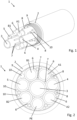
- FIG. 1 a charging cable 1 according to the present invention is shown, wherein in Figure 1 the charging cable 1 in a perspective view and in Figure 2 shown in a sectional view.
- the charging cable 1 for transmitting electrical energy has a sheathed cable 2 which encloses all components of the charging cable 1.
- a metal foil 9 is connected to an inner sheath surface of the sheathed cable 2, which can also be designed, for example, in the form of a metal foil or a metal-clad plastic film. The metal foil 9 therefore also encloses all components (except the sheathed cable 2) of the charging cable 1.
- the charging cable 1 also has five current conductor cables, namely a first current conductor cable A1, a second current conductor cable A2, a third current conductor cable B1 and a fourth current conductor cable B2, which in the illustrated embodiment are designed to transmit direct current, and a fifth current conductor cable PE designed as a protective conductor PE. All current conductor cables A1, A2, B1, B2, PE are each enclosed by an insulating sheath 6, so that the current conductor cables A1, A2, B1, B2, PE are not in electrical contact with their surroundings.
- a first current conductor pair consisting of the first current conductor cable A1 and the second current conductor cable A2 is assigned to a common first voltage potential.
- the first current conductor pair can, for example, be assigned to the positive pole in a charging cable 1 designed as a direct current charging cable 1.
- a second current conductor pair consisting of the third current conductor cable B1 and the fourth current conductor cable B2 is assigned to a common second voltage potential.
- the second current conductor pair can, for example, be assigned to the negative pole in a charging cable 1 designed as a direct current charging cable 1.
- the heat generated in the current conductor cables due to ohmic losses is transferred more effectively to the rest of the charging cable 1. Consequently, the power conductor cables A1, A2, B1, B2 have a lower temperature, so that larger charging currents can be transmitted with the power conductor cables A1, A2, B1, B2 without the power conductor cables A1, A2, B1, B2 and the charging cable 1 itself becoming excessively heated.
- the protective conductor PE is arranged between the second current conductor cable A2 and the fourth current conductor cable B2.
- the protective conductor PE can also be arranged between the first current conductor cable A1 and the third current conductor cable B1.
- the charging cable 1 further comprises three cooling lines 3, 4, 5 which are arranged within the sheathed line 2 and in each of which a cooling fluid channel is formed so that a cooling fluid can flow through the cooling lines 3, 4, 5.
- the first cooling line 3 is designed as a central cooling line 3.
- the central cooling line 3 is in direct contact with each of the power conductor cables A1, A2, B1, B2, PE.
- the second cooling line 4 is in direct contact with the central cooling line 3 as well as with the first power conductor cable A1 and the second power conductor cable A2.
- the third cooling line 5 is in direct contact with the central cooling line 3 as well as with the third power conductor cable B1 and the fourth power conductor cable B2. Due to the direct contact of the power cables A1, A2, B1, B2, PE with the cooling lines 3, 4, 5, the heat generated in the power cables A1, A2, B1, B2, PE is effectively dissipated by means of a cooling fluid flow within the cooling lines 3, 4, 5.
- the central cooling line 3 is in indirect contact with each of the power conductor cables A1, A2, B1, B2, PE by means of at least one strain relief cable 7 arranged between the central cooling line 3 and the respective power conductor cable A1, A2, B1, B2, PE.
- the respective strain relief cables 7 can be designed, for example, as aramid fiber cables 7.
- the central cooling line 3 is arranged centrally within the sheathed line 2 and that in the cross section of the charging cable 1 the central cooling line 3 is surrounded in a star shape by all the current conductor cables A1, A2, B1, B2, PE and by the second cooling line 4 and the third cooling line 5.
- the current conductor cables A1, A2, B1, B2, PE, the second cooling line 4 and the third cooling line 5 are thus arranged at an angular equidistant distance around the central cooling line 3 and are each in direct contact with the central cooling line 3.
- the charging cable 1 further comprises a plurality of signal lines 8, which are arranged between two current conductor cables A1, A2, B1, B2, PE that are directly adjacent to one another and in direct contact with one another.
- the signal lines 8 are also in direct contact with the current conductor cables A1, A2, B1, B2, PE E.
- some of the signal lines 8 are arranged between a power cable A1, A2, B1, B2, PE and the second cooling line 4 or the third cooling line 5 which are in direct contact with that power cable A1, A2, B1, B2, PE, and are in direct contact with the respective power cable A1, A2, B1, B2, PE and the second cooling line 4 or the third cooling line 5.
- the charging cable 1 according to the invention further comprises a plurality of filling strands 10, which are also referred to as filling cables 10.
- the filling strands 10 can be formed from a fiber material, for example from a cotton fiber fabric.
Landscapes
- Engineering & Computer Science (AREA)
- Power Engineering (AREA)
- Transportation (AREA)
- Mechanical Engineering (AREA)
- Electric Propulsion And Braking For Vehicles (AREA)
- Insulated Conductors (AREA)
- Charge And Discharge Circuits For Batteries Or The Like (AREA)
Applications Claiming Priority (2)
| Application Number | Priority Date | Filing Date | Title |
|---|---|---|---|
| DE102016209607.9A DE102016209607A1 (de) | 2016-06-01 | 2016-06-01 | Ladekabel zur Übertragung elektrischer Energie, Ladestecker und Ladestation zur Abgabe elektrischer Energie an einen Empfänger elektrischer Energie |
| PCT/EP2017/061716 WO2017207266A1 (de) | 2016-06-01 | 2017-05-16 | Ladekabel zur übertragung elektrischer energie, ladestecker und ladestation zur abgabe elektrischer energie an einen empfänger elektrischer energie |
Publications (2)
| Publication Number | Publication Date |
|---|---|
| EP3465699A1 EP3465699A1 (de) | 2019-04-10 |
| EP3465699B1 true EP3465699B1 (de) | 2024-08-14 |
Family
ID=58745216
Family Applications (1)
| Application Number | Title | Priority Date | Filing Date |
|---|---|---|---|
| EP17724793.9A Active EP3465699B1 (de) | 2016-06-01 | 2017-05-16 | Ladekabel zur übertragung elektrischer energie, ladestecker und ladestation zur abgabe elektrischer energie an einen empfänger elektrischer energie |
Country Status (7)
| Country | Link |
|---|---|
| US (1) | US11349230B2 (pl) |
| EP (1) | EP3465699B1 (pl) |
| JP (1) | JP6876726B2 (pl) |
| CN (1) | CN109313966B (pl) |
| DE (1) | DE102016209607A1 (pl) |
| PL (1) | PL3465699T3 (pl) |
| WO (1) | WO2017207266A1 (pl) |
Families Citing this family (27)
| Publication number | Priority date | Publication date | Assignee | Title |
|---|---|---|---|---|
| DE102017105985A1 (de) * | 2017-03-21 | 2018-09-27 | Dr. Ing. H.C. F. Porsche Aktiengesellschaft | Ladekabelanordnung |
| DE102017115241A1 (de) * | 2017-07-07 | 2019-01-10 | Paxos Consulting & Engineering GmbH & Co. KG | Ladekabelsystem mit Kühlung |
| US11084390B2 (en) | 2018-03-22 | 2021-08-10 | Tesla, Inc. | Liquid-cooled charging connector |
| ES2927551T3 (es) * | 2018-04-02 | 2022-11-08 | Rocking Energy Intelligent Tech Co Ltd | Pistola de carga que presenta un excelente rendimiento de conducción y disipación de calor |
| FR3094552A1 (fr) * | 2019-03-29 | 2020-10-02 | Acome Societe Cooperative Et Participative Sa Cooperative De Production A Capital Variable | Dispositif de charge pour véhicule électrique à dissipation thermique améliorée |
| DE102019112843B3 (de) * | 2019-05-16 | 2020-09-03 | Dr. Ing. H.C. F. Porsche Aktiengesellschaft | Kraftfahrzeugladekabel |
| EP3770925B1 (en) * | 2019-07-25 | 2023-12-27 | ABB E-mobility B.V. | Heavy-current charging cable for charging an electric vehicle |
| US11147193B2 (en) * | 2020-02-25 | 2021-10-12 | GM Global Technology Operations LLC | Vascular cooling system for electrical conductors |
| EP4154282A1 (en) * | 2020-05-18 | 2023-03-29 | CommScope Technologies LLC | Cable for distributing network power and data |
| JP7463859B2 (ja) * | 2020-06-08 | 2024-04-09 | 株式会社オートネットワーク技術研究所 | ワイヤハーネスユニット |
| JP7463860B2 (ja) * | 2020-06-08 | 2024-04-09 | 株式会社オートネットワーク技術研究所 | ワイヤハーネスユニット |
| JP7463862B2 (ja) * | 2020-06-08 | 2024-04-09 | 株式会社オートネットワーク技術研究所 | ワイヤハーネスユニット |
| JP7480638B2 (ja) * | 2020-08-26 | 2024-05-10 | 住友電装株式会社 | ワイヤハーネスユニット |
| JP7524672B2 (ja) * | 2020-08-26 | 2024-07-30 | 住友電装株式会社 | ワイヤハーネスユニット |
| IL278084B2 (en) * | 2020-10-15 | 2025-02-01 | Green Business Dev Ltd | Vehicle charging cable and method of manufacturing |
| CN112271022A (zh) * | 2020-10-20 | 2021-01-26 | 中国电力科学研究院有限公司 | 冷却线缆和充电设备 |
| CN112530636B (zh) * | 2020-11-09 | 2022-04-22 | 临沂矿业集团有限责任公司 | 一种智能化采煤机专用电缆 |
| WO2022226730A1 (zh) * | 2021-04-26 | 2022-11-03 | 浙江吉利控股集团有限公司 | 一种液冷充电电缆及电动车充电桩 |
| US11640861B2 (en) * | 2021-05-10 | 2023-05-02 | Te Connectivity Solutions Gmbh | Power cable which reduces skin effect and proximity effect |
| DE102021114495A1 (de) | 2021-06-07 | 2022-12-08 | Phoenix Contact E-Mobility Gmbh | Kabel mit aktiver Kühlung |
| LU500252B1 (de) | 2021-06-07 | 2022-12-08 | Phoenix Contact E Mobility Gmbh | Kabel mit aktiver Kühlung |
| CN113380451A (zh) * | 2021-07-14 | 2021-09-10 | 浙江吉利控股集团有限公司 | 充电电缆 |
| US12107373B2 (en) | 2021-07-15 | 2024-10-01 | Japan Aviation Electronics Industry, Limited | Assembly including a cable and a connector with second coupling portion of each DC contact of connector coupled with first coupling portions of at least two DC wires of cable |
| EP4147903A1 (en) * | 2021-09-14 | 2023-03-15 | ABB E-mobility B.V. | Charging cable for charging an electric vehicle, and electric vehicle supply equipment with a charging cable |
| EP4163934A1 (en) * | 2021-10-11 | 2023-04-12 | Aptiv Technologies Limited | High voltage power cable |
| DE102022134062A1 (de) | 2022-12-20 | 2024-06-20 | Phoenix Contact E-Mobility Gmbh | Steckverbinder mit kühlkörper, kabel mit kühlkanal, anordnung mit einem steckverbinder und mit einem kabel, sowie verfahren zur kühlung eines steckverbinders |
| KR102907565B1 (ko) * | 2023-08-29 | 2026-01-02 | 주식회사 현대케피코 | 전기 자동차 충전용 케이블 |
Citations (6)
| Publication number | Priority date | Publication date | Assignee | Title |
|---|---|---|---|---|
| DE9319131U1 (de) * | 1993-12-09 | 1994-07-07 | Siemens AG, 80333 München | Flexible Starkstromleitung mit einem mehradrigen Kernelement und sechs stromführenden Adern |
| DE202007012165U1 (de) * | 2007-08-31 | 2007-11-22 | Nexans | Flexible elektrische Leitung |
| US20150107874A1 (en) * | 2012-07-05 | 2015-04-23 | Green ELMF Cables Ltd. | Electric cables having self-protective properties and immunity to magnetic interferences |
| DE202014000328U1 (de) * | 2014-01-17 | 2015-05-06 | Leoni Bordnetz-Systeme Gmbh | Ladesystem zum Laden eines Energiespeichers eines Elektrofahrzeuges und Ladekabel hierfür |
| US20150217654A1 (en) * | 2014-02-05 | 2015-08-06 | Tesla Motors, Inc. | Cooling of charging cable |
| DE102015114133A1 (de) * | 2015-08-26 | 2017-03-02 | Phoenix Contact E-Mobility Gmbh | Stromkabel mit einer Kühlleitung |
Family Cites Families (24)
| Publication number | Priority date | Publication date | Assignee | Title |
|---|---|---|---|---|
| FR1164751A (fr) * | 1957-01-15 | 1958-10-14 | Comp Generale Electricite | Corde axiale d'acier porteuse à plusieurs fils pour câble sous-marin |
| JPS60226713A (ja) | 1984-04-21 | 1985-11-12 | 株式会社フジクラ | 電力ケ−ブルの冷却方法 |
| DE3528585A1 (de) * | 1985-08-06 | 1987-02-19 | Siemens Ag | Flexible elektrische leitung |
| JPS63114383A (ja) | 1986-10-30 | 1988-05-19 | Nec Corp | 映像信号の時間軸変換回路 |
| JPH0234023U (pl) * | 1988-08-29 | 1990-03-05 | ||
| EP0823767A1 (en) * | 1996-08-07 | 1998-02-11 | SUMITOMO WIRING SYSTEMS, Ltd. | Charging system for electric vehicle |
| JP2001160322A (ja) * | 1999-12-02 | 2001-06-12 | Toyota Autom Loom Works Ltd | 給電用ケーブル |
| JP2005339928A (ja) | 2004-05-26 | 2005-12-08 | Nissan Motor Co Ltd | モーター駆動制御用複合ケーブルおよびインバーター |
| TWM340532U (en) * | 2008-01-15 | 2008-09-11 | Zheng-Xiong Wu | Energy-saving electric wire and cable |
| FR2946789B1 (fr) * | 2009-06-11 | 2017-01-13 | Nexans | Cable electrique apte a assurer la continuite de distribution electrique en cas d'incendie. |
| DE102010033441A1 (de) * | 2010-08-04 | 2012-02-09 | Phoenix Contact Gmbh & Co. Kg | Kabelanordnung |
| CN103262177B (zh) * | 2010-12-15 | 2015-07-01 | Abb技术有限公司 | 高压电缆 |
| US8350526B2 (en) * | 2011-07-25 | 2013-01-08 | Lightening Energy | Station for rapidly charging an electric vehicle battery |
| US9779856B2 (en) * | 2012-02-20 | 2017-10-03 | Aker Solutions As | Arrangement for cooling power cables, power umbilicals and cables |
| TWI452122B (zh) | 2012-02-24 | 2014-09-11 | Dainippon Ink & Chemicals | 液晶組成物 |
| CN202855346U (zh) * | 2012-10-25 | 2013-04-03 | 大连德昌线缆有限公司 | 大电流小外径环保节能型串行总线 |
| JP6080126B2 (ja) | 2013-04-23 | 2017-02-15 | 矢崎総業株式会社 | シールド機能付き電線 |
| JP2015082340A (ja) * | 2013-10-21 | 2015-04-27 | 矢崎総業株式会社 | 充電コネクタ |
| NO340781B1 (no) * | 2013-11-18 | 2017-06-19 | Nexans | Kabel for nedihullspumpe |
| JP2015159694A (ja) * | 2014-02-25 | 2015-09-03 | 住友電装株式会社 | 電線の冷却装置 |
| CN104112508A (zh) * | 2014-07-12 | 2014-10-22 | 惠州市以泰克电线工业有限公司 | 一种新型电动汽车内部用电缆及其制备方法 |
| CN105575559B (zh) * | 2014-10-13 | 2017-09-26 | 国家电网公司 | 一种输电用多电缆组装装置及使用方法 |
| DE202015009532U1 (de) * | 2015-11-19 | 2018-02-27 | Dr. Ing. H.C. F. Porsche Aktiengesellschaft | Elektrische Leitungsanordnung |
| CN205158923U (zh) * | 2015-12-07 | 2016-04-13 | 福建世纪电缆有限公司 | 一种电动汽车传导充电系统用电缆 |
-
2016
- 2016-06-01 DE DE102016209607.9A patent/DE102016209607A1/de not_active Ceased
-
2017
- 2017-05-16 CN CN201780033945.5A patent/CN109313966B/zh active Active
- 2017-05-16 EP EP17724793.9A patent/EP3465699B1/de active Active
- 2017-05-16 US US16/303,925 patent/US11349230B2/en active Active
- 2017-05-16 JP JP2018562991A patent/JP6876726B2/ja not_active Expired - Fee Related
- 2017-05-16 PL PL17724793.9T patent/PL3465699T3/pl unknown
- 2017-05-16 WO PCT/EP2017/061716 patent/WO2017207266A1/de not_active Ceased
Patent Citations (6)
| Publication number | Priority date | Publication date | Assignee | Title |
|---|---|---|---|---|
| DE9319131U1 (de) * | 1993-12-09 | 1994-07-07 | Siemens AG, 80333 München | Flexible Starkstromleitung mit einem mehradrigen Kernelement und sechs stromführenden Adern |
| DE202007012165U1 (de) * | 2007-08-31 | 2007-11-22 | Nexans | Flexible elektrische Leitung |
| US20150107874A1 (en) * | 2012-07-05 | 2015-04-23 | Green ELMF Cables Ltd. | Electric cables having self-protective properties and immunity to magnetic interferences |
| DE202014000328U1 (de) * | 2014-01-17 | 2015-05-06 | Leoni Bordnetz-Systeme Gmbh | Ladesystem zum Laden eines Energiespeichers eines Elektrofahrzeuges und Ladekabel hierfür |
| US20150217654A1 (en) * | 2014-02-05 | 2015-08-06 | Tesla Motors, Inc. | Cooling of charging cable |
| DE102015114133A1 (de) * | 2015-08-26 | 2017-03-02 | Phoenix Contact E-Mobility Gmbh | Stromkabel mit einer Kühlleitung |
Also Published As
| Publication number | Publication date |
|---|---|
| WO2017207266A1 (de) | 2017-12-07 |
| EP3465699A1 (de) | 2019-04-10 |
| JP6876726B2 (ja) | 2021-05-26 |
| DE102016209607A1 (de) | 2017-12-07 |
| JP2019519073A (ja) | 2019-07-04 |
| US20200317070A1 (en) | 2020-10-08 |
| PL3465699T3 (pl) | 2024-11-18 |
| CN109313966B (zh) | 2021-08-24 |
| US11349230B2 (en) | 2022-05-31 |
| CN109313966A (zh) | 2019-02-05 |
Similar Documents
| Publication | Publication Date | Title |
|---|---|---|
| EP3465699B1 (de) | Ladekabel zur übertragung elektrischer energie, ladestecker und ladestation zur abgabe elektrischer energie an einen empfänger elektrischer energie | |
| EP3520122B1 (de) | Elektrisches kabel mit einer kühlmittelleitung | |
| EP3443566B1 (de) | Ladekabel zur übertragung elektrischer energie, ladestecker und ladestation zur abgabe elektrischer energie an einen empfänger elektrischer energie | |
| EP3433902B1 (de) | Steckverbinderteil mit einem gekühlten kontaktelement | |
| DE102016206300B4 (de) | Ladestecker und ladestation zur abgabe elektrischer energie an einen empfänger elektrischer energie | |
| DE102018102207A1 (de) | Kraftfahrzeugladekabel | |
| EP3330976A1 (de) | Hochstromkabel und stromversorgungssystem mit hochstromkabel | |
| LU500252B1 (de) | Kabel mit aktiver Kühlung | |
| EP3767752B1 (de) | Konfektioniertes elektrisches kabel, verfahren zur konfektionierung eines elektrischen kabels und elektrische steckverbindung | |
| DE102018125835A1 (de) | Kabelbaugruppe mit einer Kühlleitung und einer Zugentlastungsbaugruppe | |
| DE102020120819A1 (de) | Gekühltes Ladekabel | |
| DE202015009535U1 (de) | Elektrisches Ladekabel für ein Kraftfahrzeug | |
| WO2021001093A1 (de) | Aktiv gekühltes ladesteckverbinderteil | |
| WO2024193890A1 (de) | Gekühltes ladekabel mit kühlung passiver leitungselemente | |
| DE102016205586A1 (de) | Datenbusstecker für hohe Datenraten | |
| DE102022134062A1 (de) | Steckverbinder mit kühlkörper, kabel mit kühlkanal, anordnung mit einem steckverbinder und mit einem kabel, sowie verfahren zur kühlung eines steckverbinders | |
| DE102022124506A1 (de) | Ladesteckverbinder für Elektro- und Hybridfahrzeuge | |
| DE202016008631U1 (de) | Flüssigkeitsgekühltes Kontaktelement | |
| DE102021114495A1 (de) | Kabel mit aktiver Kühlung | |
| DE102020133662A1 (de) | Kabelbaugruppe zum Übertragen eines elektrischen Stroms | |
| EP2899075B1 (de) | Kraftfahrzeugbatteriekabel | |
| DE102017129281A1 (de) | Flüssigkeitsgekühltes Kontaktelement | |
| DE202017102535U1 (de) | Ladekabel für Elektrofahrzeuge | |
| EP2525370A1 (de) | Hochfrequenzenergiekabel | |
| DE102024114628A1 (de) | Innenkonturschlauch |
Legal Events
| Date | Code | Title | Description |
|---|---|---|---|
| STAA | Information on the status of an ep patent application or granted ep patent |
Free format text: STATUS: UNKNOWN |
|
| STAA | Information on the status of an ep patent application or granted ep patent |
Free format text: STATUS: THE INTERNATIONAL PUBLICATION HAS BEEN MADE |
|
| PUAI | Public reference made under article 153(3) epc to a published international application that has entered the european phase |
Free format text: ORIGINAL CODE: 0009012 |
|
| STAA | Information on the status of an ep patent application or granted ep patent |
Free format text: STATUS: REQUEST FOR EXAMINATION WAS MADE |
|
| 17P | Request for examination filed |
Effective date: 20181204 |
|
| AK | Designated contracting states |
Kind code of ref document: A1 Designated state(s): AL AT BE BG CH CY CZ DE DK EE ES FI FR GB GR HR HU IE IS IT LI LT LU LV MC MK MT NL NO PL PT RO RS SE SI SK SM TR |
|
| AX | Request for extension of the european patent |
Extension state: BA ME |
|
| DAV | Request for validation of the european patent (deleted) | ||
| DAX | Request for extension of the european patent (deleted) | ||
| STAA | Information on the status of an ep patent application or granted ep patent |
Free format text: STATUS: EXAMINATION IS IN PROGRESS |
|
| 17Q | First examination report despatched |
Effective date: 20200514 |
|
| P01 | Opt-out of the competence of the unified patent court (upc) registered |
Effective date: 20230525 |
|
| P02 | Opt-out of the competence of the unified patent court (upc) changed |
Effective date: 20230531 |
|
| REG | Reference to a national code |
Ref legal event code: R079 Ipc: B60L0053160000 Ref country code: DE Ref legal event code: R079 Ref document number: 502017016347 Country of ref document: DE Free format text: PREVIOUS MAIN CLASS: H01B0007000000 Ipc: B60L0053160000 |
|
| GRAP | Despatch of communication of intention to grant a patent |
Free format text: ORIGINAL CODE: EPIDOSNIGR1 |
|
| STAA | Information on the status of an ep patent application or granted ep patent |
Free format text: STATUS: GRANT OF PATENT IS INTENDED |
|
| INTG | Intention to grant announced |
Effective date: 20240517 |
|
| RIC1 | Information provided on ipc code assigned before grant |
Ipc: H01B 9/00 20060101ALI20240503BHEP Ipc: H01B 7/42 20060101ALI20240503BHEP Ipc: H01R 9/05 20060101ALI20240503BHEP Ipc: B60L 53/18 20190101ALI20240503BHEP Ipc: B60L 53/16 20190101AFI20240503BHEP |
|
| GRAS | Grant fee paid |
Free format text: ORIGINAL CODE: EPIDOSNIGR3 |
|
| GRAA | (expected) grant |
Free format text: ORIGINAL CODE: 0009210 |
|
| STAA | Information on the status of an ep patent application or granted ep patent |
Free format text: STATUS: THE PATENT HAS BEEN GRANTED |
|
| AK | Designated contracting states |
Kind code of ref document: B1 Designated state(s): AL AT BE BG CH CY CZ DE DK EE ES FI FR GB GR HR HU IE IS IT LI LT LU LV MC MK MT NL NO PL PT RO RS SE SI SK SM TR |
|
| REG | Reference to a national code |
Ref country code: GB Ref legal event code: FG4D Free format text: NOT ENGLISH |
|
| REG | Reference to a national code |
Ref country code: CH Ref legal event code: EP |
|
| REG | Reference to a national code |
Ref country code: DE Ref legal event code: R096 Ref document number: 502017016347 Country of ref document: DE |
|
| REG | Reference to a national code |
Ref country code: IE Ref legal event code: FG4D Free format text: LANGUAGE OF EP DOCUMENT: GERMAN Ref country code: NL Ref legal event code: FP |
|
| REG | Reference to a national code |
Ref country code: LT Ref legal event code: MG9D |
|
| PG25 | Lapsed in a contracting state [announced via postgrant information from national office to epo] |
Ref country code: NO Free format text: LAPSE BECAUSE OF FAILURE TO SUBMIT A TRANSLATION OF THE DESCRIPTION OR TO PAY THE FEE WITHIN THE PRESCRIBED TIME-LIMIT Effective date: 20241114 |
|
| PG25 | Lapsed in a contracting state [announced via postgrant information from national office to epo] |
Ref country code: PT Free format text: LAPSE BECAUSE OF FAILURE TO SUBMIT A TRANSLATION OF THE DESCRIPTION OR TO PAY THE FEE WITHIN THE PRESCRIBED TIME-LIMIT Effective date: 20241216 Ref country code: FI Free format text: LAPSE BECAUSE OF FAILURE TO SUBMIT A TRANSLATION OF THE DESCRIPTION OR TO PAY THE FEE WITHIN THE PRESCRIBED TIME-LIMIT Effective date: 20240814 Ref country code: GR Free format text: LAPSE BECAUSE OF FAILURE TO SUBMIT A TRANSLATION OF THE DESCRIPTION OR TO PAY THE FEE WITHIN THE PRESCRIBED TIME-LIMIT Effective date: 20241115 |
|
| PG25 | Lapsed in a contracting state [announced via postgrant information from national office to epo] |
Ref country code: BG Free format text: LAPSE BECAUSE OF FAILURE TO SUBMIT A TRANSLATION OF THE DESCRIPTION OR TO PAY THE FEE WITHIN THE PRESCRIBED TIME-LIMIT Effective date: 20240814 |
|
| PG25 | Lapsed in a contracting state [announced via postgrant information from national office to epo] |
Ref country code: LV Free format text: LAPSE BECAUSE OF FAILURE TO SUBMIT A TRANSLATION OF THE DESCRIPTION OR TO PAY THE FEE WITHIN THE PRESCRIBED TIME-LIMIT Effective date: 20240814 |
|
| PG25 | Lapsed in a contracting state [announced via postgrant information from national office to epo] |
Ref country code: IS Free format text: LAPSE BECAUSE OF FAILURE TO SUBMIT A TRANSLATION OF THE DESCRIPTION OR TO PAY THE FEE WITHIN THE PRESCRIBED TIME-LIMIT Effective date: 20241214 |
|
| PG25 | Lapsed in a contracting state [announced via postgrant information from national office to epo] |
Ref country code: HR Free format text: LAPSE BECAUSE OF FAILURE TO SUBMIT A TRANSLATION OF THE DESCRIPTION OR TO PAY THE FEE WITHIN THE PRESCRIBED TIME-LIMIT Effective date: 20240814 |
|
| PG25 | Lapsed in a contracting state [announced via postgrant information from national office to epo] |
Ref country code: RS Free format text: LAPSE BECAUSE OF FAILURE TO SUBMIT A TRANSLATION OF THE DESCRIPTION OR TO PAY THE FEE WITHIN THE PRESCRIBED TIME-LIMIT Effective date: 20241114 Ref country code: ES Free format text: LAPSE BECAUSE OF FAILURE TO SUBMIT A TRANSLATION OF THE DESCRIPTION OR TO PAY THE FEE WITHIN THE PRESCRIBED TIME-LIMIT Effective date: 20240814 |
|
| PG25 | Lapsed in a contracting state [announced via postgrant information from national office to epo] |
Ref country code: RS Free format text: LAPSE BECAUSE OF FAILURE TO SUBMIT A TRANSLATION OF THE DESCRIPTION OR TO PAY THE FEE WITHIN THE PRESCRIBED TIME-LIMIT Effective date: 20241114 Ref country code: PT Free format text: LAPSE BECAUSE OF FAILURE TO SUBMIT A TRANSLATION OF THE DESCRIPTION OR TO PAY THE FEE WITHIN THE PRESCRIBED TIME-LIMIT Effective date: 20241216 Ref country code: NO Free format text: LAPSE BECAUSE OF FAILURE TO SUBMIT A TRANSLATION OF THE DESCRIPTION OR TO PAY THE FEE WITHIN THE PRESCRIBED TIME-LIMIT Effective date: 20241114 Ref country code: LV Free format text: LAPSE BECAUSE OF FAILURE TO SUBMIT A TRANSLATION OF THE DESCRIPTION OR TO PAY THE FEE WITHIN THE PRESCRIBED TIME-LIMIT Effective date: 20240814 Ref country code: IS Free format text: LAPSE BECAUSE OF FAILURE TO SUBMIT A TRANSLATION OF THE DESCRIPTION OR TO PAY THE FEE WITHIN THE PRESCRIBED TIME-LIMIT Effective date: 20241214 Ref country code: HR Free format text: LAPSE BECAUSE OF FAILURE TO SUBMIT A TRANSLATION OF THE DESCRIPTION OR TO PAY THE FEE WITHIN THE PRESCRIBED TIME-LIMIT Effective date: 20240814 Ref country code: GR Free format text: LAPSE BECAUSE OF FAILURE TO SUBMIT A TRANSLATION OF THE DESCRIPTION OR TO PAY THE FEE WITHIN THE PRESCRIBED TIME-LIMIT Effective date: 20241115 Ref country code: FI Free format text: LAPSE BECAUSE OF FAILURE TO SUBMIT A TRANSLATION OF THE DESCRIPTION OR TO PAY THE FEE WITHIN THE PRESCRIBED TIME-LIMIT Effective date: 20240814 Ref country code: ES Free format text: LAPSE BECAUSE OF FAILURE TO SUBMIT A TRANSLATION OF THE DESCRIPTION OR TO PAY THE FEE WITHIN THE PRESCRIBED TIME-LIMIT Effective date: 20240814 Ref country code: BG Free format text: LAPSE BECAUSE OF FAILURE TO SUBMIT A TRANSLATION OF THE DESCRIPTION OR TO PAY THE FEE WITHIN THE PRESCRIBED TIME-LIMIT Effective date: 20240814 |
|
| PG25 | Lapsed in a contracting state [announced via postgrant information from national office to epo] |
Ref country code: RO Free format text: LAPSE BECAUSE OF FAILURE TO SUBMIT A TRANSLATION OF THE DESCRIPTION OR TO PAY THE FEE WITHIN THE PRESCRIBED TIME-LIMIT Effective date: 20240814 Ref country code: SM Free format text: LAPSE BECAUSE OF FAILURE TO SUBMIT A TRANSLATION OF THE DESCRIPTION OR TO PAY THE FEE WITHIN THE PRESCRIBED TIME-LIMIT Effective date: 20240814 Ref country code: DK Free format text: LAPSE BECAUSE OF FAILURE TO SUBMIT A TRANSLATION OF THE DESCRIPTION OR TO PAY THE FEE WITHIN THE PRESCRIBED TIME-LIMIT Effective date: 20240814 |
|
| PG25 | Lapsed in a contracting state [announced via postgrant information from national office to epo] |
Ref country code: EE Free format text: LAPSE BECAUSE OF FAILURE TO SUBMIT A TRANSLATION OF THE DESCRIPTION OR TO PAY THE FEE WITHIN THE PRESCRIBED TIME-LIMIT Effective date: 20240814 |
|
| PG25 | Lapsed in a contracting state [announced via postgrant information from national office to epo] |
Ref country code: CZ Free format text: LAPSE BECAUSE OF FAILURE TO SUBMIT A TRANSLATION OF THE DESCRIPTION OR TO PAY THE FEE WITHIN THE PRESCRIBED TIME-LIMIT Effective date: 20240814 |
|
| PG25 | Lapsed in a contracting state [announced via postgrant information from national office to epo] |
Ref country code: SK Free format text: LAPSE BECAUSE OF FAILURE TO SUBMIT A TRANSLATION OF THE DESCRIPTION OR TO PAY THE FEE WITHIN THE PRESCRIBED TIME-LIMIT Effective date: 20240814 |
|
| REG | Reference to a national code |
Ref country code: DE Ref legal event code: R097 Ref document number: 502017016347 Country of ref document: DE |
|
| PGFP | Annual fee paid to national office [announced via postgrant information from national office to epo] |
Ref country code: NL Payment date: 20250526 Year of fee payment: 9 |
|
| PLBE | No opposition filed within time limit |
Free format text: ORIGINAL CODE: 0009261 |
|
| STAA | Information on the status of an ep patent application or granted ep patent |
Free format text: STATUS: NO OPPOSITION FILED WITHIN TIME LIMIT |
|
| PGFP | Annual fee paid to national office [announced via postgrant information from national office to epo] |
Ref country code: IT Payment date: 20250522 Year of fee payment: 9 |
|
| 26N | No opposition filed |
Effective date: 20250515 |
|
| PG25 | Lapsed in a contracting state [announced via postgrant information from national office to epo] |
Ref country code: SE Free format text: LAPSE BECAUSE OF FAILURE TO SUBMIT A TRANSLATION OF THE DESCRIPTION OR TO PAY THE FEE WITHIN THE PRESCRIBED TIME-LIMIT Effective date: 20240814 |
|
| PGFP | Annual fee paid to national office [announced via postgrant information from national office to epo] |
Ref country code: DE Payment date: 20250728 Year of fee payment: 9 |
|
| PGFP | Annual fee paid to national office [announced via postgrant information from national office to epo] |
Ref country code: PL Payment date: 20250514 Year of fee payment: 9 |
|
| REG | Reference to a national code |
Ref country code: CH Ref legal event code: H13 Free format text: ST27 STATUS EVENT CODE: U-0-0-H10-H13 (AS PROVIDED BY THE NATIONAL OFFICE) Effective date: 20251223 |
|
| PG25 | Lapsed in a contracting state [announced via postgrant information from national office to epo] |
Ref country code: LU Free format text: LAPSE BECAUSE OF NON-PAYMENT OF DUE FEES Effective date: 20250516 |
|
| PG25 | Lapsed in a contracting state [announced via postgrant information from national office to epo] |
Ref country code: CH Free format text: LAPSE BECAUSE OF NON-PAYMENT OF DUE FEES Effective date: 20250531 |
|
| GBPC | Gb: european patent ceased through non-payment of renewal fee |
Effective date: 20250516 |
|
| REG | Reference to a national code |
Ref country code: BE Ref legal event code: MM Effective date: 20250531 |
|
| PG25 | Lapsed in a contracting state [announced via postgrant information from national office to epo] |
Ref country code: MC Free format text: LAPSE BECAUSE OF FAILURE TO SUBMIT A TRANSLATION OF THE DESCRIPTION OR TO PAY THE FEE WITHIN THE PRESCRIBED TIME-LIMIT Effective date: 20240814 |