EP3465699B1 - Ladekabel zur übertragung elektrischer energie, ladestecker und ladestation zur abgabe elektrischer energie an einen empfänger elektrischer energie - Google Patents
Ladekabel zur übertragung elektrischer energie, ladestecker und ladestation zur abgabe elektrischer energie an einen empfänger elektrischer energie Download PDFInfo
- Publication number
- EP3465699B1 EP3465699B1 EP17724793.9A EP17724793A EP3465699B1 EP 3465699 B1 EP3465699 B1 EP 3465699B1 EP 17724793 A EP17724793 A EP 17724793A EP 3465699 B1 EP3465699 B1 EP 3465699B1
- Authority
- EP
- European Patent Office
- Prior art keywords
- cable
- cooling line
- current conductor
- charging
- conductor cable
- Prior art date
- Legal status (The legal status is an assumption and is not a legal conclusion. Google has not performed a legal analysis and makes no representation as to the accuracy of the status listed.)
- Active
Links
Images
Classifications
-
- H—ELECTRICITY
- H01—ELECTRIC ELEMENTS
- H01R—ELECTRICALLY-CONDUCTIVE CONNECTIONS; STRUCTURAL ASSOCIATIONS OF A PLURALITY OF MUTUALLY-INSULATED ELECTRICAL CONNECTING ELEMENTS; COUPLING DEVICES; CURRENT COLLECTORS
- H01R9/00—Structural associations of a plurality of mutually-insulated electrical connecting elements, e.g. terminal strips or terminal blocks; Terminals or binding posts mounted upon a base or in a case; Bases therefor
- H01R9/03—Connectors arranged to contact a plurality of the conductors of a multiconductor cable, e.g. tapping connections
- H01R9/05—Connectors arranged to contact a plurality of the conductors of a multiconductor cable, e.g. tapping connections for coaxial cables
-
- B—PERFORMING OPERATIONS; TRANSPORTING
- B60—VEHICLES IN GENERAL
- B60L—PROPULSION OF ELECTRICALLY-PROPELLED VEHICLES; SUPPLYING ELECTRIC POWER FOR AUXILIARY EQUIPMENT OF ELECTRICALLY-PROPELLED VEHICLES; ELECTRODYNAMIC BRAKE SYSTEMS FOR VEHICLES IN GENERAL; MAGNETIC SUSPENSION OR LEVITATION FOR VEHICLES; MONITORING OPERATING VARIABLES OF ELECTRICALLY-PROPELLED VEHICLES; ELECTRIC SAFETY DEVICES FOR ELECTRICALLY-PROPELLED VEHICLES
- B60L53/00—Methods of charging batteries, specially adapted for electric vehicles; Charging stations or on-board charging equipment therefor; Exchange of energy storage elements in electric vehicles
- B60L53/10—Methods of charging batteries, specially adapted for electric vehicles; Charging stations or on-board charging equipment therefor; Exchange of energy storage elements in electric vehicles characterised by the energy transfer between the charging station and the vehicle
- B60L53/14—Conductive energy transfer
- B60L53/16—Connectors, e.g. plugs or sockets, specially adapted for charging electric vehicles
-
- B—PERFORMING OPERATIONS; TRANSPORTING
- B60—VEHICLES IN GENERAL
- B60L—PROPULSION OF ELECTRICALLY-PROPELLED VEHICLES; SUPPLYING ELECTRIC POWER FOR AUXILIARY EQUIPMENT OF ELECTRICALLY-PROPELLED VEHICLES; ELECTRODYNAMIC BRAKE SYSTEMS FOR VEHICLES IN GENERAL; MAGNETIC SUSPENSION OR LEVITATION FOR VEHICLES; MONITORING OPERATING VARIABLES OF ELECTRICALLY-PROPELLED VEHICLES; ELECTRIC SAFETY DEVICES FOR ELECTRICALLY-PROPELLED VEHICLES
- B60L53/00—Methods of charging batteries, specially adapted for electric vehicles; Charging stations or on-board charging equipment therefor; Exchange of energy storage elements in electric vehicles
- B60L53/10—Methods of charging batteries, specially adapted for electric vehicles; Charging stations or on-board charging equipment therefor; Exchange of energy storage elements in electric vehicles characterised by the energy transfer between the charging station and the vehicle
- B60L53/14—Conductive energy transfer
- B60L53/18—Cables specially adapted for charging electric vehicles
-
- H—ELECTRICITY
- H01—ELECTRIC ELEMENTS
- H01B—CABLES; CONDUCTORS; INSULATORS; SELECTION OF MATERIALS FOR THEIR CONDUCTIVE, INSULATING OR DIELECTRIC PROPERTIES
- H01B9/00—Power cables
- H01B9/006—Constructional features relating to the conductors
-
- H—ELECTRICITY
- H01—ELECTRIC ELEMENTS
- H01B—CABLES; CONDUCTORS; INSULATORS; SELECTION OF MATERIALS FOR THEIR CONDUCTIVE, INSULATING OR DIELECTRIC PROPERTIES
- H01B9/00—Power cables
- H01B9/02—Power cables with screens or conductive layers, e.g. for avoiding large potential gradients
-
- H—ELECTRICITY
- H01—ELECTRIC ELEMENTS
- H01B—CABLES; CONDUCTORS; INSULATORS; SELECTION OF MATERIALS FOR THEIR CONDUCTIVE, INSULATING OR DIELECTRIC PROPERTIES
- H01B7/00—Insulated conductors or cables characterised by their form
- H01B7/42—Insulated conductors or cables characterised by their form with arrangements for heat dissipation or conduction
- H01B7/421—Insulated conductors or cables characterised by their form with arrangements for heat dissipation or conduction for heat dissipation
- H01B7/423—Insulated conductors or cables characterised by their form with arrangements for heat dissipation or conduction for heat dissipation using a cooling fluid
- H01B7/425—Insulated conductors or cables characterised by their form with arrangements for heat dissipation or conduction for heat dissipation using a cooling fluid the construction being bendable
-
- Y—GENERAL TAGGING OF NEW TECHNOLOGICAL DEVELOPMENTS; GENERAL TAGGING OF CROSS-SECTIONAL TECHNOLOGIES SPANNING OVER SEVERAL SECTIONS OF THE IPC; TECHNICAL SUBJECTS COVERED BY FORMER USPC CROSS-REFERENCE ART COLLECTIONS [XRACs] AND DIGESTS
- Y02—TECHNOLOGIES OR APPLICATIONS FOR MITIGATION OR ADAPTATION AGAINST CLIMATE CHANGE
- Y02T—CLIMATE CHANGE MITIGATION TECHNOLOGIES RELATED TO TRANSPORTATION
- Y02T10/00—Road transport of goods or passengers
- Y02T10/60—Other road transportation technologies with climate change mitigation effect
- Y02T10/70—Energy storage systems for electromobility, e.g. batteries
-
- Y—GENERAL TAGGING OF NEW TECHNOLOGICAL DEVELOPMENTS; GENERAL TAGGING OF CROSS-SECTIONAL TECHNOLOGIES SPANNING OVER SEVERAL SECTIONS OF THE IPC; TECHNICAL SUBJECTS COVERED BY FORMER USPC CROSS-REFERENCE ART COLLECTIONS [XRACs] AND DIGESTS
- Y02—TECHNOLOGIES OR APPLICATIONS FOR MITIGATION OR ADAPTATION AGAINST CLIMATE CHANGE
- Y02T—CLIMATE CHANGE MITIGATION TECHNOLOGIES RELATED TO TRANSPORTATION
- Y02T10/00—Road transport of goods or passengers
- Y02T10/60—Other road transportation technologies with climate change mitigation effect
- Y02T10/7072—Electromobility specific charging systems or methods for batteries, ultracapacitors, supercapacitors or double-layer capacitors
-
- Y—GENERAL TAGGING OF NEW TECHNOLOGICAL DEVELOPMENTS; GENERAL TAGGING OF CROSS-SECTIONAL TECHNOLOGIES SPANNING OVER SEVERAL SECTIONS OF THE IPC; TECHNICAL SUBJECTS COVERED BY FORMER USPC CROSS-REFERENCE ART COLLECTIONS [XRACs] AND DIGESTS
- Y02—TECHNOLOGIES OR APPLICATIONS FOR MITIGATION OR ADAPTATION AGAINST CLIMATE CHANGE
- Y02T—CLIMATE CHANGE MITIGATION TECHNOLOGIES RELATED TO TRANSPORTATION
- Y02T90/00—Enabling technologies or technologies with a potential or indirect contribution to GHG emissions mitigation
- Y02T90/10—Technologies relating to charging of electric vehicles
- Y02T90/14—Plug-in electric vehicles
Definitions
- the present invention relates to a charging cable for transmitting electrical energy, which is used in particular for transmitting electrical energy when charging an electric vehicle.
- the present invention also relates to a charging plug for coupling to a corresponding connection device and for transmitting electrical energy.
- the present invention also relates to a charging station for delivering electrical energy to a receiver of electrical energy.
- Charging cables for transmitting electrical energy are known from the state of the art. These have two power cables, each assigned to a different voltage potential, which are enclosed in a sheathed cable. When electrical currents are transmitted via the power cables, they heat up due to ohmic losses within the power cables. When the power cables heat up, the ohmic resistance of the power cables increases, so that the heating of the power cables then takes place at an accelerated rate.
- the charging cables Due to the charging current flowing through the charging cables, the charging cables inevitably heat up due to ohmic current heat losses.
- the heating of the charging cables is limited to a limit temperature increase.
- the limit temperature increase is limited to 50K.
- the DE 35 28 585 A1 a cutting line with an integrated water hose is known, whereby the water hose is arranged in the center of the line.
- Three energy wires of the line are each divided into two sub-wires, whereby these six sub-wires are stranded together with combined control/monitoring wires in a symmetrical arrangement in a single layer on the water hose.
- Each sub-wire consists of a conductor, the insulation and an outer conductive layer.
- Each control/monitoring core consists of a core element with a supporting thread, a plastic sheath and a concentrically applied control conductor, insulation and a concentric monitoring conductor applied to it with an extruded outer conductive layer arranged above it.
- the inner sheath and the outer sheath are applied to the stranded structure with a foil covering in between.
- a metallic braid made of a mixture of copper and steel wires is embedded in the outer sheath, which also forms the protective conductor of the cable.
- document WO 2015/060294 A1 relates to a charging connector having a power supply side terminal connected to the power supply side, an inner housing accommodating the power supply side terminal, an intermediate terminal having a power supply terminal portion electrically connectable to and disconnectable from the power supply side terminal, and an inlet terminal portion electrically connectable to and disconnectable from an inlet side terminal connected to the vehicle inlet side.
- a cassette housing accommodating the intermediate terminal and mounted to the inner housing can be installed in the vehicle inlet.
- US 2015/217654 A1 relates to a charging system for an electric vehicle comprising: a power supply; a cable having a first and a second end, the first end being connected to the power supply, the cable comprising a charging conductor and a cooling conduit, each extending from the first end to the second end; and a connector attached to the second end of the cable, the connector having a form factor corresponding to a charging port of the electric vehicle; the cooling conduit being adapted to carry a fluid that cools the charging conductor.
- the present invention is based on the object of providing a charging cable which enables increased charging currents with limited heating, and consequently has an increased current carrying capacity.
- the present invention is based on the object of providing a charging system by means of which increased charging currents can be transmitted without the charging plug becoming excessively hot.
- the present invention is also based on the object of providing a charging station for delivering electrical energy to a receiver of electrical energy, by means of which increased peak charging currents can be transmitted.
- This object is achieved by a charging station with the features of claim 11.
- the sheathed cable can alternatively also be referred to as a cable sheath.
- the first current conductor cable and the second current conductor cable form a first current conductor pair that is assigned to a common voltage potential, for example the positive pole in a charging cable designed as a DC charging cable.
- the third current conductor cable and the fourth current conductor cable form a second current conductor pair that is assigned to a common voltage potential, for example the negative pole in a charging cable designed as a DC charging cable.
- the current conductor cables have a lower temperature, so that larger charging currents can be transmitted with the current conductor cables without the current conductor cables and the charging cable itself becoming excessively heated. Consequently, it is possible to transmit increased charging currents using the charging cable according to the invention without increasing the line cross-sections of the current conductor cables. Therefore, the handling of the charging cable and, for example, of a charging plug coupled to the charging cable is not impaired, although larger charging currents can be transmitted using the charging cable. Furthermore, excessive heating of the current conductor cables is prevented.
- the charging cable is cooled even more effectively.
- the heat generated in the power conductor cables through ohmic losses is transferred to the cooling line and thus to the cooling fluid flowing through the cooling line, so that the temperature of the entire charging cable and in particular the temperature of the power conductor cables is reduced particularly effectively. Therefore, with an appropriately designed charging cable, even larger charging currents can be transmitted without the cross-sections of the power conductor cables having to be increased. This maintains the handling of the charging cable and a charging plug connected to the charging cable.
- the appropriate design of the charging cable enables particularly effective cooling.
- the heat generated in the power conductor cables can be transferred to the cooling line even more effectively, so that increased charging currents can be transferred with the appropriately designed charging cable.
- the latter can be cooled more effectively.
- the star-shaped arrangement of the second cooling line and the third cooling line around the central cooling line allows the power cables to transfer heat to the cooling lines more effectively due to the increased contact area.
- the first power conductor cable and the second power conductor cable are galvanically connected to one another.
- This galvanic connection can preferably be implemented at the ends of the charging cable.
- the third power conductor cable and the fourth power conductor cable are preferably galvanically connected to one another.
- the power conductor cables have a circular cross-section. Further preferably, the diameters of the power conductor cables are identical.
- the power conductor cables are preferably each enclosed by an insulating sheath.
- the charging cable is designed in particular for coupling to a charging plug for charging an electric vehicle.
- a metal layer for example in the form of a metal foil or a metal-clad plastic film, is provided on an inner surface of the sheathed cable.
- the metal layer/metal foil/metal-clad plastic film is also preferably in direct contact with the inner surface of the sheathed cable.
- the appropriately designed charging cable has a more homogeneous heat distribution, especially on an outer surface of the charging cable.
- the charging cable is designed such that the fifth current conductor cable is arranged between the second current conductor cable and the fourth current conductor cable or between the first current conductor cable and the third current conductor cable.
- the fifth conductor cable i.e. the protective conductor cable
- the fifth conductor cable is preferably connected to the second conductor cable and the fourth conductor cable or to the first conductor cable and the third power conductor cable in direct contact.
- cooling lines can be arranged within the charging cable, all of which are located within the sheathed cable.
- Ketones especially fluorinated ketones, can also be used as a cooling fluid. Ketones have the advantage that they are not electrically conductive.
- the cooling line which is also called the central cooling line, preferably has a larger diameter than the respective power conductor cables.
- the cooling line is in indirect contact with each power conductor cable by means of at least one strain relief cable arranged between the cooling line and the respective power conductor cable.
- the power cables are in addition to a possible direct contact also indirectly via the respective strain relief cables with the cooling line in contact so that the heat in the power cables can be transferred to the cooling line even more effectively.
- the strain relief cables are preferably designed as aramid fiber cables.
- the second cooling line and the third cooling line each have a circular cross-section. Further preferably, the second cooling line and the third cooling line have the same diameter as the power conductor cables.
- the charging cable is designed such that the central cooling line is in direct contact with the second cooling line and the third cooling line, and wherein the central cooling line is further in indirect contact with the second cooling line and the third cooling line by means of at least one strain relief cable arranged between the central cooling line and the second cooling line and between the central cooling line and the third cooling line.
- the heat generated in the power conductor cables can be transferred to the cooling line even more effectively, so that increased charging currents can be transferred with the appropriately designed charging cable.
- the charging cable is designed such that the charging cable has, in addition to the central cooling line, a second cooling line and a third cooling line, each of which can be flowed through by a cooling fluid, wherein in the cross-section of the charging cable the second cooling line and the third cooling line are arranged in a star shape around the central cooling line.
- the latter can be cooled more effectively.
- the star-shaped arrangement of the second cooling line and the third cooling line around the central cooling line allows the power cables to transfer heat to the cooling lines more effectively due to the increased contact area.
- the second cooling line and the third cooling line each have a circular cross-section. Further preferably, the second cooling line and the third cooling line have the same diameter as the power conductor cables.
- the charging cable is designed such that the second cooling line is arranged between the first current conductor cable and the second current conductor cable or between the second current conductor cable and the fifth current conductor cable and is in direct contact with these, wherein the third cooling line is arranged between the third current conductor cable and the fourth current conductor cable or between the fourth current conductor cable and the fifth current conductor cable and is in direct contact with these.
- a corresponding design of the charging cable enables a further improved heat transfer from the power cables to the cooling lines, so that the power cables have a reduced temperature, whereby increased charging currents can be transferred by means of the power cables.
- the charging cable is designed such that in the cross-section of the charging cable the current conductor cables, the second cooling line and the third cooling line are arranged at an angle equidistant around the central cooling line and are each in direct contact with the central cooling line.
- the charging cable is designed such that a signal line is arranged between two current conductor cables that are directly adjacent to one another and in direct contact with one another, which signal line is also in direct contact with the current conductor cables that are in direct contact with one another.
- Direct contact between a power cable and a signal cable also transfers heat from the power cable to the signal cable, thereby reducing the temperature of the power cable.
- the charging cable is designed such that between a power conductor cable and the second cooling line or the third cooling line, which is in direct contact with the power conductor cable, at least one signal line is arranged which is in direct contact with the power conductor cable and with the second cooling line or the third cooling line.
- the power lines are in direct contact with the cooling lines and indirectly in contact with them via the signal line, so that the heat generated in the power lines can be transferred to the cooling lines in an improved manner, thereby reducing the temperature of the power lines even more effectively.
- the power cables and/or the cooling lines and/or the strain relief cables are arranged in a star shape around the central cooling line.
- a charging system comprising the charging cable according to the invention and a charging plug for coupling to a corresponding connecting device and for transmitting electrical energy
- the charging plug has at least two power contacts arranged in a charging plug housing, which are accessible via a contact side of the charging plug housing, wherein a first power contact is galvanically connected to the first current conductor cable and the second current conductor cable of the charging cable, and wherein a second power contact is galvanically connected to the third current conductor cable and the fourth current conductor cable of the charging cable.
- the object underlying the present invention is achieved by a charging station for delivering electrical energy to a receiver of electrical energy, which has a charging system as described above.
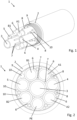
- FIG. 1 a charging cable 1 according to the present invention is shown, wherein in Figure 1 the charging cable 1 in a perspective view and in Figure 2 shown in a sectional view.
- the charging cable 1 for transmitting electrical energy has a sheathed cable 2 which encloses all components of the charging cable 1.
- a metal foil 9 is connected to an inner sheath surface of the sheathed cable 2, which can also be designed, for example, in the form of a metal foil or a metal-clad plastic film. The metal foil 9 therefore also encloses all components (except the sheathed cable 2) of the charging cable 1.
- the charging cable 1 also has five current conductor cables, namely a first current conductor cable A1, a second current conductor cable A2, a third current conductor cable B1 and a fourth current conductor cable B2, which in the illustrated embodiment are designed to transmit direct current, and a fifth current conductor cable PE designed as a protective conductor PE. All current conductor cables A1, A2, B1, B2, PE are each enclosed by an insulating sheath 6, so that the current conductor cables A1, A2, B1, B2, PE are not in electrical contact with their surroundings.
- a first current conductor pair consisting of the first current conductor cable A1 and the second current conductor cable A2 is assigned to a common first voltage potential.
- the first current conductor pair can, for example, be assigned to the positive pole in a charging cable 1 designed as a direct current charging cable 1.
- a second current conductor pair consisting of the third current conductor cable B1 and the fourth current conductor cable B2 is assigned to a common second voltage potential.
- the second current conductor pair can, for example, be assigned to the negative pole in a charging cable 1 designed as a direct current charging cable 1.
- the heat generated in the current conductor cables due to ohmic losses is transferred more effectively to the rest of the charging cable 1. Consequently, the power conductor cables A1, A2, B1, B2 have a lower temperature, so that larger charging currents can be transmitted with the power conductor cables A1, A2, B1, B2 without the power conductor cables A1, A2, B1, B2 and the charging cable 1 itself becoming excessively heated.
- the protective conductor PE is arranged between the second current conductor cable A2 and the fourth current conductor cable B2.
- the protective conductor PE can also be arranged between the first current conductor cable A1 and the third current conductor cable B1.
- the charging cable 1 further comprises three cooling lines 3, 4, 5 which are arranged within the sheathed line 2 and in each of which a cooling fluid channel is formed so that a cooling fluid can flow through the cooling lines 3, 4, 5.
- the first cooling line 3 is designed as a central cooling line 3.
- the central cooling line 3 is in direct contact with each of the power conductor cables A1, A2, B1, B2, PE.
- the second cooling line 4 is in direct contact with the central cooling line 3 as well as with the first power conductor cable A1 and the second power conductor cable A2.
- the third cooling line 5 is in direct contact with the central cooling line 3 as well as with the third power conductor cable B1 and the fourth power conductor cable B2. Due to the direct contact of the power cables A1, A2, B1, B2, PE with the cooling lines 3, 4, 5, the heat generated in the power cables A1, A2, B1, B2, PE is effectively dissipated by means of a cooling fluid flow within the cooling lines 3, 4, 5.
- the central cooling line 3 is in indirect contact with each of the power conductor cables A1, A2, B1, B2, PE by means of at least one strain relief cable 7 arranged between the central cooling line 3 and the respective power conductor cable A1, A2, B1, B2, PE.
- the respective strain relief cables 7 can be designed, for example, as aramid fiber cables 7.
- the central cooling line 3 is arranged centrally within the sheathed line 2 and that in the cross section of the charging cable 1 the central cooling line 3 is surrounded in a star shape by all the current conductor cables A1, A2, B1, B2, PE and by the second cooling line 4 and the third cooling line 5.
- the current conductor cables A1, A2, B1, B2, PE, the second cooling line 4 and the third cooling line 5 are thus arranged at an angular equidistant distance around the central cooling line 3 and are each in direct contact with the central cooling line 3.
- the charging cable 1 further comprises a plurality of signal lines 8, which are arranged between two current conductor cables A1, A2, B1, B2, PE that are directly adjacent to one another and in direct contact with one another.
- the signal lines 8 are also in direct contact with the current conductor cables A1, A2, B1, B2, PE E.
- some of the signal lines 8 are arranged between a power cable A1, A2, B1, B2, PE and the second cooling line 4 or the third cooling line 5 which are in direct contact with that power cable A1, A2, B1, B2, PE, and are in direct contact with the respective power cable A1, A2, B1, B2, PE and the second cooling line 4 or the third cooling line 5.
- the charging cable 1 according to the invention further comprises a plurality of filling strands 10, which are also referred to as filling cables 10.
- the filling strands 10 can be formed from a fiber material, for example from a cotton fiber fabric.
Landscapes
- Engineering & Computer Science (AREA)
- Power Engineering (AREA)
- Transportation (AREA)
- Mechanical Engineering (AREA)
- Electric Propulsion And Braking For Vehicles (AREA)
- Insulated Conductors (AREA)
- Charge And Discharge Circuits For Batteries Or The Like (AREA)
Description
- Die vorliegende Erfindung betrifft ein Ladekabel zur Übertragung elektrischer Energie, das insbesondere zur Übertragung elektrischer Energie beim Aufladen eines Elektrofahrzeugs verwendet wird. Ferner betrifft die vorliegende Erfindung einen Ladestecker zur Kopplung mit einer korrespondierenden Verbindungsvorrichtung und zur Übertragung elektrischer Energie. Weiterhin betrifft die vorliegende Erfindung eine Ladestation zur Abgabe elektrischer Energie an einen Empfänger elektrischer Energie.
- Aus dem Stand der Technik sind Ladekabel zur Übertragung elektrischer Energie bekannt, die zwei jeweils unterschiedlichen Spannungspotentialen zugeordnete Stromleitungskabel aufweisen, die von einer Mantelleitung umschlossen sind. Bei der Übertragung elektrischer Ströme über die Stromleitungskabel erwärmen sich diese aufgrund ohmscher Verluste innerhalb der Stromleitungskabel. Bei einer Erwärmung der Stromleitungskabel steigt wiederum der ohmsche Widerstand der Stromleitungskabel, so dass dann die Erwärmung der Stromleiterkabel beschleunigt vonstatten geht.
- Bei aus dem Stand der Technik bekannten Ladekabeln ist eine Übertragung von Wärme von dem Stromleitungskabel auf die weiteren im Ladekabel vorhandenen Strukturen nicht sehr effizient.
- Zur Reduzierung der erzeugten Wärme muss der ohmsche Widerstand des Stromleitungskabels reduziert werden. Hierzu ist es bekannt, die Leitungsquerschnitte von Stromleitungskabeln zu erhöhen. Diese Vorgehensweise stößt jedoch aus handhabungstechnischen Gründen an Grenzen, da ein entsprechendes Ladekabel, mit dem Ladeströme von 350 A bei Spannungen von bis zu 1000 V übertragbar sind, derart groß und schwer wäre, dass ein Bedienen eines Ladesteckers, in dem ein entsprechendes Ladekabel mündet, nur schwer möglich ist, da ein entsprechendes Ladekabel ein hohes Gewicht aufweisen würde.
- Aufgrund eines durch die Ladekabel fließenden Ladestroms heizen sich die Ladekabel unweigerlich aufgrund von ohmschen Stromwärmeverlusten auf. Das Aufheizen der Ladekabel ist jedoch auf eine Grenztemperaturerhöhung limitiert. So ist beispielsweise gemäß der Norm IEC 62196-3 die Grenztemperaturerhöhung auf 50K limitiert.
- Bei einer intermittierenden Aufladung eines Akkumulators sind hingegen höhere Ladeströme von 350 A und mehr über begrenzte Zeiträume notwendig, um den Akkumulator in einer gewünscht kurzen Zeit aufzuladen. Dies wiederum führt zu einer temporären Erhitzung der Ladekabel, die über der Grenztemperaturerhöhung liegt. Wie bereits oben erwähnt, kann der Leitungsquerschnitt der Ladekabel nicht beliebig vergrößert werden, da dies die Handhabe des mit den Ladekabeln verbundenen Ladesteckers erschweren würde.
- In diesem Zusammenhang ist beispielsweise aus der
DE 35 28 585 A1 eine Schrämleitung mit integriertem Wasserschlauch bekannt, wobei der Wasserschlauch im Zentrum der Leitung angeordnet ist. Drei Energieadern der Leitung sind in jeweils zwei Teiladern aufgeteilt, wobei diese sechs Teiladern zusammen mit kombinierten Steuer-/Überwachungsadern in symmetrischer Zuordnung einlagig auf den Wasserschlauch aufgeseilt sind. Dabei besteht jede Teilader aus einem Leiter, der Isolierung und einer äußeren Leitschicht. Jede Steuer-/Überwachungsader besteht aus einem Kernelement mit einem Tragfaden, einer Kunststoffumhüllung und einem konzentrisch aufgebrachten Steuerleiter, einer Isolierung und einem darauf aufgebrachten konzentrischen Überwachungsleitermit einer darüber angeordneten extrudierten äußeren Leitschicht. Auf den Verseilverband sind unter Zwischenlage einer Folienbespinnung der Innenmantel und der Außenmantel aufgebracht. In den Außenmantel ist ein metallisches Geflecht aus einer Mischlitze aus Kupfer- und Stahldrähten eingebettet, das zugleich den Schutzleiter der Leitung bildet. - Das Dokument Anonymous: "Leitungsquerschnitt paralleler Adern - Mikrocontroller.net", 21. Juni 2007 (2007-06-21), XP055391912, betrifft allgemeine Lehren zu Leitungsquerschnitten paralleler Adern.
- Dokument
WO 2015/060294 A1 betrifft ein Ladesteckverbinder mit einem stromversorgungsseitigen Anschluss, der mit der Stromversorgungsseite verbunden ist, einem Innengehäuse, das den stromversorgungsseitigen Anschluss aufnimmt, einem Zwischenanschluss, der einen Stromversorgungsanschlussabschnitt, der elektrisch mit dem stromversorgungsseitigen Anschluss verbunden und von diesem getrennt werden kann, und einem Einlassanschlussabschnitt, der elektrisch mit einem einlassseitigen Anschluss, der mit der Fahrzeugeinlassseite verbunden ist, verbunden und von diesem getrennt werden kann. Ein Kassettengehäuse, das den Zwischenanschluss aufnimmt und an das Innengehäuse montiert ist, kann in den Fahrzeugeinlass eingebaut werden. -
US 2015/217654 A1 betrifft ein Ladesystem für ein elektrisches Fahrzeug umfassend: eine Stromversorgung; ein Kabel mit einem ersten und einem zweiten Ende, wobei das erste Ende an der Stromversorgung befestigt ist, wobei das Kabel einen Ladeleiter und eine Kühlleitung umfasst, die sich jeweils von dem ersten Ende zu dem zweiten Ende erstrecken; und einen Verbinder, der an dem zweiten Ende des Kabels befestigt ist, wobei der Verbinder einen Formfaktor aufweist, der einem Ladeanschluss des elektrischen Fahrzeugs entspricht; wobei die Kühlleitung angepasst ist, um ein Fluid zu transportieren, das den Ladeleiter kühlt. - Der vorliegenden Erfindung liegt die Aufgabe zugrunde, ein Ladekabel bereitzustellen, das erhöhte Ladeströme bei einer begrenzten Aufheizung ermöglicht, folglich also eine erhöhte Stromtragfähigkeit aufweist.
- Diese Aufgabe wird durch ein Ladekabel mit den Merkmalen des Anspruchs 1 gelöst. Vorteilhafte Ausführungsformen sind in den von Anspruch 1 abhängigen Ansprüchen beschrieben.
- Ferner liegt der vorliegenden Erfindung die Aufgabe zugrunde, ein Ladesystem bereitzustellen, mittels dem erhöhte Ladeströme übertragbar sind, ohne dass sich der Ladestecker übermäßig erhitzt.
- Die Erfindung ist durch die Ansprüche definiert.
- Diese Aufgabe wird durch ein Ladesystem mit den Merkmalen des Anspruchs 10 gelöst.
- Letztendlich liegt der vorliegenden Erfindung auch die Aufgabe zugrunde, eine Ladestation zur Abgabe elektrischer Energie an einen Empfänger elektrischer Energie bereitzustellen, mittels der erhöhte Spitzenladeströme übertragbar sind. Diese Aufgabe wird durch eine Ladestation mit den Merkmalen des Anspruchs 11 gelöst.
- Im Genaueren wird die der vorliegenden Erfindung zugrundeliegende Aufgabe durch ein Ladekabel zur Übertragung elektrischer Energie mit einer Mantelleitung gelöst, wobei das Ladekabel die folgenden Merkmale aufweist:
- innerhalb der Mantelleitung sind zumindest vier Stromleiterkabel angeordnet;
- ein erstes Stromleiterkabel und ein zweites Stromleiterkabel sind gemeinsam einem ersten Spannungspotential zugeordnet;
- ein drittes Stromleiterkabel und ein viertes Stromleiterkabel sind gemeinsam einem zweiten Spannungspotential zugeordnet;
- die ersten und zweiten Stromleiterkabel sowie die dritten und vierten Stromleiterkabel an den Enden des Ladekabels entsprechend verbunden sind;
- innerhalb der Mantelleitung ist zusätzlich ein fünftes Stromleiterkabel angeordnet, das als Schutzleiterkabel ausgebildet ist;
- das Ladekabel weist zumindest eine Kühlleitung auf, die innerhalb der Mantelleitung angeordnet und von einem Kühlfluid durchströmbar ist;
- die Kühlleitung steht mit jedem Stromleiterkabel in direktem Kontakt;
- die Kühlleitung ist als Zentralkühlleitung zentral innerhalb der Mantelleitung angeordnet;
- im Querschnitt des Ladekabels ist die Zentralkühlleitung von sämtlichen Stromleiterkabel sternförmig umgeben;
- die Zentralkühlleitung steht mit jedem Stromleiterkabel in direktem Kontakt;
- das Ladekabel weist zusätzlich zu der Zentralkühlleitung eine zweite Kühlleitung und eine dritte Kühlleitung auf, die jeweils von einem Kühlfluid durchströmbar sind; und
- im Querschnitt des Ladekabels sind die zweite Kühlleitung und die dritte Kühlleitung sternförmig um die Zentralkühlleitung angeordnet.
- Die Mantelleitung kann alternativ auch als Kabelmantel bezeichnet werden.
- Durch Bereitstellen von vier Stromleiterkabeln, wobei jeweils zwei Stromleiterkabel einem gemeinsamen Spannungspotential zugeordnet sind, vergrößert sich die Oberfläche der Stromleitungspaare, die jeweils einem Spannungspotential zugeordnet sind. Dabei bilden das erste Stromleiterkabel und das zweite Stromleiterkabel ein erstes Stromleiterpaar, das einem gemeinsamen Spannungspotential zugeordnet ist, beispielsweise dem Pluspol bei einem als Gleichspannungsladekabel ausgebildeten Ladekabel. Das dritte Stromleitungskabel und das vierte Stromleitungskabel bilden ein zweites Stromleiterpaar, das einem gemeinsamen Spannungspotential zugeordnet ist, beispielsweise dem Minuspol bei einem als Gleichspannungsladekabel ausgebildeten Ladekabel. Durch die Vergrößerung der Oberfläche der stromführenden Kabel wird die in den Stromleiterkabeln durch ohmsche Verluste erzeugte Wärme verbessert auf den Rest des Ladekabels übertragen. Folglich weisen die Stromleiterkabel eine niedrigere Temperatur auf, so dass mit den Stromleiterkabeln größere Ladeströme übertragen werden können, ohne dass die Stromleiterkabel und das Ladekabel selber übermäßig erhitzt werden. Folglich ist es möglich, mit dem erfindungsgemäßen Ladekabel erhöhte Ladeströme zu übertragen, ohne die Leitungsquerschnitte der Stromleiterkabel zu vergrößern. Daher wird die Handhabbarkeit des Ladekabels und beispielsweise eines mit dem Ladekabel gekoppelten Ladesteckers nicht verschlechtert, obwohl größere Ladeströme mittels der Ladekabel übertragbar sind. Weiterhin wird eine übermäßige Erhitzung der Stromleiterkabel verhindert.
- Durch Anordnen einer Kühlleitung, die von einem Kühlfluid durchströmbar ist, wird das Ladekabel nochmals verbessert gekühlt. Die in den Stromleiterkabeln durch ohmsche Verluste erzeugte Wärme wird auf die Kühlleitung und somit auf das die Kühlleitung durchströmende Kühlfluid übertragen, so dass die Temperatur des gesamten Ladekabels und insbesondere die Temperatur der Stromleiterkabel besonders effektiv reduziert wird. Daher können mit einem entsprechend ausgebildeten Ladekabel nochmals größere Ladeströme übertragen werden, ohne dass die Querschnitte der Stromleiterkabel vergrößert werden müssen. Hierdurch bleibt die Handhabbarkeit des Ladekabels und eines mit dem Ladekabel verbundenen Ladesteckers erhalten.
- Durch eine entsprechende Ausbildung des Ladekabels ist eine besonders effektive Kühlung ermöglicht.
- Bei dem entsprechend ausgebildeten Ladekabel kann die in den Stromleiterkabeln erzeugte Wärme nochmals verbessert auf die Kühlleitung übertragen werden, so dass sich mit dem entsprechend ausgebildeten Ladekabel erhöhte Ladeströme übertragen lassen.
- Durch Bereitstellen weiterer Kühlleitungen im Ladekabel kann dieses verbessert gekühlt werden. Insbesondere durch die sternförmige Anordnung der zweiten Kühlleitung und der dritten Kühlleitung um die Zentralkühlleitung können die Stromleiterkabel an die Kühlleitungen aufgrund der erhöhten Kontaktfläche verbessert Wärme abgeben.
- Vorzugsweise sind das erste Stromleiterkabel und das zweite Stromleiterkabel miteinander galvanisch verbunden. Diese galvanische Verbindung kann vorzugsweise an den Enden des Ladekabels realisiert sein. Ferner sind vorzugsweise das dritte Stromleiterkabel und das vierte Stromleiterkabel miteinander galvanisch verbunden. Weiter vorzugsweise weisen die Stromleiterkabel einen kreisrunden Querschnitt auf. Weiter vorzugsweise sind die Durchmesser der Stromleiterkabel identisch.
- Die Stromleiterkabel sind vorzugsweise jeweils von einem Isolationsmantel umschlossen. Das Ladekabel ist insbesondere für die Kopplung mit einem Ladestecker zur Aufladung eines Elektrofahrzeugs ausgebildet.
- Gemäß einer vorteilhaften Ausgestaltung des Ladekabels ist an einer Innenmantelfläche der Mantelleitung eine Metallschicht, beispielsweise in Form einer Metallfolie oder einer metallkaschierten Kunststofffolie vorgesehen. Weiter vorzugsweise steht die Metallschicht/Metallfolie/metallkaschierte Kunststofffolie mit der Innenmantelfläche der Mantelleitung in direktem Kontakt.
- Das entsprechend ausgebildete Ladekabel weist eine homogenere Wärmeverteilung insbesondere an einer Außenfläche des Ladekabels.
- Weiter vorzugsweise ist das Ladekabel derart ausgebildet, dass das fünfte Stromleiterkabel zwischen dem zweiten Stromleiterkabel und dem vierten Stromleiterkabel oder zwischen dem ersten Stromleiterkabel und dem dritten Stromleiterkabel angeordnet ist.
- Dabei steht das fünfte Stromleiterkabel, also das Schutzeiterkabel vorzugsweise mit dem zweiten Stromleiterkabel und dem vierten Stromleiterkabel oder mit dem ersten Stromleiterkabel und dem dritten Stromleiterkabel in direktem Kontakt. Durch eine entsprechende Ausbildung des Ladekabels kann in den ersten bis vierten Stromleiterkabeln erzeugte Wärme auf das Schutzleiterkabel übertragen werden, so dass die Wärme innerhalb des Ladekabels verbessert verteilt wird, wodurch die Temperaturen der ersten bis vierten Stromleitungskabel reduziert wird. Daher können mittels der ersten bis vierten Stromleiterkabeln erhöhte Ladeströme übertragen werden, ohne das die Stromleiterkabel und das Ladekabel selbst übermäßig erhitzen.
- Selbstverständlich können innerhalb des Ladekabels auch zwei und mehr Kühlleitungen angeordnet sein, die alle innerhalb der Mantelleitung angeordnet sind.
- Als Kühlfluid kann beispielsweise Wasser verwendet werden. Ferner können als Kühlfluid Ketone, insbesondere fluorisierte Ketone verwendet werden. Ketone weisen den Vorteil auf, dass diese nicht elektrisch leitfähig sind.
- Die Kühlleitung, die auch als Zentralkühlleitung bezeichnet wird, weist vorzugsweise einen größeren Durchmesser als die jeweiligen Stromleiterkabel auf.
- Weiter vorzugsweise steht die Kühlleitung mit jedem Stromleiterkabel mittels zumindest eines zwischen der Kühlleitung und dem jeweiligen Stromleiterkabel angeordneten Zugentlastungskabels in mittelbarem Kontakt.
- Durch Bereitstellen der Zugentlastungskabel zwischen den Stromleiterkabeln und der Kühlleitung stehen die Stromleiterkabel zusätzlich zu einem möglichen unmittelbaren Kontakt auch mittelbar über die jeweiligen Zugentlastungkabel mit der Kühlleitung in Kontakt, so dass die Wärme in den Stromleitungskabeln nochmals verbessert auf die Kühlleitung übertragen werden kann. Die Zugentlastungskabel sind dabei vorzugsweise als Aramidfaserkabel ausgebildet.
- Vorzugsweise weisen die zweite Kühlleitung und die Dritte Kühlleitung jeweils einen kreisförmigen Querschnitt auf. Weiter vorzugsweise weisen die zweite Kühlleitung und die dritte Kühlleitung einen gleichen Durchmesser wie die Stromleiterkabel auf.
- Weiter vorzugsweise ist das Ladekabel derart ausgebildet, dass die Zentralkühlleitung mit der zweiten Kühlleitung und der dritten Kühlleitung in direktem Kontakt steht, und wobei die Zentralkühlleitung ferner mit der zweiten Kühlleitung und der dritten Kühlleitung mittels zumindest jeweils einem zwischen der Zentralkühlleitung und der zweiten Kühlleitung und zwischen der Zentralkühlleitung und der dritten Kühlleitung angeordneten Zugentlastungskabel in mittelbarem Kontakt steht.
- Bei dem entsprechend ausgebildeten Ladekabel kann die in den Stromleiterkabeln erzeugte Wärme nochmals verbessert auf die Kühlleitung übertragen werden, so dass sich mit dem entsprechend ausgebildeten Ladekabel erhöhte Ladeströme übertragen lassen.
- Vorteilhafterweise ist das Ladekabel dabei derart ausgebildet, dass das Ladekabel zusätzlich zu der Zentralkühlleitung eine zweite Kühlleitung und eine dritte Kühlleitung aufweist, die jeweils von einem Kühlfluid durchströmbar sind, wobei im Querschnitt des Ladekabels die zweite Kühlleitung und die dritte Kühlleitung sternförmig um die Zentralkühlleitung angeordnet sind.
- Durch Bereitstellen weiterer Kühlleitungen im Ladekabel kann dieses verbessert gekühlt werden. Insbesondere durch die sternförmige Anordnung der zweiten Kühlleitung und der dritten Kühlleitung um die Zentralkühlleitung können die Stromleiterkabel an die Kühlleitungen aufgrund der erhöhten Kontaktfläche verbessert Wärme abgeben.
- Vorzugsweise weisen die zweite Kühlleitung und die Dritte Kühlleitung jeweils einen kreisförmigen Querschnitt auf. Weiter vorzugsweise weisen die zweite Kühlleitung und die dritte Kühlleitung einen gleichen Durchmesser wie die Stromleiterkabel auf.
- Weiter vorzugsweise ist das Ladekabel derart ausgebildet, dass die Zentralkühlleitung mit der zweiten Kühlleitung und der dritten Kühlleitung in direktem Kontakt steht, und wobei die Zentralkühlleitung ferner mit der zweiten Kühlleitung und der dritten Kühlleitung mittels zumindest jeweils einem zwischen der Zentralkühlleitung und der zweiten Kühlleitung und zwischen der Zentralkühlleitung und der dritten Kühlleitung angeordneten Zugentlastungskabel in mittelbarem Kontakt steht.
- Gemäß einer weiteren vorteilhaften Ausgestaltung ist das Ladekabel derart ausgebildet, dass die zweite Kühlleitung zwischen dem ersten Stromleiterkabel und dem zweiten Stromleiterkabel oder zwischen dem zweiten Stromleiterkabel und dem fünften Stromleiterkabel angeordnet ist steht mit diesen jeweils in direktem Kontakt steht, wobei die dritte Kühlleitung zwischen dem dritten Stromleiterkabel und dem vierten Stromleiterkabel oder zwischen dem vierten Stromleiterkabel und dem fünften Stromleiterkabel angeordnet ist und mit diesen jeweils in direktem Kontakt steht.
- Eine entsprechende Ausbildung des Ladekabels ermöglicht einen nochmals verbesserten Wärmeübertrag von den Stromleiterkabeln auf die Kühlleitungen, so dass die Stromleiterkabel eine verminderte Temperatur aufweisen, wodurch mittels der Stromleiterkabel erhöhte Ladeströme übertragbar sind.
- Vorteilhafterweise ist das Ladekabel derart ausgebildet, dass im Querschnitt des Ladekabels die Stromleiterkabel, die zweite Kühlleitung und die dritte Kühlleitung winkeläquidistant um die Zentralkühlleitung herum angeordnet sind und jeweils mit der Zentralkühlleitung in direktem Kontakt stehen.
- Aufgrund des symmetrischen Aufbaus des entsprechend ausgebildeten Ladekabels bietet dieses eine verbesserte Wärmeübertragung von den Stromleiterkabeln auf die übrigen Strukturen und die übrigen Bauteile des Ladekabels, so dass diese eine gleichmäßigere Temperatur aufweist.
- Weiter vorzugsweise ist das Ladekabel derart ausgebildet, dass zwischen zwei zueinander direkt benachbarten und miteinander in direktem Kontakt stehenden Stromleiterkabeln eine Signalleitung angeordnet ist, die mit den miteinander in direktem Kontakt stehenden Stromleiterkabel ebenfalls in direktem Kontakt steht.
- Auch durch den direkten Kontakt eines Stromleiterkabels mit einer Signalleitung wird Wärme von dem Stromleiterkabel auf das Signalkabel übertragen, wodurch sich die Temperatur der Stromleiterkabel vermindert.
- Gemäß einer weiteren vorteilhaften Ausgestaltung ist das Ladekabel derart ausgebildet, dass zwischen einem Stromleiterkabel und der zweiten Kühlleitung oder der dritten Kühlleitung, die mit dem Stromleiterkabel in direktem Kontakt steht, zumindest eine Signalleitung angeordnet ist, die mit dem Stromleiterkabel und mit der zweiten Kühlleitung oder der dritten Kühlleitung in direktem Kontakt steht.
- Folglich stehen die Stromleiterkabel zusätzlich über den unmittelbaren Kontakt mit den Kühlleitungen mit diesen mittelbar über die Signalleitung in Kontakt, so dass die in den Stromleitungskabeln erzeugte Wärme verbessert auf die Kühlleitungen übertragen werden kann, wodurch die Temperatur der Stromleitungskabel nochmals effektiver reduziert wird.
- Vorzugsweise sind die Stromleiterkabel und/oder die Kühlleitungen und/oder die Zugentlastungskabel sternförmig um die Zentralkühlleitung angeordnet.
- Die der vorliegenden Erfindung zugrundeliegende Aufgabe wird auch durch ein Ladesystem, umfassend das erfindungsgemäße Ladekabel und einen Ladestecker zur Kopplung mit einer korrespondierenden Verbindungsvorrichtung und zur Übertragung elektrischer Energie gelöst, der dadurch gekennzeichnet ist, dass der Ladestecker zumindest zwei in einem Ladesteckergehäuse angeordnetes Leistungskontakte aufweist, die über eine Kontaktseite des Ladesteckergehäuses zugänglich sind, wobei ein erster Leistungskontakt galvanisch mit dem ersten Stromleiterkabel und dem zweiten Stromleiterkabel des Ladekabels verbunden ist, und wobei ein zweiter Leistungskontakt galvanisch mit dem dritten Stromleiterkabel und dem vierten Stromleiterkabel des Ladekabels verbunden ist.
- Ferner wird die der vorliegenden Erfindung zugrundeliegende Aufgabe durch eine Ladestation zur Abgabe elektrischer Energie an einen Empfänger elektrischer Energie gelöst, die ein oben beschriebenes Ladesystem aufweist.
- Weitere Vorteile, Einzelheiten und Merkmale der Erfindung ergeben sich nachfolgend aus den erläuterten Ausführungsbeispielen. Dabei zeigen im Einzelnen:
- Figur 1:
- eine perspektivische Darstellung eines erfindungsgemäßen Ladekabels der vorliegenden Erfindung; und
- Figur 2:
- eine Schnittdarstellung des in
Figur 1 dargestellten Ladekabels. - In der nun folgenden Beschreibung bezeichnen gleiche Bezugszeichen gleiche Bauteile beziehungsweise gleiche Merkmale, so dass eine in Bezug auf eine Figur durchgeführte Beschreibung bezüglich eines Bauteils auch für die anderen Figuren gilt, so dass eine wiederholende Beschreibung vermieden wird. Ferner sind einzelne Merkmale, die in Zusammenhang mit einer Ausführungsform beschrieben wurden, auch separat in andere Ausführungsformen verwendbar.
- In den
Figuren 1 und 2 ist ein erfindungsgemäßes Ladekabel 1 gemäß der vorliegenden Erfindung dargestellt, wobei inFigur 1 das Ladekabel 1 in einer perspektivischen Darstellung und inFigur 2 in einer Schnittdarstellung gezeigt ist. - Das Ladekabel 1 zur Übertragung elektrischer Energie weist eine Mantelleitung 2 auf, die sämtliche Komponenten des Ladekabels 1 umschließt. An einer Mantelinnenfläche der Mantelleitung 2 schließt sich eine Metallfolie 9 an, die auch beispielsweise in Form einer Metallfolie oder einer metallkaschierten Kunststofffolie ausgebildet sein kann. Die Metallfolie 9 umschließt folglich auch sämtliche Komponenten (außer die Mantelleitung 2) des Ladekabels 1. Das Ladekabel 1 weist ferner fünf Stromleiterkabel, nämlich ein erstes Stromleiterkabel A1, ein zweites Stromleiterkabel A2, ein drittes Stromleiterkabel B1 und ein viertes Stromleiterkabel B2, die in dem dargestellten Ausführungsbeispiel zu Übertragung von Gleichstrom ausgebildet sind, und ein als Schutzleiter PE ausgebildetes fünftes Stromleiterkabel PE auf. Sämtliche Stromleiterkabel A1, A2, B1, B2, PE sind jeweils von einem Isolationsmantel 6 umschlossen, sodass die Stromleiterkabel A1, A2, B1, B2, PE mit deren Umgebung nicht in elektrischen Kontakt stehen.
- Ein erstes Stromleiterpaar bestehend aus dem ersten Stromleiterkabel A1 und dem zweite Stromleiterkabel A2 ist dabei einem gemeinsamen ersten Spannungspotential zugeordnet. Das erste Stromleiterpaar kann beispielsweise dem Pluspol bei einem als Gleichspannungsladekabel 1 ausgebildeten Ladekabel 1 zugeordnet sein. Ein zweites Stromleiterpaar bestehend aus dem dritten Stromleiterkabel B1 und dem vierten Stromleiterkabel B2 ist einem gemeinsamen zweiten Spannungspotential zugeordnet. Das zweite Stromleiterpaar kann beispielsweise dem Minuspol bei einem als Gleichspannungsladekabel 1 ausgebildeten Ladekabel 1 zugeordnet sein. Durch die Vergrößerung der Oberfläche, im Genaueren der Mantelflächen der Stromleiterkabel A1, A2, B1, B2 wird die in den Stromleiterkabeln durch ohmsche Verluste erzeugte Wärme verbessert auf den Rest des Ladekabels 1 übertragen. Folglich weisen die Stromleiterkabel A1, A2, B1, B2 eine niedrigere Temperatur auf, so dass mit den Stromleiterkabeln A1, A2, B1, B2 größere Ladeströme übertragen werden können, ohne dass die Stromleiterkabel A1, A2, B1, B2 und das Ladekabel 1 selber übermäßig erhitzt werden.
- Der Schutzleiter PE ist zwischen dem zweiten Stromleiterkabel A2 und dem vierten Stromleiterkabel B2 angeordnet. Alternativ kann der Schutzleiter PE auch zwischen dem ersten Stromleiterkabel A1 und dem dritten Stromleiterkabel B1 angeordnet sein.
- Aus den
Figuren 1 und 2 ist ersichtlich, dass das Ladekabel 1 ferner drei Kühlleitungen 3, 4, 5 aufweist, die innerhalb der Mantelleitung 2 angeordnet sind, und in denen jeweils ein Kühlfluidkanal gebildet ist, sodass die Kühlleitungen 3, 4, 5 von einem Kühlfluid durchströmbar sind. Dabei ist die erste Kühlleitung 3 als Zentralkühlleitung 3 ausgebildet. Die Zentralkühlleitung 3 steht mit jedem der Stromleiterkabel A1, A2, B1, B2, PE in direktem Kontakt. Die zweite Kühlleitung 4 steht sowohl mit der Zentralkühlleitung 3 als auch mit dem ersten Stromleiterkabel A1 und dem zweiten Stromleiterkabel A2 in direktem Kontakt. Die dritte Kühlleitung 5 steht sowohl mit der Zentralkühlleitung 3 als auch mit dem dritten Stromleiterkabel B1 und dem vierten Stromleiterkabel B2 in direktem Kontakt. Aufgrund des direkten Kontakts der Stromleiterkabel A1, A2, B1, B2, PE mit den Kühlleitungen 3, 4, 5 wird die in den Stromleiterkabeln A1, A2, B1, B2, PE erzeugte Wärme somit mittels eines Kühlfluidstroms innerhalb der Kühlleitungen 3, 4, 5 effektiv abtransportiert. - Aus den Figuren ist ferner ersichtlich, dass die Zentralkühlleitung 3 mit jedem der Stromleiterkabel A1, A2, B1, B2, PE mittels zumindest einem zwischen der Zentralkühlleitung 3 und dem jeweiligen Stromleiterkabel A1, A2, B1, B2, PE angeordneten Zugentlastungskabel 7 in mittelbarem Kontakt. Die jeweiligen Zugentlastungkabel 7 können beispielsweise als Aramidfaserkabel 7 ausgebildet sein. Durch Bereitstellen der Zugentlastungskabel 7 zwischen den Stromleiterkabeln A1, A2, B1, B2, PE und der Zentralkühlleitung 3 stehen die Stromleiterkabel A1, A2, B1, B2, PE zusätzlich zu dem unmittelbaren Kontakt auch mittelbar über die jeweiligen Zugentlastungkabel 7 mit der Zentralkühlleitung 3 in Kontakt, so dass die Wärme in den Stromleitungskabeln A1, A2, B1, B2, PE nochmals verbessert auf die Zentralkühlleitung 3 übertragen werden kann.
- Aus den Figuren ist ferner ersichtlich, dass die Zentralkühlleitung 3 zentral innerhalb der Mantelleitung 2 angeordnet ist und im Querschnitt des Ladekabels 1 die Zentralkühlleitung 3 von sämtlichen Stromleiterkabeln A1, A2, B1, B2, PE und von der zweiten Kühlleitung 4 und der dritten Kühlleitung 5 sternförmig umgeben ist. Im Querschnitt des Ladekabels 1 sind somit die Stromleiterkabel A1, A2, B1, B2, PE, die zweite Kühlleitung 4 und die dritte Kühlleitung 5 winkeläquidistant um die Zentralkühlleitung 3 herum angeordnet und stehen mit der Zentralkühlleitung 3 jeweils in direktem Kontakt.
- Das erfindungsgemäße Ladekabel 1 umfasst ferner mehrere Signalleitungen 8, die zwischen jeweils zwei zueinander direkt benachbarten und miteinander in direktem Kontakt stehenden Stromleiterkabeln A1, A2, B1, B2, PE angeordnet sind. Die Signalleitungen 8 stehen dabei jeweils mit den Stromleiterkabeln A1, A2, B1, B2, PE E ebenfalls in direktem Kontakt.
- Ferner sind einige der Signalleitungen 8 zwischen einem Stromleiterkabel A1, A2, B1, B2, PE und der zweiten Kühlleitung 4 oder der dritten Kühlleitung 5, die mit demjenigen Stromleiterkabel A1, A2, B1, B2, PE in direkten Kontakt stehen, angeordnet, und stehen mit dem jeweiligen Stromleiterkabel A1, A2, B1, B2, PE und der zweiten Kühlleitung 4 oder der dritten Kühlleitung 5 in direktem Kontakt.
- Das erfindungsgemäße Ladekabel 1 weist ferner mehrere Füllstränge 10 auf, die auch als Füllkabel 10 bezeichnet werden. Die Füllstränge 10 können aus einem Fasermaterial, beispielsweise aus einem Baumwollfasergewebe gebildet sein.
-
- 1
- Ladekabel
- 2
- Mantelleitung / Kabelmantel
- 3
- (erste) Kühlleitung / Zentralkühlleitung
- 4
- zweite Kühlleitung
- 5
- dritte Kühlleitung
- 6
- Isolationsmantel (der jeweiligen Stromleiterkabel)
- 7
- Zugentlastungskabel / Aramidfaserkabel
- 8
- Signalleitung
- 9
- Metallfolie
- 10
- Füllkabel
- A1
- erstes Stromleiterkabel
- A2
- zweites Stromleiterkabel
- B1
- drittes Stromleiterkabel
- B2
- viertes Stromleiterkabel
- PE
- Schutzleiter / fünftes Stromleiterkabel
Claims (11)
- Ladekabel (1) zur Übertragung elektrischer Energie mit einer Mantelleitung (2), wobei das Ladekabel (1) die folgenden Merkmale aufweist:- innerhalb der Mantelleitung (2) sind zumindest vier Stromleiterkabel (A1, A2, B1, B2, PE) angeordnet;- ein erstes Stromleiterkabel (A1) und ein zweites Stromleiterkabel (A2) sind gemeinsam einem ersten Spannungspotential zugeordnet;- ein drittes Stromleiterkabel (B1) und ein viertes Stromleiterkabel (B2) sind gemeinsam einem zweiten Spannungspotential zugeordnet;- die ersten und zweiten Stromleiterkabel (A1, A2) sowie die dritten und vierten Stromleiterkabel (B1, B2) an den Enden des Ladekabels entsprechend verbunden sind;- innerhalb der Mantelleitung (2) ist zusätzlich ein fünftes Stromleiterkabel (PE) angeordnet, das als Schutzleiterkabel (PE) ausgebildet ist;- das Ladekabel (1) weist zumindest eine Kühlleitung (3, 4, 5) auf, die innerhalb der Mantelleitung (2) angeordnet und von einem Kühlfluid durchströmbar ist;- die Kühlleitung (3) steht mit jedem Stromleiterkabel (A1, A2, B1, B2, PE) in direktem Kontakt;- die Kühlleitung (3) ist als Zentralkühlleitung (3) zentral innerhalb der Mantelleitung (2) angeordnet;- im Querschnitt des Ladekabels (1) ist die Zentralkühlleitung (3) von sämtlichen Stromleiterkabeln (A1, A2, B1, B2, PE) sternförmig umgeben; und- die Zentralkühlleitung (3) steht mit jedem Stromleiterkabel (A1, A2, B1, B2, PE) in direktem Kontakt;wobei das Ladekabel (1) gekennzeichnet ist durch die folgenden Merkmale:- das Ladekabel (1) weist zusätzlich zu der Zentralkühlleitung (3) eine zweite Kühlleitung (4) und eine dritte Kühlleitung (5) auf, die jeweils von einem Kühlfluid durchströmbar sind; und- im Querschnitt des Ladekabels (1) sind die zweite Kühlleitung (4) und die dritte Kühlleitung (5) sternförmig um die Zentralkühlleitung (3) angeordnet.
- Ladekabel (1) nach Anspruch 1, dadurch gekennzeichnet, dass an einer Innenmantelfläche der Mantelleitung (2) eine Metallfolie (9) angeordnet ist.
- Ladekabel (1) nach Anspruch 1 dadurch gekennzeichnet, dass das fünfte Stromleiterkabel (PE) zwischen dem zweiten Stromleiterkabel (A2) und dem vierten Stromleiterkabel (B2) oder zwischen dem ersten Stromleiterkabel (A1) und dem dritten Stromleiterkabel (B1) angeordnet ist.
- Ladekabel (1) nach zumindest einem der Ansprüche 1 oder 3, dadurch gekennzeichnet, dass die Kühlleitung (3) mit jedem Stromleiterkabel (A1, A2, B1 B2, PE) mittels zumindest einem zwischen der Kühlleitung (3) und dem jeweiligen Stromleiterkabel (A1, A2, B1, B2, PE) angeordneten Zugentlastungskabel (7) in mittelbarem Kontakt steht.
- Ladekabel (1) nach zumindest einem der vorhergehenden Ansprüche, gekennzeichnet durch die folgenden Merkmale:- die Zentralkühlleitung (3) steht mit der zweiten Kühlleitung (4) und der dritten Kühlleitung (5) in direktem Kontakt; und- die Zentralkühlleitung (3) steht ferner mit der zweiten Kühlleitung (4) und der dritten Kühlleitung (5) mittels zumindest jeweils einem zwischen der Zentralkühlleitung (3) und der zweiten Kühlleitung (4) und zwischen der Zentralkühlleitung (3) und der dritten Kühlleitung (5) angeordneten Zugentlastungskabel (7) in mittelbarem Kontakt.
- Ladekabel (1) nach zumindest einem der vorhergehenden Ansprüche, gekennzeichnet durch die folgenden Merkmale:- die zweite Kühlleitung (4) ist zwischen dem ersten Stromleiterkabel (A1) und dem zweiten Stromleiterkabel (A2) oder zwischen dem zweiten Stromleiterkabel (A2) und dem fünften Stromleiterkabel (PE) angeordnet und steht mit diesen jeweils in direktem Kontakt; und- die dritte Kühlleitung (5) ist zwischen dem dritten Stromleiterkabel (B1) und dem vierten Stromleiterkabel (B2) oder zwischen dem vierten Stromleiterkabel (B2) und dem fünften Stromleiterkabel (PE) angeordnet und steht mit diesen jeweils in direktem Kontakt.
- Ladekabel (1) nach zumindest einem der vorhergehenden Ansprüche, dadurch gekennzeichnet, dass im Querschnitt des Ladekabels (1) die Stromleiterkabel (A1, A2, B1, B2, PE), die zweite Kühlleitung (4) und die dritte Kühlleitung (5) winkeläquidistant um die Zentralkühlleitung (3) herum angeordnet sind und jeweils mit der Zentralkühlleitung (3) in direktem Kontakt stehen.
- Ladekabel (1) nach zumindest einem der vorhergehenden Ansprüche, dadurch gekennzeichnet, dass zwischen zwei zueinander direkt benachbarten und miteinander in direktem Kontakt stehenden Stromleiterkabeln (A1, A2, B1, B2, PE) eine Signalleitung (8) angeordnet ist, die mit den miteinander in direktem Kontakt stehenden Stromleiterkabeln (A1, A2, B1, B2, PE) ebenfalls in direktem Kontakt steht.
- Ladekabel (1) nach zumindest einem der vorhergehenden Ansprüche, dadurch gekennzeichnet, dass zwischen einem Stromleiterkabel (A1, A2, B1, B2, PE) und der zweiten Kühlleitung (4) oder der dritten Kühlleitung (5), die mit dem Stromleiterkabel (A1, A2, B1, B2, PE) in direktem Kontakt steht, zumindest eine Signalleitung (8) angeordnet ist, die mit dem Stromleiterkabel (A1, A2, B1, B2, PE) und mit der zweiten Kühlleitung (4) oder der dritten Kühlleitung (5) in direktem Kontakt steht.
- Ladesystem, umfassend- Ladekabel (1) nach einem der Ansprüche 1-9, und- Ladestecker zur Kopplung mit einer korrespondierenden Verbindungsvorrichtung und zur Übertragung elektrischer Energie, der Ladestecker gekennzeichnet durch die folgenden Merkmale:- der Ladestecker weist zumindest zwei in einem Ladesteckergehäuse angeordnete Leistungskontakte auf, die über eine Kontaktseite des Ladesteckergehäuses zugänglich sind;- ein erster Leistungskontakt ist galvanisch mit dem ersten Stromleiterkabel (A1) und dem zweiten Stromleiterkabel (A2) des Ladekabels (1) verbunden; und- ein zweiter Leistungskontakt ist galvanisch mit dem dritten Stromleiterkabel (B1) und dem vierten Stromleiterkabel (B2) des Ladekabels (1) verbunden.
- Ladestation zur Abgabe elektrischer Energie an einen Empfänger elektrischer Energie, dadurch gekennzeichnet, dass die Ladestation eine Ladesystem nach Anspruch 10 aufweist.
Applications Claiming Priority (2)
| Application Number | Priority Date | Filing Date | Title |
|---|---|---|---|
| DE102016209607.9A DE102016209607A1 (de) | 2016-06-01 | 2016-06-01 | Ladekabel zur Übertragung elektrischer Energie, Ladestecker und Ladestation zur Abgabe elektrischer Energie an einen Empfänger elektrischer Energie |
| PCT/EP2017/061716 WO2017207266A1 (de) | 2016-06-01 | 2017-05-16 | Ladekabel zur übertragung elektrischer energie, ladestecker und ladestation zur abgabe elektrischer energie an einen empfänger elektrischer energie |
Publications (2)
| Publication Number | Publication Date |
|---|---|
| EP3465699A1 EP3465699A1 (de) | 2019-04-10 |
| EP3465699B1 true EP3465699B1 (de) | 2024-08-14 |
Family
ID=58745216
Family Applications (1)
| Application Number | Title | Priority Date | Filing Date |
|---|---|---|---|
| EP17724793.9A Active EP3465699B1 (de) | 2016-06-01 | 2017-05-16 | Ladekabel zur übertragung elektrischer energie, ladestecker und ladestation zur abgabe elektrischer energie an einen empfänger elektrischer energie |
Country Status (7)
| Country | Link |
|---|---|
| US (1) | US11349230B2 (de) |
| EP (1) | EP3465699B1 (de) |
| JP (1) | JP6876726B2 (de) |
| CN (1) | CN109313966B (de) |
| DE (1) | DE102016209607A1 (de) |
| PL (1) | PL3465699T3 (de) |
| WO (1) | WO2017207266A1 (de) |
Families Citing this family (28)
| Publication number | Priority date | Publication date | Assignee | Title |
|---|---|---|---|---|
| DE102017105985A1 (de) * | 2017-03-21 | 2018-09-27 | Dr. Ing. H.C. F. Porsche Aktiengesellschaft | Ladekabelanordnung |
| DE102017115241A1 (de) * | 2017-07-07 | 2019-01-10 | Paxos Consulting & Engineering GmbH & Co. KG | Ladekabelsystem mit Kühlung |
| US11084390B2 (en) | 2018-03-22 | 2021-08-10 | Tesla, Inc. | Liquid-cooled charging connector |
| ES2927551T3 (es) * | 2018-04-02 | 2022-11-08 | Rocking Energy Intelligent Tech Co Ltd | Pistola de carga que presenta un excelente rendimiento de conducción y disipación de calor |
| FR3094552A1 (fr) * | 2019-03-29 | 2020-10-02 | Acome Societe Cooperative Et Participative Sa Cooperative De Production A Capital Variable | Dispositif de charge pour véhicule électrique à dissipation thermique améliorée |
| DE102019112843B3 (de) * | 2019-05-16 | 2020-09-03 | Dr. Ing. H.C. F. Porsche Aktiengesellschaft | Kraftfahrzeugladekabel |
| EP3770925B1 (de) * | 2019-07-25 | 2023-12-27 | ABB E-mobility B.V. | Starkstromladekabel zum laden eines elektrischen fahrzeugs |
| US11147193B2 (en) * | 2020-02-25 | 2021-10-12 | GM Global Technology Operations LLC | Vascular cooling system for electrical conductors |
| WO2021236434A1 (en) * | 2020-05-18 | 2021-11-25 | Commscope Technologies Llc | Cable for distributing network power and data |
| JP7463860B2 (ja) * | 2020-06-08 | 2024-04-09 | 株式会社オートネットワーク技術研究所 | ワイヤハーネスユニット |
| JP7463859B2 (ja) * | 2020-06-08 | 2024-04-09 | 株式会社オートネットワーク技術研究所 | ワイヤハーネスユニット |
| JP7463862B2 (ja) * | 2020-06-08 | 2024-04-09 | 株式会社オートネットワーク技術研究所 | ワイヤハーネスユニット |
| JP7524672B2 (ja) * | 2020-08-26 | 2024-07-30 | 住友電装株式会社 | ワイヤハーネスユニット |
| JP7480638B2 (ja) * | 2020-08-26 | 2024-05-10 | 住友電装株式会社 | ワイヤハーネスユニット |
| IL278084B2 (en) * | 2020-10-15 | 2025-02-01 | Green Business Dev Ltd | Vehicle charging cable and method of manufacturing |
| CN112271022A (zh) * | 2020-10-20 | 2021-01-26 | 中国电力科学研究院有限公司 | 冷却线缆和充电设备 |
| CN112530636B (zh) * | 2020-11-09 | 2022-04-22 | 临沂矿业集团有限责任公司 | 一种智能化采煤机专用电缆 |
| FR3117662B1 (fr) * | 2020-12-14 | 2023-03-03 | Valeo Systemes Thermiques | Elément de refroidissement pour câble de charge électrique d’un dispositif de stockage d’énergie électrique et procédé de mise en place correspondant. |
| CN116601726A (zh) * | 2021-04-26 | 2023-08-15 | 浙江吉利控股集团有限公司 | 一种液冷充电电缆及电动车充电桩 |
| US11640861B2 (en) | 2021-05-10 | 2023-05-02 | Te Connectivity Solutions Gmbh | Power cable which reduces skin effect and proximity effect |
| DE102021114495A1 (de) | 2021-06-07 | 2022-12-08 | Phoenix Contact E-Mobility Gmbh | Kabel mit aktiver Kühlung |
| LU500252B1 (de) | 2021-06-07 | 2022-12-08 | Phoenix Contact E Mobility Gmbh | Kabel mit aktiver Kühlung |
| CN113380451A (zh) * | 2021-07-14 | 2021-09-10 | 浙江吉利控股集团有限公司 | 充电电缆 |
| US12107373B2 (en) | 2021-07-15 | 2024-10-01 | Japan Aviation Electronics Industry, Limited | Assembly including a cable and a connector with second coupling portion of each DC contact of connector coupled with first coupling portions of at least two DC wires of cable |
| EP4147903A1 (de) * | 2021-09-14 | 2023-03-15 | ABB E-mobility B.V. | Ladekabel zum laden eines elektrischen fahrzeugs und elektrische fahrzeugversorgungsausrüstung mit einem ladekabel |
| EP4163934A1 (de) * | 2021-10-11 | 2023-04-12 | Aptiv Technologies Limited | Hochspannungsstromkabel |
| DE102022134062A1 (de) | 2022-12-20 | 2024-06-20 | Phoenix Contact E-Mobility Gmbh | Steckverbinder mit kühlkörper, kabel mit kühlkanal, anordnung mit einem steckverbinder und mit einem kabel, sowie verfahren zur kühlung eines steckverbinders |
| KR102907565B1 (ko) * | 2023-08-29 | 2026-01-02 | 주식회사 현대케피코 | 전기 자동차 충전용 케이블 |
Citations (6)
| Publication number | Priority date | Publication date | Assignee | Title |
|---|---|---|---|---|
| DE9319131U1 (de) * | 1993-12-09 | 1994-07-07 | Siemens AG, 80333 München | Flexible Starkstromleitung mit einem mehradrigen Kernelement und sechs stromführenden Adern |
| DE202007012165U1 (de) * | 2007-08-31 | 2007-11-22 | Nexans | Flexible elektrische Leitung |
| US20150107874A1 (en) * | 2012-07-05 | 2015-04-23 | Green ELMF Cables Ltd. | Electric cables having self-protective properties and immunity to magnetic interferences |
| DE202014000328U1 (de) * | 2014-01-17 | 2015-05-06 | Leoni Bordnetz-Systeme Gmbh | Ladesystem zum Laden eines Energiespeichers eines Elektrofahrzeuges und Ladekabel hierfür |
| US20150217654A1 (en) * | 2014-02-05 | 2015-08-06 | Tesla Motors, Inc. | Cooling of charging cable |
| DE102015114133A1 (de) * | 2015-08-26 | 2017-03-02 | Phoenix Contact E-Mobility Gmbh | Stromkabel mit einer Kühlleitung |
Family Cites Families (24)
| Publication number | Priority date | Publication date | Assignee | Title |
|---|---|---|---|---|
| FR1164751A (fr) | 1957-01-15 | 1958-10-14 | Comp Generale Electricite | Corde axiale d'acier porteuse à plusieurs fils pour câble sous-marin |
| JPS60226713A (ja) * | 1984-04-21 | 1985-11-12 | 株式会社フジクラ | 電力ケ−ブルの冷却方法 |
| DE3528585A1 (de) | 1985-08-06 | 1987-02-19 | Siemens Ag | Flexible elektrische leitung |
| JPS63114383A (ja) | 1986-10-30 | 1988-05-19 | Nec Corp | 映像信号の時間軸変換回路 |
| JPH0234023U (de) * | 1988-08-29 | 1990-03-05 | ||
| EP0823767A1 (de) * | 1996-08-07 | 1998-02-11 | SUMITOMO WIRING SYSTEMS, Ltd. | Ladesystem für elektrisches Fahrzeug |
| JP2001160322A (ja) * | 1999-12-02 | 2001-06-12 | Toyota Autom Loom Works Ltd | 給電用ケーブル |
| JP2005339928A (ja) * | 2004-05-26 | 2005-12-08 | Nissan Motor Co Ltd | モーター駆動制御用複合ケーブルおよびインバーター |
| TWM340532U (en) * | 2008-01-15 | 2008-09-11 | Zheng-Xiong Wu | Energy-saving electric wire and cable |
| FR2946789B1 (fr) | 2009-06-11 | 2017-01-13 | Nexans | Cable electrique apte a assurer la continuite de distribution electrique en cas d'incendie. |
| DE102010033441A1 (de) | 2010-08-04 | 2012-02-09 | Phoenix Contact Gmbh & Co. Kg | Kabelanordnung |
| WO2012079631A1 (en) | 2010-12-15 | 2012-06-21 | Abb Technology Ag | High voltage electric cable |
| US8350526B2 (en) * | 2011-07-25 | 2013-01-08 | Lightening Energy | Station for rapidly charging an electric vehicle battery |
| AU2013222859A1 (en) * | 2012-02-20 | 2014-10-02 | Aker Subsea As | Arrangement for cooling power cables, power umbilicals and cables |
| TWI452122B (zh) | 2012-02-24 | 2014-09-11 | Dainippon Ink & Chemicals | 液晶組成物 |
| CN202855346U (zh) | 2012-10-25 | 2013-04-03 | 大连德昌线缆有限公司 | 大电流小外径环保节能型串行总线 |
| JP6080126B2 (ja) * | 2013-04-23 | 2017-02-15 | 矢崎総業株式会社 | シールド機能付き電線 |
| JP2015082340A (ja) | 2013-10-21 | 2015-04-27 | 矢崎総業株式会社 | 充電コネクタ |
| NO340781B1 (no) | 2013-11-18 | 2017-06-19 | Nexans | Kabel for nedihullspumpe |
| JP2015159694A (ja) * | 2014-02-25 | 2015-09-03 | 住友電装株式会社 | 電線の冷却装置 |
| CN104112508A (zh) * | 2014-07-12 | 2014-10-22 | 惠州市以泰克电线工业有限公司 | 一种新型电动汽车内部用电缆及其制备方法 |
| CN105575559B (zh) | 2014-10-13 | 2017-09-26 | 国家电网公司 | 一种输电用多电缆组装装置及使用方法 |
| DE102015120048A1 (de) * | 2015-11-19 | 2017-05-24 | Dr. Ing. H.C. F. Porsche Aktiengesellschaft | Elektrische Leitungsanordnung |
| CN205158923U (zh) | 2015-12-07 | 2016-04-13 | 福建世纪电缆有限公司 | 一种电动汽车传导充电系统用电缆 |
-
2016
- 2016-06-01 DE DE102016209607.9A patent/DE102016209607A1/de not_active Ceased
-
2017
- 2017-05-16 CN CN201780033945.5A patent/CN109313966B/zh active Active
- 2017-05-16 PL PL17724793.9T patent/PL3465699T3/pl unknown
- 2017-05-16 JP JP2018562991A patent/JP6876726B2/ja not_active Expired - Fee Related
- 2017-05-16 EP EP17724793.9A patent/EP3465699B1/de active Active
- 2017-05-16 US US16/303,925 patent/US11349230B2/en active Active
- 2017-05-16 WO PCT/EP2017/061716 patent/WO2017207266A1/de not_active Ceased
Patent Citations (6)
| Publication number | Priority date | Publication date | Assignee | Title |
|---|---|---|---|---|
| DE9319131U1 (de) * | 1993-12-09 | 1994-07-07 | Siemens AG, 80333 München | Flexible Starkstromleitung mit einem mehradrigen Kernelement und sechs stromführenden Adern |
| DE202007012165U1 (de) * | 2007-08-31 | 2007-11-22 | Nexans | Flexible elektrische Leitung |
| US20150107874A1 (en) * | 2012-07-05 | 2015-04-23 | Green ELMF Cables Ltd. | Electric cables having self-protective properties and immunity to magnetic interferences |
| DE202014000328U1 (de) * | 2014-01-17 | 2015-05-06 | Leoni Bordnetz-Systeme Gmbh | Ladesystem zum Laden eines Energiespeichers eines Elektrofahrzeuges und Ladekabel hierfür |
| US20150217654A1 (en) * | 2014-02-05 | 2015-08-06 | Tesla Motors, Inc. | Cooling of charging cable |
| DE102015114133A1 (de) * | 2015-08-26 | 2017-03-02 | Phoenix Contact E-Mobility Gmbh | Stromkabel mit einer Kühlleitung |
Also Published As
| Publication number | Publication date |
|---|---|
| JP6876726B2 (ja) | 2021-05-26 |
| WO2017207266A1 (de) | 2017-12-07 |
| EP3465699A1 (de) | 2019-04-10 |
| PL3465699T3 (pl) | 2024-11-18 |
| DE102016209607A1 (de) | 2017-12-07 |
| CN109313966A (zh) | 2019-02-05 |
| JP2019519073A (ja) | 2019-07-04 |
| CN109313966B (zh) | 2021-08-24 |
| US20200317070A1 (en) | 2020-10-08 |
| US11349230B2 (en) | 2022-05-31 |
Similar Documents
| Publication | Publication Date | Title |
|---|---|---|
| EP3520122B1 (de) | Elektrisches kabel mit einer kühlmittelleitung | |
| DE102016209607A1 (de) | Ladekabel zur Übertragung elektrischer Energie, Ladestecker und Ladestation zur Abgabe elektrischer Energie an einen Empfänger elektrischer Energie | |
| EP3443566B1 (de) | Ladekabel zur übertragung elektrischer energie, ladestecker und ladestation zur abgabe elektrischer energie an einen empfänger elektrischer energie | |
| EP3433902B1 (de) | Steckverbinderteil mit einem gekühlten kontaktelement | |
| EP3521100A1 (de) | Kraftfahrzeugladekabel | |
| EP3330976A1 (de) | Hochstromkabel und stromversorgungssystem mit hochstromkabel | |
| DE102018125835A1 (de) | Kabelbaugruppe mit einer Kühlleitung und einer Zugentlastungsbaugruppe | |
| DE102016206300A1 (de) | Ladestecker und ladestation zur abgabe elektrischer energie an einen empfänger elektrischer energie | |
| LU500252B1 (de) | Kabel mit aktiver Kühlung | |
| EP3767752B1 (de) | Konfektioniertes elektrisches kabel, verfahren zur konfektionierung eines elektrischen kabels und elektrische steckverbindung | |
| DE102020120819A1 (de) | Gekühltes Ladekabel | |
| DE202015009535U1 (de) | Elektrisches Ladekabel für ein Kraftfahrzeug | |
| WO2021001093A1 (de) | Aktiv gekühltes ladesteckverbinderteil | |
| DE102023106895A1 (de) | Gekühltes Ladekabel mit Kühlung passiver Leitungselemente | |
| DE102016205586A1 (de) | Datenbusstecker für hohe Datenraten | |
| DE102022134062A1 (de) | Steckverbinder mit kühlkörper, kabel mit kühlkanal, anordnung mit einem steckverbinder und mit einem kabel, sowie verfahren zur kühlung eines steckverbinders | |
| WO2017025265A1 (de) | Vorrichtung zur herstellung einer mehrphasigen elektrischen verbindung sowie eine anordnung mit entsprechenden vorrichtungen | |
| DE102020121723A1 (de) | Hochvoltleitung und hochvoltsystem | |
| DE102022124506A1 (de) | Ladesteckverbinder für Elektro- und Hybridfahrzeuge | |
| DE202016008631U1 (de) | Flüssigkeitsgekühltes Kontaktelement | |
| DE102021114495A1 (de) | Kabel mit aktiver Kühlung | |
| DE102020133662A1 (de) | Kabelbaugruppe zum Übertragen eines elektrischen Stroms | |
| EP2899075B1 (de) | Kraftfahrzeugbatteriekabel | |
| DE102017129281A1 (de) | Flüssigkeitsgekühltes Kontaktelement | |
| EP4723142A1 (de) | Gekühlte leitung |
Legal Events
| Date | Code | Title | Description |
|---|---|---|---|
| STAA | Information on the status of an ep patent application or granted ep patent |
Free format text: STATUS: UNKNOWN |
|
| STAA | Information on the status of an ep patent application or granted ep patent |
Free format text: STATUS: THE INTERNATIONAL PUBLICATION HAS BEEN MADE |
|
| PUAI | Public reference made under article 153(3) epc to a published international application that has entered the european phase |
Free format text: ORIGINAL CODE: 0009012 |
|
| STAA | Information on the status of an ep patent application or granted ep patent |
Free format text: STATUS: REQUEST FOR EXAMINATION WAS MADE |
|
| 17P | Request for examination filed |
Effective date: 20181204 |
|
| AK | Designated contracting states |
Kind code of ref document: A1 Designated state(s): AL AT BE BG CH CY CZ DE DK EE ES FI FR GB GR HR HU IE IS IT LI LT LU LV MC MK MT NL NO PL PT RO RS SE SI SK SM TR |
|
| AX | Request for extension of the european patent |
Extension state: BA ME |
|
| DAV | Request for validation of the european patent (deleted) | ||
| DAX | Request for extension of the european patent (deleted) | ||
| STAA | Information on the status of an ep patent application or granted ep patent |
Free format text: STATUS: EXAMINATION IS IN PROGRESS |
|
| 17Q | First examination report despatched |
Effective date: 20200514 |
|
| P01 | Opt-out of the competence of the unified patent court (upc) registered |
Effective date: 20230525 |
|
| P02 | Opt-out of the competence of the unified patent court (upc) changed |
Effective date: 20230531 |
|
| REG | Reference to a national code |
Ref legal event code: R079 Ipc: B60L0053160000 Ref country code: DE Ref legal event code: R079 Ref document number: 502017016347 Country of ref document: DE Free format text: PREVIOUS MAIN CLASS: H01B0007000000 Ipc: B60L0053160000 |
|
| GRAP | Despatch of communication of intention to grant a patent |
Free format text: ORIGINAL CODE: EPIDOSNIGR1 |
|
| STAA | Information on the status of an ep patent application or granted ep patent |
Free format text: STATUS: GRANT OF PATENT IS INTENDED |
|
| INTG | Intention to grant announced |
Effective date: 20240517 |
|
| RIC1 | Information provided on ipc code assigned before grant |
Ipc: H01B 9/00 20060101ALI20240503BHEP Ipc: H01B 7/42 20060101ALI20240503BHEP Ipc: H01R 9/05 20060101ALI20240503BHEP Ipc: B60L 53/18 20190101ALI20240503BHEP Ipc: B60L 53/16 20190101AFI20240503BHEP |
|
| GRAS | Grant fee paid |
Free format text: ORIGINAL CODE: EPIDOSNIGR3 |
|
| GRAA | (expected) grant |
Free format text: ORIGINAL CODE: 0009210 |
|
| STAA | Information on the status of an ep patent application or granted ep patent |
Free format text: STATUS: THE PATENT HAS BEEN GRANTED |
|
| AK | Designated contracting states |
Kind code of ref document: B1 Designated state(s): AL AT BE BG CH CY CZ DE DK EE ES FI FR GB GR HR HU IE IS IT LI LT LU LV MC MK MT NL NO PL PT RO RS SE SI SK SM TR |
|
| REG | Reference to a national code |
Ref country code: GB Ref legal event code: FG4D Free format text: NOT ENGLISH |
|
| REG | Reference to a national code |
Ref country code: CH Ref legal event code: EP |
|
| REG | Reference to a national code |
Ref country code: DE Ref legal event code: R096 Ref document number: 502017016347 Country of ref document: DE |
|
| REG | Reference to a national code |
Ref country code: IE Ref legal event code: FG4D Free format text: LANGUAGE OF EP DOCUMENT: GERMAN Ref country code: NL Ref legal event code: FP |
|
| REG | Reference to a national code |
Ref country code: LT Ref legal event code: MG9D |
|
| PG25 | Lapsed in a contracting state [announced via postgrant information from national office to epo] |
Ref country code: NO Free format text: LAPSE BECAUSE OF FAILURE TO SUBMIT A TRANSLATION OF THE DESCRIPTION OR TO PAY THE FEE WITHIN THE PRESCRIBED TIME-LIMIT Effective date: 20241114 |
|
| PG25 | Lapsed in a contracting state [announced via postgrant information from national office to epo] |
Ref country code: PT Free format text: LAPSE BECAUSE OF FAILURE TO SUBMIT A TRANSLATION OF THE DESCRIPTION OR TO PAY THE FEE WITHIN THE PRESCRIBED TIME-LIMIT Effective date: 20241216 Ref country code: FI Free format text: LAPSE BECAUSE OF FAILURE TO SUBMIT A TRANSLATION OF THE DESCRIPTION OR TO PAY THE FEE WITHIN THE PRESCRIBED TIME-LIMIT Effective date: 20240814 Ref country code: GR Free format text: LAPSE BECAUSE OF FAILURE TO SUBMIT A TRANSLATION OF THE DESCRIPTION OR TO PAY THE FEE WITHIN THE PRESCRIBED TIME-LIMIT Effective date: 20241115 |
|
| PG25 | Lapsed in a contracting state [announced via postgrant information from national office to epo] |
Ref country code: BG Free format text: LAPSE BECAUSE OF FAILURE TO SUBMIT A TRANSLATION OF THE DESCRIPTION OR TO PAY THE FEE WITHIN THE PRESCRIBED TIME-LIMIT Effective date: 20240814 |
|
| PG25 | Lapsed in a contracting state [announced via postgrant information from national office to epo] |
Ref country code: LV Free format text: LAPSE BECAUSE OF FAILURE TO SUBMIT A TRANSLATION OF THE DESCRIPTION OR TO PAY THE FEE WITHIN THE PRESCRIBED TIME-LIMIT Effective date: 20240814 |
|
| PG25 | Lapsed in a contracting state [announced via postgrant information from national office to epo] |
Ref country code: IS Free format text: LAPSE BECAUSE OF FAILURE TO SUBMIT A TRANSLATION OF THE DESCRIPTION OR TO PAY THE FEE WITHIN THE PRESCRIBED TIME-LIMIT Effective date: 20241214 |
|
| PG25 | Lapsed in a contracting state [announced via postgrant information from national office to epo] |
Ref country code: HR Free format text: LAPSE BECAUSE OF FAILURE TO SUBMIT A TRANSLATION OF THE DESCRIPTION OR TO PAY THE FEE WITHIN THE PRESCRIBED TIME-LIMIT Effective date: 20240814 |
|
| PG25 | Lapsed in a contracting state [announced via postgrant information from national office to epo] |
Ref country code: RS Free format text: LAPSE BECAUSE OF FAILURE TO SUBMIT A TRANSLATION OF THE DESCRIPTION OR TO PAY THE FEE WITHIN THE PRESCRIBED TIME-LIMIT Effective date: 20241114 Ref country code: ES Free format text: LAPSE BECAUSE OF FAILURE TO SUBMIT A TRANSLATION OF THE DESCRIPTION OR TO PAY THE FEE WITHIN THE PRESCRIBED TIME-LIMIT Effective date: 20240814 |
|
| PG25 | Lapsed in a contracting state [announced via postgrant information from national office to epo] |
Ref country code: RS Free format text: LAPSE BECAUSE OF FAILURE TO SUBMIT A TRANSLATION OF THE DESCRIPTION OR TO PAY THE FEE WITHIN THE PRESCRIBED TIME-LIMIT Effective date: 20241114 Ref country code: PT Free format text: LAPSE BECAUSE OF FAILURE TO SUBMIT A TRANSLATION OF THE DESCRIPTION OR TO PAY THE FEE WITHIN THE PRESCRIBED TIME-LIMIT Effective date: 20241216 Ref country code: NO Free format text: LAPSE BECAUSE OF FAILURE TO SUBMIT A TRANSLATION OF THE DESCRIPTION OR TO PAY THE FEE WITHIN THE PRESCRIBED TIME-LIMIT Effective date: 20241114 Ref country code: LV Free format text: LAPSE BECAUSE OF FAILURE TO SUBMIT A TRANSLATION OF THE DESCRIPTION OR TO PAY THE FEE WITHIN THE PRESCRIBED TIME-LIMIT Effective date: 20240814 Ref country code: IS Free format text: LAPSE BECAUSE OF FAILURE TO SUBMIT A TRANSLATION OF THE DESCRIPTION OR TO PAY THE FEE WITHIN THE PRESCRIBED TIME-LIMIT Effective date: 20241214 Ref country code: HR Free format text: LAPSE BECAUSE OF FAILURE TO SUBMIT A TRANSLATION OF THE DESCRIPTION OR TO PAY THE FEE WITHIN THE PRESCRIBED TIME-LIMIT Effective date: 20240814 Ref country code: GR Free format text: LAPSE BECAUSE OF FAILURE TO SUBMIT A TRANSLATION OF THE DESCRIPTION OR TO PAY THE FEE WITHIN THE PRESCRIBED TIME-LIMIT Effective date: 20241115 Ref country code: FI Free format text: LAPSE BECAUSE OF FAILURE TO SUBMIT A TRANSLATION OF THE DESCRIPTION OR TO PAY THE FEE WITHIN THE PRESCRIBED TIME-LIMIT Effective date: 20240814 Ref country code: ES Free format text: LAPSE BECAUSE OF FAILURE TO SUBMIT A TRANSLATION OF THE DESCRIPTION OR TO PAY THE FEE WITHIN THE PRESCRIBED TIME-LIMIT Effective date: 20240814 Ref country code: BG Free format text: LAPSE BECAUSE OF FAILURE TO SUBMIT A TRANSLATION OF THE DESCRIPTION OR TO PAY THE FEE WITHIN THE PRESCRIBED TIME-LIMIT Effective date: 20240814 |
|
| PG25 | Lapsed in a contracting state [announced via postgrant information from national office to epo] |
Ref country code: RO Free format text: LAPSE BECAUSE OF FAILURE TO SUBMIT A TRANSLATION OF THE DESCRIPTION OR TO PAY THE FEE WITHIN THE PRESCRIBED TIME-LIMIT Effective date: 20240814 Ref country code: SM Free format text: LAPSE BECAUSE OF FAILURE TO SUBMIT A TRANSLATION OF THE DESCRIPTION OR TO PAY THE FEE WITHIN THE PRESCRIBED TIME-LIMIT Effective date: 20240814 Ref country code: DK Free format text: LAPSE BECAUSE OF FAILURE TO SUBMIT A TRANSLATION OF THE DESCRIPTION OR TO PAY THE FEE WITHIN THE PRESCRIBED TIME-LIMIT Effective date: 20240814 |
|
| PG25 | Lapsed in a contracting state [announced via postgrant information from national office to epo] |
Ref country code: EE Free format text: LAPSE BECAUSE OF FAILURE TO SUBMIT A TRANSLATION OF THE DESCRIPTION OR TO PAY THE FEE WITHIN THE PRESCRIBED TIME-LIMIT Effective date: 20240814 |
|
| PG25 | Lapsed in a contracting state [announced via postgrant information from national office to epo] |
Ref country code: CZ Free format text: LAPSE BECAUSE OF FAILURE TO SUBMIT A TRANSLATION OF THE DESCRIPTION OR TO PAY THE FEE WITHIN THE PRESCRIBED TIME-LIMIT Effective date: 20240814 |
|
| PG25 | Lapsed in a contracting state [announced via postgrant information from national office to epo] |
Ref country code: SK Free format text: LAPSE BECAUSE OF FAILURE TO SUBMIT A TRANSLATION OF THE DESCRIPTION OR TO PAY THE FEE WITHIN THE PRESCRIBED TIME-LIMIT Effective date: 20240814 |
|
| REG | Reference to a national code |
Ref country code: DE Ref legal event code: R097 Ref document number: 502017016347 Country of ref document: DE |
|
| PGFP | Annual fee paid to national office [announced via postgrant information from national office to epo] |
Ref country code: NL Payment date: 20250526 Year of fee payment: 9 |
|
| PLBE | No opposition filed within time limit |
Free format text: ORIGINAL CODE: 0009261 |
|
| STAA | Information on the status of an ep patent application or granted ep patent |
Free format text: STATUS: NO OPPOSITION FILED WITHIN TIME LIMIT |
|
| PGFP | Annual fee paid to national office [announced via postgrant information from national office to epo] |
Ref country code: IT Payment date: 20250522 Year of fee payment: 9 |
|
| 26N | No opposition filed |
Effective date: 20250515 |
|
| PG25 | Lapsed in a contracting state [announced via postgrant information from national office to epo] |
Ref country code: SE Free format text: LAPSE BECAUSE OF FAILURE TO SUBMIT A TRANSLATION OF THE DESCRIPTION OR TO PAY THE FEE WITHIN THE PRESCRIBED TIME-LIMIT Effective date: 20240814 |
|
| PGFP | Annual fee paid to national office [announced via postgrant information from national office to epo] |
Ref country code: DE Payment date: 20250728 Year of fee payment: 9 |
|
| PGFP | Annual fee paid to national office [announced via postgrant information from national office to epo] |
Ref country code: PL Payment date: 20250514 Year of fee payment: 9 |
|
| REG | Reference to a national code |
Ref country code: CH Ref legal event code: H13 Free format text: ST27 STATUS EVENT CODE: U-0-0-H10-H13 (AS PROVIDED BY THE NATIONAL OFFICE) Effective date: 20251223 |
|
| PG25 | Lapsed in a contracting state [announced via postgrant information from national office to epo] |
Ref country code: LU Free format text: LAPSE BECAUSE OF NON-PAYMENT OF DUE FEES Effective date: 20250516 |
|
| PG25 | Lapsed in a contracting state [announced via postgrant information from national office to epo] |
Ref country code: CH Free format text: LAPSE BECAUSE OF NON-PAYMENT OF DUE FEES Effective date: 20250531 |
|
| GBPC | Gb: european patent ceased through non-payment of renewal fee |
Effective date: 20250516 |
|
| REG | Reference to a national code |
Ref country code: BE Ref legal event code: MM Effective date: 20250531 |
|
| PG25 | Lapsed in a contracting state [announced via postgrant information from national office to epo] |
Ref country code: MC Free format text: LAPSE BECAUSE OF FAILURE TO SUBMIT A TRANSLATION OF THE DESCRIPTION OR TO PAY THE FEE WITHIN THE PRESCRIBED TIME-LIMIT Effective date: 20240814 |
|
| PG25 | Lapsed in a contracting state [announced via postgrant information from national office to epo] |
Ref country code: GB Free format text: LAPSE BECAUSE OF NON-PAYMENT OF DUE FEES Effective date: 20250516 |
|
| PG25 | Lapsed in a contracting state [announced via postgrant information from national office to epo] |
Ref country code: IE Free format text: LAPSE BECAUSE OF NON-PAYMENT OF DUE FEES Effective date: 20250516 |
|
| PG25 | Lapsed in a contracting state [announced via postgrant information from national office to epo] |
Ref country code: BE Free format text: LAPSE BECAUSE OF NON-PAYMENT OF DUE FEES Effective date: 20250531 |
|
| PG25 | Lapsed in a contracting state [announced via postgrant information from national office to epo] |
Ref country code: FR Free format text: LAPSE BECAUSE OF NON-PAYMENT OF DUE FEES Effective date: 20250531 |