EP3457828A1 - Dissipateur thermique - Google Patents
Dissipateur thermique Download PDFInfo
- Publication number
- EP3457828A1 EP3457828A1 EP16901619.3A EP16901619A EP3457828A1 EP 3457828 A1 EP3457828 A1 EP 3457828A1 EP 16901619 A EP16901619 A EP 16901619A EP 3457828 A1 EP3457828 A1 EP 3457828A1
- Authority
- EP
- European Patent Office
- Prior art keywords
- heat
- radiating fins
- heat sink
- regular hexagon
- distance
- Prior art date
- Legal status (The legal status is an assumption and is not a legal conclusion. Google has not performed a legal analysis and makes no representation as to the accuracy of the status listed.)
- Granted
Links
Images


Classifications
-
- F—MECHANICAL ENGINEERING; LIGHTING; HEATING; WEAPONS; BLASTING
- F28—HEAT EXCHANGE IN GENERAL
- F28F—DETAILS OF HEAT-EXCHANGE AND HEAT-TRANSFER APPARATUS, OF GENERAL APPLICATION
- F28F3/00—Plate-like or laminated elements; Assemblies of plate-like or laminated elements
- F28F3/02—Elements or assemblies thereof with means for increasing heat-transfer area, e.g. with fins, with recesses, with corrugations
- F28F3/022—Elements or assemblies thereof with means for increasing heat-transfer area, e.g. with fins, with recesses, with corrugations the means being wires or pins
-
- F—MECHANICAL ENGINEERING; LIGHTING; HEATING; WEAPONS; BLASTING
- F28—HEAT EXCHANGE IN GENERAL
- F28F—DETAILS OF HEAT-EXCHANGE AND HEAT-TRANSFER APPARATUS, OF GENERAL APPLICATION
- F28F3/00—Plate-like or laminated elements; Assemblies of plate-like or laminated elements
- F28F3/02—Elements or assemblies thereof with means for increasing heat-transfer area, e.g. with fins, with recesses, with corrugations
- F28F3/04—Elements or assemblies thereof with means for increasing heat-transfer area, e.g. with fins, with recesses, with corrugations the means being integral with the element
- F28F3/048—Elements or assemblies thereof with means for increasing heat-transfer area, e.g. with fins, with recesses, with corrugations the means being integral with the element in the form of ribs integral with the element or local variations in thickness of the element, e.g. grooves, microchannels
-
- F—MECHANICAL ENGINEERING; LIGHTING; HEATING; WEAPONS; BLASTING
- F28—HEAT EXCHANGE IN GENERAL
- F28F—DETAILS OF HEAT-EXCHANGE AND HEAT-TRANSFER APPARATUS, OF GENERAL APPLICATION
- F28F3/00—Plate-like or laminated elements; Assemblies of plate-like or laminated elements
- F28F3/12—Elements constructed in the shape of a hollow panel, e.g. with channels
-
- H—ELECTRICITY
- H05—ELECTRIC TECHNIQUES NOT OTHERWISE PROVIDED FOR
- H05K—PRINTED CIRCUITS; CASINGS OR CONSTRUCTIONAL DETAILS OF ELECTRIC APPARATUS; MANUFACTURE OF ASSEMBLAGES OF ELECTRICAL COMPONENTS
- H05K7/00—Constructional details common to different types of electric apparatus
- H05K7/20—Modifications to facilitate cooling, ventilating, or heating
-
- F—MECHANICAL ENGINEERING; LIGHTING; HEATING; WEAPONS; BLASTING
- F28—HEAT EXCHANGE IN GENERAL
- F28D—HEAT-EXCHANGE APPARATUS, NOT PROVIDED FOR IN ANOTHER SUBCLASS, IN WHICH THE HEAT-EXCHANGE MEDIA DO NOT COME INTO DIRECT CONTACT
- F28D21/00—Heat-exchange apparatus not covered by any of the groups F28D1/00 - F28D20/00
- F28D2021/0019—Other heat exchangers for particular applications; Heat exchange systems not otherwise provided for
- F28D2021/0028—Other heat exchangers for particular applications; Heat exchange systems not otherwise provided for for cooling heat generating elements, e.g. for cooling electronic components or electric devices
- F28D2021/0029—Heat sinks
Definitions
- the present invention relates to a heat sink configured to cool, for example, heat-generating elements.
- SiC is high in cost, and therefore, chip shrink is required for elements using SiC. As a result, heat generating density of the elements is increased, and the elements are increased in temperature. In view of this, a heat sink having high heat radiation performance has been demanded.
- the heat radiation performance of the heat sink is enhanced as a heat radiation area per unit volume of the heat-radiating fins of the heat sink is increased.
- the heat radiation area per unit volume of the heat-radiating fins is increased as a distance of a gap between the adj acent heat-radiating fins is smaller .
- a lower limit value is set for the distance of the gap between the adjacent heat-radiating fins depending on a usage environment of the heat sink in some cases. Therefore, increase in heat radiation area per unit volume of the heat-radiating fins within the limitation by the gap between the adj acent heat-radiating fins is a key for enhancing the heat radiation performance of the heat sink.
- a method for enhancing the heat radiation performance of the heat sink there is given a method of thinning a temperature boundary layer formed on surfaces of the heat-radiating fins.
- a heat sink in which a plurality of heat-radiating fins each having a sectional shape of a regular hexagon are arrayed regularly.
- a side wall surface forming a first side of the regular hexagon and a side wall surface forming a fourth side opposed to the first side are arranged in parallel to each other along a first direction being an air direction.
- a side wall surface forming a second side and a side wall surface forming a fifth side opposed to the second side are arranged in parallel to each other along a second direction forming an angle with respect to the first direction between a second side adjacent to the first side of the regular hexagon and the first side.
- a side wall surface forming a sixth side and a side wall surface forming a third side opposed to the sixth side are arranged in parallel to each other along a third direction forming an angle with respect to the first direction between a sixth side adjacent to the first side of the regular hexagon and the first side. Further, in this heat sink, in each of the heat-radiating fins, for each of the first side to the sixth side of the regular hexagon, a side wall surface of the adjacent heat-radiating fin is arranged on an extended plane of each of the side wall surfaces. (for example, see Patent Literature 1).
- the side wall surface of the adjacent heat-radiating fin is arranged on the extended plane of each of the side wall surfaces. Therefore, a space between the adjacent heat-radiating fins is increased. As a result, there is a problem in that the heat radiation area per unit volume of the heat-radiating fins is reduced, thereby degrading the heat radiation performance of the heat sink. Further, in each of the heat-radiating fins, the side wall surfaces are formed into flat surfaces. Therefore, there is a problem in that a temperature boundary layer formed on the surfaces of the heat-radiating fins is developed to be thick at the side wall surfaces of the heat-radiating fins, thereby degrading the heat radiation performance of the heat sink.
- the present invention provides a heat sink capable of enhancing the heat radiation performance while maintaining a lower limit value of a distance of a gap between adjacent heat-radiating fins.
- a heat sink including a plurality of heat-radiating fins provided on a base of the heat sink, wherein the heat-radiating fins each have a projection-and-recess shape in which a sectional shape along the base is inscribed in a regular hexagon, wherein projections of the projection-and-recess shape are held in contact with the regular hexagon, and wherein, in the adj acent heat-radiating fins, sides of the regular hexagon, with which the projections are held in contact, are opposed to each other in an entire region, and the heat-radiating fins are arranged so that side-to-side distances being distances between the sides opposed to each other at a distance are equal.
- the heat-radiating fins each have the projection-and-recess shape in which the sectional shape along the base is inscribed in the regular hexagon.
- the projections of the projection-and-recess shape are held in contact with the regular hexagon.
- the sides of the regular hexagon, with which the projections are held in contact are opposed to each other in the entire region, and the heat-radiating fins are arranged so that the side-to-side distances being the distances between the sides opposed to each other at a distance are equal. With this, the heat radiation performance can be enhanced while maintaining the lower limit value of the distance of the gap between the adjacent heat-radiating fins.
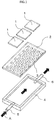
- FIG. 1 is an exploded perspective view for illustrating a heat sink according to a first embodiment of the present invention.
- the heat sink includes a base 2, a plurality of heat-radiating fins 3, a jacket 4, a refrigerant inlet portion 5, and a refrigerant outlet portion 6.
- the base 2 has heat-generating elements 1 provided on a top surface thereof.
- the plurality of heat-radiating fins 3 are provided on a back surface of the base 2.
- the jacket 4 receives the base 2 therein.
- the refrigerant inlet portion 5 is provided on a side wall of the jacket 4.
- the refrigerant outlet portion 6 is provided on a side wall of the jacket 4, which is opposed to the side wall on which the refrigerant inlet portion 5 is provided.
- refrigerant enters the refrigerant inlet portion 5 in a direction indicated by the arrows A of FIG. 1 .
- the refrigerant having entered the refrigerant inlet portion 5 passes through the refrigerant inlet portion 5 to enter a space defined by the jacket 4 and the base 2.
- the refrigerant exchanges heat with the heat-radiating fins 3 that receive heat from theheat-generating elements 1.
- the heat-generating elements 1 are cooled by the heat-radiating fins 3.
- the refrigerant having received heat through the heat exchange with the heat-radiating fins 3 enters the refrigerant outlet portion 6 as it is.
- the refrigerant having entered the refrigerant outlet portion 6 passes through the refrigerant outlet portion 6 to be discharged to the outside of the heat sink.
- the refrigerant to be used in the heat sink may be any of liquid, gas, and gas-liquid mixture. Further, the jacket 4 may be omitted from the heat sink depending on an environment in which the heat sink is installed.
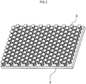
- FIG. 2 is a perspective view for illustrating the heat-radiating fins 3 and the base 2 of FIG. 1 .
- FIG. 3 is an illustration of seven heat-radiating fins 3 of FIG. 2 as viewed in a direction perpendicular to the base 2.
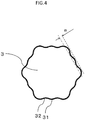
- FIG. 4 is an enlarged view for illustrating one heat-radiating fin 3 of FIG. 3 .
- the heat-radiating fins 3 are each formed so that a sectional shape thereof along the base 2 is inscribed in a regular hexagon.
- the broken line indicates the regular hexagon circumscribed to the heat-radiating fin 3.
- a distance between facing sides of the regular hexagon circumscribed to one heat-radiating fin 3 is defined as an opposite side distance "w".
- the heat-radiating fin 3 has a projection-and-recess shape in cross section, which is inscribed in the regular hexagon.
- the heat-radiating fin 3 has projections 31 and recesses 32.
- the projections 31 are held in contact with the regular hexagon, and the recesses 32 are apart from the regular hexagon .
- the plurality of recesses 32 are arranged so as to be opposed to the sides of the regular hexagon. A distance between the side of the regular hexagon, which is circumscribed to the heat-radiating fin 3, and a common tangent of the plurality of recesses 32 opposed to the side and adjacent to each other is defined as a recess depth "a".
- the recess depth "a" is a distance between a bottom portion of the recess 32 of the projection-and-recess shape and the side of the regular hexagon, with which the projection 31 is held in contact.
- the broken line indicates a line obtained by extending one side of the regular hexagon, and the dashed-dotted line indicates the common tangent of the recesses 32 adjacent to each other.
- Six heat-radiating fins 3 are arranged around one heat-radiating fin 3.
- the six heat-radiating fins 3 are arrayed in a circumferential direction around the one heat-radiating fin 3 as a center.
- the respective sides of the regular hexagon, which are circumscribed to the one heat-radiating fin 3, are opposed to the respective sides of the regular hexagons, which are circumscribed to the respective heat-radiating fins 3 around the one heat-radiating fin 3.
- the sides of the regular hexagon, which are circumscribed to the one heat-radiating fin 3, and the sides of the regular hexagons, which are circumscribed to the respective six heat-radiating fins 3 arranged around the one heat-radiating fin 3, are apart from each other and are opposed to each other in an entire region.
- a distance between each of the sides of the regular hexagon, which are circumscribed to the one heat-radiating fin 3, and each of the sides of the regular hexagons circumscribed to the six heat-radiating fins 3 arranged around the one heat-radiating fin 3 is defined as a side-to-side distance "t".
- the root portion of the heat-radiating fin 3 maybe formed so as to have a corner R, in other words, to have roundness .
- the heat-radiating fin 3 may be formed into a tapered shape, which is tapered as separating from the base 2 in a perpendicular direction.
- the side-to-side distance "t" only needs to be a side-to-side distance "t” at an average height of the heat-radiating fins 3 each having a tapered shape.
- the average height is, for example, a height at an intermediate portion when the heat-radiating fin 3 is inclined linearly.
- the sides of the regular hexagons, which are circumscribed to the heat-radiating fins 3, are opposed to each other in an entire region at the side-to-side distance "t".
- the heat-radiating fins 3 are most densely arranged at the side-to-side distance "t” so that the surface area of the heat-radiating fins 3 is increased. Therefore, even when a limitation of a lower limit value of the side-to-side distance "t", which is imposed so as to prevent clogging of foreign matters such as dust, is set, the heat radiation performance of the heat sink can be enhanced within the limitations.
- refrigerant collides against the projections 31 of the projection-and-recess shape formed on each of side surfaces of the heat-radiating fin 3.
- a flow of the refrigerant is stirred, and a temperature boundary layer is thinned, thereby being capable of further enhancing the heat radiation performance of the heat sink.
- the heat-radiating fins 3 when the side-to-side distance "t" is fixed, as the opposite side distance "w” is larger, thermal resistance from the root to the distal end of each of the heat-radiating fins 3 is reduced. Thus, the entire side surfaces of the heat-radiating fins 3 can be used for heat radiation efficiently, that is, fin efficiency is enhanced. However, as the opposite side distance "w” is larger, the number of the heat-radiating fins 3 that can be arranged per unit area is reduced, which results in reduction in heat radiation area of the heat sink.
- FIG. 5 is a graph for showing a relationship between the opposite side distance "w" of the heat-radiating fin 3 and a heat transfer coefficient.
- the horizontal axis represents the opposite side distance "w” of the heat-radiating fin 3
- the vertical axis represents the heat transfer coefficient (freely selected unit) .
- FIG. 5 there is shown a result of performing a three-dimensional thermal fluid simulation under a condition that the side-to-side distance "t", the recess depth "a", a height of the heat-radiating fin 3, and a refrigerant flow rate are fixed.
- the heat transfer coefficient becomes the maximum when the opposite side distance "w" is around 2.5 mm.
- the opposite side distance "w” is set to from 2.0 mm to 3.1 mm, 70% of the maximum value of the heat transfer coefficient can be obtained, thereby being capable of particularly enhancing the heat radiation performance of the heat sink.
- Configurations other than setting of the opposite side distance "w" to from 2.0 mm to 3.1 mm are the same as those of the first embodiment.
- the opposite side distance "w" is from 2.0 mm to 3.1 mm, thereby being capable of particularly enhancing the heat radiation performance.
- the flow of the refrigerant is further stirred at the projections 31 formed on the side surfaces of the heat-radiating fin 3, and an effect of thinning the temperature boundary layer is larger, which results in increase in heat radiation amount of the heat sink.
- the recess depth "a" of the heat-radiating fin 3 is larger, the refrigerant flow speed is lowered at the recesses 32 in the side surfaces of the heat-radiating fin 3, which results in reduction in heat radiation amount of the heat sink.
- the recess depth "a" of the heat-radiating fin 3 is smaller, stirring of the flow of the refrigerant is reduced at the projections 31 on the side surfaces, and the effect of thinning the temperature boundary layer is reduced, which results in reduction in heat radiation amount of the heat sink.
- the recess depth "a" of the heat-radiating fin 3 is smaller, lowering of the refrigerant flow speed is suppressed at the recesses 32 in the side surfaces of the heat-radiating fin 3, which results in increase in heat radiation amount of the heat sink.
- the effect of thinning the temperature boundary layer on the projections 31 and the refrigerant flow speed in the recesses 32 have a trade-off relation, and there is an optimum value for the recess depth "a".
- FIG. 6 is a graph for showing a relationship between the recess depth "a” and a heat transfer coefficient.
- the horizontal axis represents the recess depth "a” of the heat-radiating fin 3
- the vertical axis represents the heat transfer coefficient (freely selected unit).
- FIG. 6 there is shown a result of performing a three-dimensional thermal fluid simulation under a condition that the side-to-side distance "t", the opposite side distance "w", a height of the heat-radiating fin 3, and a refrigerant flow rate are fixed.
- the heat transfer coefficient becomes the maximum when the recess depth "a" is around 0.1 mm.
- the recess depth "a” is set to from 0.05 mm to 0.15 mm, 70% of the maximum value of the heat transfer coefficient can be obtained, thereby being capable of particularly enhancing the heat radiation performance of the heat sink.
- Configurations other than the configuration that setting of the recess depth "a" to from 0.05 mm to 0.15 mm are the same as those of the first embodiment or the second embodiment.
- the recess depth "a" is from 0.05 mm to 0.15 mm, thereby being capable of particularly enhancing the heat radiation performance.
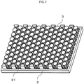
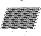
- FIG. 7 is a perspective view for illustrating heat-radiating fins and a base of a heat sink according to a fourth embodiment of the present invention.
- FIG. 8 is a perspective view for illustrating the base in a state in which the heat-radiating fins are removed from the heat sink of FIG. 7 .
- a projection-and-recess portion 21 having a zig-zag shape is formed on the base 2. With the projection-and-recess portion 21 having a zig-zag shape, the flow of the refrigerant is stirred intricately when the refrigerant passes between the heat-radiating fins 3, a temperature boundary layer formed on the base 2 is thinned, and heat radiation of the heat sink is promoted.
- Other configurations are the same as those of the first embodiment to the third embodiment.
- the projection-and-recess portion 21 is formed on the base 2, and the projection-and-recess portion 21 is formed into a zig-zag shape.
- a temperature boundary layer formed on the base 2 can be thinned, thereby being capable of further promoting heat radiation.
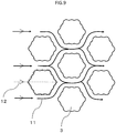
- FIG. 9 is a plan view for illustrating a plurality of heat-radiating fins in a heat sink according to a fifth embodiment of the present invention.
- the heat-radiating fins 3 as viewed in an axial direction of the heat-radiating fins 3 are illustrated.
- one heat-radiating fin 3 and six heat-radiating fins 3 provided around the one heat-radiating fin 3 are illustrated.
- a flow passage direction 11 of refrigerant passing between the adjacent heat-radiating fins 3 is indicated.
- the refrigerant passing through the heat sink flows in parallel to a straight line 12 connecting apexes of the regular hexagon circumscribed to the heat-radiating fin 3.
- the heat-radiating fins 3 are arranged so that the refrigerant flows along the straight line 12 connecting the apexes of the regular hexagon circumscribed to the heat-radiating fin 3.
- the straight line 12 connecting the apexes of the regular hexagon circumscribed to the heat-radiating fin 3 is a straight line 12 connecting the respective apexes of the regular hexagon circumscribed to the heat-radiating fin 3, that is, a pair of apexes opposed to each other.
- the refrigerant is caused to flow in parallel to the straight line connecting the apexes of the regular hexagon circumscribed to the heat-radiating fin 3.
- the side surfaces of the heat-radiating fins 3 can be used efficiently for heat radiation.
- FIG. 10 is an illustration of a state in which the refrigerant is caused to flow perpendicularly to the straight line connecting the apexes of the regular hexagon circumscribed to the heat-radiating fin 3.
- FIG. 10 when the refrigerant is caused to flow perpendicularly to the straight line connecting the apexes of the regular hexagon circumscribed to the heat-radiating fin 3, a stagnation region 13 of the refrigerant is generated in a direction orthogonal to the flow of the refrigerant. Sufficient heat radiation does not occur at the side surfaces of the heat-radiating fins 3 adjacent to the stagnation region 13 of the refrigerant.
- FIG. 10 is an illustration of a state in which the refrigerant is caused to flow perpendicularly to the straight line connecting the apexes of the regular hexagon circumscribed to the heat-radiating fin 3.
- the heat-radiating fins 3 are arranged so that the refrigerant flows in parallel to the straight line connecting the apexes of the regular hexagon circumscribed to the heat-radiating fin 3. Therefore, the stagnation region 13 of the refrigerant is not generated, thereby being capable of further enhancing the heat radiation performance of the heat sink.
Applications Claiming Priority (1)
| Application Number | Priority Date | Filing Date | Title |
|---|---|---|---|
| PCT/JP2016/063858 WO2017195270A1 (fr) | 2016-05-10 | 2016-05-10 | Dissipateur thermique |
Publications (3)
| Publication Number | Publication Date |
|---|---|
| EP3457828A1 true EP3457828A1 (fr) | 2019-03-20 |
| EP3457828A4 EP3457828A4 (fr) | 2019-05-22 |
| EP3457828B1 EP3457828B1 (fr) | 2021-04-07 |
Family
ID=60266434
Family Applications (1)
| Application Number | Title | Priority Date | Filing Date |
|---|---|---|---|
| EP16901619.3A Active EP3457828B1 (fr) | 2016-05-10 | 2016-05-10 | Dissipateur thermique |
Country Status (5)
| Country | Link |
|---|---|
| US (1) | US10809017B2 (fr) |
| EP (1) | EP3457828B1 (fr) |
| JP (1) | JP6692417B2 (fr) |
| CN (1) | CN109076716B (fr) |
| WO (1) | WO2017195270A1 (fr) |
Families Citing this family (9)
| Publication number | Priority date | Publication date | Assignee | Title |
|---|---|---|---|---|
| CN108024486A (zh) * | 2018-01-04 | 2018-05-11 | 钦州学院 | 基于蜻蜓翅膀微观表面的微型散热器及其制造方法 |
| WO2020020619A1 (fr) * | 2018-07-23 | 2020-01-30 | Siemens Aktiengesellschaft | Refroidissement de composants, convertisseur de courant et aéronef |
| JP6789335B2 (ja) * | 2019-03-05 | 2020-11-25 | 三菱電機株式会社 | ヒートシンク及びこれを備えた半導体モジュール |
| JP7205662B2 (ja) * | 2020-03-18 | 2023-01-17 | 富士電機株式会社 | 半導体モジュール |
| JP2021197397A (ja) * | 2020-06-10 | 2021-12-27 | 尼得科超▲しゅう▼科技股▲ふん▼有限公司 | ヒートシンクの製造方法 |
| CN112188796B (zh) * | 2020-09-07 | 2022-01-25 | 杭州电子科技大学 | 内置仿小肠绒毛式微针环的大功率芯片散热系统与方法 |
| KR102378897B1 (ko) * | 2020-10-19 | 2022-03-28 | 주식회사 고산 | 배터리 및 연료전지스택용 열교환기 |
| CN112377468A (zh) * | 2020-11-06 | 2021-02-19 | 广州菲亚兰德科技有限公司 | 一种散热面板及散热设备 |
| CN115966531A (zh) * | 2023-01-13 | 2023-04-14 | 广州小鹏汽车科技有限公司 | 功率模块的散热系统 |
Family Cites Families (36)
| Publication number | Priority date | Publication date | Assignee | Title |
|---|---|---|---|---|
| JPH04167549A (ja) * | 1990-10-31 | 1992-06-15 | Matsushita Electric Ind Co Ltd | 半導体装置 |
| JPH07310998A (ja) * | 1994-05-17 | 1995-11-28 | Kankyo Kagaku Kogyo Kk | 熱交換器 |
| JPH09138091A (ja) | 1995-11-16 | 1997-05-27 | Rokuro Shimada | 放熱板 |
| JPH09162333A (ja) * | 1995-12-07 | 1997-06-20 | Janome Sewing Mach Co Ltd | Lsi用ヒートシンク |
| JPH09252066A (ja) * | 1996-03-15 | 1997-09-22 | Mitsubishi Electric Corp | ヒートシンク |
| JP3431004B2 (ja) * | 2000-01-14 | 2003-07-28 | 松下電器産業株式会社 | ヒートシンクおよびそれを用いた冷却装置 |
| US6729383B1 (en) * | 1999-12-16 | 2004-05-04 | The United States Of America As Represented By The Secretary Of The Navy | Fluid-cooled heat sink with turbulence-enhancing support pins |
| JP3840970B2 (ja) * | 2001-12-18 | 2006-11-01 | 日本電気株式会社 | ヒートシンク |
| JP2004103734A (ja) | 2002-09-06 | 2004-04-02 | Furukawa Electric Co Ltd:The | ヒートシンクおよびその製造方法 |
| US6919504B2 (en) * | 2002-12-19 | 2005-07-19 | 3M Innovative Properties Company | Flexible heat sink |
| US20070053168A1 (en) * | 2004-01-21 | 2007-03-08 | General Electric Company | Advanced heat sinks and thermal spreaders |
| JP4027353B2 (ja) * | 2004-09-28 | 2007-12-26 | 三菱電機株式会社 | 冷却構造 |
| CN100412495C (zh) * | 2005-06-17 | 2008-08-20 | 周惠敏 | 带覆层的热交换器 |
| TW200926945A (en) * | 2007-12-12 | 2009-06-16 | chong-xian Huang | Cylindrical heat dissipater equipped with cooling fins |
| JP2012518254A (ja) * | 2009-02-17 | 2012-08-09 | カオ グループ、インク. | 空間照明用のled電球 |
| DE102010000875B4 (de) | 2010-01-13 | 2014-05-22 | Infineon Technologies Ag | Verfahren zur Messung der Junction-Temperatur bei Leistungshalbleitern in einem Stromrichter |
| CN201688705U (zh) * | 2010-03-05 | 2010-12-29 | 郑州安耐克实业有限公司 | 多孔波浪形蜂窝格子砖 |
| CN201894036U (zh) * | 2010-11-19 | 2011-07-06 | 武汉热诺金属科技有限公司 | 蜂窝状水冷散热器 |
| JP5770519B2 (ja) | 2011-04-20 | 2015-08-26 | 株式会社日本自動車部品総合研究所 | 冷却フィン構造 |
| WO2012157247A1 (fr) | 2011-05-16 | 2012-11-22 | 富士電機株式会社 | Refroidisseur destiné à être utilisé dans un module à semi-conducteur |
| JP2013138193A (ja) | 2011-11-28 | 2013-07-11 | Kyocera Corp | ヒートシンクおよびこのヒートシンクを備えた電子部品装置 |
| JP5878352B2 (ja) | 2011-12-08 | 2016-03-08 | 昭和電工株式会社 | ヒートシンク |
| FR3002646B1 (fr) | 2013-02-22 | 2015-04-17 | Technofan | Capteur electronique de temperature pour mesurer la temperature de jonction d'un interrupteur electronique de puissance en fonctionnement et procede de mesure de la temperature de la jonction par ce capteur electronique |
| US10986933B2 (en) * | 2013-03-15 | 2021-04-27 | Kryo, Inc. | Article comprising a temperature-conditioned surface, thermoelectric control unit, and method for temperature-conditioning the surface of an article |
| CN204084590U (zh) * | 2014-10-09 | 2015-01-07 | 广东美的环境电器制造有限公司 | 油汀散热片及电热油汀 |
| EP3209965B1 (fr) * | 2014-10-20 | 2018-06-13 | Philips Lighting Holding B.V. | Dissipateur thermique à ailettes sur tube léger |
| US20160146405A1 (en) * | 2014-11-25 | 2016-05-26 | Posco Led Company Ltd. | Optical semiconductor lighting apparatus |
| JP6132869B2 (ja) | 2015-04-07 | 2017-05-24 | 三菱電機株式会社 | ヒートシンク |
| WO2016194158A1 (fr) * | 2015-06-03 | 2016-12-08 | 三菱電機株式会社 | Refroidisseur à refroidissement par liquide, et procédé de fabrication d'ailette de radiateur dans un refroidisseur à refroidissement par liquide |
| CN104990051A (zh) * | 2015-07-18 | 2015-10-21 | 朱大龙 | 大小圆弧散热片列阵组成的散热器 |
| US9638477B1 (en) * | 2015-10-13 | 2017-05-02 | Caterpillar, Inc. | Sealless cooling device having manifold and turbulator |
| WO2018003138A1 (fr) * | 2016-07-01 | 2018-01-04 | かがつう株式会社 | Dissipateur thermique et paquet de composant électronique |
| US20180142964A1 (en) * | 2016-11-21 | 2018-05-24 | Abl Ip Holding Llc | Heatsink |
| US10415895B2 (en) * | 2016-11-21 | 2019-09-17 | Abl Ip Holding Llc | Heatsink |
| JP6462737B2 (ja) * | 2017-01-24 | 2019-01-30 | 三菱電機株式会社 | ヒートシンク |
| US20200008316A1 (en) * | 2018-06-28 | 2020-01-02 | Carbice Corporation | Flexible and conformable heat sinks and methods of making and using thereof |
-
2016
- 2016-05-10 US US16/093,727 patent/US10809017B2/en active Active
- 2016-05-10 WO PCT/JP2016/063858 patent/WO2017195270A1/fr unknown
- 2016-05-10 CN CN201680085387.2A patent/CN109076716B/zh active Active
- 2016-05-10 EP EP16901619.3A patent/EP3457828B1/fr active Active
- 2016-05-10 JP JP2018516245A patent/JP6692417B2/ja active Active
Also Published As
| Publication number | Publication date |
|---|---|
| US20190137195A1 (en) | 2019-05-09 |
| EP3457828B1 (fr) | 2021-04-07 |
| JPWO2017195270A1 (ja) | 2018-08-02 |
| CN109076716B (zh) | 2020-10-27 |
| JP6692417B2 (ja) | 2020-05-13 |
| EP3457828A4 (fr) | 2019-05-22 |
| CN109076716A (zh) | 2018-12-21 |
| US10809017B2 (en) | 2020-10-20 |
| WO2017195270A1 (fr) | 2017-11-16 |
Similar Documents
| Publication | Publication Date | Title |
|---|---|---|
| EP3457828B1 (fr) | Dissipateur thermique | |
| CN107615479B (zh) | 液冷冷却器中的散热翅片的制造方法 | |
| CN110226365B (zh) | 散热器 | |
| US11502023B2 (en) | Semiconductor device with partition for refrigerant cooling | |
| JP2007096306A (ja) | ヒートシンク | |
| JP2008205421A (ja) | 熱交換器 | |
| JP2012216711A (ja) | ヒートシンク、およびヒートシンク付き電子部品 | |
| US10809011B2 (en) | Heat sink | |
| CN111668177B (zh) | 散热器及具备该散热器的半导体模块 | |
| KR102296543B1 (ko) | 수냉식 히트싱크 | |
| US20170280588A1 (en) | Heat dissipating device | |
| JP6138197B2 (ja) | 液冷冷却器、及び液冷冷却器に於ける放熱フィンの製造方法 | |
| US6943444B2 (en) | Cooling of surface temperature of a device | |
| JP6132869B2 (ja) | ヒートシンク | |
| US20160252311A1 (en) | Wavy Fin Structure and Flat Tube Heat Exchanger Having the Same | |
| EP3907584A1 (fr) | Ensemble plaque froide adapté | |
| WO2015114899A1 (fr) | Dispositif de refroidissement et procédé de production de dispositif de refroidissement | |
| JP7157591B2 (ja) | ヒートシンク | |
| EP3023727A1 (fr) | Plaque de guidage de fluide et échangeur de plaque associé | |
| CN114639647A (zh) | 微流道散热结构和微电子芯片结构 | |
| JP6868415B2 (ja) | 熱交換器用ヒートシンク及び熱交換器 | |
| JP5251916B2 (ja) | 電子機器の冷却器 | |
| CN215819168U (zh) | 散热器、热交换装置 | |
| CN215956923U (zh) | 散热器、热交换装置 | |
| CN215735489U (zh) | 散热器、热交换装置 |
Legal Events
| Date | Code | Title | Description |
|---|---|---|---|
| STAA | Information on the status of an ep patent application or granted ep patent |
Free format text: STATUS: THE INTERNATIONAL PUBLICATION HAS BEEN MADE |
|
| PUAI | Public reference made under article 153(3) epc to a published international application that has entered the european phase |
Free format text: ORIGINAL CODE: 0009012 |
|
| STAA | Information on the status of an ep patent application or granted ep patent |
Free format text: STATUS: REQUEST FOR EXAMINATION WAS MADE |
|
| 17P | Request for examination filed |
Effective date: 20181018 |
|
| AK | Designated contracting states |
Kind code of ref document: A1 Designated state(s): AL AT BE BG CH CY CZ DE DK EE ES FI FR GB GR HR HU IE IS IT LI LT LU LV MC MK MT NL NO PL PT RO RS SE SI SK SM TR |
|
| AX | Request for extension of the european patent |
Extension state: BA ME |
|
| A4 | Supplementary search report drawn up and despatched |
Effective date: 20190426 |
|
| RIC1 | Information provided on ipc code assigned before grant |
Ipc: H05K 7/20 20060101AFI20190418BHEP Ipc: F28F 3/12 20060101ALI20190418BHEP Ipc: F28D 21/00 20060101ALI20190418BHEP Ipc: F28F 3/02 20060101ALI20190418BHEP Ipc: F28F 3/04 20060101ALI20190418BHEP |
|
| DAV | Request for validation of the european patent (deleted) | ||
| DAX | Request for extension of the european patent (deleted) | ||
| GRAP | Despatch of communication of intention to grant a patent |
Free format text: ORIGINAL CODE: EPIDOSNIGR1 |
|
| STAA | Information on the status of an ep patent application or granted ep patent |
Free format text: STATUS: GRANT OF PATENT IS INTENDED |
|
| INTG | Intention to grant announced |
Effective date: 20201126 |
|
| GRAS | Grant fee paid |
Free format text: ORIGINAL CODE: EPIDOSNIGR3 |
|
| GRAA | (expected) grant |
Free format text: ORIGINAL CODE: 0009210 |
|
| STAA | Information on the status of an ep patent application or granted ep patent |
Free format text: STATUS: THE PATENT HAS BEEN GRANTED |
|
| AK | Designated contracting states |
Kind code of ref document: B1 Designated state(s): AL AT BE BG CH CY CZ DE DK EE ES FI FR GB GR HR HU IE IS IT LI LT LU LV MC MK MT NL NO PL PT RO RS SE SI SK SM TR |
|
| REG | Reference to a national code |
Ref country code: GB Ref legal event code: FG4D |
|
| REG | Reference to a national code |
Ref country code: AT Ref legal event code: REF Ref document number: 1381407 Country of ref document: AT Kind code of ref document: T Effective date: 20210415 Ref country code: CH Ref legal event code: EP |
|
| REG | Reference to a national code |
Ref country code: DE Ref legal event code: R096 Ref document number: 602016055911 Country of ref document: DE |
|
| REG | Reference to a national code |
Ref country code: IE Ref legal event code: FG4D |
|
| REG | Reference to a national code |
Ref country code: LT Ref legal event code: MG9D |
|
| REG | Reference to a national code |
Ref country code: NL Ref legal event code: MP Effective date: 20210407 Ref country code: AT Ref legal event code: MK05 Ref document number: 1381407 Country of ref document: AT Kind code of ref document: T Effective date: 20210407 |
|
| PG25 | Lapsed in a contracting state [announced via postgrant information from national office to epo] |
Ref country code: LT Free format text: LAPSE BECAUSE OF FAILURE TO SUBMIT A TRANSLATION OF THE DESCRIPTION OR TO PAY THE FEE WITHIN THE PRESCRIBED TIME-LIMIT Effective date: 20210407 Ref country code: FI Free format text: LAPSE BECAUSE OF FAILURE TO SUBMIT A TRANSLATION OF THE DESCRIPTION OR TO PAY THE FEE WITHIN THE PRESCRIBED TIME-LIMIT Effective date: 20210407 Ref country code: AT Free format text: LAPSE BECAUSE OF FAILURE TO SUBMIT A TRANSLATION OF THE DESCRIPTION OR TO PAY THE FEE WITHIN THE PRESCRIBED TIME-LIMIT Effective date: 20210407 Ref country code: BG Free format text: LAPSE BECAUSE OF FAILURE TO SUBMIT A TRANSLATION OF THE DESCRIPTION OR TO PAY THE FEE WITHIN THE PRESCRIBED TIME-LIMIT Effective date: 20210707 Ref country code: HR Free format text: LAPSE BECAUSE OF FAILURE TO SUBMIT A TRANSLATION OF THE DESCRIPTION OR TO PAY THE FEE WITHIN THE PRESCRIBED TIME-LIMIT Effective date: 20210407 Ref country code: NL Free format text: LAPSE BECAUSE OF FAILURE TO SUBMIT A TRANSLATION OF THE DESCRIPTION OR TO PAY THE FEE WITHIN THE PRESCRIBED TIME-LIMIT Effective date: 20210407 |
|
| PG25 | Lapsed in a contracting state [announced via postgrant information from national office to epo] |
Ref country code: RS Free format text: LAPSE BECAUSE OF FAILURE TO SUBMIT A TRANSLATION OF THE DESCRIPTION OR TO PAY THE FEE WITHIN THE PRESCRIBED TIME-LIMIT Effective date: 20210407 Ref country code: SE Free format text: LAPSE BECAUSE OF FAILURE TO SUBMIT A TRANSLATION OF THE DESCRIPTION OR TO PAY THE FEE WITHIN THE PRESCRIBED TIME-LIMIT Effective date: 20210407 Ref country code: NO Free format text: LAPSE BECAUSE OF FAILURE TO SUBMIT A TRANSLATION OF THE DESCRIPTION OR TO PAY THE FEE WITHIN THE PRESCRIBED TIME-LIMIT Effective date: 20210707 Ref country code: PT Free format text: LAPSE BECAUSE OF FAILURE TO SUBMIT A TRANSLATION OF THE DESCRIPTION OR TO PAY THE FEE WITHIN THE PRESCRIBED TIME-LIMIT Effective date: 20210809 Ref country code: PL Free format text: LAPSE BECAUSE OF FAILURE TO SUBMIT A TRANSLATION OF THE DESCRIPTION OR TO PAY THE FEE WITHIN THE PRESCRIBED TIME-LIMIT Effective date: 20210407 Ref country code: LV Free format text: LAPSE BECAUSE OF FAILURE TO SUBMIT A TRANSLATION OF THE DESCRIPTION OR TO PAY THE FEE WITHIN THE PRESCRIBED TIME-LIMIT Effective date: 20210407 Ref country code: GR Free format text: LAPSE BECAUSE OF FAILURE TO SUBMIT A TRANSLATION OF THE DESCRIPTION OR TO PAY THE FEE WITHIN THE PRESCRIBED TIME-LIMIT Effective date: 20210708 Ref country code: IS Free format text: LAPSE BECAUSE OF FAILURE TO SUBMIT A TRANSLATION OF THE DESCRIPTION OR TO PAY THE FEE WITHIN THE PRESCRIBED TIME-LIMIT Effective date: 20210807 |
|
| REG | Reference to a national code |
Ref country code: CH Ref legal event code: PL |
|
| REG | Reference to a national code |
Ref country code: DE Ref legal event code: R097 Ref document number: 602016055911 Country of ref document: DE |
|
| PG25 | Lapsed in a contracting state [announced via postgrant information from national office to epo] |
Ref country code: CH Free format text: LAPSE BECAUSE OF NON-PAYMENT OF DUE FEES Effective date: 20210531 Ref country code: DK Free format text: LAPSE BECAUSE OF FAILURE TO SUBMIT A TRANSLATION OF THE DESCRIPTION OR TO PAY THE FEE WITHIN THE PRESCRIBED TIME-LIMIT Effective date: 20210407 Ref country code: CZ Free format text: LAPSE BECAUSE OF FAILURE TO SUBMIT A TRANSLATION OF THE DESCRIPTION OR TO PAY THE FEE WITHIN THE PRESCRIBED TIME-LIMIT Effective date: 20210407 Ref country code: EE Free format text: LAPSE BECAUSE OF FAILURE TO SUBMIT A TRANSLATION OF THE DESCRIPTION OR TO PAY THE FEE WITHIN THE PRESCRIBED TIME-LIMIT Effective date: 20210407 Ref country code: MC Free format text: LAPSE BECAUSE OF FAILURE TO SUBMIT A TRANSLATION OF THE DESCRIPTION OR TO PAY THE FEE WITHIN THE PRESCRIBED TIME-LIMIT Effective date: 20210407 Ref country code: LU Free format text: LAPSE BECAUSE OF NON-PAYMENT OF DUE FEES Effective date: 20210510 Ref country code: LI Free format text: LAPSE BECAUSE OF NON-PAYMENT OF DUE FEES Effective date: 20210531 Ref country code: ES Free format text: LAPSE BECAUSE OF FAILURE TO SUBMIT A TRANSLATION OF THE DESCRIPTION OR TO PAY THE FEE WITHIN THE PRESCRIBED TIME-LIMIT Effective date: 20210407 Ref country code: RO Free format text: LAPSE BECAUSE OF FAILURE TO SUBMIT A TRANSLATION OF THE DESCRIPTION OR TO PAY THE FEE WITHIN THE PRESCRIBED TIME-LIMIT Effective date: 20210407 Ref country code: SM Free format text: LAPSE BECAUSE OF FAILURE TO SUBMIT A TRANSLATION OF THE DESCRIPTION OR TO PAY THE FEE WITHIN THE PRESCRIBED TIME-LIMIT Effective date: 20210407 Ref country code: SK Free format text: LAPSE BECAUSE OF FAILURE TO SUBMIT A TRANSLATION OF THE DESCRIPTION OR TO PAY THE FEE WITHIN THE PRESCRIBED TIME-LIMIT Effective date: 20210407 |
|
| REG | Reference to a national code |
Ref country code: BE Ref legal event code: MM Effective date: 20210531 |
|
| PLBE | No opposition filed within time limit |
Free format text: ORIGINAL CODE: 0009261 |
|
| STAA | Information on the status of an ep patent application or granted ep patent |
Free format text: STATUS: NO OPPOSITION FILED WITHIN TIME LIMIT |
|
| 26N | No opposition filed |
Effective date: 20220110 |
|
| GBPC | Gb: european patent ceased through non-payment of renewal fee |
Effective date: 20210707 |
|
| PG25 | Lapsed in a contracting state [announced via postgrant information from national office to epo] |
Ref country code: IE Free format text: LAPSE BECAUSE OF NON-PAYMENT OF DUE FEES Effective date: 20210510 Ref country code: GB Free format text: LAPSE BECAUSE OF NON-PAYMENT OF DUE FEES Effective date: 20210707 |
|
| PG25 | Lapsed in a contracting state [announced via postgrant information from national office to epo] |
Ref country code: IS Free format text: LAPSE BECAUSE OF FAILURE TO SUBMIT A TRANSLATION OF THE DESCRIPTION OR TO PAY THE FEE WITHIN THE PRESCRIBED TIME-LIMIT Effective date: 20210807 Ref country code: AL Free format text: LAPSE BECAUSE OF FAILURE TO SUBMIT A TRANSLATION OF THE DESCRIPTION OR TO PAY THE FEE WITHIN THE PRESCRIBED TIME-LIMIT Effective date: 20210407 |
|
| PG25 | Lapsed in a contracting state [announced via postgrant information from national office to epo] |
Ref country code: IT Free format text: LAPSE BECAUSE OF FAILURE TO SUBMIT A TRANSLATION OF THE DESCRIPTION OR TO PAY THE FEE WITHIN THE PRESCRIBED TIME-LIMIT Effective date: 20210407 Ref country code: BE Free format text: LAPSE BECAUSE OF NON-PAYMENT OF DUE FEES Effective date: 20210531 |
|
| P01 | Opt-out of the competence of the unified patent court (upc) registered |
Effective date: 20230512 |
|
| PG25 | Lapsed in a contracting state [announced via postgrant information from national office to epo] |
Ref country code: CY Free format text: LAPSE BECAUSE OF FAILURE TO SUBMIT A TRANSLATION OF THE DESCRIPTION OR TO PAY THE FEE WITHIN THE PRESCRIBED TIME-LIMIT Effective date: 20210407 |
|
| REG | Reference to a national code |
Ref country code: DE Ref legal event code: R084 Ref document number: 602016055911 Country of ref document: DE |
|
| PG25 | Lapsed in a contracting state [announced via postgrant information from national office to epo] |
Ref country code: HU Free format text: LAPSE BECAUSE OF FAILURE TO SUBMIT A TRANSLATION OF THE DESCRIPTION OR TO PAY THE FEE WITHIN THE PRESCRIBED TIME-LIMIT; INVALID AB INITIO Effective date: 20160510 |
|
| PGFP | Annual fee paid to national office [announced via postgrant information from national office to epo] |
Ref country code: FR Payment date: 20230411 Year of fee payment: 8 Ref country code: DE Payment date: 20230331 Year of fee payment: 8 |