EP3457076A1 - Wirkkörper mit bremsdeckel - Google Patents
Wirkkörper mit bremsdeckel Download PDFInfo
- Publication number
- EP3457076A1 EP3457076A1 EP18190148.9A EP18190148A EP3457076A1 EP 3457076 A1 EP3457076 A1 EP 3457076A1 EP 18190148 A EP18190148 A EP 18190148A EP 3457076 A1 EP3457076 A1 EP 3457076A1
- Authority
- EP
- European Patent Office
- Prior art keywords
- active body
- brake
- cover
- charge
- housing
- Prior art date
- Legal status (The legal status is an assumption and is not a legal conclusion. Google has not performed a legal analysis and makes no representation as to the accuracy of the status listed.)
- Granted
Links
Images

Classifications
-
- F—MECHANICAL ENGINEERING; LIGHTING; HEATING; WEAPONS; BLASTING
- F42—AMMUNITION; BLASTING
- F42B—EXPLOSIVE CHARGES, e.g. FOR BLASTING, FIREWORKS, AMMUNITION
- F42B10/00—Means for influencing, e.g. improving, the aerodynamic properties of projectiles or missiles; Arrangements on projectiles or missiles for stabilising, steering, range-reducing, range-increasing or fall-retarding
- F42B10/32—Range-reducing or range-increasing arrangements; Fall-retarding means
- F42B10/48—Range-reducing, destabilising or braking arrangements, e.g. impact-braking arrangements; Fall-retarding means, e.g. balloons, rockets for braking or fall-retarding
- F42B10/56—Range-reducing, destabilising or braking arrangements, e.g. impact-braking arrangements; Fall-retarding means, e.g. balloons, rockets for braking or fall-retarding of parachute or paraglider type
-
- F—MECHANICAL ENGINEERING; LIGHTING; HEATING; WEAPONS; BLASTING
- F42—AMMUNITION; BLASTING
- F42B—EXPLOSIVE CHARGES, e.g. FOR BLASTING, FIREWORKS, AMMUNITION
- F42B12/00—Projectiles, missiles or mines characterised by the warhead, the intended effect, or the material
- F42B12/02—Projectiles, missiles or mines characterised by the warhead, the intended effect, or the material characterised by the warhead or the intended effect
- F42B12/36—Projectiles, missiles or mines characterised by the warhead, the intended effect, or the material characterised by the warhead or the intended effect for dispensing materials; for producing chemical or physical reaction; for signalling ; for transmitting information
- F42B12/56—Projectiles, missiles or mines characterised by the warhead, the intended effect, or the material characterised by the warhead or the intended effect for dispensing materials; for producing chemical or physical reaction; for signalling ; for transmitting information for dispensing discrete solid bodies
- F42B12/58—Cluster or cargo ammunition, i.e. projectiles containing one or more submissiles
- F42B12/62—Cluster or cargo ammunition, i.e. projectiles containing one or more submissiles the submissiles being ejected parallel to the longitudinal axis of the projectile
- F42B12/625—Cluster or cargo ammunition, i.e. projectiles containing one or more submissiles the submissiles being ejected parallel to the longitudinal axis of the projectile a single submissile arranged in a carrier missile for being launched or accelerated coaxially; Coaxial tandem arrangement of missiles which are active in the target one after the other
Definitions
- the present invention relates to an active body for the application of at least one effect charge as well as a corresponding projectile, which includes the aforementioned active body.
- Such active bodies often have pyrotechnic charges as effect charge and are thus known as pyrotechnic filament or as a mist body as a special form of the pyrotechnic filament.
- a corresponding, inventive active body should burn as evenly as possible and thus uniformly disperse its active charge over a longer period of time. For this purpose, it is first necessary that a reliable lighting and / or decomposition of the effect charge is ensured in the active body. This is mainly dependent on the damming of the active body.
- a corresponding mist throwing body as an active body is for example from the DE 10 2010 026 641 A1 known.
- the active body described there has in addition to the features already mentioned a delay charge, which causes a delayed effect of the effect charge.
- the delay elements known from the prior art which ensure that the ignition of the effect charge does not occur until after a certain time, are susceptible to errors or, due to special requirements, provided with ingredients which are no longer available on the market by corresponding specifications (ingredients for corresponding effect charges must be REACh compliant).
- the object of the present invention to provide an active body, which reduces the impact speed and provides a reliable ignition without delay elements. It is also an object of the present invention to ensure a homogeneous and performance-oriented burn-up and to maintain the internal pressure during combustion of the cladding.
- the invention proposes an active body for applying at least one effect charge, wherein this effect charge may be a flare, a mist set or other Irritations accounts. Likewise, several effect charges may be provided in one active body.
- the effect charge is arranged in the active body and is applied by decomposition or burning.
- the active body has for this purpose a circumferential jacket, which has two ends. These two ends of the shell are now covered at one end with a lid and at the other end with a brake cover.
- the lid is designed so that the effect charge can be ignited by means of it. This can be done for example by a dedicated ejection charge.
- the lid is designed so that it is either flammable and thus the effect charge can be ignited by the burning of the lid.
- at least one firing hole is provided in the lid, through which the effect charge can be ignited in the active body.
- the firing bores are designed so that they are arranged radially circumferentially on the cover.
- the firing bores can be arranged on a circular line and preferably designed as a continuous recess.
- the lid opposite the end of the jacket is covered with a brake cover.
- the brake cover has at least one hole and includes a guided through the hole brake loop.
- the brake loop is preferably made of a woven material and thus designed flexible.
- the ends of the brake loop are attached to the active body, preferably on the jacket of the active body.
- the brake cover is attached to the brake loop so that it is detachably arranged on the jacket and can be removed from the active body in solution of the jacket.
- the maximum distance of the brake cover is limited by the brake loop, since by passing the brake loop through the hole of the brake cover the brake cover is held in a maximum deflection of the brake loop.
- a plurality of holes are provided in the brake cover, so that the brake loop can be passed through these holes.
- the brake cover slips along the brake loop when loosening the coat of the active body.
- the fuel can meander through these be passed.
- the brake loop is preferably made of a woven material, but may be made of any flexible material.
- the holes in the brake cover may be designed to exert a braking force on the movement of the brake pad when moving along the brake loop Exercise brake cover.
- the holes can be made correspondingly narrow or contain clamping elements.
- connecting elements can be designed in a preferred embodiment by pinning.
- recesses are provided on the jacket, in which pins of the lid can engage.
- the invention further proposes a projectile, consisting of a housing which has at least two housing elements.
- a projectile consisting of a housing which has at least two housing elements.
- an active body as described above, arranged.
- the housing elements are preferably connected by a detachable connection and can be solved by applying a certain force from each other.
- a discharge charge is proposed.
- This ejection charge is arranged on the side in the housing on which the lid of the active body is located.
- the discharge charge can ignite the effect charge by the above-mentioned features of the lid.
- the ejection charge can also exert a force on the active body.
- such a discharge charge also consists of a pyrotechnic charge which can be ignited by suitable means.
- the brake cover is released from the shell of the active body and moves along the brake loop until it is held by this in an end position.
- additional projections may be provided on the brake cover to increase the force of the air on the brake cover.
- the brake cover In its final position on the brake loop of the active body of the brake cover now acts as a kind of parachute on the active body and thus ensures that the falling speed of the active body is significantly reduced by the air resistance.
- these are to be dimensioned so that a direct ignition of the effect charge can take place reliably. Ensuring that the lid stays on the body throughout the burn-off period guarantees homogeneous and powerful effect delivery.
- the REACh conformity must be adhered to and a reliable function of the active body ensured, since a possibly error-prone element, namely the delay set, can be dispensed with.
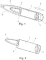
- FIG. 1 shows a projectile according to the invention, which consists of a housing and the housing has an active body 1.
- the active body 1 is arranged in the housing and contains at least one effect charge, which can be applied.
- the application of the effect charge can be done by decomposition or burning.
- the housing of the projectile according to the invention consists of at least two housing elements 6 which are detachably connected to each other to form the housing.
- a brake cover 4 In the longitudinal direction of the active body 1 of the active body is limited in one direction by a brake cover 4 and in the other direction by a lid 3.
- a brake loop 5 On the active body 1, a brake loop 5 is further provided, which are passed through holes on the brake cover 4.
- a discharge charge 7 is provided on the side of the lid 3 in the housing of the projectile according to the invention.
- the ejection charge 7 is arranged in the direction of flight 8 of the throwing body.
- the housing elements 6 are detachably connected to each other, so that when a force is applied to the housing parts 6, the connection is released and the active body 1 can escape from the housing of the throwing body.
- the ejection charge 7 is provided. Upon ignition of the ejection charge 7 by suitable means, a force is exerted on the active body 1 and on the housing elements 6. The exercise of the force on the housing elements 6 can be done directly by the ejection charge or indirectly by the power transmission through the active body. 1
- the power generation causes the discharge charge 7 for lighting the effect charge in the active body 1.
- the lid 3 is designed so that the ejection charge 7 can ignite the effect charge, preferably firing holes are provided in the lid 3.
- FIG. 2 shows an active body 1 according to the invention after application from the projectile.
- the active body 1 according to the invention is in this case enveloped by a jacket 9, wherein the jacket ends are limited by the brake cover 4 and the cover 3.
- the jacket 9 ensures, inter alia, for the damming of the effect charge.
- the lid 3 is connected by suitable fasteners 10 fixed to the jacket 9 of the active body 1.
- These connecting elements 10 may be pins, for example, which can engage in recesses provided in the jacket 9 of the active body 1. Likewise, however, latching connections or adhesive connections are also conceivable.
- firing holes 11 may be provided. At least one such ignition hole 11 is necessary to allow the ignition of the effect charge through the lid 3 therethrough.
- FIG. 5 again shows the implementation 12 of the brake loop 5 through the brake cover 4. Shown here are two holes in the brake cover 4. It can also be provided here several holes. Preferably, the brake loop 5 is then passed meandering through the holes in the brake cover 4.
- the holes in the brake cover 4 may be designed so that they exert a certain frictional force on the brake loop 5. Thus, it is possible to hold the brake cover 4 at one end of the shell 9 and set the required air friction for movement of the brake cover 4 along the brake loop 5.
- the brake loop may consist of rubber
- the ejection charge act electrically or the lid be made combustible.
- measures are necessary to prevent the application of the effect charge in the direction of flight and only to ensure against the direction of flight.
Landscapes
- Engineering & Computer Science (AREA)
- General Engineering & Computer Science (AREA)
- Physics & Mathematics (AREA)
- Fluid Mechanics (AREA)
- Chemical & Material Sciences (AREA)
- Combustion & Propulsion (AREA)
- Lighters Containing Fuel (AREA)
- Aiming, Guidance, Guns With A Light Source, Armor, Camouflage, And Targets (AREA)
- Toys (AREA)
Abstract
Description
- Die vorliegende Erfindung betrifft einen Wirkkörper zur Ausbringung mindestens einer Effektladung sowie einen entsprechenden Wurfkörper, der den vorgenannten Wirkkörper beinhaltet.
- Solche Wirkkörper besitzen häufig pyrotechnische Ladungen als Effektladung und sind somit als pyrotechnische Leuchtkörper bzw. als Nebelkörper als eine besondere Form des pyrotechnischen Leuchtkörpers bekannt.
- Entsprechende Wirkkörper werden in militärischen Anwendungen benötigt, aber auch in zivilen Anwendung, beispielsweise bei Sicherheitskräften.
- Ein entsprechender, erfindungsgemäßer Wirkkörper soll möglichst gleichmäßig abbrennen und somit seine Wirkladung über einen längeren Zeitraum gleichmäßig ausbringen. Dazu ist es zunächst notwendig, dass ein zuverlässiges Anzünden und/oder Zerlegung der Effektladung im Wirkkörper gewährleistet ist. Dieses ist hauptsächlich abhängig von der Verdämmung des Wirkkörpers.
- Um die gleichmäßige Ausbringung der Effektladung zu ermöglichen, ist es wichtig, eine möglichst gleichmäßige Aufrechterhaltung des Innendrucks zu gewährleisten. Bei gleichbleibendem Innendruck während des Abbrands wird eine gleichmäßige Ausbringung der Effektladung gewährleistet.
- Ein entsprechender Nebelwurfkörper als Wirkkörper ist beispielsweise aus der
DE 10 2010 026 641 A1 bekannt. Der dort beschriebene Wirkkörper besitzt zusätzlich zu den bereits genannten Merkmalen eine Verzögerungsladung, welche ein verzögertes Wirksamwerden der Effektladung bewirkt. - Es hat sich gezeigt, dass ein Ausstoß in großer Höhe zu hohen Aufprallgeschwindigkeiten des Wirkkörpers am Boden führen kann. Dies wiederum kann zu einer Spontanumsetzung der Effektladung führen und/oder zu einem Erlöschen des Wirkkörpers. Somit wird auch kein Effekt mehr aus dem Wirkkörper ausgebracht.
- Die aus dem Stand der Technik bekannten Verzögerungselemente, welche dafür sorgen, dass die Entzündung der Effektladung erst nach einer gewissen Zeit geschieht, sind fehleranfällig oder aufgrund von besonderen Anforderungen mit Inhaltsstoffen versehen, welche durch entsprechende Vorgaben nicht mehr auf dem Markt verfügbar sind (Inhaltsstoffe für entsprechende Effektladungen müssen REACh konform ausgeführt sein).
- So ist die Aufgabe der vorliegenden Erfindung, einen Wirkkörper zu schaffen, der die Aufprallgeschwindigkeit reduziert und eine zuverlässige Anzündung ohne Verzögerungselemente bietet. Ebenso ist es Aufgabe der vorliegenden Erfindung, einen homogenen und leistungsorientierte Abbrand zu gewährleisten und den Innendruck beim Abbrand der Verkleidung aufrechtzuerhalten.
- Diese Aufgaben werden mit den Merkmalen des vorliegenden Hauptanspruchs 1 gelöst, sowie durch den Wurfkörper nach Anspruch 12.
- So schlägt die Erfindung einen Wirkkörper zur Ausbringung mindestens einer Effektladung vor, wobei diese Effektladung ein Leuchtsatz sein kann, ein Nebelsatz oder weitere Irritationssätze. Ebenfalls können mehrere Effektladungen in einem Wirkkörper vorgesehen sein.
- Die Effektladung ist in dem Wirkkörper angeordnet und wird ausgebracht durch Zerlegung oder Abbrand.
- Der Wirkkörper besitzt dazu einen umlaufenden Mantel, welcher zwei Enden aufweist. Diese zwei Enden des Mantels sind nun an einem Ende mit einem Deckel abgedeckt und am anderen Ende mit einem Bremsdeckel.
- Der Deckel ist so ausgeführt, dass mittels ihm die Effektladung angezündet werden kann. Dies kann beispielsweise durch eine dafür vorgesehene Ausstoßladung geschehen.
- Dazu ist der Deckel so gestaltet, dass er entweder brennbar ist und somit durch den Abbrand des Deckels auch die Effektladung angezündet werden kann. In einer besonderen Ausführungsform ist jedoch mindestens eine Anzündbohrung im Deckel vorgesehen, durch welche die Effektladung im Wirkkörper hindurch angezündet werden kann.
- Bei Nutzung eines brennbaren Deckels ist dafür zu sorgen, dass die Ausbringung der Effektladung an der dem Deckel abgewandten Seite des Mantels geschieht. Dafür müssen weitere Elemente auf der Seite des Mantels mit dem Deckel vorgesehen sein, welche eine Ausbringung in Richtung Deckel verhindern.
- In einer weiteren besonderen Ausführungsform sind die Anzündbohrungen so gestaltet, dass sie radial umlaufend am Deckel angeordnet sind. Dazu können die Anzündbohrungen auf einer Kreislinie angeordnet sein und vorzugsweise als durchgehende Ausnehmung ausgeführt sein.
- Das dem Deckel gegenüberliegende Ende des Mantels wird mit einem Bremsdeckel abgedeckt. Der Bremsdeckel weist mindestens ein Loch auf und umfasst eine durch das Loch hindurch geführte Bremsschlaufe.
- Die Bremsschlaufe ist bevorzugterweise aus einem gewebten Material gefertigt und somit flexibel gestaltet. Die Enden der Bremsschlaufe sind am Wirkkörper befestigt, bevorzugterweise am Mantel des Wirkkörpers.
- Der Bremsdeckel ist derart an der Bremsschlaufe befestigt, dass er lösbar am Mantel angeordnet ist und sich bei Lösung vom Mantel vom Wirkkörper entfernen kann. Die maximale Entfernung des Bremsdeckels wird durch die Bremsschlaufe begrenzt, da durch das Durchführen der Bremsschlaufe durch das Loch des Bremsdeckels der Bremsdeckel in einer maximalen Auslenkung von der Bremsschlaufe gehalten wird.
- In einer bevorzugten Ausführungsform sind mehrere Löcher im Bremsdeckel vorgesehen, sodass die Bremsschlaufe durch diese Löcher hindurchgeführt werden kann. In diesem Falle rutscht der Bremsdeckel entlang der Bremsschlaufe beim Lösen vom Mantel des Wirkkörpers. Bei Verwendung mehrerer Löcher im Bremsdeckel kann die Brennstoffe mäanderförmig durch diese hindurchgeführt werden.
- Die Bremsschlaufe besteht bevorzugter Weise aus einem gewebten Material, kann aber aus jedem flexiblem Material bestehen. Die Löcher im Bremsdeckel können so gestaltet sein, dass sie bei der Bewegung entlang der Bremsschlaufe eine Bremskraft auf die Bewegung des Bremsdeckels ausüben. Dazu können die Löcher entsprechend schmal gestaltet sein oder Klemmelemente beinhalten. Durch diese Ausführungsform kann der Deckel zunächst auf dem Mantel gehalten werden und löst sich erst vom Mantel beim Überwinden der Bremskraft.
- Es wird vorgeschlagen, den Deckel durch Verbindungselemente mit dem Wirkkörper zu verbinden. Diese Verbindungselemente können in einer bevorzugten Ausführungsform durch Verstiftung ausgeführt sein. Hierzu sind Ausnehmungen am Mantel vorgesehen, in welche Stifte des Deckels eingreifen können.
- Die Erfindung schlägt weiterhin einen Wurfkörper vor, bestehend aus einem Gehäuse, welches mindestens zwei Gehäuseelemente aufweist. Im Inneren des Gehäuses ist erfindungsgemäß ein Wirkkörper, wie zuvor beschrieben, angeordnet.
- Die Gehäuseelemente sind bevorzugterweise durch eine lösbare Verbindung verbunden und können bei Aufbringung einer gewissen Kraft voneinander gelöst werden.
- In einem solchen erfindungsgemäßen Wurfkörper wird eine Ausstoßladung vorgeschlagen. Diese Ausstoßladung ist auf der Seite im Gehäuse angeordnet, auf welcher sich der Deckel des Wirkkörpers befindet. Mit Hilfe dieser Anordnung kann über die Ausstoßladung zum einen die vorgenannte Kraft auf die Gehäuseelemente wirken, sodass diese sich lösen. Zum anderen kann die Ausstoßladung durch die oben genannten Merkmale des Deckels die Effektladung anzünden. Zuletzt kann die Ausstoßladung ebenfalls eine Kraft auf den Wirkkörper ausüben.
- Erfindungsgemäß besteht eine solche Ausstoßladung ebenfalls aus einen pyrotechnischen Satz, welcher durch geeignete Mittel gezündet werden kann.
- Bei Zündung der Ausstoßladung wirkt nun eine Kraft auf den Wirkkörper und damit auch auf das Gehäuse des Wurfkörpers. Durch diese Kraft wird zum einen die Verbindung der Gehäuseelemente gelöst und zum anderen wird der Wirkkörper entgegen der Flugrichtung des Wurfkörpers beschleunigt.
- Da sich nach Lösen der Verbindung der Gehäuseelemente der Wirkkörper nicht mehr im Inneren des Gehäuses des Wurfkörpers befindet, wirken äußere Umweltbedingungen auf ihn ein, wie beispielsweise der Luftwiderstand, welcher durch die Flugbewegung auf den Wirkkörper einwirkt.
- Durch diese Umweltbedingungen wird der Bremsdeckel vom Mantel des Wirkkörpers gelöst und bewegt sich entlang der Bremsschlaufe, bis er von dieser in einer Endposition gehalten wird.
- In einer besonderen Ausführungsform können zusätzliche Vorsprünge am Bremsdeckel vorgesehen sein, um die Kraft der Luft auf den Bremsdeckel zu verstärken. In seiner Endposition an der Bremsschlaufe des Wirkkörpers wirkt der Bremsdeckel nun wie eine Art Fallschirm auf den Wirkkörper und sorgt somit dafür, dass durch den Luftwiderstand die Fallgeschwindigkeit des Wirkkörpers merklich verringert wird.
- Durch das Anzünden der Effektladung durch die Ausstoßladung ist kein Verzögerungselement mehr notwendig.
- In der Ausführungsform mit den vorgenannten Anzündbohrungen im Deckel, sind diese so zu dimensionieren, dass eine direkte Anzündung der Effektladung zuverlässig stattfinden kann. Da der Verbleib des Deckels auf dem Körper während der gesamten Abbranddauer gewährleistet ist, garantiert dies eine homogene und leistungsstarke Effektausbringung.
- Dadurch, dass kein Verzögerungssatz mehr benötigt wird, ist die REACh-Konformität entsprechend einzuhalten und eine sichere Funktion des Wirkkörpers gewährleistet, da ein möglicherweise fehleranfälliges Element, nämlich der Verzögerungssatz, entfallen kann.
- Weitere Merkmale ergeben sich aus den beigefügten Zeichnungen. Es zeigen:
-
Figur 1 : Perspektivischer Schnitt durch einen erfindungsgemäßen Wurfkörper; -
Figur 2 : Perspektivischer Schnitt durch einen erfindungsgemäßen Wirkkörper; -
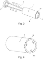
Figur 3 : Perspektivische Darstellung eines erfindungsgemäßen Wirkkörpers im Flug; -
Figur 4 : Perspektivische Darstellung eines erfindungsgemäßen Wirkkörpers im Ruhezustand; -
Figur 5 : Detaildarstellung eines ausgebrachten Bremsdeckels. -
Figur 1 zeigt einen erfindungsgemäßen Wurfkörper, welcher aus einem Gehäuse besteht und das Gehäuse einen Wirkkörper 1 aufweist. Der Wirkkörper 1 ist im Gehäuse angeordnet und enthält mindestens eine Effektladung, welche ausgebracht werden kann. Die Ausbringung der Effektladung kann durch Zerlegung oder Abbrand erfolgen. - Das Gehäuse des erfindungsgemäßen Wurfkörpers besteht aus mindestens zwei Gehäuseelementen 6, welche lösbar miteinander verbunden sind, um das Gehäuse zu bilden.
- In Längsrichtung des Wirkkörpers 1 wird der Wirkkörper in einer Richtung durch einen Bremsdeckel 4 begrenzt sowie in der anderen Richtung durch einen Deckel 3. An dem Wirkkörper 1 ist weiterhin eine Bremsschlaufe 5 vorgesehen, welche durch Löcher an dem Bremsdeckel 4 hindurchgeführt sind.
- Auf der Seite des Deckels 3 im Gehäuse des erfindungsgemäßen Wurfkörpers ist eine Ausstoßladung 7 vorgesehen. Die Ausstoßladung 7 ist in Flugrichtung 8 des Wurfkörpers angeordnet.
- Die Gehäuseelemente 6 sind lösbar miteinander verbunden, sodass bei Einwirkung einer Kraft auf die Gehäuseteile 6 die Verbindung gelöst wird und der Wirkkörper 1 aus dem Gehäuse des Wurfkörpers austreten kann.
- Zur Erzeugung einer solchen Kraft ist die Ausstoßladung 7 vorgesehen. Bei Zündung der Ausstoßladung 7 durch geeignete Mittel wird eine Kraft auf den Wirkkörper 1 ausgeübt und auch auf die Gehäuseelemente 6. Die Ausübung der Kraft auf die Gehäuseelemente 6 kann unmittelbar durch die Ausstoßladung erfolgen oder mittelbar durch die Kraftübertragung durch den Wirkkörper 1.
- Gleichzeitig zur Krafterzeugung sorgt die Ausstoßladung 7 für ein Anzünden der Effektladung im Wirkkörper 1. Dazu ist der Deckel 3 so gestaltet, dass die Ausstoßladung 7 die Effektladung anzünden kann, bevorzugterweise sind dazu Anzündbohrungen im Deckel 3 vorgesehen.
- Durch die von der Ausstoßladung 7 erzeugte Kraft wird nun der Wirkkörper 1 aus dem Wurfkörper entgegen der Flugrichtung 8 des Wurfkörpers ausgestoßen.
- Nach Ausstoßen des Wirkkörpers 1 unterliegt dieser nun den Umweltbedingungen während des Fluges des Wirkkörpers 1. Somit wirkt der während des Flugs vorhandene Luftwiderstand auf den Bremsdeckel 4 des Wirkkörpers 1. Da der Bremsdeckel 4 lösbar am Wirkkörper 1 befestigt ist, wird er nun entgegen der Flugrichtung 8 bewegt und durch die Durchführung der Bremsschlaufe 5 durch den Bremsdeckel 4 von der Bremsschlaufe 5 in einer Endposition gehalten.
-
Figur 2 zeigt dazu einen erfindungsgemäßen Wirkkörper 1 nach Ausbringung aus dem Wurfkörper. - Der erfindungsgemäße Wirkkörper 1 ist hierbei durch einen Mantel 9 umhüllt, wobei die Mantelenden durch den Bremsdeckel 4 und den Deckel 3 begrenzt werden. Der Mantel 9 sorgt hierbei, unter anderem, für die Verdämmung der Effektladung.
- Wirkt nun die genannte Luftreibung auf den Bremsdeckel 4 wird dieser entlang der Bremsschlaufe 5 entgegen der Flugrichtung bewegt. Zu sehen ist dies in
Figur 3 . - In der Endposition, in welcher der Bremsdeckel 4 von der Bremsschlaufe 5 gehalten wird, wirkt der Deckel nun wie ein kleiner Fallschirm durch die Luftreibung entgegen der Flugrichtung auf den Wirkkörper 1. Der Wirkkörper 1 wird somit gebremst. Dadurch wird dem eingangs erwähnten, negativen Effekt eines zu schnellen Aufschlags des Wirkkörpers 1 auf den Boden entgegengewirkt.
- Der Deckel 3 ist durch geeignete Verbindungselemente 10 fest mit dem Mantel 9 des Wirkkörpers 1 verbunden. Diese Verbindungselemente 10 können beispielsweise Stifte sein, welche in dafür vorgesehene Ausnehmungen im Mantel 9 des Wirkkörpers 1 eingreifen können. Ebenso sind aber auch Rastverbindungen oder Klebverbindungen denkbar.
- Um das Anzünden der Effektladung im Wirkköper 1 durch die Ausstoßladung 7 zu ermöglichen, können, wie in
Figur 4 gezeigt, Anzündbohrungen 11 vorgesehen sein. Mindestens eine solche Anzündbohrung 11 ist notwendig, um das Anzünden der Effektladung durch den Deckel 3 hindurch zu ermöglichen. -
Figur 5 zeigt dazu noch einmal die Durchführung 12 der Bremsschlaufe 5 durch den Bremsdeckel 4. Gezeigt sind hierbei zwei Löcher im Bremsdeckel 4. Es können hierbei auch mehrere Löcher vorgesehen sein. Bevorzugter Weise wird dann die Bremsschlaufe 5 mäanderförmig durch die Löcher im Bremsdeckel 4 hindurchgeführt. - Die Löcher im Bremsdeckel 4 können so gestaltet sein, dass sie eine gewisse Reibkraft auf die Bremsschlaufe 5 ausüben. Somit ist es möglich, den Bremsdeckel 4 an dem einen Ende des Mantels 9 zu halten und die benötigte Luftreibung zur Bewegung des Bremsdeckels 4 entlang der Bremsschlaufe 5 einzustellen.
- Die vorliegende Erfindung ist nicht auf die vorgenannten Merkmale beschränkt. Vielmehr sind weitere Ausführungsformen denkbar. So kann die Bremsschlaufe aus Gummi bestehen, die Ausstoßladung elektrisch wirken oder der Deckel brennbar gestaltet sein. Im Falle eines brennbaren Deckels sind jedoch Maßnahmen notwendig, um die Ausbringung der Effektladung in Flugrichtung zu verhindern und lediglich entgegen der Flugrichtung sicherzustellen.
-
- 1 -
- Wirkkörper
- 2 -
- Verbindung
- 3 -
- Deckel
- 4 -
- Bremsdeckel
- 5 -
- Bremsschlaufe
- 6 -
- Gehäuseelement
- 7 -
- Ausstoßladung
- 8 -
- Flugrichtung
- 9 -
- Mantel
- 10 -
- Verbindungselement
- 11 -
- Anzündbohrungen
- 12 -
- Durchführung von 5
Claims (15)
- Wirkkörper (1) zur Ausbringung mindestens einer Effektladung,
mit einem umlaufenden Mantel (9),
mit zwei Enden, welche durch den Mantel (9) gebildet werden,
mit einem Deckel (3), welcher eines der Enden abdeckt
dadurch gekennzeichnet,
dass das anderen Ende mit einem Bremsdeckel (4) abgedeckt werden kann,
dass der Bremsdeckel (4) mindestens ein Loch aufweist,
dass eine Bremsschlaufe (5) vorgesehen ist
und dass die Bremsschlaufe (5) durch das Loch des Bremsdeckels (4) hindurchgeführt ist. - Wirkkörper (1) nach Anspruch 1, dadurch gekennzeichnet, dass die Effektladung einen Raucheffekt erzeugen kann.
- Wirkkörper (1) nach Anspruch 1 oder 2, dadurch gekennzeichnet, dass der Deckel (3) durch Verbindungselemente (10) mit dem Wirkkörper (1) verbunden ist.
- Wirkkörper (1) nach Anspruch 3, dadurch gekennzeichnet, dass die Verbindungselemente (10) durch Verstiftung ausgeführt sind.
- Wirkkörper (1) nach einem der Ansprüche 1 bis 4, dadurch gekennzeichnet, dass die Bremsschlaufe (5) am Mantel (5) befestigt ist.
- Wirkkörper (1) nach einem der Ansprüche 1 bis 5, dadurch gekennzeichnet, dass der Deckel (3) mindestens eine Anzündbohrung (11) aufweist.
- Wirkkörper (1) nach Anspruch 6, dadurch gekennzeichnet, dass mehrere Anzündbohrungen (11) vorgesehen sind, welche radial umlaufend am Deckel (3) angeordnet sind.
- Wirkkörper (1) nach einem der Ansprüche 1 bis 7, dadurch gekennzeichnet, dass mehrere Löcher im Bremsdeckel (4) vorgesehen sind, sodass die Bremsschlaufe (5) durch die Löcher hindurchgeführt (12) wird.
- Wirkkörper (1) nach einem der Ansprüche 1 bis 8, dadurch gekennzeichnet, dass die Bremsschlaufe (5) aus einem gewebten Material besteht.
- Wirkkörper (1) nach einem der Ansprüche 1 bis 9, dadurch gekennzeichnet, dass der Bremsdeckel (4) beweglich entlang der Bremsschlaufe (5) gestaltet ist.
- Wurfkörper mit einem Gehäuse, bestehend aus mindestens zwei Gehäuselementen (6), dadurch gekennzeichnet, dass ein Wirkkörper (1) nach einem der Ansprüche 1 bis 10 im Gehäuse angeordnet ist.
- Wurfkörper nach Anspruch 11, dadurch gekennzeichnet, dass eine Ausstoßladung in Richtung des Deckels (3) im Gehäuse vorgesehen ist, welche eine Kraft auf den Wirkkörper ausüben kann und für die Anzündung der Effektladung sorgen kann.
- Wurfkörper nach Anspruch 11 oder 12, dadurch gekennzeichnet, dass mindestens zwei Gehäuseelemente (6) durch eine lösbare Verbindung (2) verbunden sind.
- Wurfkörper nach Anspruch 13, dadurch gekennzeichnet, dass die Kraft gleichzeitig auf den Wirkkörper und auf die Gehäuseelemente (6) wirkt, sodass die Verbindung (2) gelöst wird.
- Wurfkörper nach einem dem Ansprüche 11 bis 14, dadurch gekennzeichnet, dass der Wurfkörper aus einem Werfer ausgeworfen werden kann.
Applications Claiming Priority (1)
| Application Number | Priority Date | Filing Date | Title |
|---|---|---|---|
| DE102017121275.2A DE102017121275A1 (de) | 2017-09-14 | 2017-09-14 | Wirkkörper mit Bremsdeckel |
Publications (2)
| Publication Number | Publication Date |
|---|---|
| EP3457076A1 true EP3457076A1 (de) | 2019-03-20 |
| EP3457076B1 EP3457076B1 (de) | 2020-12-16 |
Family
ID=63363922
Family Applications (1)
| Application Number | Title | Priority Date | Filing Date |
|---|---|---|---|
| EP18190148.9A Active EP3457076B1 (de) | 2017-09-14 | 2018-08-22 | Wirkkörper mit bremsdeckel |
Country Status (2)
| Country | Link |
|---|---|
| EP (1) | EP3457076B1 (de) |
| DE (1) | DE102017121275A1 (de) |
Citations (6)
| Publication number | Priority date | Publication date | Assignee | Title |
|---|---|---|---|---|
| GB1605109A (en) * | 1976-02-23 | 1981-12-16 | Rheinmetall Gmbh | Projectile |
| GB2215014A (en) * | 1988-02-23 | 1989-09-13 | Charles Anthony Howard Knight | Short range projectile |
| DE4124655A1 (de) * | 1991-07-25 | 1993-01-28 | Rheinmetall Gmbh | Bremseinrichtung fuer submunition |
| US20070090174A1 (en) * | 2005-10-07 | 2007-04-26 | Goddard Richard V | Cellulose-based aerial delivery system and method of use |
| FR2960633A1 (fr) * | 2010-06-01 | 2011-12-02 | Nexter Munitions | Dispositif cargo a ouverture retardee |
| DE102010026641A1 (de) * | 2010-07-09 | 2012-01-12 | Diehl Bgt Defence Gmbh & Co. Kg | Nebelwurfkörper |
Family Cites Families (4)
| Publication number | Priority date | Publication date | Assignee | Title |
|---|---|---|---|---|
| US5398614A (en) * | 1994-06-10 | 1995-03-21 | The United States Of America As Represented By The Secretary Of The Army | Ram air inflated decelerator deployment flaps |
| US8480034B2 (en) * | 2009-05-29 | 2013-07-09 | Caylym Technologies International, Llc | Aerial delivery devices, systems and methods |
| US9138604B2 (en) * | 2008-07-28 | 2015-09-22 | The Boeing Company | Aerial delivery system |
| BR112017000923A2 (pt) * | 2014-07-16 | 2018-01-16 | The Skylife Company, Inc. | sistema e método para distribuição em massa de pacotes de abastecimento |
-
2017
- 2017-09-14 DE DE102017121275.2A patent/DE102017121275A1/de not_active Withdrawn
-
2018
- 2018-08-22 EP EP18190148.9A patent/EP3457076B1/de active Active
Patent Citations (6)
| Publication number | Priority date | Publication date | Assignee | Title |
|---|---|---|---|---|
| GB1605109A (en) * | 1976-02-23 | 1981-12-16 | Rheinmetall Gmbh | Projectile |
| GB2215014A (en) * | 1988-02-23 | 1989-09-13 | Charles Anthony Howard Knight | Short range projectile |
| DE4124655A1 (de) * | 1991-07-25 | 1993-01-28 | Rheinmetall Gmbh | Bremseinrichtung fuer submunition |
| US20070090174A1 (en) * | 2005-10-07 | 2007-04-26 | Goddard Richard V | Cellulose-based aerial delivery system and method of use |
| FR2960633A1 (fr) * | 2010-06-01 | 2011-12-02 | Nexter Munitions | Dispositif cargo a ouverture retardee |
| DE102010026641A1 (de) * | 2010-07-09 | 2012-01-12 | Diehl Bgt Defence Gmbh & Co. Kg | Nebelwurfkörper |
Also Published As
| Publication number | Publication date |
|---|---|
| DE102017121275A1 (de) | 2019-03-14 |
| EP3457076B1 (de) | 2020-12-16 |
Similar Documents
| Publication | Publication Date | Title |
|---|---|---|
| DE69703042T2 (de) | Nichtletales geschoss | |
| DE69512118T2 (de) | Geschoss, insbesondere nicht tötende Patrone | |
| DE69311805T2 (de) | Nebelwurfkörper | |
| WO2006086902A1 (de) | Geschoss | |
| DE69909719T2 (de) | Bremsvorrichtung für die Flugbahngeschwindigkeit eines Geschosses | |
| DE60005239T2 (de) | Bremsvorrichtung für die Flugbahngeschwindigkeit eines Geschosses | |
| DE60019110T2 (de) | Auslösevorrichtung | |
| DE10205043A1 (de) | Aus einem Rohr zu verschließender Flugkörper mit überkalibrigem Leitwerk | |
| EP0314875A2 (de) | Übungsgeschoss mit verkürzter Reichweite | |
| DE2547528C2 (de) | Artilleriegeschoß mit erhöhter Reichweite | |
| DE4419098A1 (de) | Feuerlöschgenerator mit einem Gehäuse | |
| DE2330045A1 (de) | Rakete zum abfeuern und verbreiten von reflektierendem material | |
| DE1956872A1 (de) | Pyrotechnischer Verzoegerungssatz | |
| DE2757806C2 (de) | Verbindungsvorrichtung zwischen zwei Stufen eines Flugkörpers mit Eigenantrieb | |
| EP3457076B1 (de) | Wirkkörper mit bremsdeckel | |
| DE1506101A1 (de) | Vorrichtung zur einwandfreien Entfaltung von Fallschirmen | |
| DE3904625C2 (de) | ||
| EP3036501B1 (de) | Pyrotechnische verzögerungseinrichtung für einen munitionszünder und mörsergranate mit einer derartigen verzögerungseinrichtung | |
| DE2446832C2 (de) | Zündvorrichtung für Werferrohre zur Zündung der Antriebsladung eines Projektils | |
| DE3640485C1 (en) | Bomblet (submunition) | |
| DE2506776C2 (de) | Geschoß | |
| DE102008032744B4 (de) | Zünder für ein Geschoss | |
| DE305133C (de) | ||
| WO2020260009A1 (de) | Geschoss | |
| DE1170714B (de) | Treibladung fuer Pulverraketen |
Legal Events
| Date | Code | Title | Description |
|---|---|---|---|
| PUAI | Public reference made under article 153(3) epc to a published international application that has entered the european phase |
Free format text: ORIGINAL CODE: 0009012 |
|
| STAA | Information on the status of an ep patent application or granted ep patent |
Free format text: STATUS: THE APPLICATION HAS BEEN PUBLISHED |
|
| AK | Designated contracting states |
Kind code of ref document: A1 Designated state(s): AL AT BE BG CH CY CZ DE DK EE ES FI FR GB GR HR HU IE IS IT LI LT LU LV MC MK MT NL NO PL PT RO RS SE SI SK SM TR |
|
| AX | Request for extension of the european patent |
Extension state: BA ME |
|
| STAA | Information on the status of an ep patent application or granted ep patent |
Free format text: STATUS: REQUEST FOR EXAMINATION WAS MADE |
|
| 17P | Request for examination filed |
Effective date: 20190913 |
|
| RBV | Designated contracting states (corrected) |
Designated state(s): AL AT BE BG CH CY CZ DE DK EE ES FI FR GB GR HR HU IE IS IT LI LT LU LV MC MK MT NL NO PL PT RO RS SE SI SK SM TR |
|
| STAA | Information on the status of an ep patent application or granted ep patent |
Free format text: STATUS: EXAMINATION IS IN PROGRESS |
|
| 17Q | First examination report despatched |
Effective date: 20200309 |
|
| GRAP | Despatch of communication of intention to grant a patent |
Free format text: ORIGINAL CODE: EPIDOSNIGR1 |
|
| STAA | Information on the status of an ep patent application or granted ep patent |
Free format text: STATUS: GRANT OF PATENT IS INTENDED |
|
| INTG | Intention to grant announced |
Effective date: 20200902 |
|
| GRAS | Grant fee paid |
Free format text: ORIGINAL CODE: EPIDOSNIGR3 |
|
| GRAA | (expected) grant |
Free format text: ORIGINAL CODE: 0009210 |
|
| STAA | Information on the status of an ep patent application or granted ep patent |
Free format text: STATUS: THE PATENT HAS BEEN GRANTED |
|
| AK | Designated contracting states |
Kind code of ref document: B1 Designated state(s): AL AT BE BG CH CY CZ DE DK EE ES FI FR GB GR HR HU IE IS IT LI LT LU LV MC MK MT NL NO PL PT RO RS SE SI SK SM TR |
|
| REG | Reference to a national code |
Ref country code: GB Ref legal event code: FG4D Free format text: NOT ENGLISH |
|
| REG | Reference to a national code |
Ref country code: DE Ref legal event code: R096 Ref document number: 502018003307 Country of ref document: DE |
|
| REG | Reference to a national code |
Ref country code: IE Ref legal event code: FG4D Free format text: LANGUAGE OF EP DOCUMENT: GERMAN |
|
| REG | Reference to a national code |
Ref country code: AT Ref legal event code: REF Ref document number: 1345992 Country of ref document: AT Kind code of ref document: T Effective date: 20210115 |
|
| REG | Reference to a national code |
Ref country code: NO Ref legal event code: CREP Representative=s name: JUERGEN KOHLSTEDDE, C/O THUL PATENTANWALTSGESELLSCHAFT |
|
| PG25 | Lapsed in a contracting state [announced via postgrant information from national office to epo] |
Ref country code: FI Free format text: LAPSE BECAUSE OF FAILURE TO SUBMIT A TRANSLATION OF THE DESCRIPTION OR TO PAY THE FEE WITHIN THE PRESCRIBED TIME-LIMIT Effective date: 20201216 Ref country code: RS Free format text: LAPSE BECAUSE OF FAILURE TO SUBMIT A TRANSLATION OF THE DESCRIPTION OR TO PAY THE FEE WITHIN THE PRESCRIBED TIME-LIMIT Effective date: 20201216 Ref country code: GR Free format text: LAPSE BECAUSE OF FAILURE TO SUBMIT A TRANSLATION OF THE DESCRIPTION OR TO PAY THE FEE WITHIN THE PRESCRIBED TIME-LIMIT Effective date: 20210317 |
|
| REG | Reference to a national code |
Ref country code: NL Ref legal event code: MP Effective date: 20201216 |
|
| REG | Reference to a national code |
Ref country code: NO Ref legal event code: T2 Effective date: 20201216 |
|
| PG25 | Lapsed in a contracting state [announced via postgrant information from national office to epo] |
Ref country code: BG Free format text: LAPSE BECAUSE OF FAILURE TO SUBMIT A TRANSLATION OF THE DESCRIPTION OR TO PAY THE FEE WITHIN THE PRESCRIBED TIME-LIMIT Effective date: 20210316 Ref country code: LV Free format text: LAPSE BECAUSE OF FAILURE TO SUBMIT A TRANSLATION OF THE DESCRIPTION OR TO PAY THE FEE WITHIN THE PRESCRIBED TIME-LIMIT Effective date: 20201216 Ref country code: SE Free format text: LAPSE BECAUSE OF FAILURE TO SUBMIT A TRANSLATION OF THE DESCRIPTION OR TO PAY THE FEE WITHIN THE PRESCRIBED TIME-LIMIT Effective date: 20201216 |
|
| PG25 | Lapsed in a contracting state [announced via postgrant information from national office to epo] |
Ref country code: HR Free format text: LAPSE BECAUSE OF FAILURE TO SUBMIT A TRANSLATION OF THE DESCRIPTION OR TO PAY THE FEE WITHIN THE PRESCRIBED TIME-LIMIT Effective date: 20201216 Ref country code: NL Free format text: LAPSE BECAUSE OF FAILURE TO SUBMIT A TRANSLATION OF THE DESCRIPTION OR TO PAY THE FEE WITHIN THE PRESCRIBED TIME-LIMIT Effective date: 20201216 |
|
| REG | Reference to a national code |
Ref country code: LT Ref legal event code: MG9D |
|
| PG25 | Lapsed in a contracting state [announced via postgrant information from national office to epo] |
Ref country code: LT Free format text: LAPSE BECAUSE OF FAILURE TO SUBMIT A TRANSLATION OF THE DESCRIPTION OR TO PAY THE FEE WITHIN THE PRESCRIBED TIME-LIMIT Effective date: 20201216 Ref country code: SK Free format text: LAPSE BECAUSE OF FAILURE TO SUBMIT A TRANSLATION OF THE DESCRIPTION OR TO PAY THE FEE WITHIN THE PRESCRIBED TIME-LIMIT Effective date: 20201216 Ref country code: PT Free format text: LAPSE BECAUSE OF FAILURE TO SUBMIT A TRANSLATION OF THE DESCRIPTION OR TO PAY THE FEE WITHIN THE PRESCRIBED TIME-LIMIT Effective date: 20210416 Ref country code: RO Free format text: LAPSE BECAUSE OF FAILURE TO SUBMIT A TRANSLATION OF THE DESCRIPTION OR TO PAY THE FEE WITHIN THE PRESCRIBED TIME-LIMIT Effective date: 20201216 Ref country code: SM Free format text: LAPSE BECAUSE OF FAILURE TO SUBMIT A TRANSLATION OF THE DESCRIPTION OR TO PAY THE FEE WITHIN THE PRESCRIBED TIME-LIMIT Effective date: 20201216 Ref country code: EE Free format text: LAPSE BECAUSE OF FAILURE TO SUBMIT A TRANSLATION OF THE DESCRIPTION OR TO PAY THE FEE WITHIN THE PRESCRIBED TIME-LIMIT Effective date: 20201216 Ref country code: CZ Free format text: LAPSE BECAUSE OF FAILURE TO SUBMIT A TRANSLATION OF THE DESCRIPTION OR TO PAY THE FEE WITHIN THE PRESCRIBED TIME-LIMIT Effective date: 20201216 |
|
| PG25 | Lapsed in a contracting state [announced via postgrant information from national office to epo] |
Ref country code: PL Free format text: LAPSE BECAUSE OF FAILURE TO SUBMIT A TRANSLATION OF THE DESCRIPTION OR TO PAY THE FEE WITHIN THE PRESCRIBED TIME-LIMIT Effective date: 20201216 |
|
| REG | Reference to a national code |
Ref country code: DE Ref legal event code: R097 Ref document number: 502018003307 Country of ref document: DE |
|
| PG25 | Lapsed in a contracting state [announced via postgrant information from national office to epo] |
Ref country code: IS Free format text: LAPSE BECAUSE OF FAILURE TO SUBMIT A TRANSLATION OF THE DESCRIPTION OR TO PAY THE FEE WITHIN THE PRESCRIBED TIME-LIMIT Effective date: 20210416 |
|
| PLBE | No opposition filed within time limit |
Free format text: ORIGINAL CODE: 0009261 |
|
| STAA | Information on the status of an ep patent application or granted ep patent |
Free format text: STATUS: NO OPPOSITION FILED WITHIN TIME LIMIT |
|
| PG25 | Lapsed in a contracting state [announced via postgrant information from national office to epo] |
Ref country code: IT Free format text: LAPSE BECAUSE OF FAILURE TO SUBMIT A TRANSLATION OF THE DESCRIPTION OR TO PAY THE FEE WITHIN THE PRESCRIBED TIME-LIMIT Effective date: 20201216 Ref country code: AL Free format text: LAPSE BECAUSE OF FAILURE TO SUBMIT A TRANSLATION OF THE DESCRIPTION OR TO PAY THE FEE WITHIN THE PRESCRIBED TIME-LIMIT Effective date: 20201216 |
|
| 26N | No opposition filed |
Effective date: 20210917 |
|
| PG25 | Lapsed in a contracting state [announced via postgrant information from national office to epo] |
Ref country code: DK Free format text: LAPSE BECAUSE OF FAILURE TO SUBMIT A TRANSLATION OF THE DESCRIPTION OR TO PAY THE FEE WITHIN THE PRESCRIBED TIME-LIMIT Effective date: 20201216 |
|
| PG25 | Lapsed in a contracting state [announced via postgrant information from national office to epo] |
Ref country code: ES Free format text: LAPSE BECAUSE OF FAILURE TO SUBMIT A TRANSLATION OF THE DESCRIPTION OR TO PAY THE FEE WITHIN THE PRESCRIBED TIME-LIMIT Effective date: 20201216 |
|
| REG | Reference to a national code |
Ref country code: DE Ref legal event code: R082 Ref document number: 502018003307 Country of ref document: DE Ref country code: DE Ref legal event code: R082 Ref document number: 502018003307 Country of ref document: DE Representative=s name: DREISS PATENTANWAELTE PARTG MBB, DE |
|
| PG25 | Lapsed in a contracting state [announced via postgrant information from national office to epo] |
Ref country code: SI Free format text: LAPSE BECAUSE OF FAILURE TO SUBMIT A TRANSLATION OF THE DESCRIPTION OR TO PAY THE FEE WITHIN THE PRESCRIBED TIME-LIMIT Effective date: 20201216 |
|
| REG | Reference to a national code |
Ref country code: DE Ref legal event code: R082 Ref document number: 502018003307 Country of ref document: DE Representative=s name: DREISS PATENTANWAELTE PARTG MBB, DE |
|
| REG | Reference to a national code |
Ref country code: CH Ref legal event code: PL |
|
| PG25 | Lapsed in a contracting state [announced via postgrant information from national office to epo] |
Ref country code: MC Free format text: LAPSE BECAUSE OF FAILURE TO SUBMIT A TRANSLATION OF THE DESCRIPTION OR TO PAY THE FEE WITHIN THE PRESCRIBED TIME-LIMIT Effective date: 20201216 |
|
| REG | Reference to a national code |
Ref country code: BE Ref legal event code: MM Effective date: 20210831 |
|
| PG25 | Lapsed in a contracting state [announced via postgrant information from national office to epo] |
Ref country code: LI Free format text: LAPSE BECAUSE OF NON-PAYMENT OF DUE FEES Effective date: 20210831 Ref country code: CH Free format text: LAPSE BECAUSE OF NON-PAYMENT OF DUE FEES Effective date: 20210831 |
|
| PG25 | Lapsed in a contracting state [announced via postgrant information from national office to epo] |
Ref country code: IS Free format text: LAPSE BECAUSE OF FAILURE TO SUBMIT A TRANSLATION OF THE DESCRIPTION OR TO PAY THE FEE WITHIN THE PRESCRIBED TIME-LIMIT Effective date: 20210416 Ref country code: LU Free format text: LAPSE BECAUSE OF NON-PAYMENT OF DUE FEES Effective date: 20210822 |
|
| PG25 | Lapsed in a contracting state [announced via postgrant information from national office to epo] |
Ref country code: IE Free format text: LAPSE BECAUSE OF NON-PAYMENT OF DUE FEES Effective date: 20210822 Ref country code: BE Free format text: LAPSE BECAUSE OF NON-PAYMENT OF DUE FEES Effective date: 20210831 |
|
| GBPC | Gb: european patent ceased through non-payment of renewal fee |
Effective date: 20220822 |
|
| PG25 | Lapsed in a contracting state [announced via postgrant information from national office to epo] |
Ref country code: CY Free format text: LAPSE BECAUSE OF FAILURE TO SUBMIT A TRANSLATION OF THE DESCRIPTION OR TO PAY THE FEE WITHIN THE PRESCRIBED TIME-LIMIT Effective date: 20201216 |
|
| PG25 | Lapsed in a contracting state [announced via postgrant information from national office to epo] |
Ref country code: HU Free format text: LAPSE BECAUSE OF FAILURE TO SUBMIT A TRANSLATION OF THE DESCRIPTION OR TO PAY THE FEE WITHIN THE PRESCRIBED TIME-LIMIT; INVALID AB INITIO Effective date: 20180822 |
|
| PG25 | Lapsed in a contracting state [announced via postgrant information from national office to epo] |
Ref country code: GB Free format text: LAPSE BECAUSE OF NON-PAYMENT OF DUE FEES Effective date: 20220822 |
|
| PG25 | Lapsed in a contracting state [announced via postgrant information from national office to epo] |
Ref country code: MK Free format text: LAPSE BECAUSE OF FAILURE TO SUBMIT A TRANSLATION OF THE DESCRIPTION OR TO PAY THE FEE WITHIN THE PRESCRIBED TIME-LIMIT Effective date: 20201216 |
|
| PG25 | Lapsed in a contracting state [announced via postgrant information from national office to epo] |
Ref country code: TR Free format text: LAPSE BECAUSE OF FAILURE TO SUBMIT A TRANSLATION OF THE DESCRIPTION OR TO PAY THE FEE WITHIN THE PRESCRIBED TIME-LIMIT Effective date: 20201216 |
|
| PG25 | Lapsed in a contracting state [announced via postgrant information from national office to epo] |
Ref country code: MT Free format text: LAPSE BECAUSE OF FAILURE TO SUBMIT A TRANSLATION OF THE DESCRIPTION OR TO PAY THE FEE WITHIN THE PRESCRIBED TIME-LIMIT Effective date: 20201216 |
|
| REG | Reference to a national code |
Ref country code: AT Ref legal event code: MM01 Ref document number: 1345992 Country of ref document: AT Kind code of ref document: T Effective date: 20230822 |
|
| PG25 | Lapsed in a contracting state [announced via postgrant information from national office to epo] |
Ref country code: AT Free format text: LAPSE BECAUSE OF NON-PAYMENT OF DUE FEES Effective date: 20230822 |
|
| PG25 | Lapsed in a contracting state [announced via postgrant information from national office to epo] |
Ref country code: AT Free format text: LAPSE BECAUSE OF NON-PAYMENT OF DUE FEES Effective date: 20230822 |
|
| PGFP | Annual fee paid to national office [announced via postgrant information from national office to epo] |
Ref country code: DE Payment date: 20250820 Year of fee payment: 8 |
|
| PGFP | Annual fee paid to national office [announced via postgrant information from national office to epo] |
Ref country code: NO Payment date: 20250826 Year of fee payment: 8 |
|
| PGFP | Annual fee paid to national office [announced via postgrant information from national office to epo] |
Ref country code: FR Payment date: 20250828 Year of fee payment: 8 |
|
| PGFP | Annual fee paid to national office [announced via postgrant information from national office to epo] |
Ref country code: AT Payment date: 20260410 Year of fee payment: 5 |