EP3450123B1 - Machine à couper en tranche munie d'un support de coupe - Google Patents
Machine à couper en tranche munie d'un support de coupe Download PDFInfo
- Publication number
- EP3450123B1 EP3450123B1 EP17188565.0A EP17188565A EP3450123B1 EP 3450123 B1 EP3450123 B1 EP 3450123B1 EP 17188565 A EP17188565 A EP 17188565A EP 3450123 B1 EP3450123 B1 EP 3450123B1
- Authority
- EP
- European Patent Office
- Prior art keywords
- cut
- holder
- carriage
- slicing machine
- machine according
- Prior art date
- Legal status (The legal status is an assumption and is not a legal conclusion. Google has not performed a legal analysis and makes no representation as to the accuracy of the status listed.)
- Active
Links
- 239000000463 material Substances 0.000 claims description 117
- 239000002184 metal Substances 0.000 claims description 3
- 238000011161 development Methods 0.000 description 3
- 230000018109 developmental process Effects 0.000 description 3
- 230000002441 reversible effect Effects 0.000 description 3
- 238000009434 installation Methods 0.000 description 2
- 101100390736 Danio rerio fign gene Proteins 0.000 description 1
- 101100390738 Mus musculus Fign gene Proteins 0.000 description 1
- 208000027418 Wounds and injury Diseases 0.000 description 1
- 230000006378 damage Effects 0.000 description 1
- 208000014674 injury Diseases 0.000 description 1
- 238000000465 moulding Methods 0.000 description 1
Images


Classifications
-
- B—PERFORMING OPERATIONS; TRANSPORTING
- B26—HAND CUTTING TOOLS; CUTTING; SEVERING
- B26D—CUTTING; DETAILS COMMON TO MACHINES FOR PERFORATING, PUNCHING, CUTTING-OUT, STAMPING-OUT OR SEVERING
- B26D7/00—Details of apparatus for cutting, cutting-out, stamping-out, punching, perforating, or severing by means other than cutting
- B26D7/06—Arrangements for feeding or delivering work of other than sheet, web, or filamentary form
- B26D7/0616—Arrangements for feeding or delivering work of other than sheet, web, or filamentary form by carriages, e.g. for slicing machines
-
- B—PERFORMING OPERATIONS; TRANSPORTING
- B26—HAND CUTTING TOOLS; CUTTING; SEVERING
- B26D—CUTTING; DETAILS COMMON TO MACHINES FOR PERFORATING, PUNCHING, CUTTING-OUT, STAMPING-OUT OR SEVERING
- B26D3/00—Cutting work characterised by the nature of the cut made; Apparatus therefor
- B26D3/16—Cutting rods or tubes transversely
- B26D3/162—Cutting rods or tubes transversely cutting tubes obliquely
-
- B—PERFORMING OPERATIONS; TRANSPORTING
- B26—HAND CUTTING TOOLS; CUTTING; SEVERING
- B26D—CUTTING; DETAILS COMMON TO MACHINES FOR PERFORATING, PUNCHING, CUTTING-OUT, STAMPING-OUT OR SEVERING
- B26D5/00—Arrangements for operating and controlling machines or devices for cutting, cutting-out, stamping-out, punching, perforating, or severing by means other than cutting
- B26D5/08—Means for actuating the cutting member to effect the cut
- B26D5/086—Electric, magnetic, piezoelectric, electro-magnetic means
-
- B—PERFORMING OPERATIONS; TRANSPORTING
- B26—HAND CUTTING TOOLS; CUTTING; SEVERING
- B26D—CUTTING; DETAILS COMMON TO MACHINES FOR PERFORATING, PUNCHING, CUTTING-OUT, STAMPING-OUT OR SEVERING
- B26D7/00—Details of apparatus for cutting, cutting-out, stamping-out, punching, perforating, or severing by means other than cutting
- B26D7/26—Means for mounting or adjusting the cutting member; Means for adjusting the stroke of the cutting member
- B26D7/2628—Means for adjusting the position of the cutting member
- B26D7/265—Journals, bearings or supports for positioning rollers or cylinders relatively to each other
-
- B—PERFORMING OPERATIONS; TRANSPORTING
- B26—HAND CUTTING TOOLS; CUTTING; SEVERING
- B26D—CUTTING; DETAILS COMMON TO MACHINES FOR PERFORATING, PUNCHING, CUTTING-OUT, STAMPING-OUT OR SEVERING
- B26D1/00—Cutting through work characterised by the nature or movement of the cutting member or particular materials not otherwise provided for; Apparatus or machines therefor; Cutting members therefor
- B26D1/01—Cutting through work characterised by the nature or movement of the cutting member or particular materials not otherwise provided for; Apparatus or machines therefor; Cutting members therefor involving a cutting member which does not travel with the work
- B26D1/12—Cutting through work characterised by the nature or movement of the cutting member or particular materials not otherwise provided for; Apparatus or machines therefor; Cutting members therefor involving a cutting member which does not travel with the work having a cutting member moving about an axis
- B26D1/14—Cutting through work characterised by the nature or movement of the cutting member or particular materials not otherwise provided for; Apparatus or machines therefor; Cutting members therefor involving a cutting member which does not travel with the work having a cutting member moving about an axis with a circular cutting member, e.g. disc cutter
- B26D1/143—Cutting through work characterised by the nature or movement of the cutting member or particular materials not otherwise provided for; Apparatus or machines therefor; Cutting members therefor involving a cutting member which does not travel with the work having a cutting member moving about an axis with a circular cutting member, e.g. disc cutter rotating about a stationary axis
- B26D1/15—Cutting through work characterised by the nature or movement of the cutting member or particular materials not otherwise provided for; Apparatus or machines therefor; Cutting members therefor involving a cutting member which does not travel with the work having a cutting member moving about an axis with a circular cutting member, e.g. disc cutter rotating about a stationary axis with vertical cutting member
-
- B—PERFORMING OPERATIONS; TRANSPORTING
- B26—HAND CUTTING TOOLS; CUTTING; SEVERING
- B26D—CUTTING; DETAILS COMMON TO MACHINES FOR PERFORATING, PUNCHING, CUTTING-OUT, STAMPING-OUT OR SEVERING
- B26D1/00—Cutting through work characterised by the nature or movement of the cutting member or particular materials not otherwise provided for; Apparatus or machines therefor; Cutting members therefor
- B26D1/01—Cutting through work characterised by the nature or movement of the cutting member or particular materials not otherwise provided for; Apparatus or machines therefor; Cutting members therefor involving a cutting member which does not travel with the work
- B26D1/12—Cutting through work characterised by the nature or movement of the cutting member or particular materials not otherwise provided for; Apparatus or machines therefor; Cutting members therefor involving a cutting member which does not travel with the work having a cutting member moving about an axis
- B26D1/14—Cutting through work characterised by the nature or movement of the cutting member or particular materials not otherwise provided for; Apparatus or machines therefor; Cutting members therefor involving a cutting member which does not travel with the work having a cutting member moving about an axis with a circular cutting member, e.g. disc cutter
- B26D1/143—Cutting through work characterised by the nature or movement of the cutting member or particular materials not otherwise provided for; Apparatus or machines therefor; Cutting members therefor involving a cutting member which does not travel with the work having a cutting member moving about an axis with a circular cutting member, e.g. disc cutter rotating about a stationary axis
- B26D1/153—Cutting through work characterised by the nature or movement of the cutting member or particular materials not otherwise provided for; Apparatus or machines therefor; Cutting members therefor involving a cutting member which does not travel with the work having a cutting member moving about an axis with a circular cutting member, e.g. disc cutter rotating about a stationary axis with inclined cutting member
-
- B—PERFORMING OPERATIONS; TRANSPORTING
- B26—HAND CUTTING TOOLS; CUTTING; SEVERING
- B26D—CUTTING; DETAILS COMMON TO MACHINES FOR PERFORATING, PUNCHING, CUTTING-OUT, STAMPING-OUT OR SEVERING
- B26D2210/00—Machines or methods used for cutting special materials
- B26D2210/02—Machines or methods used for cutting special materials for cutting food products, e.g. food slicers
-
- B—PERFORMING OPERATIONS; TRANSPORTING
- B26—HAND CUTTING TOOLS; CUTTING; SEVERING
- B26D—CUTTING; DETAILS COMMON TO MACHINES FOR PERFORATING, PUNCHING, CUTTING-OUT, STAMPING-OUT OR SEVERING
- B26D7/00—Details of apparatus for cutting, cutting-out, stamping-out, punching, perforating, or severing by means other than cutting
- B26D7/26—Means for mounting or adjusting the cutting member; Means for adjusting the stroke of the cutting member
- B26D7/2614—Means for mounting the cutting member
- B26D7/2621—Means for mounting the cutting member for circular cutters
Definitions
- the invention relates to a disk cutting machine for cutting disks from, in particular, strand-shaped material to be cut, preferably foodstuffs, with a cutting device which comprises a circular knife rotating in a cutting plane about an axis of rotation perpendicular to the cutting plane, with a carriage which has a carriage plate in a carriage plane perpendicular to the cutting plane and carries at least one slide wall, which protrudes from the slide plane, and with a cutting material holder, which has a support for receiving the cutting material to be cut and which is designed to bring the cutting material to the circular knife at an angle ⁇ ⁇ 90 ° relative to the cutting plane, whereby the cutting material holder has a fastening device for precisely fitting fastening of the cutting material holder to the slide wall, the fastening device being designed in such a way that the cut material holder fixes in a defined, reproducible position relative to the slide wall can be ert, and that the fastening device allows a reversible, reproducible in terms of the relative position of the
- Such a disk cutting machine is known from the DE 10 37 909 B or the DE 14 33 283 U .
- Disc cutting machines of this type enable an oblique cut of the material to be cut.
- the material to be cut can be separated at an angle ⁇ , approximately at 45 °, to the plane perpendicular to the longitudinal direction of the material to be cut.
- oval slices can be cut off on such a slice cutting machine, which have a larger area than approximately circular slices.
- the material to be cut could also be cut obliquely without a material holder by placing the material to be cut on the slide plate or holding it at an angle.
- a disadvantage of this solution is that the use of the cutting material holder described there is limited to only a few types of disk cutting machines. For example, it can due to a lack of free space, the clamp is often not fixed to the slide plate as intended.
- the object of the invention is to improve a generic disk cutting machine inexpensively and with readily available technical means, in particular to offer a reproducible, reliable and versatile, diagonally cutting electrically operated disk cutting machine, the angle at which the disk cutting takes place and so that the shape and size of the cut slices can be adjusted.
- a generic electrically operated disc cutting machine in which the fastening device is designed in such a way that it fixes the material holder in different, selectable relative positions of the material holder and the carriage wall, so that different angles are set under which the material to be cut can be brought to the circular knife at an angle to the axis of rotation.
- the material holder can thus be fixed to the side wall of the disc cutting machine with the required accuracy and reproducibility. A certain geometric configuration of the slide plate is not necessary for this.
- the material holder can essentially be fixed to any existing disc cutting machine, provided that the carriage has a carriage wall.
- any existing disk cutting machine can easily be retrofitted to a disk cutting machine according to the invention or converted into one. It is generally not necessary to adapt the disk cutting machine further before attaching the material holder.
- the hygiene requirements which are particularly high in the area of food processing, can be met relatively easily, since the installation and removal of the material holder is particularly easy and reversible.
- the uninstalled sliced food holder can be cleaned and / or disinfected separately from the remaining disk cutting machine, for example in a dishwasher, which makes compliance with the high hygiene requirements significantly easier.
- the fastening device can have a clamping section for reversible and reproducible fastening, in particular via a press connection by means of a clamping screw, preferably a knurled screw.
- a clamping screw preferably a knurled screw.
- Installation and / or deinstallation is particularly simple in embodiments of the invention in which the cutting material holder can be fastened to the slide wall without tools.
- the clamping screw mentioned above can have an actuating head, for example.
- the material to be cut in particular the support for receiving the material to be cut, has one or more devices for fixing the material to be cut relative to the support of the material to be cut, for example in the form of one or more counterholders.
- the material to be cut can thus be held securely in the material holder.
- a bevel cutter Comparable to a vertical cutter, a bevel cutter also cuts a slice from the factory at a right angle. In contrast to the vertical cutter, however, the axis of rotation of his circular knife and thus also his slide plate are tilted against the horizontal. If a material holder is now mounted on a bevel cutter - and thus potentially further increases the inclination of the material to be cut against the horizontal - the fixation devices can prevent the material from tipping over. Occupational safety can also be thereby significantly improve that for an oblique cut the material to be cut no longer needs to be held manually or that a user is not "tempted" to hold the material to be cut by hand.
- the sled often has a plurality of sled walls, in particular a sled front wall located in the pushing direction and a sled rear wall located in the pushing direction.
- the fastening device can then be attached to a rear wall of the carriage arranged in the cutting direction behind the axis of rotation for the purpose of a precisely fitting fastening of the material to be cut.
- compressive forces instead of tensile forces are to be dissipated via the fastening device into the slide wall during the slice cut.
- the lateral hold of a typical strand-like material to be cut can be improved in that the support of the material to be cut is designed to be gutter-shaped, in particular with a U-shaped or V-shaped cross section, for receiving the material to be cut.
- the cutting material holder or at least its support for receiving the cutting material to be cut can be made of shaped sheet metal in particularly simple and inexpensive embodiments of the invention.
- the cutting material holder or at least its support can be formed in one piece in preferred developments of these embodiments.
- the fastening device is rigidly connected to the rest of the material holder, in particular to the support.
- the support for receiving the material to be cut can have at least one movable wall section which is adjustable, in particular tiltable and / or displaceable. Then the support can be adapted to the geometry of the material to be cut.
- the movable wall section can be designed such that the geometry of the support can in each case be adapted to the cross section of the material to be cut currently to be cut.
- a further improvement can be achieved by embodiments of the invention in which the material holder has a fixing device for fixing an element of the slide, in particular a remnant holder.
- the carriage typically has further elements, such as a remnant holder, which are not necessarily required or at least not used when the cutting material holder is used.
- these further elements can be fixed in such a way that they do not hinder the operation of the disk cutting machine with the material holder.
- the remnant holder can be fixed when it is in a certain position on a rail for displacing the remnant holder.
- This can be achieved in particular by designing the Reach fixation device.
- the fixing device can, for example, have a tension arm, by means of which the remnant holder can be held in a desired position.
- the disk cutting machine according to the invention can be designed as a vertical cutter or as a bevel cutter.
- both vertical and bevel cutters can be equipped and used with the embodiments of cutting material holders described above and below, even if a specific embodiment of a cutting material holder should only be described (or useful) in connection with a type of disk cutting machine ,
- the cutting material holder according to the invention can be used in a large number of disc cutting machines, it is even conceivable to use the cutting material holder separately from a specific disc cutting machine.
- the cutting material holder can be used as an in particular modular accessory part and / or as a retrofit part.
- the cutting material holder can alternatively or additionally be aligned by an angle ⁇ in a plane perpendicular to the cutting plane E, in the case of a vertical cutter in an at least substantially horizontal plane.
- an inclined cut of the material to be cut can also be made by inclining it relative to the circular knife, for example in the at least substantially horizontal plane.
- an adjustable and / or adjustable joint can be provided on the fastening device, with which the support is rotatable relative to the fastening device in the at least substantially horizontal plane.
- the material to be cut only comes into contact with flat or at least substantially flat surfaces, in particular of the material to be cut.
- Other surfaces and / or other elements such as screws, gaps etc. can be configured or positioned, preferably already constructively, away from the intended location of the material to be cut.
- the Fig. 1 shows a first embodiment of an electrically operated disk cutting machine 10 according to the invention for
- the disk cutting machine 10 is designed as a vertical cutter.
- a cutting device 12 which comprises a circular knife 16 rotating in a cutting plane E about an axis of rotation X perpendicular to the cutting plane E and driven by a knife motor 14 .
- the slice cut and in particular the knife motor 14 are controlled and monitored by means of an input and control unit 18 .
- the disk cutting machine 10 has a slide 20 which carries a slide plate 22 in a slide plane S perpendicular to the cutting plane E and at least one slide wall 24 which projects out of the slide plane E, and a cutting material holder 26 which has a support 28 with support side surfaces 29 for receiving of the material to be cut and which is designed to bring the material to be cut at an angle ⁇ ⁇ 90 ° relative to the cutting plane E to the circular knife 16.
- the cutting material holder 26 has a fastening device 30 for a precisely fitting fastening of the cutting material holder 26 to the slide wall 24.
- the slide 20 is moved along a cutting direction R.
- the carriage wall 24, on which the material holder 26 according to the Fig. 1 is fixed viewed in the cutting direction R, a slide rear wall of the slide 20.
- FIGS. 2 and 3 show perspective representations of the carriage 20 with the arranged on the carriage wall 24 Cutter holder 26 the Fig. 1 , Fig. 3 represents the carriage 20 in a perspective view of the circular knife 16 (see Fig. 1 ) seen from here Fig. 3 for the sake of illustration only part of the slide wall 24.
- the fastening device 30 has a clamping section 32 with a clamping screw 34 designed as a knurled screw.
- the cutting material holder 26 can be fastened reversibly and reproducibly to the slide wall 24, in particular clamped thereon by means of a press connection.
- a corresponding actuation or rotation of an actuating head 36 of the clamping screw 34 is sufficient for this purpose.
- the material holder 26 can thus be attached to the slide wall 24 without tools.
- the fastening device 30 can thus be reversibly released from the slide wall 24 by means of the clamping screw 34 and fixed to the latter.
- the fastening device 30 can be fixed at defined, reproducible positions relative to the slide wall 24.
- the defined, reproducible position relative to the slide wall 24 is a position at which the slide wall 24 forms an engagement protection which rises vertically from the slide wall 24. This vertical elevation of the sled wall also serves as a vertical stop for the fastening device 30.
- the angle ⁇ ie the angle of inclination of the support 28 and thus also the cutting angle at which slices are separated from the material to be cut, can be set by depending on the desired inclination of the support 28 Fastening device 30 is fixed at different positions of the slide wall 24.
- the material holder 26 is arranged flush with the knife-side edge of the slide 20.
- the support side surfaces 29 are beveled in relation to a support base 38 of the support 28 in accordance with the angle ⁇ or values typically to be expected for this.
- Fig. 4 provides the material holder 26 of the Fig.1 perspective in a view from below.
- its support 28 is shaped as a sheet, in particular as a sheet metal.
- the support 28 is shaped like a groove. Its trough-shaped, in particular U-shaped, cross section is produced by means of press molding. The distance and the lateral angle of inclination of the two side surfaces 29 of the support 28 are matched to the dimensions of the material to be typically expected.
- the fastening device 30 is rigidly connected to the rest of the material holder 26. Overall, the material holder 26 is thus formed in one piece.
- the fastening device 30 has fastening recesses 40 in the form of slots in the region of its clamping section 32, which provide a precisely fitting fastening of the cut material holder 26 to the slide wall 24 (see Fig. 1 ) enable.
- Fig. 5 shows a perspective view of a further embodiment of the disk cutting machine according to the invention 10 ' with a slide 20', on the slide wall 24 'of which a cutting material holder 26' is installed.
- the carriage 20 ' also has a carriage plate 22' .
- the disk cutting machine 10 'and in particular its cutting material holder 26' largely corresponds to the disk cutting machine 10 Fig. 1 , so that only special features and differences of this embodiment are to be described below.
- the disk cutting machine 10 ' is designed as a bevel cutter.
- its slide 20 ' has Fig. 1 a residue holder 42 ' , which is arranged on a carriage front wall 44' of the carriage 20 '.
- the material holder 26 ' has an element holder 46' .
- This comprises a length-adjustable, in particular telescopic, element holder arm 48 '.
- the element holder 46 ' forms a fixing device for fixing the residual holder 42'. It fixes the remnant holder 42 'when the cutting material holder 26' is mounted in a specific, predeterminable rest position, in this embodiment in particular essentially vertically erected.
- the element holder 46 ' supports the residue holder 42' via its element holder arm 48 'on the slide wall 24'.
- the element holder 46 ' can be adapted to different disc cutting machines by changing the length of the element holder arm 48'.
- Fig. 6 shows the carriage 20 'with the material holder 26' in a perspective side view with a view of the circular knife of the disk cutting machine 10 ' Fig. 5 ,
- the slide 20 ' has a rail 50' on which the residue holder 42 'is slidably arranged.
- the residue holder 42 ' can thus be moved into a position suitable for fixing by the element holder 46'.
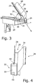
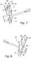
- Figures 7 and 8 the material holder 26 'of the embodiment of the disk cutting machine 10' according to the Fig. 5 as a perspective side view (see Fig. 7 ) and as a perspective view from above (see Fig. 8 ).
- the support 28 'of the product holder 26' has two support side surfaces 29 ' , one of which is designed as a movable wall section 52' .
- the movable wall section 52 ' is designed to be tiltable and thus adjustable by means of a wall adjustment 54' designed as a fixable hinge.
- the geometry of the support 28 'can thus be adapted to the material to be cut, in particular its cross section.
- counterholders 58' also extend through one of the support side surfaces 29 '.
- the counterholders can also be pushed up and down in the side surface through openings. This is done by having the handle on the back (in the case of the embodiment of Fig. 5 the axis G 'is shown) shifts accordingly.
Landscapes
- Life Sciences & Earth Sciences (AREA)
- Forests & Forestry (AREA)
- Engineering & Computer Science (AREA)
- Mechanical Engineering (AREA)
- Food-Manufacturing Devices (AREA)
- Details Of Cutting Devices (AREA)
- Sawing (AREA)
Claims (13)
- Machine à couper en tranche à fonctionnement électrique (10, 10') pour la coupe de tranches de produit à couper en particulier en forme de boudin, de préférence aliment, avec un dispositif de coupe (12), qui comprend un couteau circulaire (16) entraîné par un moteur de couteau (14), tournant dans un plan de coupe (E) autour d'un axe de rotation (X) perpendiculaire au plan de coupe (E), avec un chariot (20, 20') qui porte une plaque de chariot (22, 22') dans un plan de chariot (S) perpendiculaire au plan de coupe (E) et au moins une paroi de chariot (24, 24'), qui dépasse du plan de chariot (S), et avec un support de coupe (26, 26'), qui présente un élément d'appui (28, 28') pour la réception du produit à couper et qui est réalisé pour approcher le produit à couper du couteau circulaire (16) selon un angle α < 90° par rapport au plan de coupe (E), dans laquelle le support de coupe (26, 26') présente un dispositif de fixation (30) pour la fixation sur mesure du support de coupe (26, 26') au niveau de la paroi de chariot (24, 24'), dans laquelle le dispositif de fixation (30) est conçu de sorte que le support de coupe (26, 26') peut être fixé dans une position définie reproductible par rapport à la paroi de chariot (24, 24'), et que le dispositif de fixation (30) permet une fixation réversible du support de coupe (26, 26'), reproductible à l'état de fonctionnement en ce qui concerne la position relative du support de coupe (26, 26') et de la paroi de chariot (24, 24') au niveau de la paroi de chariot (24, 24') ainsi qu'un démontage du support de coupe (26, 26') de la paroi de chariot (24, 24'),
caractérisée en ce que
le dispositif de fixation (30) est conçu de sorte qu'il permet une fixation du support de coupe (26, 26') dans différentes positions relatives sélectionnables du support de coupe (26, 26') et de la paroi de chariot (24, 24') de sorte que différents angles (α) peuvent être réglés, selon lesquels le produit à couper peut être approché du couteau circulaire (16) obliquement par rapport à l'axe de rotation (X). - Machine à couper en tranche selon la revendication 1, caractérisée en ce que le dispositif de fixation (30) comprend une section de serrage (32) pour la fixation réversible et reproductible, en particulier par le biais d'un assemblage par compression au moyen d'une vis de serrage (34), de préférence d'une vis moletée.
- Machine à couper en tranche selon l'une quelconque des revendications précédentes, caractérisée en ce que le support de coupe (26, 26') peut être fixé sans outil au niveau de la paroi de chariot (24, 24').
- Machine à couper en tranche selon l'une quelconque des revendications précédentes, caractérisée en ce que le support de coupe (26, 26'), en particulier l'élément d'appui (28, 28') pour la réception du produit à couper, présente un ou plusieurs dispositifs pour la fixation du produit à couper par rapport à la plaque de chariot (22, 22'), par exemple sous forme d'un ou plusieurs contre-support (58').
- Machine à couper en tranche selon l'une quelconque des revendications précédentes, caractérisée en ce que le dispositif de fixation (30) est monté pour la fixation sur mesure du support de coupe (26, 26') au niveau d'une paroi arrière de chariot (paroi de chariot 24, 24') agencée dans la direction de coupe (S) derrière l'axe de rotation (X).
- Machine à couper en tranche selon l'une quelconque des revendications précédentes, caractérisée en ce que l'élément d'appui (28, 28') du support de coupe (26, 26') pour la réception du produit à couper est réalisé en forme de gouttière, en particulier avec une section transversale en forme de U ou en forme de V.
- Machine à couper en tranche selon l'une quelconque des revendications précédentes, caractérisée en ce que le support de coupe (26, 26') ou au moins son élément d'appui (28, 28') pour la réception du produit à couper est fabriqué en tôle moulée.
- Machine à couper en tranche selon la revendication 7, caractérisée en ce que le support de coupe (26, 26') ou au moins son élément d'appui (28, 28') est réalisé d'un seul tenant.
- Machine à couper en tranche selon l'une quelconque des revendications 1 à 7, caractérisée en ce que l'élément d'appui (28, 28') pour la réception du produit à couper présente au moins une section de paroi mobile (52'), qui est réalisée de manière ajustable, en particulier basculante et/ou déplaçable.
- Machine à couper en tranche selon la revendication 9, caractérisée en ce que la section de paroi mobile (52') est conçue de sorte que la géométrie de l'élément d'appui (28, 28') peut être adaptée respectivement à la section transversale du produit à couper actuellement.
- Machine à couper en tranche selon l'une quelconque des revendications précédentes, caractérisée en ce que le support de coupe (26, 26') présente un dispositif de fixation, en particulier un support d'élément (46'), pour la fixation d'un élément du chariot, en particulier d'un support de restes (42').
- Machine à couper en tranche selon la revendication 11, caractérisée en ce que le support de restes (42') peut être fixé, lorsqu'il se trouve dans une position déterminée sur un rail (50') pour le déplacement du support de restes (42'), en particulier par une configuration correspondante du dispositif de fixation, en particulier du support d'élément (46').
- Machine à couper en tranche selon l'une quelconque des revendications précédentes, caractérisée en ce que la machine à couper en tranche (10, 10') est réalisée en tant que trancheuse verticale ou en tant que trancheuse oblique.
Priority Applications (2)
| Application Number | Priority Date | Filing Date | Title |
|---|---|---|---|
| EP17188565.0A EP3450123B1 (fr) | 2017-08-30 | 2017-08-30 | Machine à couper en tranche munie d'un support de coupe |
| US16/114,239 US10618189B2 (en) | 2017-08-30 | 2018-08-28 | Disc cutting machine having a holder for material to be cut |
Applications Claiming Priority (1)
| Application Number | Priority Date | Filing Date | Title |
|---|---|---|---|
| EP17188565.0A EP3450123B1 (fr) | 2017-08-30 | 2017-08-30 | Machine à couper en tranche munie d'un support de coupe |
Publications (2)
| Publication Number | Publication Date |
|---|---|
| EP3450123A1 EP3450123A1 (fr) | 2019-03-06 |
| EP3450123B1 true EP3450123B1 (fr) | 2020-01-15 |
Family
ID=59846344
Family Applications (1)
| Application Number | Title | Priority Date | Filing Date |
|---|---|---|---|
| EP17188565.0A Active EP3450123B1 (fr) | 2017-08-30 | 2017-08-30 | Machine à couper en tranche munie d'un support de coupe |
Country Status (2)
| Country | Link |
|---|---|
| US (1) | US10618189B2 (fr) |
| EP (1) | EP3450123B1 (fr) |
Families Citing this family (4)
| Publication number | Priority date | Publication date | Assignee | Title |
|---|---|---|---|---|
| EP3498441B1 (fr) * | 2017-12-18 | 2019-10-23 | Bizerba SE & Co. KG | Machine à découper des aliments |
| US20210187773A1 (en) * | 2018-05-31 | 2021-06-24 | Hollymatic Corporation | Method and system to control, automate, monitor, and shut down a deli slicer |
| CN113119187B (zh) * | 2021-04-19 | 2022-09-23 | 日照同力橡塑有限公司 | 一种化学橡胶产品的裁切系统 |
| CN116786220B (zh) * | 2023-08-22 | 2023-11-07 | 黑龙江省农业科学院经济作物研究所 | 一种用于马铃薯病原菌检测的破碎机 |
Family Cites Families (25)
| Publication number | Priority date | Publication date | Assignee | Title |
|---|---|---|---|---|
| DE1433283U (fr) * | 1900-01-01 | |||
| AT111197B (de) * | 1925-05-27 | 1928-11-10 | Cornelis Franciscus Mar Berkel | Aufschnittmaschine mit selbsttätig periodisch verstellbarem Fleischtisch. |
| US2187312A (en) | 1938-08-09 | 1940-01-16 | Goodlake Clyde | Meat table |
| DE935347C (de) * | 1953-11-06 | 1955-11-17 | Bizerba Waagenfabrik Wilhelm K | Aufschnittschneidmaschine |
| DE1037909B (de) * | 1957-08-30 | 1958-08-28 | Friedrich Graff Fa | Scheibenschneidmaschine |
| US4379416A (en) * | 1977-06-01 | 1983-04-12 | Brain Dust Patents Establishment | Food-slicing machine and method |
| US4397206A (en) * | 1980-11-03 | 1983-08-09 | Lan-Elec Limited | Food slicer |
| DE3304612A1 (de) * | 1983-02-10 | 1984-08-16 | Bizerba-Werke Wilhelm Kraut GmbH & Co KG, 7460 Balingen | Vorrichtung zum halten und zufuehren des schneidgutes an einer aufschnitt-schneidemaschine |
| US4817480A (en) * | 1987-08-10 | 1989-04-04 | Young Raymond A | Knife sharpener |
| DE4434364A1 (de) * | 1994-09-26 | 1996-03-28 | Robert Penn | Aufschnitt-Schneidemaschine |
| US5862730A (en) * | 1997-01-17 | 1999-01-26 | Premark Feg L.L.C. | Slicer with staged dynamic braking system |
| ATE444839T1 (de) * | 2005-01-14 | 2009-10-15 | Gebr Graef Gmbh & Co Kg | Schneidemaschine für lebensmittel |
| WO2007002819A2 (fr) * | 2005-06-29 | 2007-01-04 | Premark Feg L.L.C. | Trancheuse programmable a chariot d'aliment mecanique |
| CN101258008B (zh) * | 2005-08-12 | 2011-06-29 | 浦瑞玛柯Feg有限责任公司 | 具有托架驱动的食品切片机 |
| ITMI20070899A1 (it) * | 2007-05-04 | 2008-11-05 | Berkel S P A | Meccanismo per il montaggio e lo smontaggio rapido dei componenti di una macchina affettatrice |
| US20100089254A1 (en) * | 2008-10-14 | 2010-04-15 | Anatoly Gosis | Food slicer and associated food product pusher |
| DE102009052866A1 (de) * | 2009-11-13 | 2011-05-19 | Bizerba Gmbh & Co. Kg | Schneidemaschine |
| US9050733B2 (en) * | 2012-05-08 | 2015-06-09 | Premark Feg L.L.C. | Food product slicer with removable knife cover plate and associated method |
| EP3156197B1 (fr) * | 2015-10-16 | 2017-09-20 | Bizerba SE & Co. KG | Decoupeuse |
| DE102015121457A1 (de) * | 2015-12-09 | 2017-06-14 | Bizerba SE & Co. KG | Transportvorrichtung für eine Schneidemaschine |
| US20170232629A1 (en) * | 2016-02-12 | 2017-08-17 | Globe Food Equipment Company | Product slicer |
| CA3036893C (fr) * | 2016-09-26 | 2021-01-12 | Illinois Tool Works Inc. | Trancheuse de produits alimentaires a unite de pese-portions et/ou a fonctions d'utilisation et d'alerte associees |
| EP3335845B1 (fr) * | 2016-12-15 | 2018-12-05 | Bizerba SE & Co. KG | Trancheuse comprenant un capteur pour le cadre de guidage des chaînes |
| EP3342566B2 (fr) | 2016-12-22 | 2024-04-10 | Gebr. Graef GmbH & Co. KG | Dispositif d'alimentation pour une machine de découpe |
| DE102017109196A1 (de) * | 2017-04-28 | 2018-10-31 | Bizerba SE & Co. KG | Scheibenschneidemaschine mit lösbar koppelbarer Ablageplatte |
-
2017
- 2017-08-30 EP EP17188565.0A patent/EP3450123B1/fr active Active
-
2018
- 2018-08-28 US US16/114,239 patent/US10618189B2/en active Active
Non-Patent Citations (1)
| Title |
|---|
| None * |
Also Published As
| Publication number | Publication date |
|---|---|
| EP3450123A1 (fr) | 2019-03-06 |
| US20190061195A1 (en) | 2019-02-28 |
| US10618189B2 (en) | 2020-04-14 |
Similar Documents
| Publication | Publication Date | Title |
|---|---|---|
| EP3450123B1 (fr) | Machine à couper en tranche munie d'un support de coupe | |
| EP2293906B1 (fr) | Trancheuse pour produits alimentaires | |
| EP3184267B1 (fr) | Découpeuse équipée d'un dispositif de dépôt | |
| DE3014463A1 (de) | Passepartout-schneidgeraet | |
| EP3342566B2 (fr) | Dispositif d'alimentation pour une machine de découpe | |
| EP3398741B1 (fr) | Machine de coupe de tranche à plaque amovible | |
| DE102014004612B4 (de) | Brotschneidemaschine | |
| EP1561533B1 (fr) | Dispositif pour couper des profils | |
| DE9310092U1 (de) | Brotschneidemaschine | |
| EP2276612B1 (fr) | Trancheuse | |
| DE10226987A1 (de) | Schneidemaschine für Lebensmittel, insbesondere für Braten | |
| EP1480792B1 (fr) | Trancheuse universelle a plaque de reglage | |
| DE102011101811B4 (de) | Profilschneideinrichtung | |
| EP0109632A1 (fr) | Couche carter pour scie circulaire | |
| DE102009052866A1 (de) | Schneidemaschine | |
| DE102006004464A1 (de) | Messerhalterung | |
| DE4211884A1 (de) | Schneidemaschine für Lebensmittel | |
| DE4205258C2 (de) | Mikrotom mit einem Steuerpult | |
| DE102013207807A1 (de) | Scheibenschneidemaschine mit Anschlagfinger und Rückschnappfunktion | |
| DE3413278C2 (de) | Klemmvorrichtung für das Schneidmesser eines Mikrotomes | |
| EP1245352A1 (fr) | Rabot refendeur à main destiné aux courroies | |
| DE69014720T2 (de) | Aufschnittmaschine. | |
| DE4101051A1 (de) | Allschnittschneidemaschine | |
| DE69210574T2 (de) | Abschneidescherenmechanismus mit einem schnellwechselbaren Tropfenführer | |
| DE2530269C2 (de) | Fleischbearbeitungsmaschine |
Legal Events
| Date | Code | Title | Description |
|---|---|---|---|
| PUAI | Public reference made under article 153(3) epc to a published international application that has entered the european phase |
Free format text: ORIGINAL CODE: 0009012 |
|
| STAA | Information on the status of an ep patent application or granted ep patent |
Free format text: STATUS: THE APPLICATION HAS BEEN PUBLISHED |
|
| AK | Designated contracting states |
Kind code of ref document: A1 Designated state(s): AL AT BE BG CH CY CZ DE DK EE ES FI FR GB GR HR HU IE IS IT LI LT LU LV MC MK MT NL NO PL PT RO RS SE SI SK SM TR |
|
| AX | Request for extension of the european patent |
Extension state: BA ME |
|
| STAA | Information on the status of an ep patent application or granted ep patent |
Free format text: STATUS: REQUEST FOR EXAMINATION WAS MADE |
|
| 17P | Request for examination filed |
Effective date: 20190328 |
|
| RBV | Designated contracting states (corrected) |
Designated state(s): AL AT BE BG CH CY CZ DE DK EE ES FI FR GB GR HR HU IE IS IT LI LT LU LV MC MK MT NL NO PL PT RO RS SE SI SK SM TR |
|
| TPAC | Observations filed by third parties |
Free format text: ORIGINAL CODE: EPIDOSNTIPA |
|
| RIC1 | Information provided on ipc code assigned before grant |
Ipc: B26D 7/06 20060101AFI20190919BHEP Ipc: B26D 1/153 20060101ALI20190919BHEP Ipc: B26D 1/15 20060101ALI20190919BHEP Ipc: B26D 7/26 20060101ALI20190919BHEP Ipc: B26D 5/08 20060101ALI20190919BHEP Ipc: B26D 3/16 20060101ALI20190919BHEP |
|
| GRAP | Despatch of communication of intention to grant a patent |
Free format text: ORIGINAL CODE: EPIDOSNIGR1 |
|
| STAA | Information on the status of an ep patent application or granted ep patent |
Free format text: STATUS: GRANT OF PATENT IS INTENDED |
|
| INTG | Intention to grant announced |
Effective date: 20191105 |
|
| GRAS | Grant fee paid |
Free format text: ORIGINAL CODE: EPIDOSNIGR3 |
|
| GRAA | (expected) grant |
Free format text: ORIGINAL CODE: 0009210 |
|
| STAA | Information on the status of an ep patent application or granted ep patent |
Free format text: STATUS: THE PATENT HAS BEEN GRANTED |
|
| AK | Designated contracting states |
Kind code of ref document: B1 Designated state(s): AL AT BE BG CH CY CZ DE DK EE ES FI FR GB GR HR HU IE IS IT LI LT LU LV MC MK MT NL NO PL PT RO RS SE SI SK SM TR |
|
| REG | Reference to a national code |
Ref country code: CH Ref legal event code: EP Ref country code: GB Ref legal event code: FG4D Free format text: NOT ENGLISH |
|
| REG | Reference to a national code |
Ref country code: IE Ref legal event code: FG4D Free format text: LANGUAGE OF EP DOCUMENT: GERMAN |
|
| REG | Reference to a national code |
Ref country code: DE Ref legal event code: R096 Ref document number: 502017003500 Country of ref document: DE |
|
| REG | Reference to a national code |
Ref country code: AT Ref legal event code: REF Ref document number: 1224747 Country of ref document: AT Kind code of ref document: T Effective date: 20200215 |
|
| REG | Reference to a national code |
Ref country code: NL Ref legal event code: MP Effective date: 20200115 |
|
| REG | Reference to a national code |
Ref country code: LT Ref legal event code: MG4D |
|
| PG25 | Lapsed in a contracting state [announced via postgrant information from national office to epo] |
Ref country code: NL Free format text: LAPSE BECAUSE OF FAILURE TO SUBMIT A TRANSLATION OF THE DESCRIPTION OR TO PAY THE FEE WITHIN THE PRESCRIBED TIME-LIMIT Effective date: 20200115 Ref country code: RS Free format text: LAPSE BECAUSE OF FAILURE TO SUBMIT A TRANSLATION OF THE DESCRIPTION OR TO PAY THE FEE WITHIN THE PRESCRIBED TIME-LIMIT Effective date: 20200115 Ref country code: NO Free format text: LAPSE BECAUSE OF FAILURE TO SUBMIT A TRANSLATION OF THE DESCRIPTION OR TO PAY THE FEE WITHIN THE PRESCRIBED TIME-LIMIT Effective date: 20200415 Ref country code: FI Free format text: LAPSE BECAUSE OF FAILURE TO SUBMIT A TRANSLATION OF THE DESCRIPTION OR TO PAY THE FEE WITHIN THE PRESCRIBED TIME-LIMIT Effective date: 20200115 Ref country code: PT Free format text: LAPSE BECAUSE OF FAILURE TO SUBMIT A TRANSLATION OF THE DESCRIPTION OR TO PAY THE FEE WITHIN THE PRESCRIBED TIME-LIMIT Effective date: 20200607 |
|
| PG25 | Lapsed in a contracting state [announced via postgrant information from national office to epo] |
Ref country code: HR Free format text: LAPSE BECAUSE OF FAILURE TO SUBMIT A TRANSLATION OF THE DESCRIPTION OR TO PAY THE FEE WITHIN THE PRESCRIBED TIME-LIMIT Effective date: 20200115 Ref country code: SE Free format text: LAPSE BECAUSE OF FAILURE TO SUBMIT A TRANSLATION OF THE DESCRIPTION OR TO PAY THE FEE WITHIN THE PRESCRIBED TIME-LIMIT Effective date: 20200115 Ref country code: IS Free format text: LAPSE BECAUSE OF FAILURE TO SUBMIT A TRANSLATION OF THE DESCRIPTION OR TO PAY THE FEE WITHIN THE PRESCRIBED TIME-LIMIT Effective date: 20200515 Ref country code: LV Free format text: LAPSE BECAUSE OF FAILURE TO SUBMIT A TRANSLATION OF THE DESCRIPTION OR TO PAY THE FEE WITHIN THE PRESCRIBED TIME-LIMIT Effective date: 20200115 Ref country code: GR Free format text: LAPSE BECAUSE OF FAILURE TO SUBMIT A TRANSLATION OF THE DESCRIPTION OR TO PAY THE FEE WITHIN THE PRESCRIBED TIME-LIMIT Effective date: 20200416 Ref country code: BG Free format text: LAPSE BECAUSE OF FAILURE TO SUBMIT A TRANSLATION OF THE DESCRIPTION OR TO PAY THE FEE WITHIN THE PRESCRIBED TIME-LIMIT Effective date: 20200415 |
|
| REG | Reference to a national code |
Ref country code: DE Ref legal event code: R097 Ref document number: 502017003500 Country of ref document: DE |
|
| PG25 | Lapsed in a contracting state [announced via postgrant information from national office to epo] |
Ref country code: SM Free format text: LAPSE BECAUSE OF FAILURE TO SUBMIT A TRANSLATION OF THE DESCRIPTION OR TO PAY THE FEE WITHIN THE PRESCRIBED TIME-LIMIT Effective date: 20200115 Ref country code: RO Free format text: LAPSE BECAUSE OF FAILURE TO SUBMIT A TRANSLATION OF THE DESCRIPTION OR TO PAY THE FEE WITHIN THE PRESCRIBED TIME-LIMIT Effective date: 20200115 Ref country code: SK Free format text: LAPSE BECAUSE OF FAILURE TO SUBMIT A TRANSLATION OF THE DESCRIPTION OR TO PAY THE FEE WITHIN THE PRESCRIBED TIME-LIMIT Effective date: 20200115 Ref country code: CZ Free format text: LAPSE BECAUSE OF FAILURE TO SUBMIT A TRANSLATION OF THE DESCRIPTION OR TO PAY THE FEE WITHIN THE PRESCRIBED TIME-LIMIT Effective date: 20200115 Ref country code: LT Free format text: LAPSE BECAUSE OF FAILURE TO SUBMIT A TRANSLATION OF THE DESCRIPTION OR TO PAY THE FEE WITHIN THE PRESCRIBED TIME-LIMIT Effective date: 20200115 Ref country code: ES Free format text: LAPSE BECAUSE OF FAILURE TO SUBMIT A TRANSLATION OF THE DESCRIPTION OR TO PAY THE FEE WITHIN THE PRESCRIBED TIME-LIMIT Effective date: 20200115 Ref country code: EE Free format text: LAPSE BECAUSE OF FAILURE TO SUBMIT A TRANSLATION OF THE DESCRIPTION OR TO PAY THE FEE WITHIN THE PRESCRIBED TIME-LIMIT Effective date: 20200115 Ref country code: DK Free format text: LAPSE BECAUSE OF FAILURE TO SUBMIT A TRANSLATION OF THE DESCRIPTION OR TO PAY THE FEE WITHIN THE PRESCRIBED TIME-LIMIT Effective date: 20200115 |
|
| PLBE | No opposition filed within time limit |
Free format text: ORIGINAL CODE: 0009261 |
|
| STAA | Information on the status of an ep patent application or granted ep patent |
Free format text: STATUS: NO OPPOSITION FILED WITHIN TIME LIMIT |
|
| 26N | No opposition filed |
Effective date: 20201016 |
|
| PG25 | Lapsed in a contracting state [announced via postgrant information from national office to epo] |
Ref country code: SI Free format text: LAPSE BECAUSE OF FAILURE TO SUBMIT A TRANSLATION OF THE DESCRIPTION OR TO PAY THE FEE WITHIN THE PRESCRIBED TIME-LIMIT Effective date: 20200115 Ref country code: PL Free format text: LAPSE BECAUSE OF FAILURE TO SUBMIT A TRANSLATION OF THE DESCRIPTION OR TO PAY THE FEE WITHIN THE PRESCRIBED TIME-LIMIT Effective date: 20200115 |
|
| PG25 | Lapsed in a contracting state [announced via postgrant information from national office to epo] |
Ref country code: MC Free format text: LAPSE BECAUSE OF FAILURE TO SUBMIT A TRANSLATION OF THE DESCRIPTION OR TO PAY THE FEE WITHIN THE PRESCRIBED TIME-LIMIT Effective date: 20200115 |
|
| REG | Reference to a national code |
Ref country code: CH Ref legal event code: PL |
|
| PG25 | Lapsed in a contracting state [announced via postgrant information from national office to epo] |
Ref country code: CH Free format text: LAPSE BECAUSE OF NON-PAYMENT OF DUE FEES Effective date: 20200831 Ref country code: LU Free format text: LAPSE BECAUSE OF NON-PAYMENT OF DUE FEES Effective date: 20200830 Ref country code: LI Free format text: LAPSE BECAUSE OF NON-PAYMENT OF DUE FEES Effective date: 20200831 |
|
| REG | Reference to a national code |
Ref country code: BE Ref legal event code: MM Effective date: 20200831 |
|
| PG25 | Lapsed in a contracting state [announced via postgrant information from national office to epo] |
Ref country code: IE Free format text: LAPSE BECAUSE OF NON-PAYMENT OF DUE FEES Effective date: 20200830 Ref country code: BE Free format text: LAPSE BECAUSE OF NON-PAYMENT OF DUE FEES Effective date: 20200831 |
|
| PG25 | Lapsed in a contracting state [announced via postgrant information from national office to epo] |
Ref country code: TR Free format text: LAPSE BECAUSE OF FAILURE TO SUBMIT A TRANSLATION OF THE DESCRIPTION OR TO PAY THE FEE WITHIN THE PRESCRIBED TIME-LIMIT Effective date: 20200115 Ref country code: MT Free format text: LAPSE BECAUSE OF FAILURE TO SUBMIT A TRANSLATION OF THE DESCRIPTION OR TO PAY THE FEE WITHIN THE PRESCRIBED TIME-LIMIT Effective date: 20200115 Ref country code: CY Free format text: LAPSE BECAUSE OF FAILURE TO SUBMIT A TRANSLATION OF THE DESCRIPTION OR TO PAY THE FEE WITHIN THE PRESCRIBED TIME-LIMIT Effective date: 20200115 |
|
| PG25 | Lapsed in a contracting state [announced via postgrant information from national office to epo] |
Ref country code: MK Free format text: LAPSE BECAUSE OF FAILURE TO SUBMIT A TRANSLATION OF THE DESCRIPTION OR TO PAY THE FEE WITHIN THE PRESCRIBED TIME-LIMIT Effective date: 20200115 Ref country code: AL Free format text: LAPSE BECAUSE OF FAILURE TO SUBMIT A TRANSLATION OF THE DESCRIPTION OR TO PAY THE FEE WITHIN THE PRESCRIBED TIME-LIMIT Effective date: 20200115 |
|
| REG | Reference to a national code |
Ref country code: AT Ref legal event code: MM01 Ref document number: 1224747 Country of ref document: AT Kind code of ref document: T Effective date: 20220830 |
|
| PG25 | Lapsed in a contracting state [announced via postgrant information from national office to epo] |
Ref country code: AT Free format text: LAPSE BECAUSE OF NON-PAYMENT OF DUE FEES Effective date: 20220830 |
|
| PGFP | Annual fee paid to national office [announced via postgrant information from national office to epo] |
Ref country code: IT Payment date: 20230831 Year of fee payment: 7 Ref country code: GB Payment date: 20230824 Year of fee payment: 7 |
|
| PGFP | Annual fee paid to national office [announced via postgrant information from national office to epo] |
Ref country code: FR Payment date: 20230821 Year of fee payment: 7 Ref country code: DE Payment date: 20230822 Year of fee payment: 7 |