EP3450091B1 - Radfräs-fensterhalterung - Google Patents
Radfräs-fensterhalterung Download PDFInfo
- Publication number
- EP3450091B1 EP3450091B1 EP18190681.9A EP18190681A EP3450091B1 EP 3450091 B1 EP3450091 B1 EP 3450091B1 EP 18190681 A EP18190681 A EP 18190681A EP 3450091 B1 EP3450091 B1 EP 3450091B1
- Authority
- EP
- European Patent Office
- Prior art keywords
- blocks
- mandrel
- wheel
- fixed
- face
- Prior art date
- Legal status (The legal status is an assumption and is not a legal conclusion. Google has not performed a legal analysis and makes no representation as to the accuracy of the status listed.)
- Active
Links
- 238000003801 milling Methods 0.000 title claims description 24
- 210000000078 claw Anatomy 0.000 claims description 15
- 230000006835 compression Effects 0.000 claims description 3
- 238000007906 compression Methods 0.000 claims description 3
- 238000003825 pressing Methods 0.000 claims description 2
- 238000003754 machining Methods 0.000 description 10
- 238000004519 manufacturing process Methods 0.000 description 10
- 238000010586 diagram Methods 0.000 description 2
- 238000000034 method Methods 0.000 description 2
- 230000000694 effects Effects 0.000 description 1
- 238000004904 shortening Methods 0.000 description 1
Images


Classifications
-
- B—PERFORMING OPERATIONS; TRANSPORTING
- B23—MACHINE TOOLS; METAL-WORKING NOT OTHERWISE PROVIDED FOR
- B23Q—DETAILS, COMPONENTS, OR ACCESSORIES FOR MACHINE TOOLS, e.g. ARRANGEMENTS FOR COPYING OR CONTROLLING; MACHINE TOOLS IN GENERAL CHARACTERISED BY THE CONSTRUCTION OF PARTICULAR DETAILS OR COMPONENTS; COMBINATIONS OR ASSOCIATIONS OF METAL-WORKING MACHINES, NOT DIRECTED TO A PARTICULAR RESULT
- B23Q3/00—Devices holding, supporting, or positioning work or tools, of a kind normally removable from the machine
- B23Q3/02—Devices holding, supporting, or positioning work or tools, of a kind normally removable from the machine for mounting on a work-table, tool-slide, or analogous part
- B23Q3/06—Work-clamping means
- B23Q3/062—Work-clamping means adapted for holding workpieces having a special form or being made from a special material
-
- B—PERFORMING OPERATIONS; TRANSPORTING
- B23—MACHINE TOOLS; METAL-WORKING NOT OTHERWISE PROVIDED FOR
- B23C—MILLING
- B23C3/00—Milling particular work; Special milling operations; Machines therefor
-
- B—PERFORMING OPERATIONS; TRANSPORTING
- B23—MACHINE TOOLS; METAL-WORKING NOT OTHERWISE PROVIDED FOR
- B23Q—DETAILS, COMPONENTS, OR ACCESSORIES FOR MACHINE TOOLS, e.g. ARRANGEMENTS FOR COPYING OR CONTROLLING; MACHINE TOOLS IN GENERAL CHARACTERISED BY THE CONSTRUCTION OF PARTICULAR DETAILS OR COMPONENTS; COMBINATIONS OR ASSOCIATIONS OF METAL-WORKING MACHINES, NOT DIRECTED TO A PARTICULAR RESULT
- B23Q3/00—Devices holding, supporting, or positioning work or tools, of a kind normally removable from the machine
- B23Q3/02—Devices holding, supporting, or positioning work or tools, of a kind normally removable from the machine for mounting on a work-table, tool-slide, or analogous part
- B23Q3/06—Work-clamping means
- B23Q3/08—Work-clamping means other than mechanically-actuated
- B23Q3/082—Work-clamping means other than mechanically-actuated hydraulically actuated
-
- B—PERFORMING OPERATIONS; TRANSPORTING
- B23—MACHINE TOOLS; METAL-WORKING NOT OTHERWISE PROVIDED FOR
- B23C—MILLING
- B23C2215/00—Details of workpieces
- B23C2215/08—Automotive parts
- B23C2215/085—Wheels
-
- B—PERFORMING OPERATIONS; TRANSPORTING
- B23—MACHINE TOOLS; METAL-WORKING NOT OTHERWISE PROVIDED FOR
- B23C—MILLING
- B23C2270/00—Details of milling machines, milling processes or milling tools not otherwise provided for
- B23C2270/02—Use of a particular power source
- B23C2270/025—Hydraulics
-
- B—PERFORMING OPERATIONS; TRANSPORTING
- B23—MACHINE TOOLS; METAL-WORKING NOT OTHERWISE PROVIDED FOR
- B23C—MILLING
- B23C2270/00—Details of milling machines, milling processes or milling tools not otherwise provided for
- B23C2270/08—Clamping mechanisms or provision for clamping
-
- B—PERFORMING OPERATIONS; TRANSPORTING
- B23—MACHINE TOOLS; METAL-WORKING NOT OTHERWISE PROVIDED FOR
- B23Q—DETAILS, COMPONENTS, OR ACCESSORIES FOR MACHINE TOOLS, e.g. ARRANGEMENTS FOR COPYING OR CONTROLLING; MACHINE TOOLS IN GENERAL CHARACTERISED BY THE CONSTRUCTION OF PARTICULAR DETAILS OR COMPONENTS; COMBINATIONS OR ASSOCIATIONS OF METAL-WORKING MACHINES, NOT DIRECTED TO A PARTICULAR RESULT
- B23Q2703/00—Work clamping
- B23Q2703/02—Work clamping means
- B23Q2703/04—Work clamping means using fluid means or a vacuum
-
- B—PERFORMING OPERATIONS; TRANSPORTING
- B23—MACHINE TOOLS; METAL-WORKING NOT OTHERWISE PROVIDED FOR
- B23Q—DETAILS, COMPONENTS, OR ACCESSORIES FOR MACHINE TOOLS, e.g. ARRANGEMENTS FOR COPYING OR CONTROLLING; MACHINE TOOLS IN GENERAL CHARACTERISED BY THE CONSTRUCTION OF PARTICULAR DETAILS OR COMPONENTS; COMBINATIONS OR ASSOCIATIONS OF METAL-WORKING MACHINES, NOT DIRECTED TO A PARTICULAR RESULT
- B23Q2703/00—Work clamping
- B23Q2703/02—Work clamping means
- B23Q2703/10—Devices for clamping workpieces of a particular form or made from a particular material
Definitions
- the present invention relates to a milling fixture, specifically to a wheel milling window fixture.
- Wheel windows need to be machined in the machining process of automobile wheels, and particularly, wheel windows of forged wheel products are substantially machined in a manner of milling.
- Milling fixtures for windows generally realize central positioning via fixed expansion sleeves or mandrels.
- expansion sleeves or mandrels having corresponding heights need to be manufactured according to different products; and axial positioning often only adapts to fixtures of one size according to the magnitude of radial sizes of wheels, thereby bringing much inconvenience on the aspect of replacing the fixtures and influencing the production efficiency.
- DE 10 2008 014 835 A1 discloses a machine tool for machining workpieces, comprising a workpiece support for mounting the workpiece, a tool holder for holding a tool for machining the workpiece, and workpiece holding units for fixing and centering the workpiece during the machining.
- the holding elements can each be moved substantially parallel to the workpiece support surface in the direction toward the workpiece, in particular in the direction toward a central workpiece axis, which runs perpendicular to the workpiece support surface, to center and fix the workpiece.
- the present invention is aimed at providing a wheel milling window device. According to the heights and diameters of different products, the fixture can be quickly adjusted via self-structure, thereby reducing manufacturing of fixtures, reducing the production cost and improving the production efficiency of wheels.
- a wheel milling window device is composed of a bottom plate, guide blocks, clamping slide blocks, mounting keys, hydraulic cylinders, hydraulic pipelines, connecting blocks, pressure claws, rotating shafts I, rotating shafts II, end face blocks, a mandrel, a mandrel seat, a locking jackscrew, a mandrel height adjusting post, a mandrel guide post, a mandrel guide post locking screw, a locking ring, circumferential positioning posts and circumferential slide blocks .
- the bottom plate is fixed on a machine tool via bolts
- the four guide blocks are fixed on the bottom plate by screws
- the clamping slide blocks slide in slots of the guide blocks
- each end face block can be placed in a clamping slide block and fixed by two screws
- the end face blocks and the clamping slide blocks are fixed on the bottom plate by screws
- the hydraulic cylinders are fixed on the clamping slide blocks by the mounting keys and screws, meanwhile, the hydraulic pipeline
- the present invention provides a wheel milling window fixture, comprising a bottom plate fixed on a machine tool, end face blocks for placing the wheel thereon, a mandrel for radial positioning of the central hole of the wheel and pressure claws for pressing the wheel, wherein
- the wheel milling window fixture comprises guide blocks, clamping slide blocks, mounting keys, hydraulic cylinders, hydraulic pipelines, connecting blocks, rotating shafts I and rotating shafts II, arranged in such a way that the four guide blocks are fixed on the bottom plate, the clamping slide blocks slide in slots of the guide blocks, each end face block is fixed in a clamping slide block, the end face blocks and the clamping slide blocks are fixed on the bottom plate, the hydraulic cylinders are fixed on the clamping slide blocks by the mounting keys, the hydraulic pipelines are fixed on the hydraulic cylinders, the connecting blocks are fixed at the extension ends of the hydraulic cylinders, the pressure claws are articulated into holes of the connecting blocks via the rotating shafts I and simultaneously articulated to the end face blocks via the rotating shafts II; and wherein the wheel milling window fixture further comprises a mandrel seat, a locking jackscrew, a mandrel height adjusting post, a mandrel guide post, a mandrel guide post locking screw, a locking ring, circumferential positioning
- the end face blocks scribed with scribed lines in the middle of end face positioning surfaces are fixed together with the clamping slide blocks ;
- the clamping slide blocks can slide in the slots of the guide blocks, the guide blocks are scribed with scribed lines corresponding to different wheel sizes, and the positions of the scribed lines are determined according to the outer diameters of the rims of wheels having different sizes;
- the clamping slide blocks fixed together with the end face blocks can slide in the slots of the guide blocks, the scribed lines on the end face blocks are aligned with the scribed lines of corresponding sizes on the guide blocks, then the end face blocks and the clamping slide blocks are fixed on the bottom plate by bolts, and end face positioning of the wheel and adjustment of the compression position are thus realized.
- the mandrel corresponding to the diameter of the central hole of the wheel is placed on the mandrel height adjusting post, the extending height of the mandrel height adjusting post on the mandrel seat is adjusted via the screw, the mandrel height adjusting post is locked by the locking jackscrew after the height is adjusted, and radial positioning adjustment of the wheel is thus completed.
- the circumferential slide blocks slide to the pitch diameters of bolt holes or mounting holes of the wheel on the bottom plate, the circumferential positioning posts are screwed down with the circumferential slide blocks, the circumferential positioning posts can penetrate through the bolt holes or mounting holes of the wheel when the wheel is placed on the device, and a circumferential positioning function on the wheel is thus realized.
- the wheel is placed on the end face blocks, radial positioning of the central hole is realized via the mandrel, the circumferential positioning posts penetrate through the bolt holes or mounting holes, then the extension rods of the hydraulic cylinders move linearly via the hydraulic system to drive the connecting blocks to move, the rotating shafts I are thus driven to move in shaft slots of the pressure claws, the pressure claws move circumferentially using the rotating shafts II as circle centers, and the wheel is pressed.
- the guide blocks are fixed on the bottom plate and scribed with corresponding scribed lines according to wheels having different diameters, the end face blocks and the clamping slide blocks are fixed together, and the end face blocks are scribed with scribed lines; when a wheel type is changed, the fixture may not be completely detached, but fixing screws on the end face blocks are unscrewed, then the end face blocks and the clamping slide blocks slide to the positions of corresponding sizes in the guide blocks, finally, the end face blocks and the clamping slide blocks are screwed down on the bottom plate via the screws, and the effect of quickly replacing the fixture is achieved.
- the height of the mandrel can be axially adjusted to adapt to the products having different heights, so that mandrels having corresponding heights, manufactured according to different heights like before, can be reduced, the production cost is reduced, the manufacturing period of the fixture is shortened, and the production efficiency is improved.
- Embodiment 1 discloses a wheel milling window device.
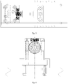
- the device is composed of a bottom plate 1, guide blocks 2,clamping slide blocks 3, mounting keys 4, hydraulic cylinders 5, hydraulic pipelines 6, connecting blocks 7, pressure claws 8, rotating shafts I 9, rotating shafts II 10,end face blocks 11, a mandrel 12, a mandrel seat 13, a locking jackscrew 14, a mandrel height adjusting post 15, a mandrel guide post 16, a mandrel guide post locking screw 17, a locking ring 18, circumferential positioning posts 19 and circumferential slide blocks 20.
- the bottom plate 1 is fixed on a machine tool via bolts
- the four guide blocks 2 are fixed on the bottom plate 1 by screws
- the clamping slide blocks 3 slide in slots of the guide blocks 2
- each end face block 11 can be placed in a clamping slide block 3 and fixed by two screws
- the end face blocks 11 and the clamping slide blocks 3 are fixed on the bottom plate 1 by screws
- the hydraulic cylinders 5 are fixed on the clamping slide blocks 3
- the end face blocks 11 scribed with scribed lines in the middle of end face positioning surfaces are fixed together with the clamping slide blocks 3; the clamping slide blocks 3 can slide in the slots of the guide blocks 2, the guide blocks 2 are scribed with scribed lines corresponding to different wheel sizes, and the positions of the scribed lines are determined according to the outer diameters of the rims of wheels having different sizes; when a wheel of one size is machined, the clamping slide blocks 3 fixed together with the end face blocks 11 can slide in the slots of the guide blocks 2, the scribed lines on the end face blocks 11 are aligned with the scribed lines of corresponding sizes on the guide blocks 2, then the end face blocks 11 and the clamping slide blocks 3 are fixed on the bottom plate 1 by bolts, and end face positioning of the wheel and adjustment of the compression position are thus realized.
- the mandrel 12 corresponding to the diameter of the central hole of the wheel is placed on the mandrel height adjusting post 15, the extending height of the mandrel height adjusting post 15 on the mandrel seat 13 is adjusted via the screw, the mandrel height adjusting post 15 is locked by the locking jackscrew 14 after the height is adjusted, and radial positioning adjustment of the wheel is thus completed.
- the circumferential slide blocks 20 slide to the pitch diameters of bolt holes or mounting holes of the wheel on the bottom plate 1, the circumferential positioning posts 19 are screwed down with the circumferential slide blocks 20, the circumferential positioning posts 19 can penetrate through the bolt holes or mounting holes of the wheel when the wheel is placed on the device, and a circumferential positioning function on the wheel is thus realized.
- the wheel is placed on the end face blocks 11, radial positioning of the central hole is realized via the mandrel 12, the circumferential positioning posts 19 penetrate through the bolt holes or mounting holes, then the extension rods of the hydraulic cylinders 5 move linearly via the hydraulic system to drive the connecting blocks 7 to move, the rotating shafts I 9 are thus driven to move in shaft slots of the pressure claws 8, the pressure claws 8 move circumferentially using the rotating shafts II 10 as circle centers, and the wheel is pressed.
- the above device is referred to as an experimental group 1.
- Experimental groups 1, 2 and 3 are simultaneously used for machining the same product and the time for replacing the fixture after machining is considered.
- the device in this embodiment has the advantages of shortening 7 days for manufacturing a fixture, reducing the cost for machining the fixture by more than 300 CNY, and reducing the time for replacing the fixture from original 2 hours to 20 minutes.
- the machining flow of the present invention is not obviously difference from the existing machining flow.
- this device can reduce the machining cost, shorten the manufacturing period of the fixture and improve the production efficiency.
Claims (5)
- Radfräs-Fensterhalterung, umfassend eine an einer Werkzeugmaschine befestigte Bodenplatte (1), Endflächenblöcke (11) zum Aufbringen des Rades darauf, einen Dorn (12) zum radialen Positionieren des zentralen Lochs des Rades und Druckkrallen (8) zum Pressen des Rades, dadurch gekennzeichnet
dass die Radfräs-Fensterhalterung Führungsblöcke (2), Klemmgleitblöcke (3), Montagekeilwelle (4), Hydraulikzylinder (5), Hydraulikleitungen (6), Verbindungsblöcke (7), rotierende Wellen I (9) und rotierende Wellen II (10) umfasst, die so angeordnet sind, dass die vier Führungsblöcke (2) an der Bodenplatte (1) befestigt sind, wobei die Klemmgleitblöcke (3) in Schlitzen der Führungsblöcke (2) gleiten, wobei jeder Endflächenblock (11) in einem Klemmgleitblock (3) befestigt ist, wobei die Endflächenblöcke (11) und die Klemmgleitblöcke (3) auf der Bodenplatte (1) befestigt sind, wobei die Hydraulikzylinder (5) auf den Klemmgleitblöcken (3) mit der Montagekeilwelle (4) befestigt sind, wobei die Hydraulikleitungen (6) an den Hydraulikzylindern (5) befestigt sind, wobei die Verbindungsblöcke (7) an den Verlängerungsenden der Hydraulikzylinder (5) befestigt sind, wobei die Druckklauen (8) über die rotierenden Wellen I (9) in Löcher der Verbindungsblöcke (7) angelenkt sind und gleichzeitig über die rotierenden Wellen II (10) mit den Endflächenblöcken (11) verbunden; und
dass die Radfräs-Fensterhalterung ferner einen Dornsitz (13), eine Verriegelungsdehnschraube (14), einen Dornhöhenverstellpfosten (15), einen Dornführungspfosten (16), eine Dornführungspfostenverriegelungsschraube (17), einen Verriegelungsring (18), Umfangspositionierungspfosten (19) und Umfangsgleitblöcke (20) umfasst, die so angeordnet sind, dass der Dornsitz (13) an der Bodenplatte (1) befestigt ist, wobei der Dornhöhenverstellpfosten (15) in Spielpassung in dem Loch des Dornsitzes (13) ist, wobei der Dornführungspfosten (16) in Spielpassung in dem Loch des Dornhöhenverstellpfostens (15) ist, wobei der Sicherungsring (18) und der Dornführungspfosten (15) durch die Dornführungspfostenverriegelungsschraube (17) verriegelt sind, wobei der Dorn (12) an dem Dornhöhenverstellpfosten (15) befestigt ist und die Umfangspositionierungspfosten (19) an den Umfangsgleitblöcken (20) befestigt sind. - Radfräs-Fensterhalterung nach Anspruch 1, dadurch gekennzeichnet, dass die Endflächenblöcke (11), die mit Ritzlinien in der Mitte der Endflächenpositionierungsflächen beschriftet sind, mit den Klemmgleitblöcken (3) zusammen befestigt sind; wobei die Klemmgleitblöcke (3) in den Schlitzen der Führungsblöcke (2) gleiten können, wobei die Führungsblöcke (2) mit Ritzlinien versehen sind, die unterschiedlichen Radgrößen entsprechen, und wobei die Positionen der Ritzlinien gemäß den äußeren Durchmesser der Felgen von Rädern unterschiedlicher Größe bestimmt werden; wobei wenn ein Rad einer Größe bearbeitet wird, können die zusammen mit den Endflächenblöcken (11) befestigten Klemmgleitblöcke (3) in den Schlitzen der Führungsblöcke (2) gleiten, wobei die Ritzlinien auf den Endflächenblöcken (11) mit den Ritzlinien entsprechender Größe auf den Führungsblöcken (2) ausgerichtet werden, dann werden die Endflächenblöcke (11) und die Klemmgleitblöcke (3) durch Bolzen an der Bodenplatte (1) befestigt, und die Endflächenpositionierung vom Rad und die Einstellung der Kompressionsposition sind somit realisiert.
- Radfräs-Fensterhalterung nach Anspruch 1, dadurch gekennzeichnet, dass der Dorn (12), der dem Durchmesser des zentralen Lochs des Rades entspricht, auf dem Dornhöhen-Einstellpfosten (15) angeordnet ist, wobei sich die Ausfahrhöhe des Dornhöheneinstellpfostens (15) auf dem Dornsitz (13) eingestellt wird, wobei der Dornhöhenverstellpfosten (15) durch die Verriegelungsdehnschraube (14) verriegelt wird, nachdem die Höhe eingestellt wird, und die radiale Positionierungseinstellung des Rades ist somit abgeschlossen.
- Radfräs-Fensterhalterung nach Anspruch 1, dadurch gekennzeichnet, dass die Umfangsgleitblöcke (20) auf die Teilungsdurchmesser von Bolzenlöchern oder Befestigungslöchern des Rades auf der Bodenplatte (1) gleiten, wobei der Umfangspositionierungspfosten (19) mit den Umfangsgleitblöcken (20) verschraubt sind, wobei die Umfangspositionierungspfosten (19) durch die Bolzenlöcher oder Befestigungslöcher des Rades eindringen können, wenn das Rad auf der Vorrichtung platziert wird, und somit ist eine umlaufende Positionierungsfunktion am Rad realisiert.
- Radfräs-Fensterhalterung nach Anspruch 1, dadurch gekennzeichnet, dass das Rad auf den Endflächenblöcken (11) angeordnet ist, wobei der Dorn (12) durch das zentrale Loch eindringt, wobei die Umfangspositionierungspfosten (19) durch die Schraubenlöcher oder Befestigungslöcher eindringen, dann bewegen sich die Verlängerungsstangen der Hydraulikzylinder (5) linear über das Hydrauliksystem, um die Verbindungsblöcke (7) zur Bewegung anzutreiben, so dass die rotierenden Wellen I (9) angetrieben werden, um sich in Wellenschlitzen der Druckklauen (8) zu bewegen, und wobei sich die Druckklauen (8) in Umfangsrichtung unter Verwendung der rotierenden Wellen II (10) als Kreismittelpunkte bewegen.
Applications Claiming Priority (1)
| Application Number | Priority Date | Filing Date | Title |
|---|---|---|---|
| CN201710746849.7A CN107378576A (zh) | 2017-08-27 | 2017-08-27 | 一种车轮铣窗口夹具 |
Publications (2)
| Publication Number | Publication Date |
|---|---|
| EP3450091A1 EP3450091A1 (de) | 2019-03-06 |
| EP3450091B1 true EP3450091B1 (de) | 2020-05-13 |
Family
ID=60346061
Family Applications (1)
| Application Number | Title | Priority Date | Filing Date |
|---|---|---|---|
| EP18190681.9A Active EP3450091B1 (de) | 2017-08-27 | 2018-08-24 | Radfräs-fensterhalterung |
Country Status (4)
| Country | Link |
|---|---|
| US (1) | US10427257B2 (de) |
| EP (1) | EP3450091B1 (de) |
| CN (1) | CN107378576A (de) |
| MA (1) | MA44570B1 (de) |
Families Citing this family (14)
| Publication number | Priority date | Publication date | Assignee | Title |
|---|---|---|---|---|
| CN108214024A (zh) * | 2018-01-23 | 2018-06-29 | 中信戴卡股份有限公司 | 一套锻造车轮铣加工夹具 |
| CN109877280A (zh) * | 2019-04-22 | 2019-06-14 | 河北光德精密机械股份有限公司 | 一种高温合金制件制备工艺中半自动面层淋砂装置 |
| CN112392273A (zh) * | 2019-08-13 | 2021-02-23 | 冈室昇志 | 两对接钢柱的倾斜及偏位对正装置 |
| CN110450976B (zh) * | 2019-08-28 | 2022-08-16 | 清远市巨劲科技有限公司 | 一种无人机校验治具 |
| CN110788638B (zh) * | 2019-11-01 | 2021-07-23 | 嘉善荣德金属制品股份有限公司 | 一种冷镦部件加工工装 |
| CN111922908A (zh) * | 2020-08-11 | 2020-11-13 | 灵璧县众泰五金有限公司 | 一种便于辅助全方位打磨的夹具及全方位调节方法 |
| CN112178066A (zh) * | 2020-11-22 | 2021-01-05 | 禹州市鼎源矿山机械设备有限公司 | 一种方便安装的矿山机械用盲轴座及其使用方法 |
| CN112496815A (zh) * | 2020-12-28 | 2021-03-16 | 河南恒远恒山工业有限公司 | 一种风力发电机底座锚盘钻孔定位夹紧装置 |
| CN113560642B (zh) * | 2021-09-27 | 2022-03-18 | 徐州泰和门窗有限公司 | 一种铝合金门窗加工用可调节厚度的切割装置 |
| CN114769628B (zh) * | 2022-03-09 | 2023-09-01 | 徐州康翔精密制造有限公司 | 一种传动轴车削装置 |
| CN114932390B (zh) * | 2022-04-27 | 2024-03-29 | 浙江华弈汽车零部件科技有限公司 | 一种汽车离合器弹簧的智能装配设备 |
| CN115091273A (zh) * | 2022-06-02 | 2022-09-23 | 宣城市君诚汽车零部件有限公司 | 一种汽车零部件生产用表面处理设备 |
| CN115026611B (zh) * | 2022-06-24 | 2023-08-08 | 云南昆船机械制造有限公司 | 一种用于快速车削的压紧夹具 |
| CN116857260B (zh) * | 2023-08-15 | 2024-02-13 | 北京金自天成液压技术有限责任公司 | 一种轧机hgc液压缸及其安装方法 |
Family Cites Families (14)
| Publication number | Priority date | Publication date | Assignee | Title |
|---|---|---|---|---|
| US5810341A (en) * | 1995-11-02 | 1998-09-22 | Tee-Lok Corporation | Truss table with integrated positioning stops |
| US7204493B1 (en) | 2004-06-03 | 2007-04-17 | Hayes Lemmerz International, Inc. | Lathe chuck with stepped jaws |
| US20070273108A1 (en) | 2006-05-26 | 2007-11-29 | Logansport Matsumoto Company, Inc. | Wheel Chuck |
| US7926797B2 (en) * | 2007-10-17 | 2011-04-19 | Adc Telecommunications, Inc. | Cable splint |
| DE102008014835A1 (de) | 2008-03-07 | 2009-09-10 | Chiron-Werke Gmbh & Co Kg | Werkzeugmaschine, insbesondere für Felgenbearbeitung |
| CN201544059U (zh) * | 2009-12-17 | 2010-08-11 | 中信戴卡轮毂制造股份有限公司 | 一种可调节高度的立车芯轴座 |
| CN201645183U (zh) * | 2010-03-25 | 2010-11-24 | 中信戴卡轮毂制造股份有限公司 | 一种可调的芯轴定位装置 |
| US8517361B2 (en) * | 2011-02-28 | 2013-08-27 | Eric Pello | Drawer front jig |
| DE202012011628U1 (de) | 2012-12-05 | 2013-01-08 | Siepe Gmbh & Co. Kg | Vorrichtung zum Entgraten von vorzugsweise runden Werkstücken aus Metall, insbesondere Leichtmetallfelgen |
| CN104760452B (zh) * | 2015-04-03 | 2017-04-26 | 中信戴卡股份有限公司 | 一种车轮刻字翻转夹具 |
| CN104924169A (zh) * | 2015-06-03 | 2015-09-23 | 中信戴卡股份有限公司 | 一种车轮去毛刺装置 |
| CN105522425A (zh) * | 2016-01-21 | 2016-04-27 | 中信戴卡股份有限公司 | 一种铝合金轮毂车床夹盘 |
| CN105537634A (zh) * | 2016-01-22 | 2016-05-04 | 中信戴卡股份有限公司 | 一种铝合金轮毂车床夹盘 |
| CN106737308B (zh) * | 2017-02-24 | 2018-10-09 | 中信戴卡股份有限公司 | 柔性装夹装置 |
-
2017
- 2017-08-27 CN CN201710746849.7A patent/CN107378576A/zh active Pending
- 2017-11-09 US US15/808,260 patent/US10427257B2/en active Active
-
2018
- 2018-08-24 EP EP18190681.9A patent/EP3450091B1/de active Active
- 2018-08-24 MA MA44570A patent/MA44570B1/fr unknown
Non-Patent Citations (1)
| Title |
|---|
| None * |
Also Published As
| Publication number | Publication date |
|---|---|
| US10427257B2 (en) | 2019-10-01 |
| MA44570B1 (fr) | 2020-07-29 |
| US20190061078A1 (en) | 2019-02-28 |
| CN107378576A (zh) | 2017-11-24 |
| EP3450091A1 (de) | 2019-03-06 |
Similar Documents
| Publication | Publication Date | Title |
|---|---|---|
| EP3450091B1 (de) | Radfräs-fensterhalterung | |
| CN110253352B (zh) | 一种用于轴承内外圈夹紧磨削的一体化夹具 | |
| CN109079204B (zh) | 一种发动机喷嘴环斜孔钻模 | |
| CN102921983A (zh) | 内涨式夹紧装置 | |
| CN102211213B (zh) | 车加工大型套筒类零件内胀式定心夹具 | |
| CN203184775U (zh) | 一种滚齿夹具 | |
| CN202088012U (zh) | 一种孔用机械夹紧弹簧夹头 | |
| CN211387238U (zh) | 一种大型内齿圈工件自动找正及锁紧结构 | |
| CN214519014U (zh) | 车床试件定位夹具 | |
| CN104589112A (zh) | 一种用于凸轮轴端面加工的夹具 | |
| CN113927334A (zh) | 一种薄壁毂类零件加工装置 | |
| CN209831004U (zh) | 一种适用于多品种轴套组合式气动加工夹具 | |
| CN210475756U (zh) | 采用同轴定位辅助夹紧方式的齿轮夹具 | |
| CN104646709A (zh) | 偏心盘的加工方法 | |
| CN101954516A (zh) | 齿轮铣床胎夹具 | |
| CN220112809U (zh) | 一种台阶阀加工用夹具 | |
| CN220699481U (zh) | 钻井泵缸套丝扣圈拆装工具 | |
| CN204075271U (zh) | 车床气动涨芯夹紧装置 | |
| CN209811751U (zh) | 一种轴套加工夹具 | |
| CN220161890U (zh) | 一种专用锥度胀紧芯轴 | |
| CN220030793U (zh) | 一种手动胀紧式夹具 | |
| CN218926301U (zh) | 一种油缸筒双胀夹持装置 | |
| CN219484227U (zh) | 一种液力变矩器盖总成摩擦面粗车防转夹具 | |
| CN218947009U (zh) | 一种转向节臂机床夹具 | |
| CN217619287U (zh) | 曲轴曲拐轴颈外圆车加工夹具 |
Legal Events
| Date | Code | Title | Description |
|---|---|---|---|
| PUAI | Public reference made under article 153(3) epc to a published international application that has entered the european phase |
Free format text: ORIGINAL CODE: 0009012 |
|
| STAA | Information on the status of an ep patent application or granted ep patent |
Free format text: STATUS: REQUEST FOR EXAMINATION WAS MADE |
|
| 17P | Request for examination filed |
Effective date: 20180824 |
|
| AK | Designated contracting states |
Kind code of ref document: A1 Designated state(s): AL AT BE BG CH CY CZ DE DK EE ES FI FR GB GR HR HU IE IS IT LI LT LU LV MC MK MT NL NO PL PT RO RS SE SI SK SM TR |
|
| AX | Request for extension of the european patent |
Extension state: BA ME |
|
| GRAP | Despatch of communication of intention to grant a patent |
Free format text: ORIGINAL CODE: EPIDOSNIGR1 |
|
| STAA | Information on the status of an ep patent application or granted ep patent |
Free format text: STATUS: GRANT OF PATENT IS INTENDED |
|
| INTG | Intention to grant announced |
Effective date: 20191217 |
|
| GRAS | Grant fee paid |
Free format text: ORIGINAL CODE: EPIDOSNIGR3 |
|
| GRAA | (expected) grant |
Free format text: ORIGINAL CODE: 0009210 |
|
| STAA | Information on the status of an ep patent application or granted ep patent |
Free format text: STATUS: THE PATENT HAS BEEN GRANTED |
|
| AK | Designated contracting states |
Kind code of ref document: B1 Designated state(s): AL AT BE BG CH CY CZ DE DK EE ES FI FR GB GR HR HU IE IS IT LI LT LU LV MC MK MT NL NO PL PT RO RS SE SI SK SM TR |
|
| REG | Reference to a national code |
Ref country code: GB Ref legal event code: FG4D |
|
| REG | Reference to a national code |
Ref country code: CH Ref legal event code: EP |
|
| REG | Reference to a national code |
Ref country code: DE Ref legal event code: R096 Ref document number: 602018004497 Country of ref document: DE |
|
| REG | Reference to a national code |
Ref country code: AT Ref legal event code: REF Ref document number: 1269629 Country of ref document: AT Kind code of ref document: T Effective date: 20200615 |
|
| REG | Reference to a national code |
Ref country code: MA Ref legal event code: VAGR Ref document number: 44570 Country of ref document: MA Kind code of ref document: B1 |
|
| REG | Reference to a national code |
Ref country code: LT Ref legal event code: MG4D |
|
| REG | Reference to a national code |
Ref country code: NL Ref legal event code: MP Effective date: 20200513 |
|
| PG25 | Lapsed in a contracting state [announced via postgrant information from national office to epo] |
Ref country code: FI Free format text: LAPSE BECAUSE OF FAILURE TO SUBMIT A TRANSLATION OF THE DESCRIPTION OR TO PAY THE FEE WITHIN THE PRESCRIBED TIME-LIMIT Effective date: 20200513 Ref country code: LT Free format text: LAPSE BECAUSE OF FAILURE TO SUBMIT A TRANSLATION OF THE DESCRIPTION OR TO PAY THE FEE WITHIN THE PRESCRIBED TIME-LIMIT Effective date: 20200513 Ref country code: PT Free format text: LAPSE BECAUSE OF FAILURE TO SUBMIT A TRANSLATION OF THE DESCRIPTION OR TO PAY THE FEE WITHIN THE PRESCRIBED TIME-LIMIT Effective date: 20200914 Ref country code: IS Free format text: LAPSE BECAUSE OF FAILURE TO SUBMIT A TRANSLATION OF THE DESCRIPTION OR TO PAY THE FEE WITHIN THE PRESCRIBED TIME-LIMIT Effective date: 20200913 Ref country code: SE Free format text: LAPSE BECAUSE OF FAILURE TO SUBMIT A TRANSLATION OF THE DESCRIPTION OR TO PAY THE FEE WITHIN THE PRESCRIBED TIME-LIMIT Effective date: 20200513 Ref country code: GR Free format text: LAPSE BECAUSE OF FAILURE TO SUBMIT A TRANSLATION OF THE DESCRIPTION OR TO PAY THE FEE WITHIN THE PRESCRIBED TIME-LIMIT Effective date: 20200814 Ref country code: NO Free format text: LAPSE BECAUSE OF FAILURE TO SUBMIT A TRANSLATION OF THE DESCRIPTION OR TO PAY THE FEE WITHIN THE PRESCRIBED TIME-LIMIT Effective date: 20200813 |
|
| PG25 | Lapsed in a contracting state [announced via postgrant information from national office to epo] |
Ref country code: RS Free format text: LAPSE BECAUSE OF FAILURE TO SUBMIT A TRANSLATION OF THE DESCRIPTION OR TO PAY THE FEE WITHIN THE PRESCRIBED TIME-LIMIT Effective date: 20200513 Ref country code: HR Free format text: LAPSE BECAUSE OF FAILURE TO SUBMIT A TRANSLATION OF THE DESCRIPTION OR TO PAY THE FEE WITHIN THE PRESCRIBED TIME-LIMIT Effective date: 20200513 Ref country code: BG Free format text: LAPSE BECAUSE OF FAILURE TO SUBMIT A TRANSLATION OF THE DESCRIPTION OR TO PAY THE FEE WITHIN THE PRESCRIBED TIME-LIMIT Effective date: 20200813 Ref country code: LV Free format text: LAPSE BECAUSE OF FAILURE TO SUBMIT A TRANSLATION OF THE DESCRIPTION OR TO PAY THE FEE WITHIN THE PRESCRIBED TIME-LIMIT Effective date: 20200513 |
|
| REG | Reference to a national code |
Ref country code: AT Ref legal event code: MK05 Ref document number: 1269629 Country of ref document: AT Kind code of ref document: T Effective date: 20200513 |
|
| PG25 | Lapsed in a contracting state [announced via postgrant information from national office to epo] |
Ref country code: AL Free format text: LAPSE BECAUSE OF FAILURE TO SUBMIT A TRANSLATION OF THE DESCRIPTION OR TO PAY THE FEE WITHIN THE PRESCRIBED TIME-LIMIT Effective date: 20200513 Ref country code: NL Free format text: LAPSE BECAUSE OF FAILURE TO SUBMIT A TRANSLATION OF THE DESCRIPTION OR TO PAY THE FEE WITHIN THE PRESCRIBED TIME-LIMIT Effective date: 20200513 |
|
| PG25 | Lapsed in a contracting state [announced via postgrant information from national office to epo] |
Ref country code: ES Free format text: LAPSE BECAUSE OF FAILURE TO SUBMIT A TRANSLATION OF THE DESCRIPTION OR TO PAY THE FEE WITHIN THE PRESCRIBED TIME-LIMIT Effective date: 20200513 Ref country code: RO Free format text: LAPSE BECAUSE OF FAILURE TO SUBMIT A TRANSLATION OF THE DESCRIPTION OR TO PAY THE FEE WITHIN THE PRESCRIBED TIME-LIMIT Effective date: 20200513 Ref country code: IT Free format text: LAPSE BECAUSE OF FAILURE TO SUBMIT A TRANSLATION OF THE DESCRIPTION OR TO PAY THE FEE WITHIN THE PRESCRIBED TIME-LIMIT Effective date: 20200513 Ref country code: AT Free format text: LAPSE BECAUSE OF FAILURE TO SUBMIT A TRANSLATION OF THE DESCRIPTION OR TO PAY THE FEE WITHIN THE PRESCRIBED TIME-LIMIT Effective date: 20200513 Ref country code: CZ Free format text: LAPSE BECAUSE OF FAILURE TO SUBMIT A TRANSLATION OF THE DESCRIPTION OR TO PAY THE FEE WITHIN THE PRESCRIBED TIME-LIMIT Effective date: 20200513 Ref country code: SM Free format text: LAPSE BECAUSE OF FAILURE TO SUBMIT A TRANSLATION OF THE DESCRIPTION OR TO PAY THE FEE WITHIN THE PRESCRIBED TIME-LIMIT Effective date: 20200513 Ref country code: EE Free format text: LAPSE BECAUSE OF FAILURE TO SUBMIT A TRANSLATION OF THE DESCRIPTION OR TO PAY THE FEE WITHIN THE PRESCRIBED TIME-LIMIT Effective date: 20200513 Ref country code: DK Free format text: LAPSE BECAUSE OF FAILURE TO SUBMIT A TRANSLATION OF THE DESCRIPTION OR TO PAY THE FEE WITHIN THE PRESCRIBED TIME-LIMIT Effective date: 20200513 |
|
| REG | Reference to a national code |
Ref country code: DE Ref legal event code: R097 Ref document number: 602018004497 Country of ref document: DE |
|
| PG25 | Lapsed in a contracting state [announced via postgrant information from national office to epo] |
Ref country code: SK Free format text: LAPSE BECAUSE OF FAILURE TO SUBMIT A TRANSLATION OF THE DESCRIPTION OR TO PAY THE FEE WITHIN THE PRESCRIBED TIME-LIMIT Effective date: 20200513 Ref country code: PL Free format text: LAPSE BECAUSE OF FAILURE TO SUBMIT A TRANSLATION OF THE DESCRIPTION OR TO PAY THE FEE WITHIN THE PRESCRIBED TIME-LIMIT Effective date: 20200513 |
|
| PLBE | No opposition filed within time limit |
Free format text: ORIGINAL CODE: 0009261 |
|
| STAA | Information on the status of an ep patent application or granted ep patent |
Free format text: STATUS: NO OPPOSITION FILED WITHIN TIME LIMIT |
|
| PG25 | Lapsed in a contracting state [announced via postgrant information from national office to epo] |
Ref country code: MC Free format text: LAPSE BECAUSE OF FAILURE TO SUBMIT A TRANSLATION OF THE DESCRIPTION OR TO PAY THE FEE WITHIN THE PRESCRIBED TIME-LIMIT Effective date: 20200513 |
|
| 26N | No opposition filed |
Effective date: 20210216 |
|
| PG25 | Lapsed in a contracting state [announced via postgrant information from national office to epo] |
Ref country code: LU Free format text: LAPSE BECAUSE OF NON-PAYMENT OF DUE FEES Effective date: 20200824 |
|
| REG | Reference to a national code |
Ref country code: BE Ref legal event code: MM Effective date: 20200831 |
|
| PG25 | Lapsed in a contracting state [announced via postgrant information from national office to epo] |
Ref country code: SI Free format text: LAPSE BECAUSE OF FAILURE TO SUBMIT A TRANSLATION OF THE DESCRIPTION OR TO PAY THE FEE WITHIN THE PRESCRIBED TIME-LIMIT Effective date: 20200513 |
|
| VSFP | Annual fee paid to validation state [announced via postgrant information from national office to epo] |
Ref country code: MA Payment date: 20201001 Year of fee payment: 3 |
|
| PG25 | Lapsed in a contracting state [announced via postgrant information from national office to epo] |
Ref country code: IE Free format text: LAPSE BECAUSE OF NON-PAYMENT OF DUE FEES Effective date: 20200824 Ref country code: BE Free format text: LAPSE BECAUSE OF NON-PAYMENT OF DUE FEES Effective date: 20200831 |
|
| REG | Reference to a national code |
Ref country code: CH Ref legal event code: PL |
|
| PG25 | Lapsed in a contracting state [announced via postgrant information from national office to epo] |
Ref country code: LI Free format text: LAPSE BECAUSE OF NON-PAYMENT OF DUE FEES Effective date: 20210831 Ref country code: CH Free format text: LAPSE BECAUSE OF NON-PAYMENT OF DUE FEES Effective date: 20210831 |
|
| PG25 | Lapsed in a contracting state [announced via postgrant information from national office to epo] |
Ref country code: TR Free format text: LAPSE BECAUSE OF FAILURE TO SUBMIT A TRANSLATION OF THE DESCRIPTION OR TO PAY THE FEE WITHIN THE PRESCRIBED TIME-LIMIT Effective date: 20200513 Ref country code: MT Free format text: LAPSE BECAUSE OF FAILURE TO SUBMIT A TRANSLATION OF THE DESCRIPTION OR TO PAY THE FEE WITHIN THE PRESCRIBED TIME-LIMIT Effective date: 20200513 Ref country code: CY Free format text: LAPSE BECAUSE OF FAILURE TO SUBMIT A TRANSLATION OF THE DESCRIPTION OR TO PAY THE FEE WITHIN THE PRESCRIBED TIME-LIMIT Effective date: 20200513 |
|
| PG25 | Lapsed in a contracting state [announced via postgrant information from national office to epo] |
Ref country code: MK Free format text: LAPSE BECAUSE OF FAILURE TO SUBMIT A TRANSLATION OF THE DESCRIPTION OR TO PAY THE FEE WITHIN THE PRESCRIBED TIME-LIMIT Effective date: 20200513 |
|
| GBPC | Gb: european patent ceased through non-payment of renewal fee |
Effective date: 20220824 |
|
| PG25 | Lapsed in a contracting state [announced via postgrant information from national office to epo] |
Ref country code: GB Free format text: LAPSE BECAUSE OF NON-PAYMENT OF DUE FEES Effective date: 20220824 |
|
| PGFP | Annual fee paid to national office [announced via postgrant information from national office to epo] |
Ref country code: FR Payment date: 20230828 Year of fee payment: 6 Ref country code: DE Payment date: 20230808 Year of fee payment: 6 |