EP3450091B1 - Wheel milling window fixture - Google Patents
Wheel milling window fixture Download PDFInfo
- Publication number
- EP3450091B1 EP3450091B1 EP18190681.9A EP18190681A EP3450091B1 EP 3450091 B1 EP3450091 B1 EP 3450091B1 EP 18190681 A EP18190681 A EP 18190681A EP 3450091 B1 EP3450091 B1 EP 3450091B1
- Authority
- EP
- European Patent Office
- Prior art keywords
- blocks
- mandrel
- wheel
- fixed
- face
- Prior art date
- Legal status (The legal status is an assumption and is not a legal conclusion. Google has not performed a legal analysis and makes no representation as to the accuracy of the status listed.)
- Active
Links
- 238000003801 milling Methods 0.000 title claims description 24
- 210000000078 claw Anatomy 0.000 claims description 15
- 230000006835 compression Effects 0.000 claims description 3
- 238000007906 compression Methods 0.000 claims description 3
- 238000003825 pressing Methods 0.000 claims description 2
- 238000003754 machining Methods 0.000 description 10
- 238000004519 manufacturing process Methods 0.000 description 10
- 238000010586 diagram Methods 0.000 description 2
- 238000000034 method Methods 0.000 description 2
- 230000000694 effects Effects 0.000 description 1
- 238000004904 shortening Methods 0.000 description 1
Images


Classifications
-
- B—PERFORMING OPERATIONS; TRANSPORTING
- B23—MACHINE TOOLS; METAL-WORKING NOT OTHERWISE PROVIDED FOR
- B23Q—DETAILS, COMPONENTS, OR ACCESSORIES FOR MACHINE TOOLS, e.g. ARRANGEMENTS FOR COPYING OR CONTROLLING; MACHINE TOOLS IN GENERAL CHARACTERISED BY THE CONSTRUCTION OF PARTICULAR DETAILS OR COMPONENTS; COMBINATIONS OR ASSOCIATIONS OF METAL-WORKING MACHINES, NOT DIRECTED TO A PARTICULAR RESULT
- B23Q3/00—Devices holding, supporting, or positioning work or tools, of a kind normally removable from the machine
- B23Q3/02—Devices holding, supporting, or positioning work or tools, of a kind normally removable from the machine for mounting on a work-table, tool-slide, or analogous part
- B23Q3/06—Work-clamping means
- B23Q3/062—Work-clamping means adapted for holding workpieces having a special form or being made from a special material
-
- B—PERFORMING OPERATIONS; TRANSPORTING
- B23—MACHINE TOOLS; METAL-WORKING NOT OTHERWISE PROVIDED FOR
- B23C—MILLING
- B23C3/00—Milling particular work; Special milling operations; Machines therefor
-
- B—PERFORMING OPERATIONS; TRANSPORTING
- B23—MACHINE TOOLS; METAL-WORKING NOT OTHERWISE PROVIDED FOR
- B23Q—DETAILS, COMPONENTS, OR ACCESSORIES FOR MACHINE TOOLS, e.g. ARRANGEMENTS FOR COPYING OR CONTROLLING; MACHINE TOOLS IN GENERAL CHARACTERISED BY THE CONSTRUCTION OF PARTICULAR DETAILS OR COMPONENTS; COMBINATIONS OR ASSOCIATIONS OF METAL-WORKING MACHINES, NOT DIRECTED TO A PARTICULAR RESULT
- B23Q3/00—Devices holding, supporting, or positioning work or tools, of a kind normally removable from the machine
- B23Q3/02—Devices holding, supporting, or positioning work or tools, of a kind normally removable from the machine for mounting on a work-table, tool-slide, or analogous part
- B23Q3/06—Work-clamping means
- B23Q3/08—Work-clamping means other than mechanically-actuated
- B23Q3/082—Work-clamping means other than mechanically-actuated hydraulically actuated
-
- B—PERFORMING OPERATIONS; TRANSPORTING
- B23—MACHINE TOOLS; METAL-WORKING NOT OTHERWISE PROVIDED FOR
- B23C—MILLING
- B23C2215/00—Details of workpieces
- B23C2215/08—Automotive parts
- B23C2215/085—Wheels
-
- B—PERFORMING OPERATIONS; TRANSPORTING
- B23—MACHINE TOOLS; METAL-WORKING NOT OTHERWISE PROVIDED FOR
- B23C—MILLING
- B23C2270/00—Details of milling machines, milling processes or milling tools not otherwise provided for
- B23C2270/02—Use of a particular power source
- B23C2270/025—Hydraulics
-
- B—PERFORMING OPERATIONS; TRANSPORTING
- B23—MACHINE TOOLS; METAL-WORKING NOT OTHERWISE PROVIDED FOR
- B23C—MILLING
- B23C2270/00—Details of milling machines, milling processes or milling tools not otherwise provided for
- B23C2270/08—Clamping mechanisms or provision for clamping
-
- B—PERFORMING OPERATIONS; TRANSPORTING
- B23—MACHINE TOOLS; METAL-WORKING NOT OTHERWISE PROVIDED FOR
- B23Q—DETAILS, COMPONENTS, OR ACCESSORIES FOR MACHINE TOOLS, e.g. ARRANGEMENTS FOR COPYING OR CONTROLLING; MACHINE TOOLS IN GENERAL CHARACTERISED BY THE CONSTRUCTION OF PARTICULAR DETAILS OR COMPONENTS; COMBINATIONS OR ASSOCIATIONS OF METAL-WORKING MACHINES, NOT DIRECTED TO A PARTICULAR RESULT
- B23Q2703/00—Work clamping
- B23Q2703/02—Work clamping means
- B23Q2703/04—Work clamping means using fluid means or a vacuum
-
- B—PERFORMING OPERATIONS; TRANSPORTING
- B23—MACHINE TOOLS; METAL-WORKING NOT OTHERWISE PROVIDED FOR
- B23Q—DETAILS, COMPONENTS, OR ACCESSORIES FOR MACHINE TOOLS, e.g. ARRANGEMENTS FOR COPYING OR CONTROLLING; MACHINE TOOLS IN GENERAL CHARACTERISED BY THE CONSTRUCTION OF PARTICULAR DETAILS OR COMPONENTS; COMBINATIONS OR ASSOCIATIONS OF METAL-WORKING MACHINES, NOT DIRECTED TO A PARTICULAR RESULT
- B23Q2703/00—Work clamping
- B23Q2703/02—Work clamping means
- B23Q2703/10—Devices for clamping workpieces of a particular form or made from a particular material
Definitions
- the present invention relates to a milling fixture, specifically to a wheel milling window fixture.
- Wheel windows need to be machined in the machining process of automobile wheels, and particularly, wheel windows of forged wheel products are substantially machined in a manner of milling.
- Milling fixtures for windows generally realize central positioning via fixed expansion sleeves or mandrels.
- expansion sleeves or mandrels having corresponding heights need to be manufactured according to different products; and axial positioning often only adapts to fixtures of one size according to the magnitude of radial sizes of wheels, thereby bringing much inconvenience on the aspect of replacing the fixtures and influencing the production efficiency.
- DE 10 2008 014 835 A1 discloses a machine tool for machining workpieces, comprising a workpiece support for mounting the workpiece, a tool holder for holding a tool for machining the workpiece, and workpiece holding units for fixing and centering the workpiece during the machining.
- the holding elements can each be moved substantially parallel to the workpiece support surface in the direction toward the workpiece, in particular in the direction toward a central workpiece axis, which runs perpendicular to the workpiece support surface, to center and fix the workpiece.
- the present invention is aimed at providing a wheel milling window device. According to the heights and diameters of different products, the fixture can be quickly adjusted via self-structure, thereby reducing manufacturing of fixtures, reducing the production cost and improving the production efficiency of wheels.
- a wheel milling window device is composed of a bottom plate, guide blocks, clamping slide blocks, mounting keys, hydraulic cylinders, hydraulic pipelines, connecting blocks, pressure claws, rotating shafts I, rotating shafts II, end face blocks, a mandrel, a mandrel seat, a locking jackscrew, a mandrel height adjusting post, a mandrel guide post, a mandrel guide post locking screw, a locking ring, circumferential positioning posts and circumferential slide blocks .
- the bottom plate is fixed on a machine tool via bolts
- the four guide blocks are fixed on the bottom plate by screws
- the clamping slide blocks slide in slots of the guide blocks
- each end face block can be placed in a clamping slide block and fixed by two screws
- the end face blocks and the clamping slide blocks are fixed on the bottom plate by screws
- the hydraulic cylinders are fixed on the clamping slide blocks by the mounting keys and screws, meanwhile, the hydraulic pipeline
- the present invention provides a wheel milling window fixture, comprising a bottom plate fixed on a machine tool, end face blocks for placing the wheel thereon, a mandrel for radial positioning of the central hole of the wheel and pressure claws for pressing the wheel, wherein
- the wheel milling window fixture comprises guide blocks, clamping slide blocks, mounting keys, hydraulic cylinders, hydraulic pipelines, connecting blocks, rotating shafts I and rotating shafts II, arranged in such a way that the four guide blocks are fixed on the bottom plate, the clamping slide blocks slide in slots of the guide blocks, each end face block is fixed in a clamping slide block, the end face blocks and the clamping slide blocks are fixed on the bottom plate, the hydraulic cylinders are fixed on the clamping slide blocks by the mounting keys, the hydraulic pipelines are fixed on the hydraulic cylinders, the connecting blocks are fixed at the extension ends of the hydraulic cylinders, the pressure claws are articulated into holes of the connecting blocks via the rotating shafts I and simultaneously articulated to the end face blocks via the rotating shafts II; and wherein the wheel milling window fixture further comprises a mandrel seat, a locking jackscrew, a mandrel height adjusting post, a mandrel guide post, a mandrel guide post locking screw, a locking ring, circumferential positioning
- the end face blocks scribed with scribed lines in the middle of end face positioning surfaces are fixed together with the clamping slide blocks ;
- the clamping slide blocks can slide in the slots of the guide blocks, the guide blocks are scribed with scribed lines corresponding to different wheel sizes, and the positions of the scribed lines are determined according to the outer diameters of the rims of wheels having different sizes;
- the clamping slide blocks fixed together with the end face blocks can slide in the slots of the guide blocks, the scribed lines on the end face blocks are aligned with the scribed lines of corresponding sizes on the guide blocks, then the end face blocks and the clamping slide blocks are fixed on the bottom plate by bolts, and end face positioning of the wheel and adjustment of the compression position are thus realized.
- the mandrel corresponding to the diameter of the central hole of the wheel is placed on the mandrel height adjusting post, the extending height of the mandrel height adjusting post on the mandrel seat is adjusted via the screw, the mandrel height adjusting post is locked by the locking jackscrew after the height is adjusted, and radial positioning adjustment of the wheel is thus completed.
- the circumferential slide blocks slide to the pitch diameters of bolt holes or mounting holes of the wheel on the bottom plate, the circumferential positioning posts are screwed down with the circumferential slide blocks, the circumferential positioning posts can penetrate through the bolt holes or mounting holes of the wheel when the wheel is placed on the device, and a circumferential positioning function on the wheel is thus realized.
- the wheel is placed on the end face blocks, radial positioning of the central hole is realized via the mandrel, the circumferential positioning posts penetrate through the bolt holes or mounting holes, then the extension rods of the hydraulic cylinders move linearly via the hydraulic system to drive the connecting blocks to move, the rotating shafts I are thus driven to move in shaft slots of the pressure claws, the pressure claws move circumferentially using the rotating shafts II as circle centers, and the wheel is pressed.
- the guide blocks are fixed on the bottom plate and scribed with corresponding scribed lines according to wheels having different diameters, the end face blocks and the clamping slide blocks are fixed together, and the end face blocks are scribed with scribed lines; when a wheel type is changed, the fixture may not be completely detached, but fixing screws on the end face blocks are unscrewed, then the end face blocks and the clamping slide blocks slide to the positions of corresponding sizes in the guide blocks, finally, the end face blocks and the clamping slide blocks are screwed down on the bottom plate via the screws, and the effect of quickly replacing the fixture is achieved.
- the height of the mandrel can be axially adjusted to adapt to the products having different heights, so that mandrels having corresponding heights, manufactured according to different heights like before, can be reduced, the production cost is reduced, the manufacturing period of the fixture is shortened, and the production efficiency is improved.
- Embodiment 1 discloses a wheel milling window device.
- the device is composed of a bottom plate 1, guide blocks 2,clamping slide blocks 3, mounting keys 4, hydraulic cylinders 5, hydraulic pipelines 6, connecting blocks 7, pressure claws 8, rotating shafts I 9, rotating shafts II 10,end face blocks 11, a mandrel 12, a mandrel seat 13, a locking jackscrew 14, a mandrel height adjusting post 15, a mandrel guide post 16, a mandrel guide post locking screw 17, a locking ring 18, circumferential positioning posts 19 and circumferential slide blocks 20.
- the bottom plate 1 is fixed on a machine tool via bolts
- the four guide blocks 2 are fixed on the bottom plate 1 by screws
- the clamping slide blocks 3 slide in slots of the guide blocks 2
- each end face block 11 can be placed in a clamping slide block 3 and fixed by two screws
- the end face blocks 11 and the clamping slide blocks 3 are fixed on the bottom plate 1 by screws
- the hydraulic cylinders 5 are fixed on the clamping slide blocks 3
- the end face blocks 11 scribed with scribed lines in the middle of end face positioning surfaces are fixed together with the clamping slide blocks 3; the clamping slide blocks 3 can slide in the slots of the guide blocks 2, the guide blocks 2 are scribed with scribed lines corresponding to different wheel sizes, and the positions of the scribed lines are determined according to the outer diameters of the rims of wheels having different sizes; when a wheel of one size is machined, the clamping slide blocks 3 fixed together with the end face blocks 11 can slide in the slots of the guide blocks 2, the scribed lines on the end face blocks 11 are aligned with the scribed lines of corresponding sizes on the guide blocks 2, then the end face blocks 11 and the clamping slide blocks 3 are fixed on the bottom plate 1 by bolts, and end face positioning of the wheel and adjustment of the compression position are thus realized.
- the mandrel 12 corresponding to the diameter of the central hole of the wheel is placed on the mandrel height adjusting post 15, the extending height of the mandrel height adjusting post 15 on the mandrel seat 13 is adjusted via the screw, the mandrel height adjusting post 15 is locked by the locking jackscrew 14 after the height is adjusted, and radial positioning adjustment of the wheel is thus completed.
- the circumferential slide blocks 20 slide to the pitch diameters of bolt holes or mounting holes of the wheel on the bottom plate 1, the circumferential positioning posts 19 are screwed down with the circumferential slide blocks 20, the circumferential positioning posts 19 can penetrate through the bolt holes or mounting holes of the wheel when the wheel is placed on the device, and a circumferential positioning function on the wheel is thus realized.
- the wheel is placed on the end face blocks 11, radial positioning of the central hole is realized via the mandrel 12, the circumferential positioning posts 19 penetrate through the bolt holes or mounting holes, then the extension rods of the hydraulic cylinders 5 move linearly via the hydraulic system to drive the connecting blocks 7 to move, the rotating shafts I 9 are thus driven to move in shaft slots of the pressure claws 8, the pressure claws 8 move circumferentially using the rotating shafts II 10 as circle centers, and the wheel is pressed.
- the above device is referred to as an experimental group 1.
- Experimental groups 1, 2 and 3 are simultaneously used for machining the same product and the time for replacing the fixture after machining is considered.
- the device in this embodiment has the advantages of shortening 7 days for manufacturing a fixture, reducing the cost for machining the fixture by more than 300 CNY, and reducing the time for replacing the fixture from original 2 hours to 20 minutes.
- the machining flow of the present invention is not obviously difference from the existing machining flow.
- this device can reduce the machining cost, shorten the manufacturing period of the fixture and improve the production efficiency.
Landscapes
- Engineering & Computer Science (AREA)
- Mechanical Engineering (AREA)
- Processing Of Stones Or Stones Resemblance Materials (AREA)
- Re-Forming, After-Treatment, Cutting And Transporting Of Glass Products (AREA)
- Milling Processes (AREA)
Description
- The present invention relates to a milling fixture, specifically to a wheel milling window fixture.
- Wheel windows need to be machined in the machining process of automobile wheels, and particularly, wheel windows of forged wheel products are substantially machined in a manner of milling.
- Milling fixtures for windows generally realize central positioning via fixed expansion sleeves or mandrels. However, due to the diversity of heights of wheel products, expansion sleeves or mandrels having corresponding heights need to be manufactured according to different products; and axial positioning often only adapts to fixtures of one size according to the magnitude of radial sizes of wheels, thereby bringing much inconvenience on the aspect of replacing the fixtures and influencing the production efficiency.
-
DE 10 2008 014 835 A1 - The present invention is aimed at providing a wheel milling window device. According to the heights and diameters of different products, the fixture can be quickly adjusted via self-structure, thereby reducing manufacturing of fixtures, reducing the production cost and improving the production efficiency of wheels.
- In order to fulfill the above aim, the present invention adopts the technical solution: a wheel milling window device. The device is composed of a bottom plate, guide blocks, clamping slide blocks, mounting keys, hydraulic cylinders, hydraulic pipelines, connecting blocks, pressure claws, rotating shafts I, rotating shafts II, end face blocks, a mandrel, a mandrel seat, a locking jackscrew, a mandrel height adjusting post, a mandrel guide post, a mandrel guide post locking screw, a locking ring, circumferential positioning posts and circumferential slide blocks .The bottom plate is fixed on a machine tool via bolts, the four guide blocks are fixed on the bottom plate by screws, the clamping slide blocks slide in slots of the guide blocks, each end face block can be placed in a clamping slide block and fixed by two screws, the end face blocks and the clamping slide blocks are fixed on the bottom plate by screws, the hydraulic cylinders are fixed on the clamping slide blocks by the mounting keys and screws, meanwhile, the hydraulic pipelines are connected and fixed to the hydraulic cylinders via screws, the connecting blocks are fixed at the extension ends of the hydraulic cylinders via threaded connection, the pressure claws are articulated into holes of the connecting blocks via the rotating shafts I and simultaneously articulated to the end face blocks via the rotating shafts II, the mandrel seat is fixed on the bottom plate via six screws, the mandrel height adjusting post is in clearance fit in the hole of the mandrel seat, the mandrel guide post is in clearance fit in the hole of the mandrel height adjusting post, the locking ring and the mandrel guide post are locked via threads by the mandrel guide post locking screw, the mandrel is fixed on the mandrel height adjusting post by a screw, and the circumferential positioning posts can be fixed on the circumferential slide blocks via threads.
- More specifically, the present invention provides a wheel milling window fixture, comprising a bottom plate fixed on a machine tool, end face blocks for placing the wheel thereon, a mandrel for radial positioning of the central hole of the wheel and pressure claws for pressing the wheel, wherein
- the wheel milling window fixture comprises guide blocks, clamping slide blocks, mounting keys, hydraulic cylinders, hydraulic pipelines, connecting blocks, rotating shafts I and rotating shafts II, arranged in such a way that the four guide blocks are fixed on the bottom plate, the clamping slide blocks slide in slots of the guide blocks, each end face block is fixed in a clamping slide block, the end face blocks and the clamping slide blocks are fixed on the bottom plate, the hydraulic cylinders are fixed on the clamping slide blocks by the mounting keys, the hydraulic pipelines are fixed on the hydraulic cylinders, the connecting blocks are fixed at the extension ends of the hydraulic cylinders, the pressure claws are articulated into holes of the connecting blocks via the rotating shafts I and simultaneously articulated to the end face blocks via the rotating shafts II; and wherein the wheel milling window fixture further comprises a mandrel seat, a locking jackscrew, a mandrel height adjusting post, a mandrel guide post, a mandrel guide post locking screw, a locking ring, circumferential positioning posts and circumferential slide blocks, arranged in such a way that the mandrel seat is fixed on the bottom plate, the mandrel height adjusting post is in clearance fit in the hole of the mandrel seat, the mandrel guide post is in clearance fit in the hole of the mandrel height adjusting post, the locking ring and the mandrel guide post are locked by the mandrel guide post locking screw, the mandrel is fixed on the mandrel height adjusting post, and the circumferential positioning posts are fixed on the circumferential slide blocks.
- In the working process, the end face blocks scribed with scribed lines in the middle of end face positioning surfaces are fixed together with the clamping slide blocks ; the clamping slide blocks can slide in the slots of the guide blocks, the guide blocks are scribed with scribed lines corresponding to different wheel sizes, and the positions of the scribed lines are determined according to the outer diameters of the rims of wheels having different sizes; when a wheel of one size is machined, the clamping slide blocks fixed together with the end face blocks can slide in the slots of the guide blocks, the scribed lines on the end face blocks are aligned with the scribed lines of corresponding sizes on the guide blocks, then the end face blocks and the clamping slide blocks are fixed on the bottom plate by bolts, and end face positioning of the wheel and adjustment of the compression position are thus realized.
- The mandrel corresponding to the diameter of the central hole of the wheel is placed on the mandrel height adjusting post, the extending height of the mandrel height adjusting post on the mandrel seat is adjusted via the screw, the mandrel height adjusting post is locked by the locking jackscrew after the height is adjusted, and radial positioning adjustment of the wheel is thus completed.
- The circumferential slide blocks slide to the pitch diameters of bolt holes or mounting holes of the wheel on the bottom plate, the circumferential positioning posts are screwed down with the circumferential slide blocks, the circumferential positioning posts can penetrate through the bolt holes or mounting holes of the wheel when the wheel is placed on the device, and a circumferential positioning function on the wheel is thus realized.
- The wheel is placed on the end face blocks, radial positioning of the central hole is realized via the mandrel, the circumferential positioning posts penetrate through the bolt holes or mounting holes, then the extension rods of the hydraulic cylinders move linearly via the hydraulic system to drive the connecting blocks to move, the rotating shafts I are thus driven to move in shaft slots of the pressure claws, the pressure claws move circumferentially using the rotating shafts II as circle centers, and the wheel is pressed.
- In a preferred embodiment of the present invention, the guide blocks are fixed on the bottom plate and scribed with corresponding scribed lines according to wheels having different diameters, the end face blocks and the clamping slide blocks are fixed together, and the end face blocks are scribed with scribed lines; when a wheel type is changed, the fixture may not be completely detached, but fixing screws on the end face blocks are unscrewed, then the end face blocks and the clamping slide blocks slide to the positions of corresponding sizes in the guide blocks, finally, the end face blocks and the clamping slide blocks are screwed down on the bottom plate via the screws, and the effect of quickly replacing the fixture is achieved.
- In a preferred embodiment of the present invention, by placing the mandrel into the mandrel seat, the height of the mandrel can be axially adjusted to adapt to the products having different heights, so that mandrels having corresponding heights, manufactured according to different heights like before, can be reduced, the production cost is reduced, the manufacturing period of the fixture is shortened, and the production efficiency is improved.
-
-
Fig. 1 is a structural schematic diagram of a wheel milling window device of the present invention. -
Fig. 2 is a top view of the wheel milling window device of the present invention. -
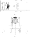
Fig. 3 is a top view of end face positioning of the wheel milling window device of the present invention. -
Fig. 4 is a left view of end face positioning of the wheel milling window device of the present invention. -
Fig. 5 is a schematic diagram of a running state of the wheel milling window device of the present invention. - In which, 1-bottom plate, 2-guide block, 3-clamping slide block, 4-mounting key, 5-hydraulic cylinder, 6-hydraulic pipeline, 7-connecting block, 8-pressure claw, 9-rotating shaft I, 10-rotating shaft II, 11-end face block, 12-mandrel, 13-mandrel seat, 14-locking jackscrew, 15-mandrel height adjusting post, 16-mandrel guide post, 17-mandrel guide post locking screw, 18-locking ring, 19-circumferential positioning post, 20-circumferential slide block.
- Details and working conditions of a specific device provided by the present invention will be described below in combination with the accompanying drawings.
- Embodiment 1: This embodiment discloses a wheel milling window device. The device is composed of a bottom plate 1,
guide blocks 2,clamping slide blocks 3,mounting keys 4, hydraulic cylinders 5,hydraulic pipelines 6, connectingblocks 7,pressure claws 8, rotating shafts I 9, rotating shafts II 10,end face blocks 11, amandrel 12, amandrel seat 13, alocking jackscrew 14, a mandrelheight adjusting post 15, amandrel guide post 16, a mandrel guidepost locking screw 17, alocking ring 18,circumferential positioning posts 19 and circumferential slide blocks 20.The bottom plate 1 is fixed on a machine tool via bolts, the fourguide blocks 2 are fixed on the bottom plate 1 by screws, theclamping slide blocks 3 slide in slots of theguide blocks 2, each end face block 11 can be placed in aclamping slide block 3 and fixed by two screws, the end face blocks 11 and theclamping slide blocks 3 are fixed on the bottom plate 1 by screws, the hydraulic cylinders 5 are fixed on theclamping slide blocks 3 by themounting keys 4 and screws, meanwhile, thehydraulic pipelines 6 are connected and fixed to the hydraulic cylinders 5 via screws, the connectingblocks 7 are fixed at the extension ends of the hydraulic cylinders 5 via threaded connection, thepressure claws 8 are articulated into holes of the connectingblocks 7 via the rotating shafts I 9 and simultaneously articulated to the end face blocks 11 via the rotating shafts II 10, themandrel seat 13 is fixed on the bottom plate 1 via six screws, the mandrelheight adjusting post 15 is in clearance fit in the hole of themandrel seat 13, themandrel guide post 16 is in clearance fit in the hole of the mandrelheight adjusting post 15, thelocking ring 18 and themandrel guide post 16 are locked via threads by the mandrel guidepost locking screw 17, themandrel 12 is fixed on the mandrelheight adjusting post 15 by a screw, and thecircumferential positioning posts 19 can be fixed on thecircumferential slide blocks 20 via threads. - In the working process, the end face blocks 11 scribed with scribed lines in the middle of end face positioning surfaces are fixed together with the
clamping slide blocks 3; theclamping slide blocks 3 can slide in the slots of theguide blocks 2, theguide blocks 2 are scribed with scribed lines corresponding to different wheel sizes, and the positions of the scribed lines are determined according to the outer diameters of the rims of wheels having different sizes; when a wheel of one size is machined, theclamping slide blocks 3 fixed together with the end face blocks 11 can slide in the slots of theguide blocks 2, the scribed lines on the end face blocks 11 are aligned with the scribed lines of corresponding sizes on theguide blocks 2, then the end face blocks 11 and theclamping slide blocks 3 are fixed on the bottom plate 1 by bolts, and end face positioning of the wheel and adjustment of the compression position are thus realized. - The
mandrel 12 corresponding to the diameter of the central hole of the wheel is placed on the mandrelheight adjusting post 15, the extending height of the mandrelheight adjusting post 15 on themandrel seat 13 is adjusted via the screw, the mandrelheight adjusting post 15 is locked by thelocking jackscrew 14 after the height is adjusted, and radial positioning adjustment of the wheel is thus completed. - The
circumferential slide blocks 20 slide to the pitch diameters of bolt holes or mounting holes of the wheel on the bottom plate 1, thecircumferential positioning posts 19 are screwed down with thecircumferential slide blocks 20, thecircumferential positioning posts 19 can penetrate through the bolt holes or mounting holes of the wheel when the wheel is placed on the device, and a circumferential positioning function on the wheel is thus realized. - The wheel is placed on the end face blocks 11, radial positioning of the central hole is realized via the
mandrel 12, the circumferential positioning posts 19 penetrate through the bolt holes or mounting holes, then the extension rods of the hydraulic cylinders 5 move linearly via the hydraulic system to drive the connectingblocks 7 to move, the rotating shafts I 9 are thus driven to move in shaft slots of thepressure claws 8, thepressure claws 8 move circumferentially using the rotating shafts II 10 as circle centers, and the wheel is pressed. The above device is referred to as an experimental group 1. - In this embodiment, further disclosed are the following experimental groups:
- Experimental group 2: other setting is same as that of experimental group 1, but the difference lies in that the end face positioning of the fixture adopts a traditional slide block embedded positioning mode.
- Experimental group 3: other setting is same as that of experimental group 1, but the difference lies in that the central positioning refers to a fixed mandrel seat where the height of the mandrel cannot be adjusted.
-
Experimental groups - The device in this embodiment has the advantages of shortening 7 days for manufacturing a fixture, reducing the cost for machining the fixture by more than 300 CNY, and reducing the time for replacing the fixture from original 2 hours to 20 minutes. The machining flow of the present invention is not obviously difference from the existing machining flow.
- Thus, on the fixture for milling a wheel window, this device can reduce the machining cost, shorten the manufacturing period of the fixture and improve the production efficiency.
Claims (5)
- A wheel milling window fixture, comprising a bottom plate (1) fixed on a machine tool, end face blocks (11) for placing the wheel thereon, a mandrel (12) for radial positioning of the central hole of the wheel and pressure claws (8) for pressing the wheel, characterized in that the wheel milling window fixture comprises guide blocks (2), clamping slide blocks (3), mounting keys (4), hydraulic cylinders (5), hydraulic pipelines (6), connecting blocks (7), rotating shafts I (9) and rotating shafts II (10), arranged in such a way that the four guide blocks (2) are fixed on the bottom plate (1), the clamping slide blocks (3) slide in slots of the guide blocks (2), each end face block (11) is fixed in a clamping slide block (3), the end face blocks (11) and the clamping slide blocks (3) are fixed on the bottom plate (1), the hydraulic cylinders (5) are fixed on the clamping slide blocks (3) by the mounting keys (4), the hydraulic pipelines (6) are fixed on the hydraulic cylinders (5), the connecting blocks (7) are fixed at the extension ends of the hydraulic cylinders (5), the pressure claws (8) are articulated into holes of the connecting blocks (7) via the rotating shafts I (9) and simultaneously articulated to the end face blocks (11) via the rotating shafts II (10); and that the wheel milling window fixture further comprises a mandrel seat (13), a locking jackscrew (14), a mandrel height adjusting post (15), a mandrel guide post (16), a mandrel guide post locking screw (17), a locking ring (18), circumferential positioning posts (19) and circumferential slide blocks (20), arranged in such a way that the mandrel seat (13) is fixed on the bottom plate (1), the mandrel height adjusting post (15) is in clearance fit in the hole of the mandrel seat (13), the mandrel guide post (16) is in clearance fit in the hole of the mandrel height adjusting post (15), the locking ring (18) and the mandrel guide post (16) are locked by the mandrel guide post locking screw (17), the mandrel (12) is fixed on the mandrel height adjusting post (15), and the circumferential positioning posts (19) are fixed on the circumferential slide blocks (20).
- The wheel milling window fixture of claim 1, characterized in that the end face blocks (11) scribed with scribed lines in the middle of end face positioning surfaces are fixed with the clamping slide blocks (3) together; the clamping slide blocks (3) can slide in the slots of the guide blocks (2), the guide blocks (2) are scribed with scribed lines corresponding to different wheel sizes, and the positions of the scribed lines are determined according to the outer diameters of the rims of wheels having different sizes; when a wheel of one size is machined, the clamping slide blocks (3) fixed together with the end face blocks (11) can slide in the slots of the guide blocks (2), the scribed lines on the end face blocks (11) are aligned with the scribed lines of corresponding sizes on the guide blocks (2), then the end face blocks (11) and the clamping slide blocks (3) are fixed on the bottom plate (1) by bolts, and end face positioning of the wheel and adjustment of the compression position are thus realized.
- The wheel milling window fixture of claim 1, characterized in that the mandrel (12) corresponding to the diameter of the central hole of the wheel is placed on the mandrel height adjusting post (15), the extending height of the mandrel height adjusting post (15) on the mandrel seat (13) is adjusted, the mandrel height adjusting post (15) is locked by the locking jackscrew (14) after the height is adjusted, and radial positioning adjustment of the wheel is thus completed.
- The wheel milling window fixture of claim 1, characterized in that the circumferential slide blocks (20) slide to the pitch diameters of bolt holes or mounting holes of the wheel on the bottom plate (1), the circumferential positioning posts (19) are screwed down with the circumferential slide blocks (20), the circumferential positioning posts (19) can penetrate through the bolt holes or mounting holes of the wheel when the wheel is placed on the device, and a circumferential positioning function on the wheel is thus realized.
- The wheel milling window fixture of claim 1, characterized in that the wheel is placed on the end face blocks (11), the mandrel (12) penetrates through the central hole, the circumferential positioning posts (19) penetrate through the bolt holes or mounting holes, then the extension rods of the hydraulic cylinders (5) move linearly via the hydraulic system to drive the connecting blocks (7) to move, the rotating shafts I (9) are thus driven to move in shaft slots of the pressure claws (8), and the pressure claws (8) move circumferentially using the rotating shafts II (10) as circle centers.
Applications Claiming Priority (1)
| Application Number | Priority Date | Filing Date | Title |
|---|---|---|---|
| CN201710746849.7A CN107378576A (en) | 2017-08-27 | 2017-08-27 | A kind of wheel milling window fixture |
Publications (2)
| Publication Number | Publication Date |
|---|---|
| EP3450091A1 EP3450091A1 (en) | 2019-03-06 |
| EP3450091B1 true EP3450091B1 (en) | 2020-05-13 |
Family
ID=60346061
Family Applications (1)
| Application Number | Title | Priority Date | Filing Date |
|---|---|---|---|
| EP18190681.9A Active EP3450091B1 (en) | 2017-08-27 | 2018-08-24 | Wheel milling window fixture |
Country Status (4)
| Country | Link |
|---|---|
| US (1) | US10427257B2 (en) |
| EP (1) | EP3450091B1 (en) |
| CN (1) | CN107378576A (en) |
| MA (1) | MA44570B1 (en) |
Families Citing this family (21)
| Publication number | Priority date | Publication date | Assignee | Title |
|---|---|---|---|---|
| CN108214024A (en) * | 2018-01-23 | 2018-06-29 | 中信戴卡股份有限公司 | A set of forging wheel Milling Machining fixture |
| CN109877280A (en) * | 2019-04-22 | 2019-06-14 | 河北光德精密机械股份有限公司 | Semi-automatic surface layer drenches sand device in a kind of high temperature alloy product preparation process |
| CN112392273A (en) * | 2019-08-13 | 2021-02-23 | 冈室昇志 | Inclination and deviation alignment device for two-joint steel column |
| CN110450976B (en) * | 2019-08-28 | 2022-08-16 | 清远市巨劲科技有限公司 | Unmanned aerial vehicle calibration tool |
| CN110788638B (en) * | 2019-11-01 | 2021-07-23 | 嘉善荣德金属制品股份有限公司 | Cold-heading part processing frock |
| CN110860969B (en) * | 2019-12-13 | 2024-05-14 | 江苏东科复合材料有限公司 | Carbon fiber part polishing equipment with multiple grinding wheels |
| CN111497092B (en) * | 2020-05-26 | 2024-08-09 | 济南伦渠数控机电有限公司 | Material taking and positioning device for numerical control corner cleaning machine |
| CN111922908A (en) * | 2020-08-11 | 2020-11-13 | 灵璧县众泰五金有限公司 | Clamp convenient for assisting omnibearing polishing and omnibearing adjusting method |
| CN111992653A (en) * | 2020-09-16 | 2020-11-27 | 江苏龙城精锻有限公司 | Claw pole part pickup device driven by linear motor |
| CN112025363A (en) * | 2020-10-16 | 2020-12-04 | 安徽理工大学 | Many processing frock clamp of bearing cap |
| CN112178066B (en) * | 2020-11-22 | 2024-09-13 | 中首广金(天津)科技有限公司 | Blind shaft seat convenient to install and used for mining machinery and application method of blind shaft seat |
| CN112496815A (en) * | 2020-12-28 | 2021-03-16 | 河南恒远恒山工业有限公司 | Aerogenerator base anchor disc drilling location clamping device |
| CN113210684B (en) * | 2021-04-09 | 2024-08-30 | 芜湖精艺铜业有限公司 | Adjusting device for copper pipe face milling machine |
| CN113560642B (en) * | 2021-09-27 | 2022-03-18 | 徐州泰和门窗有限公司 | Aluminum alloy door and window processing is with cutting device of adjustable thickness |
| CN114260732A (en) * | 2022-01-25 | 2022-04-01 | 中国铁建重工集团股份有限公司 | Bearing ring radial positioning tool |
| CN114769628B (en) * | 2022-03-09 | 2023-09-01 | 徐州康翔精密制造有限公司 | Transmission shaft turning device |
| CN114734397A (en) * | 2022-03-23 | 2022-07-12 | 中铁建电气化局集团第一工程有限公司 | Catenary hanging ring gripping device for installing catenary dropper |
| CN114932390B (en) * | 2022-04-27 | 2024-03-29 | 浙江华弈汽车零部件科技有限公司 | Intelligent assembly equipment for automobile clutch spring |
| CN115091273A (en) * | 2022-06-02 | 2022-09-23 | 宣城市君诚汽车零部件有限公司 | Surface treatment equipment is used in automobile parts production |
| CN115026611B (en) * | 2022-06-24 | 2023-08-08 | 云南昆船机械制造有限公司 | A compress tightly anchor clamps for quick turning |
| CN116857260B (en) * | 2023-08-15 | 2024-02-13 | 北京金自天成液压技术有限责任公司 | Rolling mill HGC hydraulic cylinder and installation method thereof |
Family Cites Families (14)
| Publication number | Priority date | Publication date | Assignee | Title |
|---|---|---|---|---|
| US5810341A (en) * | 1995-11-02 | 1998-09-22 | Tee-Lok Corporation | Truss table with integrated positioning stops |
| US7204493B1 (en) | 2004-06-03 | 2007-04-17 | Hayes Lemmerz International, Inc. | Lathe chuck with stepped jaws |
| US20070273108A1 (en) | 2006-05-26 | 2007-11-29 | Logansport Matsumoto Company, Inc. | Wheel Chuck |
| US7926797B2 (en) * | 2007-10-17 | 2011-04-19 | Adc Telecommunications, Inc. | Cable splint |
| DE102008014835A1 (en) | 2008-03-07 | 2009-09-10 | Chiron-Werke Gmbh & Co Kg | Machine tool, in particular for wheel machining |
| CN201544059U (en) * | 2009-12-17 | 2010-08-11 | 中信戴卡轮毂制造股份有限公司 | Vertical lathe mandrel seat with adjustable height |
| CN201645183U (en) * | 2010-03-25 | 2010-11-24 | 中信戴卡轮毂制造股份有限公司 | Adjustable mandrel positioning device |
| US8517361B2 (en) * | 2011-02-28 | 2013-08-27 | Eric Pello | Drawer front jig |
| DE202012011628U1 (en) | 2012-12-05 | 2013-01-08 | Siepe Gmbh & Co. Kg | Device for deburring preferably round workpieces made of metal, in particular alloy wheels |
| CN104760452B (en) * | 2015-04-03 | 2017-04-26 | 中信戴卡股份有限公司 | Lettering and overturning clamp of vehicle wheel |
| CN104924169A (en) * | 2015-06-03 | 2015-09-23 | 中信戴卡股份有限公司 | Wheel burring device |
| CN105522425A (en) * | 2016-01-21 | 2016-04-27 | 中信戴卡股份有限公司 | Lathe chuck plate of aluminum alloy hub |
| CN105537634A (en) * | 2016-01-22 | 2016-05-04 | 中信戴卡股份有限公司 | Lathe chuck for aluminum alloy hub |
| CN106737308B (en) * | 2017-02-24 | 2018-10-09 | 中信戴卡股份有限公司 | Flexible clamping device |
-
2017
- 2017-08-27 CN CN201710746849.7A patent/CN107378576A/en active Pending
- 2017-11-09 US US15/808,260 patent/US10427257B2/en active Active
-
2018
- 2018-08-24 MA MA44570A patent/MA44570B1/en unknown
- 2018-08-24 EP EP18190681.9A patent/EP3450091B1/en active Active
Non-Patent Citations (1)
| Title |
|---|
| None * |
Also Published As
| Publication number | Publication date |
|---|---|
| US10427257B2 (en) | 2019-10-01 |
| MA44570B1 (en) | 2020-07-29 |
| CN107378576A (en) | 2017-11-24 |
| EP3450091A1 (en) | 2019-03-06 |
| US20190061078A1 (en) | 2019-02-28 |
Similar Documents
| Publication | Publication Date | Title |
|---|---|---|
| EP3450091B1 (en) | Wheel milling window fixture | |
| CN110253352B (en) | Integrated clamp for clamping and grinding inner ring and outer ring of bearing | |
| CN109079204B (en) | A kind of engine nozzle ring inclined-hole jig | |
| CN202088012U (en) | Mechanical clamping spring collet for holes | |
| CN203184775U (en) | Gear hob jig | |
| CN113927334A (en) | Thin wall hub class part machining device | |
| CN211387238U (en) | Automatic alignment and locking structure for large inner gear ring workpiece | |
| CN110170684B (en) | Tool of drilling jig for drilling circumference of water pump motor end cover | |
| CN214519014U (en) | Lathe test piece positioning fixture | |
| CN212885111U (en) | Motor end cover lathe machining clamp | |
| CN104589112A (en) | Clamp for machining of end faces of cam shafts | |
| CN209831004U (en) | Be applicable to box-like pneumatic adds clamping apparatus of many varieties axle sleeve | |
| CN210475756U (en) | Gear clamp adopting coaxial positioning auxiliary clamping mode | |
| CN101954516A (en) | Gear milling machine tire clamp | |
| CN220112809U (en) | Clamp for step valve machining | |
| CN104646709A (en) | Eccentric disc machining method | |
| CN220699481U (en) | Tool for disassembling and assembling screw ring of cylinder sleeve of drilling pump | |
| CN221640544U (en) | Saddle ring saddle part grinding machine fixture for hand-tearing steel rolling mill | |
| CN220161890U (en) | Special taper expansion mandrel | |
| CN220030793U (en) | Manual expansion type clamp | |
| CN218926301U (en) | Double-expansion clamping device for oil cylinder barrel | |
| CN219484227U (en) | Anti-rotation clamp for rough turning of friction surface of hydraulic torque converter cover assembly | |
| CN209811751U (en) | Shaft sleeve machining clamp | |
| CN204075271U (en) | The pneumatic core clamping device that rises of lathe | |
| CN218947009U (en) | Steering knuckle arm machine tool clamp |
Legal Events
| Date | Code | Title | Description |
|---|---|---|---|
| PUAI | Public reference made under article 153(3) epc to a published international application that has entered the european phase |
Free format text: ORIGINAL CODE: 0009012 |
|
| STAA | Information on the status of an ep patent application or granted ep patent |
Free format text: STATUS: REQUEST FOR EXAMINATION WAS MADE |
|
| 17P | Request for examination filed |
Effective date: 20180824 |
|
| AK | Designated contracting states |
Kind code of ref document: A1 Designated state(s): AL AT BE BG CH CY CZ DE DK EE ES FI FR GB GR HR HU IE IS IT LI LT LU LV MC MK MT NL NO PL PT RO RS SE SI SK SM TR |
|
| AX | Request for extension of the european patent |
Extension state: BA ME |
|
| GRAP | Despatch of communication of intention to grant a patent |
Free format text: ORIGINAL CODE: EPIDOSNIGR1 |
|
| STAA | Information on the status of an ep patent application or granted ep patent |
Free format text: STATUS: GRANT OF PATENT IS INTENDED |
|
| INTG | Intention to grant announced |
Effective date: 20191217 |
|
| GRAS | Grant fee paid |
Free format text: ORIGINAL CODE: EPIDOSNIGR3 |
|
| GRAA | (expected) grant |
Free format text: ORIGINAL CODE: 0009210 |
|
| STAA | Information on the status of an ep patent application or granted ep patent |
Free format text: STATUS: THE PATENT HAS BEEN GRANTED |
|
| AK | Designated contracting states |
Kind code of ref document: B1 Designated state(s): AL AT BE BG CH CY CZ DE DK EE ES FI FR GB GR HR HU IE IS IT LI LT LU LV MC MK MT NL NO PL PT RO RS SE SI SK SM TR |
|
| REG | Reference to a national code |
Ref country code: GB Ref legal event code: FG4D |
|
| REG | Reference to a national code |
Ref country code: CH Ref legal event code: EP |
|
| REG | Reference to a national code |
Ref country code: DE Ref legal event code: R096 Ref document number: 602018004497 Country of ref document: DE |
|
| REG | Reference to a national code |
Ref country code: AT Ref legal event code: REF Ref document number: 1269629 Country of ref document: AT Kind code of ref document: T Effective date: 20200615 |
|
| REG | Reference to a national code |
Ref country code: MA Ref legal event code: VAGR Ref document number: 44570 Country of ref document: MA Kind code of ref document: B1 |
|
| REG | Reference to a national code |
Ref country code: LT Ref legal event code: MG4D |
|
| REG | Reference to a national code |
Ref country code: NL Ref legal event code: MP Effective date: 20200513 |
|
| PG25 | Lapsed in a contracting state [announced via postgrant information from national office to epo] |
Ref country code: FI Free format text: LAPSE BECAUSE OF FAILURE TO SUBMIT A TRANSLATION OF THE DESCRIPTION OR TO PAY THE FEE WITHIN THE PRESCRIBED TIME-LIMIT Effective date: 20200513 Ref country code: LT Free format text: LAPSE BECAUSE OF FAILURE TO SUBMIT A TRANSLATION OF THE DESCRIPTION OR TO PAY THE FEE WITHIN THE PRESCRIBED TIME-LIMIT Effective date: 20200513 Ref country code: PT Free format text: LAPSE BECAUSE OF FAILURE TO SUBMIT A TRANSLATION OF THE DESCRIPTION OR TO PAY THE FEE WITHIN THE PRESCRIBED TIME-LIMIT Effective date: 20200914 Ref country code: IS Free format text: LAPSE BECAUSE OF FAILURE TO SUBMIT A TRANSLATION OF THE DESCRIPTION OR TO PAY THE FEE WITHIN THE PRESCRIBED TIME-LIMIT Effective date: 20200913 Ref country code: SE Free format text: LAPSE BECAUSE OF FAILURE TO SUBMIT A TRANSLATION OF THE DESCRIPTION OR TO PAY THE FEE WITHIN THE PRESCRIBED TIME-LIMIT Effective date: 20200513 Ref country code: GR Free format text: LAPSE BECAUSE OF FAILURE TO SUBMIT A TRANSLATION OF THE DESCRIPTION OR TO PAY THE FEE WITHIN THE PRESCRIBED TIME-LIMIT Effective date: 20200814 Ref country code: NO Free format text: LAPSE BECAUSE OF FAILURE TO SUBMIT A TRANSLATION OF THE DESCRIPTION OR TO PAY THE FEE WITHIN THE PRESCRIBED TIME-LIMIT Effective date: 20200813 |
|
| PG25 | Lapsed in a contracting state [announced via postgrant information from national office to epo] |
Ref country code: RS Free format text: LAPSE BECAUSE OF FAILURE TO SUBMIT A TRANSLATION OF THE DESCRIPTION OR TO PAY THE FEE WITHIN THE PRESCRIBED TIME-LIMIT Effective date: 20200513 Ref country code: HR Free format text: LAPSE BECAUSE OF FAILURE TO SUBMIT A TRANSLATION OF THE DESCRIPTION OR TO PAY THE FEE WITHIN THE PRESCRIBED TIME-LIMIT Effective date: 20200513 Ref country code: BG Free format text: LAPSE BECAUSE OF FAILURE TO SUBMIT A TRANSLATION OF THE DESCRIPTION OR TO PAY THE FEE WITHIN THE PRESCRIBED TIME-LIMIT Effective date: 20200813 Ref country code: LV Free format text: LAPSE BECAUSE OF FAILURE TO SUBMIT A TRANSLATION OF THE DESCRIPTION OR TO PAY THE FEE WITHIN THE PRESCRIBED TIME-LIMIT Effective date: 20200513 |
|
| REG | Reference to a national code |
Ref country code: AT Ref legal event code: MK05 Ref document number: 1269629 Country of ref document: AT Kind code of ref document: T Effective date: 20200513 |
|
| PG25 | Lapsed in a contracting state [announced via postgrant information from national office to epo] |
Ref country code: AL Free format text: LAPSE BECAUSE OF FAILURE TO SUBMIT A TRANSLATION OF THE DESCRIPTION OR TO PAY THE FEE WITHIN THE PRESCRIBED TIME-LIMIT Effective date: 20200513 Ref country code: NL Free format text: LAPSE BECAUSE OF FAILURE TO SUBMIT A TRANSLATION OF THE DESCRIPTION OR TO PAY THE FEE WITHIN THE PRESCRIBED TIME-LIMIT Effective date: 20200513 |
|
| PG25 | Lapsed in a contracting state [announced via postgrant information from national office to epo] |
Ref country code: ES Free format text: LAPSE BECAUSE OF FAILURE TO SUBMIT A TRANSLATION OF THE DESCRIPTION OR TO PAY THE FEE WITHIN THE PRESCRIBED TIME-LIMIT Effective date: 20200513 Ref country code: RO Free format text: LAPSE BECAUSE OF FAILURE TO SUBMIT A TRANSLATION OF THE DESCRIPTION OR TO PAY THE FEE WITHIN THE PRESCRIBED TIME-LIMIT Effective date: 20200513 Ref country code: IT Free format text: LAPSE BECAUSE OF FAILURE TO SUBMIT A TRANSLATION OF THE DESCRIPTION OR TO PAY THE FEE WITHIN THE PRESCRIBED TIME-LIMIT Effective date: 20200513 Ref country code: AT Free format text: LAPSE BECAUSE OF FAILURE TO SUBMIT A TRANSLATION OF THE DESCRIPTION OR TO PAY THE FEE WITHIN THE PRESCRIBED TIME-LIMIT Effective date: 20200513 Ref country code: CZ Free format text: LAPSE BECAUSE OF FAILURE TO SUBMIT A TRANSLATION OF THE DESCRIPTION OR TO PAY THE FEE WITHIN THE PRESCRIBED TIME-LIMIT Effective date: 20200513 Ref country code: SM Free format text: LAPSE BECAUSE OF FAILURE TO SUBMIT A TRANSLATION OF THE DESCRIPTION OR TO PAY THE FEE WITHIN THE PRESCRIBED TIME-LIMIT Effective date: 20200513 Ref country code: EE Free format text: LAPSE BECAUSE OF FAILURE TO SUBMIT A TRANSLATION OF THE DESCRIPTION OR TO PAY THE FEE WITHIN THE PRESCRIBED TIME-LIMIT Effective date: 20200513 Ref country code: DK Free format text: LAPSE BECAUSE OF FAILURE TO SUBMIT A TRANSLATION OF THE DESCRIPTION OR TO PAY THE FEE WITHIN THE PRESCRIBED TIME-LIMIT Effective date: 20200513 |
|
| REG | Reference to a national code |
Ref country code: DE Ref legal event code: R097 Ref document number: 602018004497 Country of ref document: DE |
|
| PG25 | Lapsed in a contracting state [announced via postgrant information from national office to epo] |
Ref country code: SK Free format text: LAPSE BECAUSE OF FAILURE TO SUBMIT A TRANSLATION OF THE DESCRIPTION OR TO PAY THE FEE WITHIN THE PRESCRIBED TIME-LIMIT Effective date: 20200513 Ref country code: PL Free format text: LAPSE BECAUSE OF FAILURE TO SUBMIT A TRANSLATION OF THE DESCRIPTION OR TO PAY THE FEE WITHIN THE PRESCRIBED TIME-LIMIT Effective date: 20200513 |
|
| PLBE | No opposition filed within time limit |
Free format text: ORIGINAL CODE: 0009261 |
|
| STAA | Information on the status of an ep patent application or granted ep patent |
Free format text: STATUS: NO OPPOSITION FILED WITHIN TIME LIMIT |
|
| PG25 | Lapsed in a contracting state [announced via postgrant information from national office to epo] |
Ref country code: MC Free format text: LAPSE BECAUSE OF FAILURE TO SUBMIT A TRANSLATION OF THE DESCRIPTION OR TO PAY THE FEE WITHIN THE PRESCRIBED TIME-LIMIT Effective date: 20200513 |
|
| 26N | No opposition filed |
Effective date: 20210216 |
|
| PG25 | Lapsed in a contracting state [announced via postgrant information from national office to epo] |
Ref country code: LU Free format text: LAPSE BECAUSE OF NON-PAYMENT OF DUE FEES Effective date: 20200824 |
|
| REG | Reference to a national code |
Ref country code: BE Ref legal event code: MM Effective date: 20200831 |
|
| PG25 | Lapsed in a contracting state [announced via postgrant information from national office to epo] |
Ref country code: SI Free format text: LAPSE BECAUSE OF FAILURE TO SUBMIT A TRANSLATION OF THE DESCRIPTION OR TO PAY THE FEE WITHIN THE PRESCRIBED TIME-LIMIT Effective date: 20200513 |
|
| VSFP | Annual fee paid to validation state [announced via postgrant information from national office to epo] |
Ref country code: MA Payment date: 20201001 Year of fee payment: 3 |
|
| PG25 | Lapsed in a contracting state [announced via postgrant information from national office to epo] |
Ref country code: IE Free format text: LAPSE BECAUSE OF NON-PAYMENT OF DUE FEES Effective date: 20200824 Ref country code: BE Free format text: LAPSE BECAUSE OF NON-PAYMENT OF DUE FEES Effective date: 20200831 |
|
| REG | Reference to a national code |
Ref country code: CH Ref legal event code: PL |
|
| PG25 | Lapsed in a contracting state [announced via postgrant information from national office to epo] |
Ref country code: LI Free format text: LAPSE BECAUSE OF NON-PAYMENT OF DUE FEES Effective date: 20210831 Ref country code: CH Free format text: LAPSE BECAUSE OF NON-PAYMENT OF DUE FEES Effective date: 20210831 |
|
| PG25 | Lapsed in a contracting state [announced via postgrant information from national office to epo] |
Ref country code: TR Free format text: LAPSE BECAUSE OF FAILURE TO SUBMIT A TRANSLATION OF THE DESCRIPTION OR TO PAY THE FEE WITHIN THE PRESCRIBED TIME-LIMIT Effective date: 20200513 Ref country code: MT Free format text: LAPSE BECAUSE OF FAILURE TO SUBMIT A TRANSLATION OF THE DESCRIPTION OR TO PAY THE FEE WITHIN THE PRESCRIBED TIME-LIMIT Effective date: 20200513 Ref country code: CY Free format text: LAPSE BECAUSE OF FAILURE TO SUBMIT A TRANSLATION OF THE DESCRIPTION OR TO PAY THE FEE WITHIN THE PRESCRIBED TIME-LIMIT Effective date: 20200513 |
|
| PG25 | Lapsed in a contracting state [announced via postgrant information from national office to epo] |
Ref country code: MK Free format text: LAPSE BECAUSE OF FAILURE TO SUBMIT A TRANSLATION OF THE DESCRIPTION OR TO PAY THE FEE WITHIN THE PRESCRIBED TIME-LIMIT Effective date: 20200513 |
|
| GBPC | Gb: european patent ceased through non-payment of renewal fee |
Effective date: 20220824 |
|
| PG25 | Lapsed in a contracting state [announced via postgrant information from national office to epo] |
Ref country code: GB Free format text: LAPSE BECAUSE OF NON-PAYMENT OF DUE FEES Effective date: 20220824 |
|
| PGFP | Annual fee paid to national office [announced via postgrant information from national office to epo] |
Ref country code: DE Payment date: 20240806 Year of fee payment: 7 |
|
| PGFP | Annual fee paid to national office [announced via postgrant information from national office to epo] |
Ref country code: FR Payment date: 20240829 Year of fee payment: 7 |