CN113560642B - Aluminum alloy door and window processing is with cutting device of adjustable thickness - Google Patents
Aluminum alloy door and window processing is with cutting device of adjustable thickness Download PDFInfo
- Publication number
- CN113560642B CN113560642B CN202111137855.5A CN202111137855A CN113560642B CN 113560642 B CN113560642 B CN 113560642B CN 202111137855 A CN202111137855 A CN 202111137855A CN 113560642 B CN113560642 B CN 113560642B
- Authority
- CN
- China
- Prior art keywords
- fixedly connected
- thickness
- motor
- adjusting
- aluminum alloy
- Prior art date
- Legal status (The legal status is an assumption and is not a legal conclusion. Google has not performed a legal analysis and makes no representation as to the accuracy of the status listed.)
- Active
Links
- 229910000838 Al alloy Inorganic materials 0.000 title claims abstract description 24
- 230000001276 controlling effect Effects 0.000 claims abstract description 36
- 238000003801 milling Methods 0.000 claims abstract description 32
- 230000001105 regulatory effect Effects 0.000 claims abstract description 14
- 238000003754 machining Methods 0.000 claims abstract 3
- 230000005540 biological transmission Effects 0.000 claims description 33
- 230000002146 bilateral effect Effects 0.000 claims description 3
- XAGFODPZIPBFFR-UHFFFAOYSA-N aluminium Chemical compound [Al] XAGFODPZIPBFFR-UHFFFAOYSA-N 0.000 abstract description 46
- 229910052782 aluminium Inorganic materials 0.000 abstract description 46
- 239000000463 material Substances 0.000 description 21
- 230000000694 effects Effects 0.000 description 3
- 238000004519 manufacturing process Methods 0.000 description 3
- 230000006978 adaptation Effects 0.000 description 2
- 238000004140 cleaning Methods 0.000 description 2
- 229910000831 Steel Inorganic materials 0.000 description 1
- 238000001816 cooling Methods 0.000 description 1
- 239000000428 dust Substances 0.000 description 1
- 230000002265 prevention Effects 0.000 description 1
- 238000005507 spraying Methods 0.000 description 1
- 239000010959 steel Substances 0.000 description 1
- XLYOFNOQVPJJNP-UHFFFAOYSA-N water Substances O XLYOFNOQVPJJNP-UHFFFAOYSA-N 0.000 description 1
Images





Classifications
-
- B—PERFORMING OPERATIONS; TRANSPORTING
- B23—MACHINE TOOLS; METAL-WORKING NOT OTHERWISE PROVIDED FOR
- B23C—MILLING
- B23C3/00—Milling particular work; Special milling operations; Machines therefor
-
- B—PERFORMING OPERATIONS; TRANSPORTING
- B23—MACHINE TOOLS; METAL-WORKING NOT OTHERWISE PROVIDED FOR
- B23C—MILLING
- B23C9/00—Details or accessories so far as specially adapted to milling machines or cutter
-
- B—PERFORMING OPERATIONS; TRANSPORTING
- B23—MACHINE TOOLS; METAL-WORKING NOT OTHERWISE PROVIDED FOR
- B23Q—DETAILS, COMPONENTS, OR ACCESSORIES FOR MACHINE TOOLS, e.g. ARRANGEMENTS FOR COPYING OR CONTROLLING; MACHINE TOOLS IN GENERAL CHARACTERISED BY THE CONSTRUCTION OF PARTICULAR DETAILS OR COMPONENTS; COMBINATIONS OR ASSOCIATIONS OF METAL-WORKING MACHINES, NOT DIRECTED TO A PARTICULAR RESULT
- B23Q7/00—Arrangements for handling work specially combined with or arranged in, or specially adapted for use in connection with, machine tools, e.g. for conveying, loading, positioning, discharging, sorting
Landscapes
- Engineering & Computer Science (AREA)
- Mechanical Engineering (AREA)
- Milling Processes (AREA)
Abstract
The utility model discloses a thickness-adjustable cutting device for aluminum alloy door and window machining, relates to the technical field of aluminum alloy machining, and solves the problem that the existing device is inconvenient to mill the top of an aluminum product to adjust the thickness of the aluminum product. A thickness-adjustable cutting device for processing aluminum alloy doors and windows comprises a front reciprocating lead screw and a rear reciprocating lead screw, wherein the front reciprocating lead screw and the rear reciprocating lead screw are fixedly connected to the top surface of a thickness regulating and controlling platform; the horizontal reciprocating screw is fixedly connected to the top of the ball nut seat of the front and rear reciprocating screws; the vertical reciprocating screw is fixedly connected to the top of the horizontal reciprocating screw ball nut seat; the milling motor is fixedly connected to the front end of the vertical reciprocating screw ball nut seat; the milling cutter disc is coaxially connected and arranged at the bottom end of a rotating shaft of the milling motor; through the cooperation of the control part control multiunit reciprocating screw, can make the control mill the facing cutter of motor bottom carry out diversified translation, be convenient for mill the aluminum product of different width, be convenient for control its thickness.
Description
Technical Field
The utility model relates to the technical field of aluminum alloy processing, in particular to a thickness-adjustable cutting device for processing aluminum alloy doors and windows.
Background
In the aluminum alloy door and window course of working, need cut the aluminum alloy strip frame, the thickness of raw and other materials is not convenient for adjust to current device, needs the cutting device of an adjustable thickness for aluminum alloy door and window processing now.
Through retrieving for example, patent No. CN211278574U discloses a door and window cutting device for aluminum alloy plastic-steel door and window manufacturing, including desktop, backup pad and fixed plate, bearing and hinge, the activity groove has been seted up to desktop upper end outer wall, the motor is installed to desktop lower extreme outer wall, motor one side outer wall is provided with the saw bit, desktop upper end outer wall is provided with the apron, the through-hole has been seted up to apron lower extreme outer wall one side, the apron is rotated with the desktop through the hinge and is linked, the desktop deviates from activity groove one side outer wall symmetry and has seted up the spout, the spout upper end is provided with the backup pad, first screw has been seted up to backup pad upper end outer wall one side symmetry.
For another example, patent No. CN213888398U discloses a cutting device is used in aluminum alloy door and window frame production, concretely relates to aluminum alloy door and window production technical field, including workstation and base, the inside of workstation is provided with the base, the intermediate position department on workstation top is provided with logical groove, the top that leads to the groove is provided with positioning mechanism, the inside one side of base is provided with inhales bits mechanism, the inside opposite side of base is provided with removes cutting mechanism. According to the utility model, the flexible pipe, the exhaust fan, the scrap collecting cover, the elastic clamping block, the air guide opening and the filter piece are arranged, when cutting is carried out, scraps are easy to fall into the base from the through groove and the trough, so that the scrap collecting cover is arranged, the scraps are sucked into the scrap collecting cover by the exhaust fan, the filter piece is buckled inside the air guide opening to prevent the scraps from leaking, the filter piece is in a detachable design and can be periodically taken down for cleaning and blockage prevention, the mechanism can reduce the dust covering condition of a working area table board by the scraps in a flying way, and the complexity of cleaning work is reduced.
Based on the aforesaid, traditional cutting device for aluminum alloy door and window processing generally is single workstation structure, does not set up and can support the aluminum product and carry out the fixed structure of centre gripping after carrying out vertical translation, the height that the control aluminum product top of being not convenient for exposes, it mills in order to adjust its thickness to the aluminum product top to be not convenient for, does not set up the structure that is convenient for mill the aluminum product of different width, does not set up the aluminum product that can the different width of adaptation and carries out the structure of translation transmission, is not convenient for adjust the cutting position.
Therefore, the existing requirements are not met, and the thickness-adjustable cutting device for processing the aluminum alloy doors and windows is provided.
Disclosure of Invention
Problem (A)
The utility model aims to provide a thickness-adjustable cutting device for processing aluminum alloy doors and windows, and aims to solve the problems that the traditional cutting device for processing aluminum alloy doors and windows, which is provided in the background art, is generally of a single workbench structure, is not provided with a structure capable of supporting an aluminum material to vertically translate and then clamp and fix, is inconvenient to control the exposed height of the top of the aluminum material, mill the top of the aluminum material to adjust the thickness of the aluminum material, mill aluminum materials with different widths, adapt to aluminum materials with different widths and translate and transmit, and is inconvenient to adjust the cutting position.
Technical scheme
In order to achieve the purpose, the utility model provides the following technical scheme: a thickness-adjustable cutting device for processing aluminum alloy doors and windows comprises a thickness adjusting and controlling table;
the thickness adjusting and controlling platform is provided with a base at the bottom and comprises two groups of height adjusting and fixing structures which are fixedly connected to the left side and the right side of the thickness adjusting and controlling platform;
the height-adjusting fixing structure comprises a right extending table, a vertical hydraulic cylinder, a supporting plate, a bearing frame and a clamping structure, the right extending table is fixedly connected to the right end of the thickness adjusting and controlling table, the top of the right extending table is fixedly connected with the bearing frame, the vertical hydraulic cylinder is fixedly connected to the bottom of the right extending table, a telescopic part of the vertical hydraulic cylinder vertically penetrates through the inner side of the middle part of the bearing frame, the top end of the telescopic part of the vertical hydraulic cylinder is fixedly connected with the supporting plate, and the clamping structure is fixedly connected to the top of the bearing frame;
the top of the thickness regulating table is connected with a thickness regulating structure;
the left end of the thickness adjusting and controlling table is fixedly connected with a feeding structure;
the cutting table is fixedly connected to the front end of the right side of the thickness adjusting and controlling table.
Preferably, the clamping structure further comprises: the square shell is fixedly connected to the top end of the bearing frame; the inner side of the square shell is rotatably connected with a transmission gear, the transmission gear is divided into an upper layer and a lower layer, the inner side of the transmission gear is provided with a double-sided rack through meshing transmission, the front end of the double-sided rack is fixedly connected with a clamping plate, and the right end of the transmission gear is provided with a worm wheel through coaxial connection.
Preferably, the inner side of the square shell is rotatably connected with a worm, the bottom of the worm is meshed with a worm wheel, the rear end of the worm is provided with a bevel gear set A through coaxial connection, the right side of the square shell is fixedly connected with a servo motor, and a rotating shaft of the servo motor is coaxially connected with the right end of the bevel gear set A.
Preferably, the thickness regulating structure includes:
the front and back reciprocating screw rods are arranged into two groups and fixedly connected to the top surface of the thickness regulating and controlling platform;
and the horizontal reciprocating screw is fixedly connected to the top of the ball nut seat of the front and rear reciprocating screws.
Preferably, the thickness regulating structure further comprises:
the vertical reciprocating screw is fixedly connected to the top of the horizontal reciprocating screw ball nut seat;
the milling motor is fixedly connected to the front end of the vertical reciprocating screw ball nut seat;
and the milling cutter disc is arranged at the bottom end of the rotating shaft of the milling motor through coaxial connection.
Preferably, the thickness regulating structure further comprises:
the pressure pump is fixedly connected to the top of the thickness regulating and controlling table;
the rear ends of the two-side inclined pipes are connected with the pressure pump, and the front ends of the two-side inclined pipes are fixedly connected to the left side and the right side of the milling motor.
Preferably, feeding structure left end fixedly connected with spout, both ends fixedly connected with curb plate around the feeding structure, curb plate medial surface fixedly connected with reset spring, the inboard fixedly connected with slider of reset spring, slider right-hand member and spout sliding connection, the slider top is rotated and is connected and be provided with the centre gripping roller.
Preferably, the bottom end of the clamping roller is provided with a bottom gear through coaxial connection, the bottom gears are in chain transmission, the bottom end of the bottom gear is provided with a bevel gear set B through coaxial connection, the bottom of the sliding block is rotatably connected with a bottom shaft rod, the bevel gear set B is coaxially connected with the right side of the bottom shaft rod, the left end of the bottom shaft rod is provided with a square rod through coaxial connection, and the left side of the square rod is sleeved with a square groove pipe.
Preferably, the right side of the square groove pipe is provided with a first-stage gear through coaxial connection, the bottom of the left-side sliding block is rotatably connected with a second-stage gear, the second-stage gear is meshed with the first-stage gear, the left side of the second-stage gear is provided with a bevel gear set C through coaxial connection, and the top of the bevel gear set C is coaxially connected with the bottom of the bottom gear.
Preferably, the cutting table comprises:
the control part is fixedly connected to the top surface of the cutting table;
the translation hydraulic cylinder is fixedly connected to the right side of the top of the cutting table;
the angle adjusting motor is fixedly connected to the front end of the telescopic part of the translation hydraulic cylinder;
the sliding rail is fixedly connected to the top of the cutting table, and the top of the sliding rail is in sliding connection with the bottom of the angle adjusting motor;
the cutting saw is arranged at the front end of the rotating shaft of the angle modulation motor through coaxial connection.
(III) advantageous effects
1. According to the aluminum product clamping device, the clamping structure is arranged, the servo motor is controlled to operate through the control part, the rotating shaft of the servo motor can drive the coaxial bevel gear group A to rotate, the worm coaxial with the bevel gear group A can be rotated to drive the meshed worm gear to rotate, the transmission gear coaxial with the worm gear can be rotated, the double-sided rack meshed with the transmission gear can be translated, the clamping plate at the tail end of the double-sided rack can be translated, the aluminum product on the inner side of the clamping plate can be clamped and fixed, the aluminum product supported by the supporting plate at the top end of the telescopic part of the vertical hydraulic cylinder can be clamped and fixed after being vertically translated through the matching of the clamping structure and the vertical hydraulic cylinder, the exposed height of the top of the aluminum product can be conveniently controlled, and the top of the aluminum product can be milled to adjust the thickness of the aluminum product.
2. The milling machine is characterized in that a control part is arranged on the milling machine body, a plurality of groups of reciprocating lead screws are arranged on the milling machine body, a control part is arranged on the control part, a plurality of groups of reciprocating lead screws are arranged on the control part, and a plurality of groups of reciprocating lead screws are arranged on the control part.
3. The utility model also arranges a feeding structure, after the strip aluminum material is placed inside the two rows of clamping rollers, the two groups of sliding blocks are pressed by the reset springs on the opposite outer sides of the two groups of sliding blocks, so that the two groups of sliding blocks can translate inwards, the two rows of clamping rollers can clamp the two sides of the aluminum material, the square rods slide inside the square groove pipes, the space between the two groups of sliding blocks can be adapted, the control part controls the motor to operate, so that the motor can drive the bottom gears to rotate, the same row of bottom gears can rotate in the same direction through chain transmission, the bottom gears can drive the square rods to rotate through the transmission of the bevel gear set B, the square rods drive the square groove pipes which are connected outside the square groove pipes to rotate, the square groove pipes can drive the primary gears which are coaxial with the square groove pipes to rotate, and further drive the secondary gears which are meshed with the tops of the primary gears to rotate, so that the bevel gear set C which is coaxial with the secondary gears rotates, thereby make the coaxial bottom gear of left side slider bottom in bevel gear group C top carry out with the rotation of right side bottom gear opposite direction to can make two rows of grip rollers at two sets of slider tops carry out the rotation of opposite direction, can make the aluminum product of the different width of grip roller adaptation and carry out translation transmission, the adjustment cutting position of being convenient for.
Drawings
FIG. 1 is a schematic top view of an embodiment of the present invention;
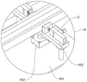
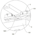
FIG. 2 is an enlarged view of a portion of A in FIG. 1 according to a first embodiment of the present invention;
FIG. 3 is an enlarged view of a portion B of FIG. 1 according to one embodiment of the present invention;
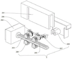
FIG. 4 is a schematic perspective exploded view of a clamping structure according to an embodiment of the present invention;
FIG. 5 is a schematic bottom perspective view of a second embodiment of the present invention;
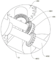
FIG. 6 is an enlarged view of a portion of C in FIG. 5 according to a second embodiment of the present invention;
FIG. 7 is an enlarged view of a portion of D in FIG. 5 according to a second embodiment of the present invention;
FIG. 8 is a schematic rear side three-dimensional structure of the third embodiment of the present invention;
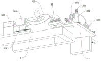
FIG. 9 is a schematic bottom perspective view of the left side of the display device according to the present invention;
FIG. 10 is an enlarged partial view of E in FIG. 9 according to one embodiment of the present invention;
in fig. 1 to 10, the correspondence between the part names or lines and the reference numbers is:
1. a thickness adjusting and controlling table;
101. a right extension stage; 102. a vertical hydraulic cylinder; 1021. a support plate; 103. a receiving frame;
2. a clamping structure;
201. a square shell; 202. a clamping plate; 203. a double-sided rack; 204. a transmission gear; 205. a worm gear; 206. a worm; 207. a bevel gear set A; 208. a servo motor;
3. a reciprocating screw rod back and forth;
301. a horizontally reciprocating lead screw; 302. a vertically reciprocating lead screw; 303. milling a motor; 3031. a milling cutter disc; 304. a pressure pump; 3041. a bilateral inclined tube;
4. a feed structure;
401. a chute; 402. a side plate; 4021. a return spring; 403. a slider; 4031. a grip roller; 404. a bottom gear; 4041. a bevel gear set B; 405. a bottom shaft lever; 4051. a square bar; 4052. a square groove pipe; 4053. a primary gear; 406. a secondary gear; 4061. a bevel gear set C;
5. cutting table;
501. a control unit; 502. a translation hydraulic cylinder; 503. an angle adjusting motor; 504. a slide rail; 505. and (4) cutting and sawing.
Detailed Description
The technical solutions in the embodiments of the present invention will be clearly and completely described below with reference to the drawings in the embodiments of the present invention, and it is obvious that the described embodiments are only a part of the embodiments of the present invention, and not all of the embodiments.
In the description of the present invention, "a plurality" means two or more unless otherwise specified; the terms "upper", "lower", "left", "right", "inner", "outer", "front", "rear", "head", "tail", and the like, indicate orientations or positional relationships based on the orientations or positional relationships shown in the drawings, are only for convenience in describing and simplifying the description, and do not indicate or imply that the device or element referred to must have a particular orientation, be constructed in a particular orientation, and be operated, and thus, should not be construed as limiting the utility model. Furthermore, the terms "first," "second," "third," and the like are used for descriptive purposes only and are not to be construed as indicating or implying relative importance.
In the description of the present invention, it is to be noted that, unless otherwise explicitly specified or limited, the terms "connected" and "connected" are to be interpreted broadly, e.g., as being fixed or detachable or integrally connected; can be mechanically or electrically connected; may be directly connected or indirectly connected through an intermediate. The specific meanings of the above terms in the present invention can be understood in specific cases to those skilled in the art.
Referring to fig. 1 to 4 and 9 to 10, a first embodiment of the present invention: a thickness-adjustable cutting device for processing aluminum alloy doors and windows comprises a thickness adjusting and controlling table 1; the bottom of the thickness adjusting and controlling table 1 is provided with a base, the thickness adjusting and controlling table 1 comprises two groups of height adjusting and fixing structures, and the height adjusting and fixing structures are fixedly connected to the left side and the right side of the thickness adjusting and controlling table 1; the height-adjusting fixing structure comprises a right extending table 101, a vertical hydraulic cylinder 102, a supporting plate 1021, a bearing frame 103 and a clamping structure 2, the right extending table 101 is fixedly connected to the right end of the thickness adjusting and controlling table 1, the top of the right extending table 101 is fixedly connected with the bearing frame 103, the vertical hydraulic cylinder 102 is fixedly connected to the bottom of the right extending table 101, an expansion part of the vertical hydraulic cylinder 102 vertically penetrates through the inner side of the middle part of the bearing frame 103, the supporting plate 1021 is fixedly connected to the top end of the expansion part of the vertical hydraulic cylinder 102, the vertical hydraulic cylinder 102 is electrically connected with the control part 501, and the clamping structure 2 is fixedly connected to the top of the bearing frame 103; the top of the thickness regulating and controlling platform 1 is connected with a thickness regulating and controlling structure; the left end of the thickness adjusting and controlling table 1 is fixedly connected with a feeding structure 4, and the front end of the right side of the thickness adjusting and controlling table 1 is fixedly connected with a cutting table 5.
As shown in fig. 1, the cutting table 5 includes: the control part 501, the control part 501 is fixedly connected with the top surface of the cutting table 5; the translation hydraulic cylinder 502 is fixedly connected to the right side of the top of the cutting table 5; the angle adjusting motor 503 is fixedly connected to the front end of the telescopic part of the translational hydraulic cylinder 502, and is electrically connected with the control part 501; the sliding rail 504 is fixedly connected to the top of the cutting table 5, and the top of the sliding rail 504 is slidably connected with the bottom of the angle adjusting motor 503; the cutting saw 505 is arranged at the front end of the rotating shaft of the angle adjusting motor 503 through coaxial connection, the cutting saw 505 is electrically connected with the control part 501, the angle adjusting motor 503 is controlled by the control part 501 to operate to drive the cutting saw 505 with the coaxial front end of the rotating shaft to carry out angle adjustment, and then the control part 501 controls the translation hydraulic cylinder 502 to operate, so that the telescopic part of the cutting saw can drive the cutting saw 505 to translate back and forth, and the aluminum material with the adjusted thickness can be cut at multiple angles.
Feeding structure 4 left end fixedly connected with spout 401, both ends fixedly connected with curb plate 402 around feeding structure 4, curb plate 402 medial surface fixedly connected with reset spring 4021, the inboard fixedly connected with slider 403 of reset spring 4021, slider 403 right-hand member and spout 401 sliding connection, the slider 403 top is rotated and is connected and be provided with centre gripping roller 4031.
As shown in fig. 4, the holding structure 2 further includes: the square shell 201, the square shell 201 is fixedly connected to the top end of the bearing frame 103; a transmission gear 204 is rotatably connected to the inner side of the square shell 201, the transmission gear 204 is divided into an upper layer and a lower layer, each layer is divided into two groups, a double-sided rack 203 is arranged on the inner side of the transmission gear 204 through meshing transmission, a clamping plate 202 is fixedly connected to the front end of the double-sided rack 203, and a worm gear 205 is coaxially connected to the right end of the transmission gear 204; the inner side of the square shell 201 is rotatably connected with a worm 206, the bottom of the worm 206 is meshed with a worm wheel 205, the rear end of the worm 206 is coaxially connected with a bevel gear group A207, the right side of the square shell 201 is fixedly connected with a servo motor 208, the rotating shaft of the servo motor 208 is coaxially connected with the right end of the bevel gear group A207, the electric property of the worm is connected with a control part 501, the servo motor 208 is controlled by the control part 501 to operate, the rotating shaft of the servo motor 208 can drive the coaxial bevel gear group A207 to rotate, so that the worm 206 coaxial with the bevel gear group A207 can rotate, the meshed worm wheel 205 can be driven to rotate, a transmission gear 204 coaxial with the worm wheel 205 can rotate, a double-sided rack 203 meshed with the transmission gear 204 can be enabled to translate, a clamping plate 202 at the tail end of the double-sided rack 203 can be enabled to translate, and the aluminum material at the inner side of the clamping plate 202 can be clamped and fixed, through the cooperation of the clamping structure 2 and the vertical hydraulic cylinder 102, the aluminum material can be supported by the support plate 1021 at the top end of the telescopic part of the vertical hydraulic cylinder 102 to be vertically translated and then clamped and fixed, so that the exposed height of the top of the aluminum material can be conveniently controlled, and the aluminum material can be conveniently milled.
In a second embodiment, as shown in fig. 8, the thickness adjusting structure includes: the front and back reciprocating screw rods 3 are arranged into two groups, are fixedly connected to the top surface of the thickness adjusting and controlling table 1, and are electrically connected with the control part 501; the horizontal reciprocating screw 301, the horizontal reciprocating screw 301 is fixedly connected to the top of the ball nut seat of the front and back reciprocating screw 3, and the electrical property of the horizontal reciprocating screw 301 is connected with the control part 501; the vertical reciprocating screw 302, the vertical reciprocating screw 302 is fixedly connected to the top of the ball nut seat of the horizontal reciprocating screw 301, and the electrical property of the vertical reciprocating screw is connected with the control part 501; the milling motor 303, the milling motor 303 is fixedly connected to the front end of the ball nut seat of the vertical reciprocating screw 302, and the electrical property of the milling motor 303 is connected with the control part 501; the milling cutter 3031 is coaxially connected with the bottom end of the rotating shaft of the milling motor 303; a pressure pump 304, wherein the pressure pump 304 is fixedly connected to the top of the thickness adjusting and controlling table 1, and the electrical property of the pressure pump is connected with the control part 501; the double-side inclined pipe 3041, the middle of the double-side inclined pipe 3041 is a three-way pipe structure, the rear end thereof is connected with a pressure pump 304, the front end thereof is fixedly connected with the left and right sides of a milling motor 303, the bottom of the front end thereof is inclined towards the inner side of a milling cutter head 3031, the flying of aluminum scraps and the cooling of a cutter can be reduced by spraying water to the milling cutter head 3031, the control part 501 controls two groups of reciprocating screw rods 3 to operate, so that a horizontal reciprocating screw rod 301 at the top of a ball nut seat can be translated back and forth, the control part 501 controls the horizontal reciprocating screw rod 301 to operate, so that a vertical reciprocating screw rod 302 at the top can be translated left and right, the control part 501 controls the vertical reciprocating screw rod 302 to operate, so that the milling motor 303 at the front end of the ball nut seat can be vertically displaced, and the milling cutter head 3031 at the bottom of the milling motor 303 can be controlled to translate in multiple directions by the cooperation of the plurality of reciprocating screw rods, the aluminum product with different widths can be milled conveniently, and the thickness of the aluminum product can be controlled conveniently.
In the third embodiment, as shown in fig. 5 to 7, the bottom ends of the pinch rollers 4031 are provided with bottom gears 404 through coaxial connection, the bottom gears 404 are driven by a chain, the bottom ends of the bottom gears 404 are provided with bevel gear sets B4041 through coaxial connection, the bottom of the sliding block 403 is rotatably connected with a bottom shaft rod 405, the bevel gear sets B4041 are coaxially connected with the right side of the bottom shaft rod 405, the left end of the bottom shaft rod 405 is provided with a square rod 4051 through coaxial connection, and the left side of the square rod 4051 is sleeved with a square groove tube 4052; a first-level gear 4053 is coaxially connected and arranged on the right side of the square groove pipe 4052, a second-level gear 406 is rotatably connected and arranged at the bottom of the left-side sliding block 403, the second-level gear 406 is meshed with the first-level gear 4053, a bevel gear group C4061 is coaxially connected and arranged on the left side of the second-level gear 406, the top of the bevel gear group C4061 is coaxially connected with the bottom of the bottom gear 404, the number of the sliding blocks 403 is two, the number of the clamping rollers 4031 is three, the number of the top of each sliding block 403 is three, a bevel gear group B4041 is coaxially connected and arranged at the bottom of the front-end bottom gear 404 at the bottom of the right-side sliding block 403, a bevel gear group C4061 is coaxially connected and arranged at the bottom of the front-end bottom of the left-side sliding block 403, the left end of the square groove pipe 4052 is hinged and connected with the bottom of the left-side sliding block 403, the electric motor is electrically connected with the control part 501, and the rotating shaft of the bottom gear 404 at the rear end below the sliding block 403 is coaxial, after the strip-shaped aluminum material is placed inside the two rows of clamping rollers 4031, the two groups of sliding blocks 403 are pressed by the reset springs 4021 on the opposite outer sides, so that the two groups of sliding blocks 403 can translate inwards, the two rows of clamping rollers 4031 can clamp two sides of the aluminum material, the square rods 4051 can slide on the inner sides of the square groove tubes 4052, the distances between the two groups of sliding blocks 403 can be adapted, the control part 501 controls the motor to operate, so that the motor can drive the bottom gears 404 to rotate, the same row of bottom gears 404 can rotate in the same direction through chain transmission, the bottom gears 404 can drive the square rods 4051 to rotate through the transmission of the bevel gear groups B4041, the square rods 4051 drive the square groove tubes 4052 which are connected outside to rotate, the square groove tubes 4052 can drive the primary gears 4053 which are coaxial with the square groove tubes 4052 to rotate, so that the secondary gears 406 meshed with the tops of the primary gears 4053 rotate, and the bevel gear groups C4061 which are coaxial with the secondary gears 406 rotate, therefore, the bottom gear 404 at the bottom of the left slider 403 with the top coaxial with the bevel gear group C4061 rotates in the direction opposite to the direction of the right bottom gear 404, so that the two rows of clamping rollers 4031 at the top of the two groups of sliders 403 rotate in the opposite direction, and aluminum materials with different widths clamped inside the clamping rollers 4031 can be subjected to translation transmission.
The working principle is as follows:
when the device is used, after the strip-shaped aluminum material is placed inside the two rows of clamping rollers 4031, the two groups of sliding blocks 403 are pressed by the reset springs 4021 on the opposite outer sides of the two groups of sliding blocks 403, so that the two groups of sliding blocks 403 can translate inwards, the two rows of clamping rollers 4031 can clamp two sides of the aluminum material, the square rods 4051 can slide on the inner sides of the square grooved tubes 4052, the distances between the two groups of sliding blocks 403 can be adapted, the control part 501 controls the motor to operate, so that the motor can drive the bottom gears 404 to rotate, the same row of bottom gears 404 can rotate in the same direction through chain transmission, the bottom gears 404 can drive the square rods 4051 to rotate through transmission of the bevel gears B4041, the square rods 4051 drive the square grooved tubes 4052 which are connected outside to rotate, the square grooved tubes 4052 can drive the primary gears 4053 which are coaxial with the square grooved tubes 4052 to rotate, so that the secondary gears 406 meshed with the tops of the primary gears 4053 rotate, and the bevel gears C4061 which are coaxial with the secondary gears 406 rotate, so that the bottom gear 404 at the bottom of the left slider 403 with the top coaxial with the bevel gear group C4061 rotates in the opposite direction to the right bottom gear 404, so that the two rows of clamping rollers 4031 at the top of the two groups of sliders 403 rotate in the opposite direction, the aluminum material clamped by the inner sides of the clamping rollers 4031 can be transmitted in a translation manner, the servo motor 208 is controlled by the control part 501 to operate, the rotating shaft of the servo motor 208 can drive the coaxial bevel gear group a207 to rotate, the worm 206 coaxial with the bevel gear group a207 can rotate, the worm gear 205 can drive the worm gear to rotate, the transmission gear 204 coaxial with the worm gear 205 can rotate, the double-sided rack 203 meshed with the transmission gear 204 can be translated, the clamping plate 202 at the tail end of the double-sided rack 203 can be translated, the aluminum material inside the clamping plate 202 can be clamped and fixed, and is matched with the vertical hydraulic cylinder 102 through the clamping structure 2, the aluminum product can be supported by a supporting plate 1021 at the top end of a telescopic part of a vertical hydraulic cylinder 102 to be vertically translated and then clamped and fixed, the exposed height of the top of the aluminum product can be conveniently controlled, the aluminum product can be conveniently milled, two groups of front and back reciprocating lead screws 3 are controlled by a control part 501 to operate, the horizontal reciprocating lead screws 301 at the top of ball nut seats can be horizontally translated back and forth, the vertical reciprocating lead screws 302 at the top of the control part can be horizontally translated left and right by controlling the horizontal reciprocating lead screws 301 to operate by the control part 501, the milling motor 303 at the front end of the ball nut seats can be vertically displaced by controlling the operation of the vertical reciprocating lead screws 302 by the control part 501, the milling cutter head 3031 at the bottom of the milling motor 303 can be controlled to be horizontally translated in multiple directions by matching of the multiple groups of reciprocating lead screws, the aluminum products with different widths can be conveniently milled, the thickness of the aluminum product can be conveniently controlled, after the thickness of the aluminum product is regulated after the clamping of a clamping structure 2 is stopped, after the aluminum product is transmitted to the right side through the clamping roller 4031, the control part 501 controls the angle adjusting motor 503 to operate to drive the cutting saw 505 with the coaxial front end of the rotating shaft to perform angle adjustment, and the control part 501 controls the translation hydraulic cylinder 502 to operate, so that the telescopic part of the cutting saw can drive the cutting saw 505 to perform forward and backward translation, and the aluminum product with the adjusted thickness can be cut at multiple angles.
It will be evident to those skilled in the art that the utility model is not limited to the details of the foregoing illustrative embodiments, and that the present invention may be embodied in other specific forms without departing from the spirit or essential attributes thereof. The present embodiments are therefore to be considered in all respects as illustrative and not restrictive, the scope of the utility model being indicated by the appended claims rather than by the foregoing description, and all changes which come within the meaning and range of equivalency of the claims are therefore intended to be embraced therein. Any reference sign in a claim should not be construed as limiting the claim concerned.
Claims (5)
1. The utility model provides an aluminum alloy door and window processing is with cutting device of adjustable thickness which characterized in that: comprises a thickness adjusting and controlling table (1); the thickness adjusting and controlling platform comprises a thickness adjusting and controlling platform (1), wherein a base is arranged at the bottom of the thickness adjusting and controlling platform (1), the thickness adjusting and controlling platform (1) comprises two groups of height adjusting and fixing structures, and the height adjusting and fixing structures are fixedly connected to the left side and the right side of the thickness adjusting and controlling platform (1); the height-adjusting fixing structure comprises a right extending platform (101), a vertical hydraulic cylinder (102), a supporting plate (1021), a bearing frame (103) and a clamping structure (2), the right extending platform (101) is fixedly connected to the right end of the thickness adjusting and controlling platform (1), the top of the right extending platform (101) is fixedly connected with the bearing frame (103), the vertical hydraulic cylinder (102) is fixedly connected to the bottom of the right extending platform (101), a telescopic part of the vertical hydraulic cylinder (102) vertically penetrates through the inner side of the middle part of the bearing frame (103), the top end of the telescopic part of the vertical hydraulic cylinder (102) is fixedly connected with the supporting plate (1021), and the clamping structure (2) is fixedly connected to the top of the bearing frame (103); the top of the thickness adjusting and controlling platform (1) is connected with a thickness adjusting and controlling structure; the left end of the thickness adjusting and controlling platform (1) is fixedly connected with a feeding structure (4); the cutting table (5) is fixedly connected to the front end of the right side of the thickness adjusting and controlling table (1); the clamping structure (2) further comprises: the square shell (201), the square shell (201) is fixedly connected to the top end of the bearing frame (103);
a worm (206) is rotatably connected to the inner side of the square shell (201), the bottom of the worm (206) is meshed with a worm wheel (205), a bevel gear set A (207) is coaxially connected to the rear end of the worm (206), a servo motor (208) is fixedly connected to the right side of the square shell (201), and a rotating shaft of the servo motor (208) is coaxially connected with the right end of the bevel gear set A (207);
the thickness regulating structure includes: the front and back reciprocating screw rods (3) are arranged into two groups and fixedly connected to the top surface of the thickness adjusting and controlling platform (1); the horizontal reciprocating screw rod (301), the horizontal reciprocating screw rod (301) is fixedly connected to the top of the ball nut seat of the front and back reciprocating screw rod (3);
the thickness regulating structure further includes: the vertical reciprocating lead screw (302), the vertical reciprocating lead screw (302) is fixedly connected to the top of the ball nut seat of the horizontal reciprocating lead screw (301); the milling motor (303), the milling motor (303) is fixedly connected to the front end of the ball nut seat of the vertical reciprocating screw (302); the milling cutter head (3031), the milling cutter head (3031) is coaxially connected with the bottom end of the rotating shaft of the milling motor (303);
the thickness regulating structure further includes: the pressurizing pump (304), the pressurizing pump (304) is fixedly connected to the top of the thickness adjusting and controlling table (1); the rear end of the bilateral inclined pipe (3041) is connected with the pressure pump (304), and the front end of the bilateral inclined pipe is fixedly connected with the left side and the right side of the milling motor (303);
the cutting table (5) comprises: the control part (501), the control part (501) is fixedly connected with the top surface of the cutting table (5); the translation hydraulic cylinder (502), the translation hydraulic cylinder (502) is fixedly connected to the right side of the top of the cutting table (5); the angle adjusting motor (503) is fixedly connected to the front end of the telescopic part of the translation hydraulic cylinder (502); the sliding rail (504), the sliding rail (504) is fixedly connected to the top of the cutting table (5), and the top of the sliding rail is connected with the bottom of the angle adjusting motor (503) in a sliding manner; the angle adjusting motor (503) is arranged at the front end of the rotating shaft of the angle adjusting motor (505), and the cutting saw (505) is coaxially connected with the rotating shaft of the angle adjusting motor (503).
2. The thickness-adjustable cutting device for processing the aluminum alloy doors and windows as claimed in claim 1, wherein a transmission gear (204) is rotatably connected to the inner side of the square shell (201), the transmission gear (204) is divided into an upper layer and a lower layer, a double-sided rack (203) is arranged on the inner side of the transmission gear (204) through meshing transmission, a clamping plate (202) is fixedly connected to the front end of the double-sided rack (203), and a worm gear (205) is coaxially connected to the right end of the transmission gear (204).
3. The thickness-adjustable cutting device for processing the aluminum alloy doors and windows as claimed in claim 2, wherein a sliding groove (401) is fixedly connected to the left end of the feeding structure (4), side plates (402) are fixedly connected to the front end and the rear end of the feeding structure (4), a return spring (4021) is fixedly connected to the inner side of each side plate (402), a sliding block (403) is fixedly connected to the inner side of each return spring (4021), the right end of each sliding block (403) is slidably connected with the sliding groove (401), and a clamping roller (4031) is rotatably connected to the top of each sliding block (403).
4. The thickness-adjustable cutting device for processing the aluminum alloy doors and windows as claimed in claim 3, wherein the bottom ends of the clamping rollers (4031) are provided with bottom gears (404) through coaxial connection, the bottom gears (404) are in chain transmission, the bottom ends of the bottom gears (404) are provided with bevel gear sets B (4041) through coaxial connection, the bottoms of the sliding blocks (403) are rotatably connected with a bottom shaft lever (405), the bevel gear sets B (4041) are coaxially connected with the right side of the bottom shaft lever (405), the left end of the bottom shaft lever (405) is provided with a square rod (4051) through coaxial connection, and the left side of the square rod (4051) is sleeved with a square groove pipe (4052).
5. The thickness-adjustable cutting device for machining the aluminum alloy doors and windows as claimed in claim 4, wherein the right side of the square groove tube (4052) is provided with a primary gear (4053) through coaxial connection, the bottom of the left side sliding block (403) is rotatably connected with a secondary gear (406), the secondary gear (406) is meshed with the primary gear (4053), the left side of the secondary gear (406) is provided with a bevel gear set C (4061) through coaxial connection, and the top of the bevel gear set C (4061) is coaxially connected with the bottom of the bottom gear (404).
Priority Applications (1)
| Application Number | Priority Date | Filing Date | Title |
|---|---|---|---|
| CN202111137855.5A CN113560642B (en) | 2021-09-27 | 2021-09-27 | Aluminum alloy door and window processing is with cutting device of adjustable thickness |
Applications Claiming Priority (1)
| Application Number | Priority Date | Filing Date | Title |
|---|---|---|---|
| CN202111137855.5A CN113560642B (en) | 2021-09-27 | 2021-09-27 | Aluminum alloy door and window processing is with cutting device of adjustable thickness |
Publications (2)
| Publication Number | Publication Date |
|---|---|
| CN113560642A CN113560642A (en) | 2021-10-29 |
| CN113560642B true CN113560642B (en) | 2022-03-18 |
Family
ID=78174803
Family Applications (1)
| Application Number | Title | Priority Date | Filing Date |
|---|---|---|---|
| CN202111137855.5A Active CN113560642B (en) | 2021-09-27 | 2021-09-27 | Aluminum alloy door and window processing is with cutting device of adjustable thickness |
Country Status (1)
| Country | Link |
|---|---|
| CN (1) | CN113560642B (en) |
Families Citing this family (5)
| Publication number | Priority date | Publication date | Assignee | Title |
|---|---|---|---|---|
| CN114523132B (en) * | 2022-03-25 | 2024-08-02 | 成都理工大学 | Novel drilling machine for machining and application method thereof |
| CN116900376B (en) * | 2023-09-12 | 2023-11-28 | 江苏长友特钢机械有限公司 | Alloy steel casting blank milling equipment |
| CN117967091B (en) * | 2024-01-31 | 2026-05-19 | 湖南恒迪建筑工程有限责任公司 | A device for removing old windows while preserving door and window openings without damage. |
| CN118437982B (en) * | 2024-07-08 | 2024-09-20 | 徐州汉裕铝业股份有限公司 | An adjustable thickness cutting device for aluminum alloy profile processing |
| CN119748120A (en) * | 2025-03-03 | 2025-04-04 | 广东瑞高智能科技有限公司 | Multi-positioning composite milling mechanism for aluminum material processing and aluminum material processing production line |
Citations (8)
| Publication number | Priority date | Publication date | Assignee | Title |
|---|---|---|---|---|
| CN104057138A (en) * | 2014-06-25 | 2014-09-24 | 苏州创维晟自动化科技有限公司 | Cutting machine with novel fixture |
| CN210755406U (en) * | 2019-09-17 | 2020-06-16 | 东莞市东泉模具材料有限公司 | A cutting device for wood panel processing equipment |
| CN211276704U (en) * | 2019-11-25 | 2020-08-18 | 江油川一精机有限公司 | Workpiece cutting and chamfering device |
| CN211489889U (en) * | 2020-01-22 | 2020-09-15 | 济南海金纳数控机械有限公司 | Aluminum product cutting machine |
| CN212350540U (en) * | 2020-04-22 | 2021-01-15 | 西安汉华建业金属制品有限公司 | Efficient steel pipe cutting device |
| CN112404531A (en) * | 2020-10-17 | 2021-02-26 | 千叶金属制品(深圳)有限公司 | Automatic change horizontal milling machine |
| CN213351611U (en) * | 2020-09-03 | 2021-06-04 | 怀来宝福鑫隆新型建材有限公司 | Cutting device is used in steel construction production and processing |
| CN213614366U (en) * | 2020-08-19 | 2021-07-06 | 鹤山天山金属材料制品有限公司 | Automatic hole milling device of door plant |
Family Cites Families (1)
| Publication number | Priority date | Publication date | Assignee | Title |
|---|---|---|---|---|
| CN107378576A (en) * | 2017-08-27 | 2017-11-24 | 中信戴卡股份有限公司 | A kind of wheel milling window fixture |
-
2021
- 2021-09-27 CN CN202111137855.5A patent/CN113560642B/en active Active
Patent Citations (8)
| Publication number | Priority date | Publication date | Assignee | Title |
|---|---|---|---|---|
| CN104057138A (en) * | 2014-06-25 | 2014-09-24 | 苏州创维晟自动化科技有限公司 | Cutting machine with novel fixture |
| CN210755406U (en) * | 2019-09-17 | 2020-06-16 | 东莞市东泉模具材料有限公司 | A cutting device for wood panel processing equipment |
| CN211276704U (en) * | 2019-11-25 | 2020-08-18 | 江油川一精机有限公司 | Workpiece cutting and chamfering device |
| CN211489889U (en) * | 2020-01-22 | 2020-09-15 | 济南海金纳数控机械有限公司 | Aluminum product cutting machine |
| CN212350540U (en) * | 2020-04-22 | 2021-01-15 | 西安汉华建业金属制品有限公司 | Efficient steel pipe cutting device |
| CN213614366U (en) * | 2020-08-19 | 2021-07-06 | 鹤山天山金属材料制品有限公司 | Automatic hole milling device of door plant |
| CN213351611U (en) * | 2020-09-03 | 2021-06-04 | 怀来宝福鑫隆新型建材有限公司 | Cutting device is used in steel construction production and processing |
| CN112404531A (en) * | 2020-10-17 | 2021-02-26 | 千叶金属制品(深圳)有限公司 | Automatic change horizontal milling machine |
Also Published As
| Publication number | Publication date |
|---|---|
| CN113560642A (en) | 2021-10-29 |
Similar Documents
| Publication | Publication Date | Title |
|---|---|---|
| CN113560642A (en) | Aluminum alloy door and window processing is with cutting device of adjustable thickness | |
| CN112571061B (en) | Cutting compounding machine of tubular product and section bar | |
| CN210548942U (en) | Three-chuck laser pipe cutting machine | |
| CN108188756A (en) | A kind of glass window profile preprocess system | |
| CN211991199U (en) | Numerical control sizing device for cutting plates | |
| CN110842599A (en) | Milling machine convenient to fix work piece | |
| CN219188834U (en) | Metal sheet cutting machine | |
| CN212600189U (en) | A sawing end milling machine | |
| CN116586985B (en) | A cutting device for bearing seat processing | |
| CN118559087A (en) | Metal cutting equipment | |
| CN218195740U (en) | Building plank cutting machine | |
| CN117984183A (en) | MPP electric pipe clamping and polishing equipment | |
| CN215509930U (en) | Numerical control drilling and milling machine for processing sectional materials | |
| CN217393830U (en) | Numerical control end surface milling machine for processing door and window section bar | |
| CN114178726A (en) | Mechanical pipe conveying machine matched with laser pipe cutting machine machining equipment | |
| CN212600039U (en) | A new type of aluminum alloy door and window angle forming machine | |
| CN221337614U (en) | Automatic cleaning direction-adjusting processing positioning seat | |
| CN221561523U (en) | Automatic mechanism of cutting of transfer line | |
| CN221064659U (en) | Split workbench for double-head saw | |
| CN220613020U (en) | Adjustable hole chamfering machine | |
| CN218341074U (en) | High-torque three-line vertical machining center | |
| CN216913068U (en) | Machining center feeds drive mechanism | |
| CN222288518U (en) | Punching device for aluminum veneer machining | |
| CN223146548U (en) | Intelligent CNC screen window profile processing center | |
| CN112453524A (en) | Single-head double-sided slot milling machine |
Legal Events
| Date | Code | Title | Description |
|---|---|---|---|
| PB01 | Publication | ||
| PB01 | Publication | ||
| SE01 | Entry into force of request for substantive examination | ||
| SE01 | Entry into force of request for substantive examination | ||
| GR01 | Patent grant | ||
| GR01 | Patent grant | ||
| TR01 | Transfer of patent right |
Effective date of registration: 20230803 Address after: No. 268-1, Sha Dong Street, Xinsha Village, Dagang Town, Nansha District, Guangzhou City, Guangdong Province, 510000 Patentee after: Guangzhou Zhanhong Metal Technology Co.,Ltd. Address before: 221100 Miao Wan Village, Zhengji Town, Tongshan County, Xuzhou City, Jiangsu Province (12km east of Xufeng highway) Patentee before: XUZHOU TAIHE DOOR AND WINDOW CO.,LTD. |
|
| TR01 | Transfer of patent right |