EP3447340A1 - Dämpfungsmechanismus für eine schaltwahlanordnung und schaltwahlanordnung mit diesem dämpfungsmechanismus - Google Patents
Dämpfungsmechanismus für eine schaltwahlanordnung und schaltwahlanordnung mit diesem dämpfungsmechanismus Download PDFInfo
- Publication number
- EP3447340A1 EP3447340A1 EP17382584.5A EP17382584A EP3447340A1 EP 3447340 A1 EP3447340 A1 EP 3447340A1 EP 17382584 A EP17382584 A EP 17382584A EP 3447340 A1 EP3447340 A1 EP 3447340A1
- Authority
- EP
- European Patent Office
- Prior art keywords
- damping
- damping mechanism
- fixed part
- support member
- movable part
- Prior art date
- Legal status (The legal status is an assumption and is not a legal conclusion. Google has not performed a legal analysis and makes no representation as to the accuracy of the status listed.)
- Withdrawn
Links
Images

Classifications
-
- F—MECHANICAL ENGINEERING; LIGHTING; HEATING; WEAPONS; BLASTING
- F16—ENGINEERING ELEMENTS AND UNITS; GENERAL MEASURES FOR PRODUCING AND MAINTAINING EFFECTIVE FUNCTIONING OF MACHINES OR INSTALLATIONS; THERMAL INSULATION IN GENERAL
- F16H—GEARING
- F16H59/00—Control inputs to control units of change-speed-, or reversing-gearings for conveying rotary motion
- F16H59/02—Selector apparatus
- F16H59/0208—Selector apparatus with means for suppression of vibrations or reduction of noise
-
- F—MECHANICAL ENGINEERING; LIGHTING; HEATING; WEAPONS; BLASTING
- F16—ENGINEERING ELEMENTS AND UNITS; GENERAL MEASURES FOR PRODUCING AND MAINTAINING EFFECTIVE FUNCTIONING OF MACHINES OR INSTALLATIONS; THERMAL INSULATION IN GENERAL
- F16H—GEARING
- F16H59/00—Control inputs to control units of change-speed-, or reversing-gearings for conveying rotary motion
- F16H59/02—Selector apparatus
- F16H59/0278—Constructional features of the selector lever, e.g. grip parts, mounting or manufacturing
-
- F—MECHANICAL ENGINEERING; LIGHTING; HEATING; WEAPONS; BLASTING
- F16—ENGINEERING ELEMENTS AND UNITS; GENERAL MEASURES FOR PRODUCING AND MAINTAINING EFFECTIVE FUNCTIONING OF MACHINES OR INSTALLATIONS; THERMAL INSULATION IN GENERAL
- F16H—GEARING
- F16H59/00—Control inputs to control units of change-speed-, or reversing-gearings for conveying rotary motion
- F16H59/02—Selector apparatus
- F16H59/08—Range selector apparatus
- F16H59/10—Range selector apparatus comprising levers
-
- F—MECHANICAL ENGINEERING; LIGHTING; HEATING; WEAPONS; BLASTING
- F16—ENGINEERING ELEMENTS AND UNITS; GENERAL MEASURES FOR PRODUCING AND MAINTAINING EFFECTIVE FUNCTIONING OF MACHINES OR INSTALLATIONS; THERMAL INSULATION IN GENERAL
- F16H—GEARING
- F16H61/00—Control functions within control units of change-speed- or reversing-gearings for conveying rotary motion ; Control of exclusively fluid gearing, friction gearing, gearings with endless flexible members or other particular types of gearing
- F16H61/24—Providing feel, e.g. to enable selection
- F16H2061/241—Actuators providing feel or simulating a shift gate, i.e. with active force generation for providing counter forces for feed back
-
- F—MECHANICAL ENGINEERING; LIGHTING; HEATING; WEAPONS; BLASTING
- F16—ENGINEERING ELEMENTS AND UNITS; GENERAL MEASURES FOR PRODUCING AND MAINTAINING EFFECTIVE FUNCTIONING OF MACHINES OR INSTALLATIONS; THERMAL INSULATION IN GENERAL
- F16H—GEARING
- F16H61/00—Control functions within control units of change-speed- or reversing-gearings for conveying rotary motion ; Control of exclusively fluid gearing, friction gearing, gearings with endless flexible members or other particular types of gearing
- F16H61/24—Providing feel, e.g. to enable selection
Definitions
- the present disclosure relates shift-by-wire gearshift devices for controlling motor vehicle transmissions and more particularly to damping mechanisms for absorbing impacts from a shift lever during use.
- Motor vehicle transmissions in particular motor vehicle automatic transmissions, comprise a shift-by-wire gearshift device, also referred for example to as ATX SbW shifter, including a shift lever operable for selecting gearshift positions corresponding to different transmission gears.
- a movable spring biased plunger is fitted in the shift lever to slide on a contoured surface as the shift lever is moved for selecting a gearshift position in order to give the user a gearshift feel.
- the shift lever In use, the shift lever is moved onto said contoured surface with the spring plunger pressed against a force generated by a spring element into the different gearshift positions defined in such contoured surface.
- annoying noise is usually generated when the shift lever is operated and returns to a stable position once a gearshift position has been selected.
- Noise may be also produced as the plunger impacts against the contoured surface when the shift lever returns to a stable position. The noise produced can be transmitted into the interior of the vehicle and can be noticed by the driver and the passengers resulting in discomfort as the vehicle is running.
- Document WO2015185280 describes a shift mechanism for an automatic transmission in a motor vehicle including a contoured surface onto which a shift lever can be operated for selecting gearshift positions corresponding to different transmission gears.
- the contoured surface is made of materials having different degrees of elasticity.
- the main disadvantage in the prior art solutions is that the shift lever has to overcome too much friction from the sound-insulating element in the contoured surface. This is because one portion of the shift lever, i.e. the plunger, is always in contact with the sound-insulating element as it is operated in different gearshift positions.
- a damping mechanism is provided for a shift selector assembly in a motor vehicle transmission as well as a shift selector assembly comprising said damping mechanism, with which the above disadvantages are overcome. Both the damping mechanism and the shift selector assembly also provide a number of important advantages as it will be described below.
- the damping mechanism described herein comprises a damping element that is suitable for absorbing impacts from a movable part of the shift selector assembly.
- Said damping mechanism further comprises a support member to which the damping element is rotatably mounted.
- the damping mechanism may be, for example, a damping disc fitted in the support member such that it can be rotated in the support member by the action of the movable part of the shift selector assembly during use.
- the support member may be resiliently mounted to a fixed part such that the support member can be moved relative to the fixed part by the impacts from the movable part of the shift selector assembly during use.
- resiliently refers to the ability of a given part for returning back to an original position from a different position. This may involve a resilient member to be initially compressed or bent so as to bias said part to said original position.
- the support member may be part of the fixed part with the damping element being allowed to move relative to the fixed part by the impacts from the movable part of the shift selector assembly during use. It may be preferred that the damping element is mounted to the support member such that the damping element can be resiliently moved relative to the fixed part by the impacts from the movable part of the shift selector assembly during use. In any case, at least one of the damping element or the support member may be arranged such that it can be resiliently moved relative to the fixed part by the impacts from the movable part during actuation of the shift selector assembly.
- the support member may comprise first guides and/or second guides.
- the first guides in the support member may allow the damping element to be moved relative to the fixed part during use.
- the second guides of the support member may allow the resilient member to be suitable fitted therein and moved if required during operation.
- the damping element may have a geometry consisting in one selected from a cylinder, a ring, or a sphere, or a portion of one of them. In any case, it is preferred a damping element having a lateral damping surface suitable for absorbing impacts from the movable part of the shift selector assembly during use.
- a resilient member may be fitted.
- the resilient member may be arranged between the support member and the fixed part and/or the resilient member may be fitted in the support member to act on the damping element.
- the resilient member may be one or more of a compression spring, a viscoelastic element, a rubber element, a spring wire, etc.
- At least one portion of the damping element may be suitable to be deformed, e.g. elastically, when absorbing impacts from the movable part.
- a damping element is provided adapted to be rotated but not to be resiliently displaced relative to the fixed part. In this case, the displacement occurs via the resilient deformation of at least one portion of the damping element.
- a shift selector assembly for motor vehicle transmissions comprises a fixed part, a movable part that can be moved relative to the fixed part and biased onto a contoured surface, and the damping mechanism described above for absorbing impacts from the movable part during use.
- the contoured surface of the shift selector assembly may be attached to or be integral with a shifter housing.
- the damping element is positioned in a location corresponding to a stable position of the movable part. This is applicable for example in monostable gearshift devices where the movable part, that is, the shift lever, can be moved along a shift pattern for in different directions from an initial or stable position into a final or unstable position for selecting a gearshift position. After said desired gearshift position has been selected, the shift lever automatically returns by itself into said initial or stable position.
- the damping element is positioned in a location corresponding to the intersection between all the possible paths of the movable part relative to the fixed part; for example, the intersection between all the possible paths of the shift lever along the shift pattern.
- a preferred positioning of the damping element may be for example a lateral position in a shifter housing according to a stable position of the movable part.
- the present damping mechanism has been shown to provide a very smooth operation of a shift selector assembly with a very comfortable operation on the part of the driver. It has been also shown that, with the present damping mechanism, noise due to impacts of the shift lever during operation is advantageously dampened, preventing such impacts from being transmitted to the user. As a result, the user experience is improved due to a dampened feeling.
- a further important advantage of the present damping mechanism is that, since the shift lever is only temporarily in contact with the damping element during operation of the shift lever in different gearshift positions, the shift lever is not required to overcome too much friction as it is operated. Since the damping element is arranged to rotate around its axis, the movable part, that is, the shift lever, is advantageously not subjected to high friction by the damping element as it is operated. The movable part, that is, the shift lever, therefore does not have to overcome undesirable frictions when operated by the user. This in turn results in that the hardness of the damper element may be selected based simply on friction damping properties as desired. This allows costs to be reduced while extending the useful life of the damping mechanism as wearing down the damping element is reduced.
- the damping element may be a flexible part.
- flexible part may be a pre-compressed member, for example an elastomeric member made of for example rubber or similar material suitable for reducing or absorbing shock impulses, vibrations and impacts from the movable part, for example from the shift lever as it returns to the stable position after being operated for selecting a gearshift position.
- the damper element is suitable for at least partially reducing the noise due to the collision of the movable part against the slopes of contoured surface.
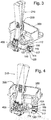
- the damping mechanism 100 is shown in the figures fitted in a shift selector assembly 200 of a motor vehicle transmission.
- the shift selector assembly 200 comprises a fixed part 300 and a movable part, that in this example corresponds to a shift lever 210.
- the shift lever 210 can be moved relative to the fixed part 300.
- the fixed part 300 is part of a shifter housing of the shift selector assembly 200 although it could be a part attached thereto.
- the shift lever 210 can be moved relative to the fixed part 300 in different directions biased onto a contoured surface 400.
- the contoured surface 400 is a bottom surface in a shifter housing where the shift lever 210 is movably mounted.
- the shift selector assembly 200 further includes a damping mechanism 100.
- the damping mechanism 100 is intended for absorbing impacts from the shift lever 210 as it is operated.
- Figure 1 shows by dotted lines different positions of the shift lever 210 during use for driving a vehicle transmission.
- the damping mechanism 100 comprises a damping element 110 configured in the form of a rotating damping disc 110.
- the damping disc 110 is made of a material such as rubber or similar material suitable for reducing or absorbing impacts, shocks, vibrations, etc. from the shift lever 210, for example when returning into a stable position in the shift selector assembly 200 after being operated for selecting a gearshift position.
- the damping disc 110 may however have other different shapes such as for example a cylinder, a ring, a sphere, or a portion of one of them having a lateral damping surface 115 suitable for absorbing impacts from the shift lever 210 as it is operated for driving a vehicle transmission.
- the damping mechanism 100 further comprises a support housing 120 configured with an interior suitable for receiving the damping disc 110.
- the damping disc 110 can be rotated around an axis of rotation 112. Also, the damping disc 110 can be moved along the interior of the support housing 120.
- the support housing 120 comprises first guides, grooves or channels 113, 114 formed along opposite, parallel upper and lower walls of the support housing 120.
- the axis of rotation 112, and thus the damping disc 110, is allowed to run along said first guides, grooves or channels 113, 114 in the support housing 120.
- the first guides, grooves or channels 113, 114 thus allow for the movement of the damping disc 110 relative to the fixed part 300 as it is impacted by the shift lever 210 during operation.
- the damping disc 110 is positioned in the shift selector assembly 200 in a location corresponding to a stable position of the shift lever 210, specifically in a location corresponding to the intersection of all the possible paths of the shift lever 210 in the shift selector assembly 200.
- the damping mechanism 100 is located in a lateral position in the shifter housing. When the damping element 110 is in a rest position, it is partly arranged in the corresponding location of the shift lever 210.
- the damping element 110 undergoes two basic movements as the shift lever 210 is operated during normal use: a frontal return movement in which most of the impact is absorbed by the resilient member 130, and a tangential return movement in which a tangential impact is most absorbed by the resilient member 130 combined with rotation of the dampening element 110 while allowing the movement of the shift lever 210. This tends to prevent or at least reduce friction on the shift lever 210 as it is driven in an opposite direction when leaving a stable position.
- a resilient member 130 is provided to act against the movement of the damping disc 110 relative to the fixed part 300.
- the resilient member comprises a wire spring 131.
- the wire spring 131 is inserted inside second guides, grooves or channels 116, 117 that are also formed in the support housing 120 to act on the damping disc 110.
- the support housing 120 could be part of the fixed part 300.
- the wire spring 131 may be a U-shaped wire spring intended to allow the axis of rotation 112 of damping element 110 to resiliently move in use.
- the resilient member 130 may comprise a single wire arranged at one end of the axis of rotation 112 of the damping element 110.
- the resilient member 130 may comprise two separate wires arranged at corresponding opposite ends of the axis of rotation 112 of the damping element 110.
- the wire spring 131 is suitable for causing the axis of rotation 112 of the damping element 110 to be displaced when in use.
- the resilient member 130 comprises a compression spring 132 that is fitted between the support housing 120 and the fixed part 300.
- the support housing 120 is allowed to resiliently move relative to the fixed part 300 by the impacts from the shift lever 210 against the damping disc 110.
- damping mechanism and shift selector assembly have been disclosed herein, it will be understood by those skilled in the art that other alternative examples and/or uses and obvious modifications and equivalents thereof are possible.
- resilient members have been shown comprising a wire spring or a compression spring, other types of resilient members may be used such as for example a viscoelastic or rubber element, etc. and even a combination of different resilient members.
- the damping element could be configured to be rotated but not to be resiliently displaced relative to the fixed part.
- the damping element may include at least one portion that is suitable to be deformed when absorbing impacts from the movable part such that displacement occurs via the resilient deformation said portion or portions of the damping element.
Landscapes
- Engineering & Computer Science (AREA)
- General Engineering & Computer Science (AREA)
- Mechanical Engineering (AREA)
- Gear-Shifting Mechanisms (AREA)
- Arrangement Or Mounting Of Control Devices For Change-Speed Gearing (AREA)
Priority Applications (3)
| Application Number | Priority Date | Filing Date | Title |
|---|---|---|---|
| EP17382584.5A EP3447340A1 (de) | 2017-08-25 | 2017-08-25 | Dämpfungsmechanismus für eine schaltwahlanordnung und schaltwahlanordnung mit diesem dämpfungsmechanismus |
| US16/111,617 US11287029B2 (en) | 2017-08-25 | 2018-08-24 | Damping mechanism for a shift selector assembly and a shift selector assembly comprising the damping mechanism |
| CN201810970820.1A CN109424736B (zh) | 2017-08-25 | 2018-08-24 | 用于挡位选择器组件的阻尼机构和挡位选择器组件 |
Applications Claiming Priority (1)
| Application Number | Priority Date | Filing Date | Title |
|---|---|---|---|
| EP17382584.5A EP3447340A1 (de) | 2017-08-25 | 2017-08-25 | Dämpfungsmechanismus für eine schaltwahlanordnung und schaltwahlanordnung mit diesem dämpfungsmechanismus |
Publications (1)
| Publication Number | Publication Date |
|---|---|
| EP3447340A1 true EP3447340A1 (de) | 2019-02-27 |
Family
ID=59713964
Family Applications (1)
| Application Number | Title | Priority Date | Filing Date |
|---|---|---|---|
| EP17382584.5A Withdrawn EP3447340A1 (de) | 2017-08-25 | 2017-08-25 | Dämpfungsmechanismus für eine schaltwahlanordnung und schaltwahlanordnung mit diesem dämpfungsmechanismus |
Country Status (3)
| Country | Link |
|---|---|
| US (1) | US11287029B2 (de) |
| EP (1) | EP3447340A1 (de) |
| CN (1) | CN109424736B (de) |
Families Citing this family (2)
| Publication number | Priority date | Publication date | Assignee | Title |
|---|---|---|---|---|
| KR20220028209A (ko) * | 2020-08-28 | 2022-03-08 | 현대자동차주식회사 | 차량용 다이얼 타입 변속 조작장치 |
| CN113643587B (zh) * | 2021-09-26 | 2023-03-10 | 重庆电子工程职业学院 | 电动教练车的换挡模拟机构 |
Citations (3)
| Publication number | Priority date | Publication date | Assignee | Title |
|---|---|---|---|---|
| WO2005037591A1 (de) * | 2003-10-11 | 2005-04-28 | Daimlerchrysler Ag | Wählhebel und verfahren zur herstellung eines wählhebels |
| JP2006182112A (ja) * | 2004-12-27 | 2006-07-13 | Tsuda Industries Co Ltd | 自動変速機用シフトレバー装置 |
| WO2015185280A1 (de) | 2014-06-06 | 2015-12-10 | Zf Friedrichshafen Ag | Vorrichtung zum einstellen einer bewegung eines bedienelements für ein automatikgetriebe eines fahrzeugs, verfahren zum herstellen derselben und schaltvorrichtung zum schalten eines automatikgetriebes eines fahrzeugs |
Family Cites Families (14)
| Publication number | Priority date | Publication date | Assignee | Title |
|---|---|---|---|---|
| US2172663A (en) * | 1939-09-12 | Extension gear lever | ||
| US4018099A (en) * | 1975-09-15 | 1977-04-19 | General Motors Corporation | Multispeed shift linkage control |
| DE3047117C2 (de) * | 1980-12-13 | 1983-11-24 | Zahnradfabrik Friedrichshafen Ag, 7990 Friedrichshafen | Rastvorrichtung |
| DE69611339T2 (de) * | 1995-10-24 | 2001-04-26 | Fuji Kiko Kk | Schalthebeleinrichtung für ein Automatikgetriebe |
| DE10006721A1 (de) * | 2000-02-15 | 2001-08-16 | Schaeffler Waelzlager Ohg | Schaltvorrichtung eines Wechselgetriebes mit Dämpfungselement und Schaltwegbegrenzung |
| SE518310C2 (sv) * | 2001-02-02 | 2002-09-24 | Kongsberg Automotive Ab | Centreringsanordning för långsträckta element och en omställningsanordning |
| JP4846534B2 (ja) * | 2006-11-17 | 2011-12-28 | アイシン・エーアイ株式会社 | シフトレバー装置 |
| DE102007058850A1 (de) * | 2007-12-05 | 2009-06-10 | Zf Friedrichshafen Ag | Betätigungseinrichtung mit Sperranordnung |
| US9829100B2 (en) * | 2015-05-07 | 2017-11-28 | GM Global Technology Operations LLC | Electronic shift system for an automated manual transmission |
| EP3128209B1 (de) * | 2015-08-05 | 2021-05-26 | Fico Triad, S.A. | Gangwählmechanismus für kraftfahrzeuggetriebe |
| US10174831B2 (en) * | 2015-10-02 | 2019-01-08 | Ford Global Technologies, Llc | Manual shifter reverse lockout mechanism with vibration isolation system |
| KR101644949B1 (ko) * | 2015-12-01 | 2016-08-03 | 지엠 글로벌 테크놀러지 오퍼레이션스 엘엘씨 | 자동변속기용 오조작 방지 장치 |
| DE102015225494A1 (de) * | 2015-12-16 | 2017-06-22 | Zf Friedrichshafen Ag | Schalthebel und Verfahren zum Herstellen eines Schalthebels |
| CN205654850U (zh) * | 2016-04-14 | 2016-10-19 | 北京汽车研究总院有限公司 | 变速器换挡杆总成及汽车 |
-
2017
- 2017-08-25 EP EP17382584.5A patent/EP3447340A1/de not_active Withdrawn
-
2018
- 2018-08-24 US US16/111,617 patent/US11287029B2/en active Active
- 2018-08-24 CN CN201810970820.1A patent/CN109424736B/zh active Active
Patent Citations (3)
| Publication number | Priority date | Publication date | Assignee | Title |
|---|---|---|---|---|
| WO2005037591A1 (de) * | 2003-10-11 | 2005-04-28 | Daimlerchrysler Ag | Wählhebel und verfahren zur herstellung eines wählhebels |
| JP2006182112A (ja) * | 2004-12-27 | 2006-07-13 | Tsuda Industries Co Ltd | 自動変速機用シフトレバー装置 |
| WO2015185280A1 (de) | 2014-06-06 | 2015-12-10 | Zf Friedrichshafen Ag | Vorrichtung zum einstellen einer bewegung eines bedienelements für ein automatikgetriebe eines fahrzeugs, verfahren zum herstellen derselben und schaltvorrichtung zum schalten eines automatikgetriebes eines fahrzeugs |
Also Published As
| Publication number | Publication date |
|---|---|
| CN109424736A (zh) | 2019-03-05 |
| CN109424736B (zh) | 2022-09-09 |
| US11287029B2 (en) | 2022-03-29 |
| US20190063592A1 (en) | 2019-02-28 |
Similar Documents
| Publication | Publication Date | Title |
|---|---|---|
| US7587958B2 (en) | De-Cel dampener method and apparatus | |
| US6196080B1 (en) | Shift lever unit for dual-mode automatic transmission | |
| EP3128209B1 (de) | Gangwählmechanismus für kraftfahrzeuggetriebe | |
| US4519268A (en) | Gear shift apparatus for manual transmission | |
| US11287029B2 (en) | Damping mechanism for a shift selector assembly and a shift selector assembly comprising the damping mechanism | |
| EP0459485A1 (de) | Schalteinrichtung eines automatischen Getriebes | |
| US4077275A (en) | Gearshift lever assembly | |
| JP2007182150A (ja) | アクセル装置のキックダウンスイッチ | |
| JP4563832B2 (ja) | シフトレバー装置 | |
| CN110886837B (zh) | 车辆用变速装置 | |
| CN112211996B (zh) | 车辆用换挡装置 | |
| JPS6349764Y2 (de) | ||
| KR102556356B1 (ko) | 차량용 변속 노브 조립체 | |
| JP2010006311A (ja) | シフトレバー装置 | |
| JPS624253B2 (de) | ||
| EP1520125B1 (de) | Schalthebelmechanismus | |
| JP4633385B2 (ja) | 変速機のチェンジ機構 | |
| JPS625379Y2 (de) | ||
| JPS6349763Y2 (de) | ||
| KR20070051012A (ko) | 자동변속 차량용 주차브레이크 잠금장치 | |
| JP2595886Y2 (ja) | 自動変速機の操作装置 | |
| JP2588383Y2 (ja) | 変速操作レバーの復帰装置 | |
| JPS5834505Y2 (ja) | 変速機の操作機構 | |
| JPS647063Y2 (de) | ||
| JP2020097304A (ja) | シフトレバー装置 |
Legal Events
| Date | Code | Title | Description |
|---|---|---|---|
| PUAI | Public reference made under article 153(3) epc to a published international application that has entered the european phase |
Free format text: ORIGINAL CODE: 0009012 |
|
| STAA | Information on the status of an ep patent application or granted ep patent |
Free format text: STATUS: THE APPLICATION HAS BEEN PUBLISHED |
|
| AK | Designated contracting states |
Kind code of ref document: A1 Designated state(s): AL AT BE BG CH CY CZ DE DK EE ES FI FR GB GR HR HU IE IS IT LI LT LU LV MC MK MT NL NO PL PT RO RS SE SI SK SM TR |
|
| AX | Request for extension of the european patent |
Extension state: BA ME |
|
| STAA | Information on the status of an ep patent application or granted ep patent |
Free format text: STATUS: REQUEST FOR EXAMINATION WAS MADE |
|
| 17P | Request for examination filed |
Effective date: 20190827 |
|
| RBV | Designated contracting states (corrected) |
Designated state(s): AL AT BE BG CH CY CZ DE DK EE ES FI FR GB GR HR HU IE IS IT LI LT LU LV MC MK MT NL NO PL PT RO RS SE SI SK SM TR |
|
| STAA | Information on the status of an ep patent application or granted ep patent |
Free format text: STATUS: EXAMINATION IS IN PROGRESS |
|
| 17Q | First examination report despatched |
Effective date: 20200511 |
|
| STAA | Information on the status of an ep patent application or granted ep patent |
Free format text: STATUS: EXAMINATION IS IN PROGRESS |
|
| STAA | Information on the status of an ep patent application or granted ep patent |
Free format text: STATUS: EXAMINATION IS IN PROGRESS |
|
| STAA | Information on the status of an ep patent application or granted ep patent |
Free format text: STATUS: THE APPLICATION IS DEEMED TO BE WITHDRAWN |
|
| 18D | Application deemed to be withdrawn |
Effective date: 20220323 |