EP3128209B1 - Gangwählmechanismus für kraftfahrzeuggetriebe - Google Patents
Gangwählmechanismus für kraftfahrzeuggetriebe Download PDFInfo
- Publication number
- EP3128209B1 EP3128209B1 EP15179896.4A EP15179896A EP3128209B1 EP 3128209 B1 EP3128209 B1 EP 3128209B1 EP 15179896 A EP15179896 A EP 15179896A EP 3128209 B1 EP3128209 B1 EP 3128209B1
- Authority
- EP
- European Patent Office
- Prior art keywords
- damper element
- plunger
- shift
- selector mechanism
- shift lever
- Prior art date
- Legal status (The legal status is an assumption and is not a legal conclusion. Google has not performed a legal analysis and makes no representation as to the accuracy of the status listed.)
- Active
Links
- 230000007246 mechanism Effects 0.000 title claims description 46
- 230000005540 biological transmission Effects 0.000 title claims description 11
- 230000014759 maintenance of location Effects 0.000 claims description 2
- 230000006835 compression Effects 0.000 description 12
- 238000007906 compression Methods 0.000 description 12
- 230000008878 coupling Effects 0.000 description 6
- 238000010168 coupling process Methods 0.000 description 6
- 238000005859 coupling reaction Methods 0.000 description 6
- 230000000717 retained effect Effects 0.000 description 5
- 230000035939 shock Effects 0.000 description 3
- 238000013016 damping Methods 0.000 description 2
- 238000006073 displacement reaction Methods 0.000 description 2
- 239000007787 solid Substances 0.000 description 2
- 238000006243 chemical reaction Methods 0.000 description 1
- 230000001419 dependent effect Effects 0.000 description 1
- 238000004519 manufacturing process Methods 0.000 description 1
- 239000000463 material Substances 0.000 description 1
- 230000004048 modification Effects 0.000 description 1
- 238000012986 modification Methods 0.000 description 1
Images


Classifications
-
- F—MECHANICAL ENGINEERING; LIGHTING; HEATING; WEAPONS; BLASTING
- F16—ENGINEERING ELEMENTS AND UNITS; GENERAL MEASURES FOR PRODUCING AND MAINTAINING EFFECTIVE FUNCTIONING OF MACHINES OR INSTALLATIONS; THERMAL INSULATION IN GENERAL
- F16H—GEARING
- F16H61/00—Control functions within control units of change-speed- or reversing-gearings for conveying rotary motion ; Control of exclusively fluid gearing, friction gearing, gearings with endless flexible members or other particular types of gearing
- F16H61/24—Providing feel, e.g. to enable selection
-
- F—MECHANICAL ENGINEERING; LIGHTING; HEATING; WEAPONS; BLASTING
- F16—ENGINEERING ELEMENTS AND UNITS; GENERAL MEASURES FOR PRODUCING AND MAINTAINING EFFECTIVE FUNCTIONING OF MACHINES OR INSTALLATIONS; THERMAL INSULATION IN GENERAL
- F16H—GEARING
- F16H59/00—Control inputs to control units of change-speed-, or reversing-gearings for conveying rotary motion
- F16H59/02—Selector apparatus
- F16H59/0208—Selector apparatus with means for suppression of vibrations or reduction of noise
-
- F—MECHANICAL ENGINEERING; LIGHTING; HEATING; WEAPONS; BLASTING
- F16—ENGINEERING ELEMENTS AND UNITS; GENERAL MEASURES FOR PRODUCING AND MAINTAINING EFFECTIVE FUNCTIONING OF MACHINES OR INSTALLATIONS; THERMAL INSULATION IN GENERAL
- F16H—GEARING
- F16H59/00—Control inputs to control units of change-speed-, or reversing-gearings for conveying rotary motion
- F16H59/02—Selector apparatus
- F16H2059/026—Details or special features of the selector casing or lever support
- F16H2059/0269—Ball joints or spherical bearings for supporting the lever
-
- F—MECHANICAL ENGINEERING; LIGHTING; HEATING; WEAPONS; BLASTING
- F16—ENGINEERING ELEMENTS AND UNITS; GENERAL MEASURES FOR PRODUCING AND MAINTAINING EFFECTIVE FUNCTIONING OF MACHINES OR INSTALLATIONS; THERMAL INSULATION IN GENERAL
- F16H—GEARING
- F16H59/00—Control inputs to control units of change-speed-, or reversing-gearings for conveying rotary motion
- F16H59/02—Selector apparatus
- F16H2059/0295—Selector apparatus with mechanisms to return lever to neutral or datum position, e.g. by return springs
-
- F—MECHANICAL ENGINEERING; LIGHTING; HEATING; WEAPONS; BLASTING
- F16—ENGINEERING ELEMENTS AND UNITS; GENERAL MEASURES FOR PRODUCING AND MAINTAINING EFFECTIVE FUNCTIONING OF MACHINES OR INSTALLATIONS; THERMAL INSULATION IN GENERAL
- F16H—GEARING
- F16H61/00—Control functions within control units of change-speed- or reversing-gearings for conveying rotary motion ; Control of exclusively fluid gearing, friction gearing, gearings with endless flexible members or other particular types of gearing
- F16H61/24—Providing feel, e.g. to enable selection
- F16H2061/243—Cams or detent arrays for guiding and providing feel
Definitions
- the present invention relates to shift mechanisms for controlling motor vehicle transmissions.
- Motor vehicle transmissions in particular motor vehicle automatic transmissions, comprise a shift mechanism that includes mutually movable parts such as for example a shift lever operable for selecting gearshift positions corresponding to different transmission gears, a movable spring biased plunger arranged to slide on a contoured surface as the shift lever is moved for selecting a gearshift position for giving the user a gearshift feel, etc.
- a shift mechanism that includes mutually movable parts such as for example a shift lever operable for selecting gearshift positions corresponding to different transmission gears, a movable spring biased plunger arranged to slide on a contoured surface as the shift lever is moved for selecting a gearshift position for giving the user a gearshift feel, etc.
- US7661334 teaches a gearshift mechanism comprising a gearshift lever movable to a gearshift housing that addresses the above issue.
- a plunger having a conical shape is provided movable to the gearshift lever.
- a spring urges the plunger with an axial spring force against a contoured surface that is attached to the gearshift housing.
- An elastically deformable ring is provided between the plunger and the gearshift lever such that, as the plunger passes over the contoured surface, the compression spring is compressed, urging the plunger through the elastically deformable ring such that the conical areas of the slotted ring and those of the plunger slide on one another and the ring expands until it comes into contact with the inner wall of the gearshift lever. This results in centring the plunger relative to the gearshift lever.
- EP2112408 discloses a shift-by-wire gearshift assembly with actuation means for varying the force imparted by biasing means to a gearshift lever in a way making the shifting operation to be allowed, harder to perform or even blocked from any gearshift lever position such that the user is suggested on the most suitable operation according to driving and other conditions.
- US2004226801 refers to a shifter with a powered pawl mechanism that selectively engages a shift gate.
- the shifter includes an electrically operated push button on the shift knob with sensors that determine the shift lever position for controlling a transmission.
- the present shift selector mechanism for motor vehicle transmissions comprises mutually movable first and second parts.
- the second part is movable relative to the first part.
- a spring member such as for example a compression spring, is provided.
- the spring member acts upon the second part such that the second part is biased onto a contoured surface.
- the first part is operated, e.g. for selecting a gearshift position, the second part slides on the contoured surface giving the user a gearshift feel.
- a damper element being a part of or attached to the second part is provided.
- the relative movement of the second part to the first part causes relative movement of the damper element to the first part without contacting the first part.
- relative movement between the first and second parts does not result in wearing down the damper element.
- the spring member acts upon the second part means herein that the spring member is arranged acting directly on the second part, without affecting other parts of the shift selector mechanism.
- the spring force of the spring member does not affect friction between gearshift mechanism moving parts so that friction between them does not vary during the relative movement between the first part and the second part.
- the hardness of the damper element may be selected based simply on desired properties of friction and damping.
- a damper element may be a flexible part, such as a pre-compressed member, for example an elastomeric member, also provided for absorbing forced vibrational energy, such as impacts or sudden shocks, to the first part.
- a damper element relates to any element, made for example of rubber or similar material, that is suitable for at least partially reducing or absorbing shock impulses, vibrations and impacts. For example, when the second part collides against the slopes of the contoured surface, forced vibrational energy is transferred from the second part to the first part.
- the arrangement of the damper element is such that the forced vibrational energy is at least partially reduced or absorbed from the second part to the first part. As a consequence, noise due to the collision of the second part against the slopes of the contoured surface is mitigated.
- the second part is a plunger arranged to at least partially slide within the first part.
- the plunger may for example comprise a plunger stem and a plunger head.
- the plunger head may be provided with a free end adapted to slide on the contoured surface as the first part is moved, e.g. for selecting a gearshift position giving the user the abovementioned gearshift feel.
- the plunger may also have a plunger stem.
- the plunger stem may be solid, with the spring member fitted outside the plunger stem, or it may be hollow, with the spring member fitted at least partially inside the plunger stem.
- the first part is a shift lever.
- the contoured surface may be a part of or may be attached to a shifter assembly housing.
- the first part may be a shifter assembly housing while the contoured surface may be a part of or may be attached to a shift lever.
- the damper element is a part of or is attached to the second part and such that relative movement of the second part to the first part causes relative movement of the damper element to the first part without contacting the first part.
- the second part is provided with a number of folding flanges adapted for surrounding the damper element to retain it in position, whereby in use the damper element remains trapped between the second part and the folding flanges preventing the damper element from directly contacting the shift lever.
- the first part may further comprise a bushing.
- the bushing may be a tubular part such as a sleeve or hollow shaft arranged for at least partially receiving the plunger therein such that the latter can slide thereto.
- the damper element may be arranged surrounding a bushing end portion between the element with the cavity and the bushing end portion. It may be preferred that the bushing end portion extends past the damper element such that the bushing end portion is located between the damper element and the contoured surface. As a result, the damper element is prevented from directly contacting the second part as the first part is moved.
- a damper element receiving portion may be formed in one of the first and second parts for receiving the damper element such that it is retained therein.
- the damper element may be configured so as to act upon the damper element receiving portion such that the damper element receiving portion is biased onto one of the first part and the second part. This configuration reduces free play between the first and second parts and further contributes to allowing selection of the hardness of the damper element based simply on desired properties of friction and damping.
- the damper element has at least one of a coupling protrusion or recess for engaging at least one corresponding coupling recess or protrusion formed at the bushing end portion.
- Other means for retaining the damper element in position are however not ruled out such as a number of flanges formed in the second part for surrounding the damper element or a number of flanges formed in the first part adapted to be surrounded by the damper element.
- the first part comprises a bushing
- the bushing may be slotted to define a number of flanges adapted to be surrounded by the damper element.
- flanges may be configured so as to provide a flexible retention of the damper element. As a result, the flanges cooperate with the damper element to reduce free plays between the first and second parts.
- the damper element may be arranged surrounding the second part in a groove provided in a pin head formed in the second part.
- the damper element is in turn surrounded by the folding flanges.
- a long travel for the plunger within the shift lever is no longer required for allowing a smooth gearshift feeling when the plunger passes over the contoured surface as the shift lever is moved when selecting a gearshift position.
- the shift selector mechanism 100 comprises a first part and a second part which are movable relative to each other.
- the first part is a shift lever 200.
- the reference numeral 200 could alternatively designate a bracket attached to the shift lever 200.
- the second part is a plunger 300 that is arranged to slide within the shift lever 200 when the shift lever 200 is operated.
- the plunger 300 comprises a plunger stem 310 and a plunger head 320.
- the plunger 300 has a first, free end 325 located at the plunger head 320 adapted to slide on a contoured surface 400.
- a contoured surface 400 is attached to a shifter assembly housing 800 that is shown in figure 7 .
- the contoured surface 400 is configured with protrusions, recesses and slopes to give the user a gearshift feel as the shift lever 200 is moved thereon for selecting a gearshift position for controlling the motor vehicle transmission.
- the plunger stem 310 is surrounded by or fits at least partially within a spring member in the form of a compression spring 500 for biasing the plunger 300 onto the contoured surface 400.
- the compression spring 500 is arranged to act directly upon the plunger 300 without acting on other parts of the mechanism 100. Specifically, a first end 510 of the compression spring 500 abuts the plunger head 320 at a surface 326, opposite to the abovementioned first, free end 325 of the plunger 300, such that the compression spring 500 acts upon the plunger head 320.
- the shift selector mechanism 100 of the examples also comprises a damper element 600.
- the damper element is a pre-compressed member, specifically an elastomeric O-ring 600 configured for suitably absorbing shock impulses, vibration, impacts, etc. acting upon the shift lever 200 for example when returning to a stable position after being operated for selecting a gearshift position.
- the O-ring 600 is also configured for at least partially reducing noise due to the collision of the plunger 300 against the contoured surface 400.
- Figures 1, 2 show a first example of the shift selector mechanism 100 and figures 3, 4 show a second example of the shift selector mechanism 100.
- the plunger 300 has a solid plunger stem 310 such that the compression spring 500 is arranged surrounding it.
- the O-ring 600 is attached to an inner surface of the shift lever 200.
- a tubular part or bushing 700 is provided attached to the shift lever 200. The bushing 700 is attached to the interior of the shift lever 200 and is sized to receive the plunger 300 such that it is allowed to freely slide therein.
- the bushing 700 has a first end portion 710 with a first opening 711 sized to receive the plunger head 320 such that the plunger head 320 is allowed to freely slide therein.
- the first end portion 710 is slotted such that a number of flanges are formed thereat.
- the damper element 600 is arranged surrounding the slotted end portion 710 of the bushing 700.
- the bushing 700 further has a second end portion 720, opposite to said first end portion 710, that is provided with a second opening 721 sized to receive the plunger stem 310 such that it is allowed to freely slide therein.
- the second end portion 720 also defines an abutment surface 722 upon which a second end 520 of the compression spring 500, opposite to the abovementioned first end 510 of the compression spring 500, abuts.
- the second end 520 of the compression spring 500 may be arranged to abut a surface of the shift lever 200.
- the slotted end portion 710 of the bushing 700 extends past the damper element 600 such that said bushing end portion 710 is located between the damper element 600 and the contoured surface 400.
- the damper element 600 is arranged surrounding the slotted end portion 710 of the bushing 700.
- the damper element 600 has a radial coupling protrusion 610 for engaging a corresponding coupling recess 328 formed at the slotted end portion 710 of the bushing 700.
- the damper element 600 may be provided with a coupling recess for engaging a corresponding coupling protrusion formed at the slotted end portion 710 of the bushing 700.
- the damper element 600 is retained in the shift lever 200 and prevented from directly contacting the plunger 300 when in use.
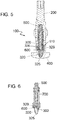
- Figures 5, 6 show a third example of the shift selector mechanism 100 and figures 7-10 show a fourth example of the shift selector mechanism 100.
- the plunger 300 has a hollow plunger stem 310 such that the compression spring 500 is arranged partially inserted therein.
- the O-ring 600 is attached to the plunger 300. Specifically, in said examples the O-ring 600 is attached to an outer surface of the plunger 300 in the vicinity of the plunger head 320.
- the plunger 300 includes a receiving portion 329 that is adapted to receive the damper element 600 retained in position therein.
- the receiving portion 329 may be slotted so as to define a number of flanges formed thereat.
- the damper element 600 remains retained between the plunger receiving portion 329 and the plunger first end 325 prevented from directly contacting the shift lever 200 when in use.
- no bushing is required.
- the plunger 300 is provided with a number of plunger folding flanges 327 which are shown in figures 8-10 .
- the folding flanges 327 serve the purpose of preventing the damper element 600 from directly contacting the shift lever 200 when in use.
- the damper element 600 is arranged surrounding the plunger 300 in a groove 328 provided in the vicinity of the pin head 320 and is in turn surrounded by the folding flanges 327. In use, the damper element 600 remains trapped between the plunger first end 325 and the folding flanges 327, retained in position in the plunger 300 and, thus, prevented from directly contacting the shift lever 200 when in use.
- no bushing is required.
- Figure 11 shows a fifth example of the shift selector mechanism 100.
- the first part is the shifter assembly housing 800 and the contoured surface 400 is attached to the shift lever 200.
- the second part i.e. the plunger 300, is adapted to slide on the contoured surface 400 and arranged to slide within the shifter assembly housing 800.
- the plunger head 320 slides on the contoured surface 400 following the protrusions, recesses and slopes and causes the plunger 300 to slide within the shifter assembly housing 800.
- the plunger head 320 When no gearshift operations are performed, the plunger head 320 remains in a stable gearshift position, usually referred to as idle or home gearshift position, that is defined into which the shift lever 200 automatically returns after it has been moved for selecting a desired gearshift position.
- idle position corresponds to a recess of the contoured surface 400.
- Displacement of the shift lever 200 causes the plunger head 320 to abandon the idle position and start following a slope of the contoured surface 400. Such displacement generates a reaction force in the plunger head 320 with both a normal and a tangential component.
- the normal component is transmitted to the compression spring 500, which urges the plunger head 320 to remain in contact with the contoured surface 400.
- the tangential component is transmitted to the damper element 600, which deforms accordingly to absorb it. As a result, free play between the plunger head 320 and the shift lever 200 is eliminated by the deformation of the damper element 600.
- deformation of the damper element 600 causes deformation of the flanges formed at the slotted end portion 710 of the bushing 700 so as to remain in contact with the plunger 300. In other words, the flanges are urged against the plunger 300 by the damper element 600.
- deformation of the damper element 600 causes deformation of the flanges formed at the plunger 300 so as to remain in contact with the shift lever 200. In other words, the flanges are urged against the shift lever 200 by the damper element 600.
Claims (7)
- Ein Schaltwahlmechanismus (100) für Kraftfahrzeuggetriebe, umfassend:- einen ersten Teil (200);- einen zweiten Teil (300), der relativ zum ersten Teil (200) beweglich ist;- ein Federelement (500), das auf den zweiten Teil (300) so einwirkt, dass der zweite Teil (300) auf eine konturierte Oberfläche (400) vorgespannt ist; und- ein Dämpferelement (600) zum Dämpfen von Stößen auf den ersten Teil (200), wobei das Dämpferelement (600) ein Teil des zweiten Teils (300) ist oder an diesem angebracht ist, und so dass eine Relativbewegung des zweiten Teils (300) zum ersten Teil (200) eine Relativbewegung des Dämpferelements (600) zum ersten Teil (200) verursacht, ohne den ersten Teil (200) zu berühren,wobei der zweite Teil ein Kolben (300) ist, der so angeordnet ist, dass er zumindest teilweise innerhalb des ersten Teils (200) geschoben wird und wobei der erste Teil (200) ein Schalthebel ist,
dadurch gekennzeichnet, dass der zweite Teil (300) mit einer Vielzahl von Faltflanschen (327) versehen ist, die angepasst sind, um das Dämpferelement (600) zu umgeben, um es im Platz zu halten, wobei das Dämpferelement (600) zwischen dem zweiten Teil (300) und den Faltflanschen (327) eingeschlossen bleibt, wodurch ein unmittelbarer Kontakt des Dämpferelements (600) mit dem Schalthebel (200) vermieden wird. - Der Mechanismus (100) nach Anspruch 1, wobei der zweite Teil (300) einen Dämpferelement-Aufnahmeabschnitt (329) umfasst, der dazu ausgelegt ist, das Dämpferelement (600) aufzunehmen und es in Position zu halten.
- Der Mechanismus (100) nach Anspruch 2, wobei das Dämpferelement (600) konfiguriert ist, um auf den Dämpferelement-Aufnahmeabschnitt (329) derart zu wirken, dass der Dämpferelement-Aufnahmeabschnitt (329) auf den ersten Teil (200) vorgespannt ist.
- Der Mechanismus (100) nach einem der vorhergehenden Ansprüche, wobei das Dämpferelement (600) ein vorkomprimiertes Element oder ein elastomeres Element ist.
- Der Mechanismus (100) nach einem der vorhergehenden Ansprüche, wobei die konturierte Oberfläche (400) ein Teil eines Schaltanordnungsgehäuses (800) ist oder an diesem angebracht ist.
- Der Mechanismus (100) nach einem der vorhergehenden Ansprüche, wobei die Faltflansche (327) konfiguriert sind, um eine flexible Halterung des Dämpferelements (600) zu bieten.
- Der Mechanismus (100) nach einem der vorhergehenden Ansprüche, wobei das Dämpferelement (600) so angeordnet ist, dass es den zweiten Teil (300) in einem Spalt (328) umgibt, der in einem im zweiten Teil (300) gebildeten Zapfenkopf (320) vorhanden ist, wobei das Dämpferelement (600) wiederum von den Faltflanschen (327) umgeben ist.
Priority Applications (2)
| Application Number | Priority Date | Filing Date | Title |
|---|---|---|---|
| EP15179896.4A EP3128209B1 (de) | 2015-08-05 | 2015-08-05 | Gangwählmechanismus für kraftfahrzeuggetriebe |
| US15/222,809 US10088042B2 (en) | 2015-08-05 | 2016-07-28 | Shift selector mechanism for motor vehicle transmissions |
Applications Claiming Priority (1)
| Application Number | Priority Date | Filing Date | Title |
|---|---|---|---|
| EP15179896.4A EP3128209B1 (de) | 2015-08-05 | 2015-08-05 | Gangwählmechanismus für kraftfahrzeuggetriebe |
Publications (2)
| Publication Number | Publication Date |
|---|---|
| EP3128209A1 EP3128209A1 (de) | 2017-02-08 |
| EP3128209B1 true EP3128209B1 (de) | 2021-05-26 |
Family
ID=53879343
Family Applications (1)
| Application Number | Title | Priority Date | Filing Date |
|---|---|---|---|
| EP15179896.4A Active EP3128209B1 (de) | 2015-08-05 | 2015-08-05 | Gangwählmechanismus für kraftfahrzeuggetriebe |
Country Status (2)
| Country | Link |
|---|---|
| US (1) | US10088042B2 (de) |
| EP (1) | EP3128209B1 (de) |
Families Citing this family (6)
| Publication number | Priority date | Publication date | Assignee | Title |
|---|---|---|---|---|
| KR102324753B1 (ko) * | 2017-03-16 | 2021-11-10 | 현대자동차주식회사 | 변속조작기구의 조작감 부여장치 |
| EP3447340A1 (de) * | 2017-08-25 | 2019-02-27 | Fico Triad, S.A. | Dämpfungsmechanismus für eine schaltwahlanordnung und schaltwahlanordnung mit diesem dämpfungsmechanismus |
| CN111550550B (zh) * | 2020-03-31 | 2023-01-06 | 武汉路特斯汽车有限公司 | 一种降噪电子换档器及汽车 |
| CN112937294B (zh) * | 2021-03-31 | 2022-09-06 | 重庆长安汽车股份有限公司 | 一种换挡底座总成 |
| US11781644B2 (en) * | 2021-07-23 | 2023-10-10 | Ghsp, Inc. | Selector assembly having an internal ball joint and detent mechanism |
| JP2023184324A (ja) * | 2022-06-17 | 2023-12-28 | 株式会社東海理化電機製作所 | シフト装置 |
Citations (1)
| Publication number | Priority date | Publication date | Assignee | Title |
|---|---|---|---|---|
| EP0255418A1 (de) * | 1986-06-30 | 1988-02-03 | Jaeger | Rastvorrichtung, insbesondere für Schalter für Kraftfahrzeuge |
Family Cites Families (23)
| Publication number | Priority date | Publication date | Assignee | Title |
|---|---|---|---|---|
| US4768393A (en) * | 1987-03-30 | 1988-09-06 | Dana Corporation | Vibration dampening coupling for compound shift lever |
| DE4313564C1 (de) * | 1993-04-26 | 1994-06-23 | Daimler Benz Ag | Schaltvorrichtung für ein Zahnräderwechselgetriebe eines Kraftfahrzeuges |
| US6026698A (en) * | 1996-08-13 | 2000-02-22 | Weston; Bevan | Transmission and shift mechanism |
| SE518310C2 (sv) | 2001-02-02 | 2002-09-24 | Kongsberg Automotive Ab | Centreringsanordning för långsträckta element och en omställningsanordning |
| DE10148554C1 (de) * | 2001-10-01 | 2003-03-13 | Kostal Leopold Gmbh & Co Kg | Schalteinrichtung sowie Anordnung bestehend aus einem Rastbolzengehäuse und einem Rastbolzen |
| DE10220437A1 (de) * | 2002-05-08 | 2003-11-20 | Valeo Schalter & Sensoren Gmbh | Schalter, insbesondere Lenkstockschalter für Fahrzeug |
| US20040226801A1 (en) * | 2003-05-15 | 2004-11-18 | De Jonge Robert A. | Vehicle shifter |
| DE10344287B4 (de) | 2003-09-23 | 2005-12-08 | Zf Friedrichshafen Ag | Rastiervorrichtung |
| DE10359067A1 (de) * | 2003-12-16 | 2005-07-21 | Ina-Schaeffler Kg | Arretierelement |
| DE102005014303B4 (de) * | 2005-03-30 | 2008-12-24 | Hofer-Pdc Gmbh | Rastiereinhiet für ein Schaltwelle |
| DE102005034864B4 (de) * | 2005-07-26 | 2008-11-27 | Knorr-Bremse Systeme für Nutzfahrzeuge GmbH | Stellvorrichtung für ein Getriebe |
| US7779715B2 (en) * | 2006-07-05 | 2010-08-24 | Grand Haven Stamped Products, A Division Of Jsj Corporation | Shifter with actuator incorporating magnetic unlock mechanism |
| KR100800126B1 (ko) * | 2006-08-17 | 2008-01-31 | 에스엘 주식회사 | 전자식 변속 레버 |
| US7467569B2 (en) | 2007-01-04 | 2008-12-23 | Dura Global Technologies, Inc. | Detent plunger for automatic transmission shifter |
| EP2112408B1 (de) * | 2008-04-23 | 2011-12-21 | Fico Triad S.A. | Shift-by-Wire-Schaltanordnung |
| EP2184517B1 (de) * | 2008-11-11 | 2015-07-29 | Fico Triad S.A. | Shift-by-Wire-Schaltvorrichtung |
| DE102009058719B4 (de) * | 2009-12-17 | 2017-12-07 | Valeo Schalter Und Sensoren Gmbh | Anordnung mit einem Raststößel |
| DE102010034280A1 (de) * | 2010-08-13 | 2012-02-16 | Schaeffler Technologies Gmbh & Co. Kg | Arretierung mit Erfassung von Rastpositionen |
| US9664276B2 (en) * | 2013-10-24 | 2017-05-30 | Fca Us Llc | Transmission electronic shifter with adjustable damped friction clutch |
| DE102014107080A1 (de) * | 2014-05-20 | 2015-11-26 | Ecs Engineered Control Systems Ag | Haltevorrichtung sowie Stift zur Anordnung in einer solchen Haltevorrichtung |
| DE102014213599A1 (de) * | 2014-07-14 | 2016-01-14 | Schaeffler Technologies AG & Co. KG | Arretiervorrichtung für ein Fahrzeuggetriebe sowie Fahrzeuggetriebe mit der Arretiervorrichtung |
| JP6281951B2 (ja) * | 2014-10-09 | 2018-02-21 | アルプス電気株式会社 | 車両用操作装置 |
| DE102015003553A1 (de) * | 2015-03-19 | 2016-09-22 | Leopold Kostal Gmbh & Co. Kg | Schalter, insbesondere Lenkstockschalter für ein Kraftfahrzeug |
-
2015
- 2015-08-05 EP EP15179896.4A patent/EP3128209B1/de active Active
-
2016
- 2016-07-28 US US15/222,809 patent/US10088042B2/en active Active
Patent Citations (1)
| Publication number | Priority date | Publication date | Assignee | Title |
|---|---|---|---|---|
| EP0255418A1 (de) * | 1986-06-30 | 1988-02-03 | Jaeger | Rastvorrichtung, insbesondere für Schalter für Kraftfahrzeuge |
Also Published As
| Publication number | Publication date |
|---|---|
| US10088042B2 (en) | 2018-10-02 |
| EP3128209A1 (de) | 2017-02-08 |
| US20170037962A1 (en) | 2017-02-09 |
Similar Documents
| Publication | Publication Date | Title |
|---|---|---|
| EP3128209B1 (de) | Gangwählmechanismus für kraftfahrzeuggetriebe | |
| KR101384009B1 (ko) | 작동 장치 | |
| US6196080B1 (en) | Shift lever unit for dual-mode automatic transmission | |
| US20150219207A1 (en) | Transmission shift selector assembly | |
| US11287029B2 (en) | Damping mechanism for a shift selector assembly and a shift selector assembly comprising the damping mechanism | |
| JP6448312B2 (ja) | シフトレバーユニット | |
| US8312790B2 (en) | One touch combination structure of knob for automatic transmission | |
| US9086129B2 (en) | Shift lever assembly with axially offset noise and vibration damper | |
| EP3617558B1 (de) | Schalthebelvorrichtung | |
| KR102522916B1 (ko) | 차량용 변속 장치 | |
| JP6890892B2 (ja) | 自動変速機のシフトロック機構 | |
| JPS6349764Y2 (de) | ||
| JP2019026156A (ja) | シフトレバーユニット | |
| JP6501603B2 (ja) | シフトレバーユニット | |
| JP6423248B2 (ja) | シフトレバーユニット | |
| KR102184262B1 (ko) | Amt 변속기용 전자기 구동장치 및 이를 이용한 변속방법 | |
| JP4633385B2 (ja) | 変速機のチェンジ機構 | |
| JP4593167B2 (ja) | リバースミスシフト防止構造 | |
| KR101847276B1 (ko) | 수동변속기의 쉬프트 레일 | |
| JP5178563B2 (ja) | 車両用シフトレバー装置 | |
| JP2595886Y2 (ja) | 自動変速機の操作装置 | |
| JPS6349763Y2 (de) | ||
| KR930005432Y1 (ko) | 자동변속기의 조작장치 | |
| JPS6142170Y2 (de) | ||
| CN110871682A (zh) | 换挡杆装置 |
Legal Events
| Date | Code | Title | Description |
|---|---|---|---|
| PUAI | Public reference made under article 153(3) epc to a published international application that has entered the european phase |
Free format text: ORIGINAL CODE: 0009012 |
|
| STAA | Information on the status of an ep patent application or granted ep patent |
Free format text: STATUS: THE APPLICATION HAS BEEN PUBLISHED |
|
| AK | Designated contracting states |
Kind code of ref document: A1 Designated state(s): AL AT BE BG CH CY CZ DE DK EE ES FI FR GB GR HR HU IE IS IT LI LT LU LV MC MK MT NL NO PL PT RO RS SE SI SK SM TR |
|
| AX | Request for extension of the european patent |
Extension state: BA ME |
|
| STAA | Information on the status of an ep patent application or granted ep patent |
Free format text: STATUS: REQUEST FOR EXAMINATION WAS MADE |
|
| 17P | Request for examination filed |
Effective date: 20170808 |
|
| RBV | Designated contracting states (corrected) |
Designated state(s): AL AT BE BG CH CY CZ DE DK EE ES FI FR GB GR HR HU IE IS IT LI LT LU LV MC MK MT NL NO PL PT RO RS SE SI SK SM TR |
|
| STAA | Information on the status of an ep patent application or granted ep patent |
Free format text: STATUS: EXAMINATION IS IN PROGRESS |
|
| 17Q | First examination report despatched |
Effective date: 20190802 |
|
| GRAP | Despatch of communication of intention to grant a patent |
Free format text: ORIGINAL CODE: EPIDOSNIGR1 |
|
| STAA | Information on the status of an ep patent application or granted ep patent |
Free format text: STATUS: GRANT OF PATENT IS INTENDED |
|
| INTG | Intention to grant announced |
Effective date: 20200320 |
|
| GRAJ | Information related to disapproval of communication of intention to grant by the applicant or resumption of examination proceedings by the epo deleted |
Free format text: ORIGINAL CODE: EPIDOSDIGR1 |
|
| STAA | Information on the status of an ep patent application or granted ep patent |
Free format text: STATUS: EXAMINATION IS IN PROGRESS |
|
| INTC | Intention to grant announced (deleted) | ||
| GRAP | Despatch of communication of intention to grant a patent |
Free format text: ORIGINAL CODE: EPIDOSNIGR1 |
|
| STAA | Information on the status of an ep patent application or granted ep patent |
Free format text: STATUS: GRANT OF PATENT IS INTENDED |
|
| INTG | Intention to grant announced |
Effective date: 20201217 |
|
| GRAS | Grant fee paid |
Free format text: ORIGINAL CODE: EPIDOSNIGR3 |
|
| GRAA | (expected) grant |
Free format text: ORIGINAL CODE: 0009210 |
|
| STAA | Information on the status of an ep patent application or granted ep patent |
Free format text: STATUS: THE PATENT HAS BEEN GRANTED |
|
| AK | Designated contracting states |
Kind code of ref document: B1 Designated state(s): AL AT BE BG CH CY CZ DE DK EE ES FI FR GB GR HR HU IE IS IT LI LT LU LV MC MK MT NL NO PL PT RO RS SE SI SK SM TR |
|
| REG | Reference to a national code |
Ref country code: GB Ref legal event code: FG4D |
|
| REG | Reference to a national code |
Ref country code: CH Ref legal event code: EP |
|
| REG | Reference to a national code |
Ref country code: DE Ref legal event code: R096 Ref document number: 602015069646 Country of ref document: DE |
|
| REG | Reference to a national code |
Ref country code: AT Ref legal event code: REF Ref document number: 1396544 Country of ref document: AT Kind code of ref document: T Effective date: 20210615 |
|
| REG | Reference to a national code |
Ref country code: IE Ref legal event code: FG4D |
|
| REG | Reference to a national code |
Ref country code: LT Ref legal event code: MG9D |
|
| REG | Reference to a national code |
Ref country code: AT Ref legal event code: MK05 Ref document number: 1396544 Country of ref document: AT Kind code of ref document: T Effective date: 20210526 |
|
| PG25 | Lapsed in a contracting state [announced via postgrant information from national office to epo] |
Ref country code: LT Free format text: LAPSE BECAUSE OF FAILURE TO SUBMIT A TRANSLATION OF THE DESCRIPTION OR TO PAY THE FEE WITHIN THE PRESCRIBED TIME-LIMIT Effective date: 20210526 Ref country code: FI Free format text: LAPSE BECAUSE OF FAILURE TO SUBMIT A TRANSLATION OF THE DESCRIPTION OR TO PAY THE FEE WITHIN THE PRESCRIBED TIME-LIMIT Effective date: 20210526 Ref country code: AT Free format text: LAPSE BECAUSE OF FAILURE TO SUBMIT A TRANSLATION OF THE DESCRIPTION OR TO PAY THE FEE WITHIN THE PRESCRIBED TIME-LIMIT Effective date: 20210526 Ref country code: BG Free format text: LAPSE BECAUSE OF FAILURE TO SUBMIT A TRANSLATION OF THE DESCRIPTION OR TO PAY THE FEE WITHIN THE PRESCRIBED TIME-LIMIT Effective date: 20210826 Ref country code: HR Free format text: LAPSE BECAUSE OF FAILURE TO SUBMIT A TRANSLATION OF THE DESCRIPTION OR TO PAY THE FEE WITHIN THE PRESCRIBED TIME-LIMIT Effective date: 20210526 |
|
| REG | Reference to a national code |
Ref country code: NL Ref legal event code: MP Effective date: 20210526 |
|
| PG25 | Lapsed in a contracting state [announced via postgrant information from national office to epo] |
Ref country code: PT Free format text: LAPSE BECAUSE OF FAILURE TO SUBMIT A TRANSLATION OF THE DESCRIPTION OR TO PAY THE FEE WITHIN THE PRESCRIBED TIME-LIMIT Effective date: 20210927 Ref country code: PL Free format text: LAPSE BECAUSE OF FAILURE TO SUBMIT A TRANSLATION OF THE DESCRIPTION OR TO PAY THE FEE WITHIN THE PRESCRIBED TIME-LIMIT Effective date: 20210526 Ref country code: NO Free format text: LAPSE BECAUSE OF FAILURE TO SUBMIT A TRANSLATION OF THE DESCRIPTION OR TO PAY THE FEE WITHIN THE PRESCRIBED TIME-LIMIT Effective date: 20210826 Ref country code: RS Free format text: LAPSE BECAUSE OF FAILURE TO SUBMIT A TRANSLATION OF THE DESCRIPTION OR TO PAY THE FEE WITHIN THE PRESCRIBED TIME-LIMIT Effective date: 20210526 Ref country code: SE Free format text: LAPSE BECAUSE OF FAILURE TO SUBMIT A TRANSLATION OF THE DESCRIPTION OR TO PAY THE FEE WITHIN THE PRESCRIBED TIME-LIMIT Effective date: 20210526 Ref country code: LV Free format text: LAPSE BECAUSE OF FAILURE TO SUBMIT A TRANSLATION OF THE DESCRIPTION OR TO PAY THE FEE WITHIN THE PRESCRIBED TIME-LIMIT Effective date: 20210526 Ref country code: IS Free format text: LAPSE BECAUSE OF FAILURE TO SUBMIT A TRANSLATION OF THE DESCRIPTION OR TO PAY THE FEE WITHIN THE PRESCRIBED TIME-LIMIT Effective date: 20210926 Ref country code: GR Free format text: LAPSE BECAUSE OF FAILURE TO SUBMIT A TRANSLATION OF THE DESCRIPTION OR TO PAY THE FEE WITHIN THE PRESCRIBED TIME-LIMIT Effective date: 20210827 |
|
| PG25 | Lapsed in a contracting state [announced via postgrant information from national office to epo] |
Ref country code: NL Free format text: LAPSE BECAUSE OF FAILURE TO SUBMIT A TRANSLATION OF THE DESCRIPTION OR TO PAY THE FEE WITHIN THE PRESCRIBED TIME-LIMIT Effective date: 20210526 |
|
| PG25 | Lapsed in a contracting state [announced via postgrant information from national office to epo] |
Ref country code: SM Free format text: LAPSE BECAUSE OF FAILURE TO SUBMIT A TRANSLATION OF THE DESCRIPTION OR TO PAY THE FEE WITHIN THE PRESCRIBED TIME-LIMIT Effective date: 20210526 Ref country code: SK Free format text: LAPSE BECAUSE OF FAILURE TO SUBMIT A TRANSLATION OF THE DESCRIPTION OR TO PAY THE FEE WITHIN THE PRESCRIBED TIME-LIMIT Effective date: 20210526 Ref country code: DK Free format text: LAPSE BECAUSE OF FAILURE TO SUBMIT A TRANSLATION OF THE DESCRIPTION OR TO PAY THE FEE WITHIN THE PRESCRIBED TIME-LIMIT Effective date: 20210526 Ref country code: CZ Free format text: LAPSE BECAUSE OF FAILURE TO SUBMIT A TRANSLATION OF THE DESCRIPTION OR TO PAY THE FEE WITHIN THE PRESCRIBED TIME-LIMIT Effective date: 20210526 Ref country code: EE Free format text: LAPSE BECAUSE OF FAILURE TO SUBMIT A TRANSLATION OF THE DESCRIPTION OR TO PAY THE FEE WITHIN THE PRESCRIBED TIME-LIMIT Effective date: 20210526 Ref country code: RO Free format text: LAPSE BECAUSE OF FAILURE TO SUBMIT A TRANSLATION OF THE DESCRIPTION OR TO PAY THE FEE WITHIN THE PRESCRIBED TIME-LIMIT Effective date: 20210526 Ref country code: ES Free format text: LAPSE BECAUSE OF FAILURE TO SUBMIT A TRANSLATION OF THE DESCRIPTION OR TO PAY THE FEE WITHIN THE PRESCRIBED TIME-LIMIT Effective date: 20210526 |
|
| REG | Reference to a national code |
Ref country code: DE Ref legal event code: R097 Ref document number: 602015069646 Country of ref document: DE |
|
| REG | Reference to a national code |
Ref country code: CH Ref legal event code: PL |
|
| PLBE | No opposition filed within time limit |
Free format text: ORIGINAL CODE: 0009261 |
|
| STAA | Information on the status of an ep patent application or granted ep patent |
Free format text: STATUS: NO OPPOSITION FILED WITHIN TIME LIMIT |
|
| PG25 | Lapsed in a contracting state [announced via postgrant information from national office to epo] |
Ref country code: MC Free format text: LAPSE BECAUSE OF FAILURE TO SUBMIT A TRANSLATION OF THE DESCRIPTION OR TO PAY THE FEE WITHIN THE PRESCRIBED TIME-LIMIT Effective date: 20210526 |
|
| REG | Reference to a national code |
Ref country code: BE Ref legal event code: MM Effective date: 20210831 |
|
| GBPC | Gb: european patent ceased through non-payment of renewal fee |
Effective date: 20210826 |
|
| PG25 | Lapsed in a contracting state [announced via postgrant information from national office to epo] |
Ref country code: LI Free format text: LAPSE BECAUSE OF NON-PAYMENT OF DUE FEES Effective date: 20210831 Ref country code: CH Free format text: LAPSE BECAUSE OF NON-PAYMENT OF DUE FEES Effective date: 20210831 |
|
| 26N | No opposition filed |
Effective date: 20220301 |
|
| PG25 | Lapsed in a contracting state [announced via postgrant information from national office to epo] |
Ref country code: IS Free format text: LAPSE BECAUSE OF FAILURE TO SUBMIT A TRANSLATION OF THE DESCRIPTION OR TO PAY THE FEE WITHIN THE PRESCRIBED TIME-LIMIT Effective date: 20210926 Ref country code: LU Free format text: LAPSE BECAUSE OF NON-PAYMENT OF DUE FEES Effective date: 20210805 Ref country code: AL Free format text: LAPSE BECAUSE OF FAILURE TO SUBMIT A TRANSLATION OF THE DESCRIPTION OR TO PAY THE FEE WITHIN THE PRESCRIBED TIME-LIMIT Effective date: 20210526 |
|
| PG25 | Lapsed in a contracting state [announced via postgrant information from national office to epo] |
Ref country code: IT Free format text: LAPSE BECAUSE OF FAILURE TO SUBMIT A TRANSLATION OF THE DESCRIPTION OR TO PAY THE FEE WITHIN THE PRESCRIBED TIME-LIMIT Effective date: 20210526 Ref country code: IE Free format text: LAPSE BECAUSE OF NON-PAYMENT OF DUE FEES Effective date: 20210805 Ref country code: GB Free format text: LAPSE BECAUSE OF NON-PAYMENT OF DUE FEES Effective date: 20210826 Ref country code: FR Free format text: LAPSE BECAUSE OF NON-PAYMENT OF DUE FEES Effective date: 20210831 Ref country code: BE Free format text: LAPSE BECAUSE OF NON-PAYMENT OF DUE FEES Effective date: 20210831 |
|
| PG25 | Lapsed in a contracting state [announced via postgrant information from national office to epo] |
Ref country code: HU Free format text: LAPSE BECAUSE OF FAILURE TO SUBMIT A TRANSLATION OF THE DESCRIPTION OR TO PAY THE FEE WITHIN THE PRESCRIBED TIME-LIMIT; INVALID AB INITIO Effective date: 20150805 |
|
| PG25 | Lapsed in a contracting state [announced via postgrant information from national office to epo] |
Ref country code: CY Free format text: LAPSE BECAUSE OF FAILURE TO SUBMIT A TRANSLATION OF THE DESCRIPTION OR TO PAY THE FEE WITHIN THE PRESCRIBED TIME-LIMIT Effective date: 20210526 |
|
| PGFP | Annual fee paid to national office [announced via postgrant information from national office to epo] |
Ref country code: DE Payment date: 20230829 Year of fee payment: 9 |