EP3441271A1 - Reinigungssystem einer fahrzeug-glasoberfläche - Google Patents
Reinigungssystem einer fahrzeug-glasoberfläche Download PDFInfo
- Publication number
- EP3441271A1 EP3441271A1 EP18185645.1A EP18185645A EP3441271A1 EP 3441271 A1 EP3441271 A1 EP 3441271A1 EP 18185645 A EP18185645 A EP 18185645A EP 3441271 A1 EP3441271 A1 EP 3441271A1
- Authority
- EP
- European Patent Office
- Prior art keywords
- hydraulic
- distribution bus
- bus
- cleaning
- hydraulic distribution
- Prior art date
- Legal status (The legal status is an assumption and is not a legal conclusion. Google has not performed a legal analysis and makes no representation as to the accuracy of the status listed.)
- Granted
Links
Images
Classifications
-
- B—PERFORMING OPERATIONS; TRANSPORTING
- B60—VEHICLES IN GENERAL
- B60S—SERVICING, CLEANING, REPAIRING, SUPPORTING, LIFTING, OR MANOEUVRING OF VEHICLES, NOT OTHERWISE PROVIDED FOR
- B60S1/00—Cleaning of vehicles
- B60S1/02—Cleaning windscreens, windows or optical devices
- B60S1/46—Cleaning windscreens, windows or optical devices using liquid; Windscreen washers
- B60S1/48—Liquid supply therefor
- B60S1/481—Liquid supply therefor the operation of at least part of the liquid supply being controlled by electric means
-
- B—PERFORMING OPERATIONS; TRANSPORTING
- B08—CLEANING
- B08B—CLEANING IN GENERAL; PREVENTION OF FOULING IN GENERAL
- B08B3/00—Cleaning by methods involving the use or presence of liquid or steam
- B08B3/02—Cleaning by the force of jets or sprays
-
- B—PERFORMING OPERATIONS; TRANSPORTING
- B60—VEHICLES IN GENERAL
- B60S—SERVICING, CLEANING, REPAIRING, SUPPORTING, LIFTING, OR MANOEUVRING OF VEHICLES, NOT OTHERWISE PROVIDED FOR
- B60S1/00—Cleaning of vehicles
- B60S1/02—Cleaning windscreens, windows or optical devices
- B60S1/04—Wipers or the like, e.g. scrapers
- B60S1/06—Wipers or the like, e.g. scrapers characterised by the drive
- B60S1/08—Wipers or the like, e.g. scrapers characterised by the drive electrically driven
- B60S1/0818—Wipers or the like, e.g. scrapers characterised by the drive electrically driven including control systems responsive to external conditions, e.g. by detection of moisture, dirt or the like
- B60S1/0822—Wipers or the like, e.g. scrapers characterised by the drive electrically driven including control systems responsive to external conditions, e.g. by detection of moisture, dirt or the like characterized by the arrangement or type of detection means
- B60S1/0833—Optical rain sensor
- B60S1/0844—Optical rain sensor including a camera
- B60S1/0848—Cleaning devices for cameras on vehicle
-
- B—PERFORMING OPERATIONS; TRANSPORTING
- B60—VEHICLES IN GENERAL
- B60S—SERVICING, CLEANING, REPAIRING, SUPPORTING, LIFTING, OR MANOEUVRING OF VEHICLES, NOT OTHERWISE PROVIDED FOR
- B60S1/00—Cleaning of vehicles
- B60S1/02—Cleaning windscreens, windows or optical devices
- B60S1/46—Cleaning windscreens, windows or optical devices using liquid; Windscreen washers
- B60S1/48—Liquid supply therefor
- B60S1/52—Arrangement of nozzles; Liquid spreading means
-
- B—PERFORMING OPERATIONS; TRANSPORTING
- B60—VEHICLES IN GENERAL
- B60S—SERVICING, CLEANING, REPAIRING, SUPPORTING, LIFTING, OR MANOEUVRING OF VEHICLES, NOT OTHERWISE PROVIDED FOR
- B60S1/00—Cleaning of vehicles
- B60S1/02—Cleaning windscreens, windows or optical devices
- B60S1/56—Cleaning windscreens, windows or optical devices specially adapted for cleaning other parts or devices than front windows or windscreens
- B60S1/58—Cleaning windscreens, windows or optical devices specially adapted for cleaning other parts or devices than front windows or windscreens for rear windows
-
- B—PERFORMING OPERATIONS; TRANSPORTING
- B60—VEHICLES IN GENERAL
- B60S—SERVICING, CLEANING, REPAIRING, SUPPORTING, LIFTING, OR MANOEUVRING OF VEHICLES, NOT OTHERWISE PROVIDED FOR
- B60S1/00—Cleaning of vehicles
- B60S1/62—Other vehicle fittings for cleaning
-
- H—ELECTRICITY
- H04—ELECTRIC COMMUNICATION TECHNIQUE
- H04B—TRANSMISSION
- H04B3/00—Line transmission systems
- H04B3/54—Systems for transmission via power distribution lines
- H04B3/542—Systems for transmission via power distribution lines the information being in digital form
-
- H—ELECTRICITY
- H04—ELECTRIC COMMUNICATION TECHNIQUE
- H04L—TRANSMISSION OF DIGITAL INFORMATION, e.g. TELEGRAPHIC COMMUNICATION
- H04L12/00—Data switching networks
- H04L12/28—Data switching networks characterised by path configuration, e.g. LAN [Local Area Networks] or WAN [Wide Area Networks]
- H04L12/40—Bus networks
-
- B—PERFORMING OPERATIONS; TRANSPORTING
- B60—VEHICLES IN GENERAL
- B60S—SERVICING, CLEANING, REPAIRING, SUPPORTING, LIFTING, OR MANOEUVRING OF VEHICLES, NOT OTHERWISE PROVIDED FOR
- B60S1/00—Cleaning of vehicles
- B60S1/02—Cleaning windscreens, windows or optical devices
- B60S1/56—Cleaning windscreens, windows or optical devices specially adapted for cleaning other parts or devices than front windows or windscreens
Definitions
- the invention relates to the field of cleaning systems equipping motor vehicles. It relates more particularly to the field of cleaning systems of a glazed surface of such vehicles.
- the document US2012 / 266926 describes an architecture of a cleaning system comprising a plurality of devices for projecting a cleaning product. These projection devices are arranged on the front face and / or on the rear face and / or on a mirror of the vehicle to allow the cleaning of an associated glazed surface.
- first projection devices may be actuated by a manual control initiated by a user of the vehicle and second projection devices may be actuated by an automatic control initiated by a driver assistance device and / or maneuvering that vehicle.
- the glass surfaces associated with the first projection devices correspond, for example, to the windscreen and the rear window of the vehicle, whereas the glazed surfaces associated with the second projection devices correspond, for example, to the optical surfaces of sensors intended for the assistance with driving and / or maneuvering the vehicle.
- the architecture of the cleaning system of the cited document comprises a reservoir and a pump connected to each of these projection devices via a main solenoid valve drifting the cleaning product supplied by the pump to respective pipes. associated with each of the projection devices of the vehicle.
- the projection devices are fed by the pump of the cleaning system separately from each other, the control of the solenoid valve directing the cleaning product pumped from the tank to one or the other of the pipes
- a vehicle cleaning system comprises a large number of projection devices powered by the same pump
- the number of pipes to be provided to hydraulically connect all the projection devices is important and can be problematic, in terms of complexity of mounting and cost.
- Each of the hydraulic lines for example represents a cost per meter strongly weighting the overall cost of the cleaning system.
- each of the projection devices must be electrically connected to a main electronic unit for controlling the cleaning function, and for example the triggering of the cleaning function and / or the implementation of a deployment of the projector for perform this cleaning function.
- a cleaning system comprising a large number of cables and electrical connectors.
- the present invention aims to overcome at least one of the aforementioned drawbacks and to provide a cleaning system fitted to a vehicle and to reduce its manufacturing cost while simplifying its mounting in the vehicle.
- the subject of the invention is a system for cleaning at least one glass surface of a vehicle comprising a main hydraulic distribution bus able to allow the circulation of a cleaning product from a storage tank, and at least two devices for spraying the cleaning product on the at least one glazed surface.
- the at least two projection devices are connected by hydraulic connection members to the bus of hydraulic distribution, independently of one another and in successive zones of said bus.
- the projection devices are connected to the supply path of the cleaning product independently of one another, that is to say with hydraulic connection members, for example ducts. secondary of short lengths relative to the main hydraulic conduit, specific to each projection device and connected to the main hydraulic conduit at connection points offset relative to each other.
- the cleaning system according to the invention it is possible to substantially reduce the overall cost of implantation in the vehicle of such a cleaning system.
- only one hydraulic duct is used to feed hydraulically each of the projection devices fitted to a vehicle, the hydraulic duct thus forming a distribution bus on which use dispensing devices according to the need for cleaning.
- These two projection devices are each hydraulically connected to this same hydraulic conduit along it so that each of these projection devices can be served as cleaning product by the main hydraulic conduit independently of one another.
- the cleaning system according to the invention is all the more interesting that it comprises a large number of projection devices, respectively connected to the same main hydraulic conduit, at a distance from each other along the hydraulic conduit main driving along the vehicle.
- the main hydraulic conduit acts as a hydraulic distribution bus, traveling the vehicle to hydraulically supply each of these projection devices equipping the vehicle.
- the size of the secondary hydraulic ducts, which can form the specific connecting members to each projection device, is small and the hydraulic circuit fastening constraints thus relate mainly to the main hydraulic duct, mutualized for each projection device. This advantageously makes it possible to optimize the space requirement in the vehicle of the hydraulic circuits for such cleaning systems.
- hydraulic conduits are regularly fixed on the vehicle's structural elements by fasteners, either along or through walls delimiting the passenger compartment for example, and it is understood that the reduction in the total length of the ducts ( main and secondary) reduces the number of these fasteners, and therefore the cost of parts to provide for the installation of the cleaning system in the vehicle and the time required for mounting this system.
- the cleaning system comprises a single hydraulic distribution bus and the projection devices are directly attached to this hydraulic distribution bus, the connection member specific to each projection device consisting of a stitching projection device on the hydraulic distribution bus.
- the hydraulic distribution bus forms an open hydraulic circuit.
- the cleaning product circulating in the hydraulic distribution bus is at a substantially different pressure between a first end of the hydraulic distribution bus connected to an outlet of the pump and a second end of the closed and opposite hydraulic distribution bus. at the first end, this when all the projection devices connected to this hydraulic distribution bus are actuated.
- the hydraulic distribution bus forms a closed hydraulic circuit.
- the cleaning product circulates in a closed loop and thus has a quasi constant pressure input and output of the hydraulic distribution bus, this when all the projection devices connected to the hydraulic distribution bus are actuated .
- the cleaning system comprises a pump capable of supplying the hydraulic distribution bus with cleaning product.
- the pump can feed the hydraulic distribution bus by drawing cleaning product into a storage tank of this product.
- the hydraulic distribution bus forms a closed hydraulic circuit, a first end of the hydraulic distribution bus is connected to an outlet of the pump and a second end of the hydraulic distribution bus opposite the first end is connected to an inlet of the pump .
- the hydraulic distribution bus comprises at least two portions arranged on either side of a wall and connected to one another by a hydraulic connector.
- This embodiment makes it possible to hydraulically connect two portions of the hydraulic distribution bus extending along the vehicle and forming, according to the invention, the main distribution duct, these two portions being separated by a wall of the vehicle.
- the hydraulic connector can be mounted in an opening formed in this wall.
- Such a wall may be metallic or plastic and corresponds to a wall on the distribution path of the hydraulic distribution bus running through the vehicle to serve the projection devices.
- One end of each portion of the hydraulic distribution bus to be connected to each other may carry a hydraulic connection port for connection to the hydraulic connector.
- the at least two projection devices can in particular be connected to the same portion of the hydraulic distribution bus, or be connected respectively to different portions of the hydraulic distribution bus.
- the dispensing devices are arranged so that each portion of the hydraulic distribution bus serves at least two dispensing devices.
- the hydraulic connection members specific to each projection device are formed by syringes provided for piercing the hydraulic distribution bus.
- syringe is meant a tube secured to the projection device and carrying at its free end a tip configured to pierce the hydraulic main duct forming the distribution bus, the tube being hollow to form a secondary hydraulic conduit deriving from the hydraulic distribution bus for feed the cleaning device.
- At least one of the projection devices comprises mechanical holding members on the hydraulic distribution bus. It will be understood that each of the projection devices can be fixed on the hydraulic distribution bus by a mechanical holding member of its own. Such mechanical holding members make it possible to use the hydraulic distribution bus to carry the projection devices.
- each of the projection devices comprises a solenoid valve and a nozzle.
- the hydraulic connection member and the mechanical holding member, a projection device are carried by the solenoid valve of the projection device.
- a solenoid valve may advantageously be mechanically and hydraulically connected to the hydraulic distribution bus in the same assembly operation.
- the nozzle may be of fixed or telescopic type.
- the projection device is configured so that the nozzle or nozzles of the cleaning product keep a fixed position during and between the cleaning operations, or that these projection nozzles are mounted on a telescopic body capable of take a cleaning position opposite the glazed surface to be cleaned and a retracted position.
- At least one of the projection devices is associated with an optical detection system and the projection device and the associated optical detection system are housed in a common housing.
- Such an optical detection system may be an optical sensor of the video camera or laser scanner type, necessary to allow the operation of a device for assisting in driving and / or maneuvering the vehicle.
- the glass surface of these sensors is then an optical surface formed by a protective glass exposed to the weather.
- the hydraulic connection member and the mechanical holding member of a projection device relative to the hydraulic distribution bus can be carried by the housing.
- the housing previously equipped with the projection device and the sensor can then be mechanically and hydraulically connected to the hydraulic distribution bus.
- the housing then forms a mechanical and hydraulic connection interface between the hydraulic distribution bus and the corresponding projection device.
- the cleaning system comprises an electronic control bus, the at least two projection devices being electrically connected to the electronic control bus independently of one another.
- Each projection device can thus be configured to include a hydraulic connection member to a hydraulic distribution bus, also common to all the projection devices, and an electrical connection member to an electronic control bus, again advantageously common to all projection devices.
- the electronic control bus can follow the path of the hydraulic distribution bus running through the vehicle to electrically control each of these projection devices fitted to the vehicle. This advantageously makes it possible to optimize the space requirement in the vehicle dedicated to electrical circuits for such cleaning systems.
- the electronic control bus which must be regularly fixed to the vehicle structural elements by fasteners, can share the fastening fasteners of the hydraulic distribution bus.
- the electronic control bus may be a bus operating with a line carrier type communication protocol (PLC), or for the communication protocol to be of type LIN or CAN.
- PLC line carrier type communication protocol
- the electronic control unit of a solenoid valve is configured to process a command transmitted by the electronic control bus according to the type of electronic control bus envisaged.
- the solenoid valve of the projection device comprises an electrical connection terminal intended to be connected to the electronic control bus, the solenoid valve comprising an electronic control unit for its control.
- the solenoid valve can then allow the cleaning product to pass from the hydraulic distribution bus to the nozzle to project it onto the glass surface which is associated with him.
- the electrical connection terminal has three connection pins configured to cooperate with three strands, namely, two power supply strands and an electronic control strand.
- the two power supply lines make it possible to connect the solenoid valve of the projection device corresponding to a vehicle power source, for example a low-voltage network of the 12V type, while the electronic control strand makes it possible to connect the solenoid valve of the projection device corresponding to the electronic control bus.
- the electrical connection terminal comprises only two pins to cooperate with the two single power supply lines of the bus CPL, it being understood that the principle of the technology in-line carrier current is used to convey control information to the electronic control unit of the solenoid valve via a frequency of the electrical current of the supply network.
- the hydraulic main duct is flexible.
- the hydraulic distribution bus is made of an elastic material allowing the main hydraulic conduit to follow the shapes and contours of the structural elements of the vehicle against which it must extend.
- the electronic control bus and the hydraulic distribution bus form a single electrical distribution bus and hydraulic projection devices.
- the projection devices are clearly connected to one another.
- the electronic control bus is formed in conjunction with the hydraulic distribution bus.
- the hydraulic main duct forming the hydraulic distribution bus may be formed of an extruded tube having at the center of the tube a central channel within which the cleaning product may be circulated and having on the periphery of the tube additional ducts inside which are likely to circulate each of the power supply and control of the electronic control bus.
- the additional ducts receiving the electronic control bus may be overmoulded on the tube associated with the hydraulic distribution bus.
- a power supply network of the projection devices, the electronic control bus and the hydraulic bus form a single electric and hydraulic distribution bus of the projection devices.
- the power supply network of the projection devices and the electronic control bus are formed together with the hydraulic distribution bus.
- a distribution bus makes it possible to feed the projection devices hydraulically via the hydraulic distribution bus, to electrically supply these projection devices via the supply network and to control these same projection devices via the electronic control bus.
- the design and assembly of the assembly in the vehicle is further simplified, with a circuit common to all the projection devices which extends along the vehicle and on which the projection devices are connected independently. each other, with particular areas of connection to this common circuit which are located at a distance from each other, and for a circuit that allows distribution both hydraulic and electrical.
- the power supply network of the projection devices and the electronic control bus are arranged peripherally with respect to the hydraulic main duct.
- the electronic control bus and / or the supply network are arranged in the center of the hydraulic main duct.
- the hydraulic distribution bus has an annular section for receiving in its center, in a coaxial arrangement, the electronic control bus and / or the supply network of the projection devices.
- the single electrical and hydraulic distribution bus of the projection devices is configured so that connections are regularly provided through the tube delimiting the main hydraulic conduit to allow the electrical connection of the projection devices.
- the electrical and hydraulic distribution bus may comprise at least two connected portions one to the other by an electrical and hydraulic connector.
- This particular embodiment makes it possible to electrically and hydraulically connect two portions of the distribution bus separated by a wall of the vehicle, as described above.
- the electrical and hydraulic connector can be mounted in an opening formed in this wall.
- One end of each portion of the distribution bus intended to be connected to one another can therefore carry an electrical and hydraulic connection port for its connection to the electrical and hydraulic connector.
- At least a first projection device is intended to clean an optical surface of a sensor used for an automatic analysis of the road scene, that is to say an analysis by the vehicle electronics, in particular for controlling a device for assisting the driving and / or maneuvering of this vehicle, and for at least one second projection device for cleaning a surface glazed cabin or an optical surface of a sensor for the direct analysis of the driver of the vehicle.
- the hydraulic distribution bus is arranged so that the at least one second projection device is disposed on the hydraulic distribution bus, common to each of the projection devices, to be further away from an output of the pump supplying this hydraulic distribution bus than is the at least one first projection device.
- the cleaning product circulating at the end of this open circuit farthest from the pump may have a pressure less large than that of the cleaning product circulating at the pump outlet.
- the optical detection systems associated with driving assistance systems are immaculate in order to avoid a bad analysis of the road scene detected by the on-board electronics of the vehicle whereas if the driver analyzes by him - even the detected image of the road scene, he is better able to analyze the partially tainted image without fault of judgment. Therefore, it is advantageous to place the second projection device on a portion of the hydraulic distribution bus where the pressure is less, the potential risk of non-optimal cleaning being less impacting.
- the cleaning system comprises two separate hydraulic distribution buses and two series of separate projection devices, each series of projection devices being hydraulically connected to one of the hydraulic distribution buses in accordance with this which has been previously described, that is to say with all the projection devices of this series connected to the distribution bus corresponding independently of each other.
- provision may be made to arrange a first hydraulic distribution bus and the first series of corresponding projection devices in a first part of a vehicle and the second hydraulic distribution bus and the second series of corresponding projection devices in a second part of a vehicle.
- the first part of the vehicle may be one of the lateral parts of the vehicle and the second part may be the other of the lateral parts of the vehicle, or the first part of the vehicle may be a front part of the vehicle and the second part may be a rear part of the vehicle.
- each of the projection devices of the first series is intended to clean an optical surface of a sensor used for an automatic analysis of the road scene
- each of the projection devices of the second series is intended to clean a glass surface of the passenger compartment or an optical surface of a sensor used solely for the direct analysis by the driver of the vehicle.
- the projection devices of the first series are hydraulically powered cleaning product separately from the projection devices of the second series. By distinguishing the hydraulic supply to the cleaning product for each of the first and second series of projection devices, it is possible to trigger a cleaning command for the first or second series without penalizing the triggering of a cleaning command for the other series. .
- the cleaning system comprises a first series of projection devices hydraulically connected to a first hydraulic distribution bus and a second series of projection devices hydraulically connected to a second hydraulic distribution bus
- it can be provided a same pump to feed hydraulically in cleaning product each of the first and second hydraulic distribution buses.
- a first pump is able to supply the first hydraulic distribution bus cleaning product and a second pump is able to supply the second hydraulic distribution bus cleaner.
- each of the pumps can be connected to the same container or each to a separate container.
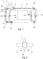
- a vehicle 1 equipped with a cleaning system 2 according to the invention which allows the cleaning of at least one glazed surface 20, 21 of the vehicle 1.
- a glazed surface can be for example a shield breeze 20 or a rear window of the vehicle, or it may be an optical surface 21 of an optical detection system 4 fitted to the vehicle 1.
- the cleaning system 2 comprises a hydraulic circulation duct 3 capable of allowing the circulation of a cleaning product and the projection devices 100 to 111 of the cleaning product arranged in the vehicle 1 to be associated respectively with the cleaning of a glazed surface 20 21.
- a projection device is specifically dedicated to the cleaning of a single glazed surface, but it will be understood that several projection devices could be dedicated to cleaning the same glazed surface, for example the screen. breeze 20, without departing from the context of the invention when a main hydraulic circulation conduit forms a hydraulic distribution bus 3 on which is connected a plurality of these projection devices.
- each of the projection devices 100 to 111 is connected by connection members to the distribution bus 3, and these projection devices are connected to this hydraulic distribution bus independently of one another, and in distinct and successive zones 90, 92 (visible on the figure 1 ) of the hydraulic distribution bus which forms a common bus to the plurality of projection devices.
- a single hydraulic distribution bus ensures the cleaning product supply of all the projection devices 100 to 111 mounted on the vehicle 1.
- the cleaning system 2 further comprises a pump 5 and a cleaning product storage tank.
- the pump 5 is configured to recover the cleaning product in the storage tank and to supply the main hydraulic pipe continuously with cleaning product. More particularly, an outlet 50 of the pump 5 is connected to a first end 30 of the hydraulic distribution bus 3.
- the hydraulic distribution bus 3 extends along the vehicle from this first end 30 second end 31.
- the second end 31 of the hydraulic distribution bus 3, opposite the first end 30, is closed so that the hydraulic distribution bus 3 forms an open hydraulic circuit.
- the hydraulic distribution bus could be configured to form a closed hydraulic circuit and the second end 31 of the hydraulic distribution bus could in this context be connected to the storage tank.
- first projection device 100 to 108 are intended to clean an optical surface of a sensor used for an automatic analysis of the road scene, that is to say an analysis by the vehicle electronics for particular driving of a device for assisting the driving and / or maneuvering of this vehicle
- second projection devices 109 to 111 are intended to clean a glass surface of the passenger compartment or an optical surface of a sensor serving only to the driver's direct analysis of the vehicle.
- the hydraulic distribution bus 3 is configured in this case so that it is one of the second projection devices, here a device associated with the cleaning of the rear window, which is disposed at the end of the hydraulic distribution bus, at its level. second end 31, that is to say in the area of the distribution bus furthest from the output 50 of the pump 5.
- the hydraulic distribution bus 3 has here a first portion 32 arranged in the front part of the vehicle, and a second portion 33 arranged in the passenger compartment, each portion winding in the corresponding part of the vehicle to distribute all the projection devices present in this part of the vehicle. It is understood that a hydraulic continuity is here made between these two portions 32, 33 since a single pump 5 is provided on the distribution bus.
- the portions 32, 33 are connected in pairs to one another via a hydraulic connector 6. More particularly, a first portion 32 and a second portion 33 of the hydraulic distribution bus 3 each carry at their end in see a hydraulic connection port 32a, 33a for their connection to the hydraulic connector 6. It may be provided that two projection devices 100 to 111 are connected to the same portion 32, 33 of the hydraulic distribution bus 3 or each to a portion 32 , 33 of the hydraulic distribution bus 3 different.
- the projection devices all have the same shape to facilitate the standardization of the cleaning system, but we can obviously adjust if necessary the shape and size of a cleaning device without leaving the context of the invention, since according to what has been described above, each projection device is hydraulically connected to the hydraulic distribution bus independently of the other projection devices.
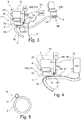
- a projection device 100 to 111 comprises a solenoid valve 7 and a nozzle 8.
- the solenoid valve 7 When the solenoid valve 7 is actuated, it allows the passage of the cleaning product flowing in the hydraulic distribution bus 3 to the nozzle 8. The cleaning product is then projected by the nozzle 8 on a glass surface 20, 21 of the system 4 optical detection associated with the projection device 100 to 111.
- the projection device comprises a hydraulic connection member 9 for its connection to the hydraulic distribution bus 3.
- the hydraulic connecting member 9 has a shape that can, on the one hand, pierce the hydraulic distribution bus 3 and on the other hand to ensure the passage of the cleaning product from the distribution bus to the nozzle 8.
- the connecting member may have the tubular shape and tapered syringe.
- a resin may be used to surround a contact zone between the hydraulic connection member 9 and the hydraulic distribution bus 3, to ensure a seal of this contact zone.
- two projection devices 100 to 111 are arranged successively along the hydraulic distribution bus 3 to be connected thereto via these hydraulic connection members 9 in successive distinct zones 90, 92. Each projection device thus comes into contact with each other. stitch on the hydraulic distribution bus as the bus is deployed in the vehicle.
- the projection device comprises a mechanical holding member 10 for attachment to the hydraulic distribution bus 3.
- the mechanical holding member 10 takes the form of a clamp that at least partially surrounds the main conduit hydraulic involved in forming the hydraulic distribution bus 3 common to the plurality of projection devices 100 to 111. It may for example provide a resiliently deforming holding member, defining in its original position a groove of substantially smaller dimensions than the duct defining the distribution bus, the operator then having to force the connecting member to deform to be able to engage on the hydraulic circulation bus, and the elastic return of the connecting member ensuring the holding in position sure the bus.
- two projection devices comprising these hydraulic connection members and these mechanical holding members cooperating with the hydraulic distribution bus 3.
- One of the projection devices has been partially represented, only by making visible these members cooperating with the hydraulic distribution bus, to illustrate the characteristic according to the invention according to which a hydraulic distribution bus serves a plurality of distribution devices, each of these devices being bites on this hydraulic distribution bus then common to the plurality of devices of distribution.
- the projection device can be connected, on the one hand, hydraulically to the hydraulic distribution bus 3 and, on the other hand, to an electronic control bus 11, which is electrically connected to a main electronic unit 200. It will be understood that it may be the same for each of the projection devices illustrated in FIG. figure 1 , so that the electronic control bus is common to all the projection devices, similarly to the hydraulic distribution bus.
- a projection device associated with an optical sensor-type optical detection system will be described below, it being understood that the characteristics relating to the hydraulic and electrical connection of the projection devices on a common bus may be reproduced for a projection device intended to to clean a glazed surface such as the windshield or the rear window.
- the projection device can be housed in a housing 12, as schematically illustrated on the figure 3 .
- the housing 12 further comprises an optical detection system 4 which has a glazed surface that the associated projection device 100 to 111 must clean.
- Such an optical detection system 4 fitted to the vehicle 1 may be a video camera or a laser scanner necessary to enable the operation of a driver assistance device. and / or when operating the vehicle 1.
- a projection device 100 to 111 When a projection device 100 to 111 is associated with such an optical detection system 4, the latter is configured to communicate via an electronic connection cable 13, separate from the electronic control bus 11, projection devices 100 to 111, with a main electronic unit 200 fitted to this vehicle 1.
- an electronic connection cable 13 By way of example, when the optical detection system 4 is a camera, this electrical connection cable 13 makes it possible to transmit a video signal to the main electronic unit 200.
- the projection devices 100 to 111 of the cleaning system 2 are electrically connected to the electronic control bus 11 independently of one another.
- the electronic control bus 11 is here a bus type LIN, it being understood that other communication protocols could be used.
- the solenoid valve 7 comprises an electronic control unit (not shown) for its control and an electrical connection terminal 15 configured to allow the connection of the projection device, and in particular of the solenoid valve, to the electronic control bus 11. More particularly , a connector 14 is provided on the electronic control bus 11 to allow a connection of the solenoid valve on the communication network continuing to the next connector and the next associated solenoid valve. The connector 14 is connected, for example by an electric wire to a first pin 150 of the electrical connection terminal 15 of the solenoid valve 7.
- a second pin 151 and a third pin 152 of the electrical connection terminal 15 are provided to receive strands from a power supply network 16 of the vehicle 1 and allowing an electrical connection to a positive pole 160, for a voltage preferably equal to 12 V, and a zero pole 161 for the grounding.
- the electronic control unit of a solenoid valve 7 is electrically connected to the electrical connection terminal 15.
- This electronic control unit is programmed to continuously analyze the data transmitted by the electronic control bus 11.
- this electronic control unit identifies an instruction issued by the main electronic unit 200, transmitted via the electronic control bus 11 and dedicated thereto, for example a command command opening the solenoid valve 7, it actuates the solenoid valve 7 associated with it and thus authorizes it to direct the cleaning product contained in the hydraulic distribution bus 3 to the nozzle 8 corresponding.
- the projection device then recovers as much cleaning product as is necessary for the cleaning of the associated glazed surface, that is to say the amount of cleaning product passing through the solenoid valve the time of its actuation by the unit. electronic steering.
- FIG 4 schematically shows the hydraulic distribution bus 3 and the electronic control bus 11 forming a single electrical and hydraulic distribution bus 17, which according to what has been previously described, is configured to serve a plurality of projection devices 100 to 111.
- the electronic control bus 11 is formed together with the hydraulic distribution bus 3.
- the hydraulic connection member 9 is advantageously arranged on the electrical and hydraulic distribution bus 17 so as not to damage the electronic control bus 11 .
- the cleaning system according to the invention is advantageous in that it comprises at least two cleaning devices arranged at a distance from each other in the vehicle and powered at least hydraulically by a hydraulic distribution bus common to these cleaning devices.
- the distribution bus is arranged in the cleaning product necessary for the operation of these cleaning devices, and it is notable according to the invention that these cleaning devices are drawn from the cleaning product circulating when given a operating instruction.
Landscapes
- Engineering & Computer Science (AREA)
- Mechanical Engineering (AREA)
- Water Supply & Treatment (AREA)
- Computer Networks & Wireless Communication (AREA)
- Signal Processing (AREA)
- Power Engineering (AREA)
- Automation & Control Theory (AREA)
- Vehicle Cleaning, Maintenance, Repair, Refitting, And Outriggers (AREA)
- Cleaning In General (AREA)
- Exhaust Gas After Treatment (AREA)
- Nozzles (AREA)
Applications Claiming Priority (1)
| Application Number | Priority Date | Filing Date | Title |
|---|---|---|---|
| FR1757611A FR3070029B1 (fr) | 2017-08-09 | 2017-08-09 | Systeme de nettoyage d'une surface vitree de vehicule |
Publications (2)
| Publication Number | Publication Date |
|---|---|
| EP3441271A1 true EP3441271A1 (de) | 2019-02-13 |
| EP3441271B1 EP3441271B1 (de) | 2021-01-20 |
Family
ID=60202154
Family Applications (1)
| Application Number | Title | Priority Date | Filing Date |
|---|---|---|---|
| EP18185645.1A Active EP3441271B1 (de) | 2017-08-09 | 2018-07-26 | Reinigungssystem einer fahrzeug-glasoberfläche |
Country Status (9)
| Country | Link |
|---|---|
| US (1) | US10661760B2 (de) |
| EP (1) | EP3441271B1 (de) |
| JP (1) | JP7274833B2 (de) |
| KR (1) | KR20190016918A (de) |
| CN (1) | CN109383456B (de) |
| BR (1) | BR102018016181A2 (de) |
| FR (1) | FR3070029B1 (de) |
| MX (1) | MX2018009628A (de) |
| RU (1) | RU2018128532A (de) |
Cited By (1)
| Publication number | Priority date | Publication date | Assignee | Title |
|---|---|---|---|---|
| WO2023030796A1 (de) * | 2021-08-30 | 2023-03-09 | Zf Cv Systems Global Gmbh | Sensorreinigungssystem, fahrzeug |
Families Citing this family (6)
| Publication number | Priority date | Publication date | Assignee | Title |
|---|---|---|---|---|
| JP7275937B2 (ja) * | 2019-07-03 | 2023-05-18 | 株式会社デンソー | センサユニット |
| CN111591252B (zh) * | 2020-03-18 | 2020-12-25 | 航天云网数据研究院(广东)有限公司 | 利用大数据存储的双模式清洁平台 |
| FR3113467B1 (fr) * | 2020-08-24 | 2023-05-12 | Valeo Systemes Dessuyage | Dispositif de projection de fluide pour le nettoyage d’une surface d’un véhicule automobile. |
| FR3120220A1 (fr) * | 2021-03-01 | 2022-09-02 | Valeo Systemes D'essuyage | Dispositif de nettoyage d’une surface vitrée |
| KR20230119322A (ko) | 2022-02-07 | 2023-08-16 | 현대자동차주식회사 | 측정유닛 클리닝 워셔 시스템 |
| KR20250060062A (ko) | 2023-10-25 | 2025-05-07 | 주식회사 마이크로시스템 | 전기습윤과 유전영동을 이용하는 능동형 자가 세정 시스템 및 방법 |
Citations (5)
| Publication number | Priority date | Publication date | Assignee | Title |
|---|---|---|---|---|
| DE10115975A1 (de) * | 2001-03-30 | 2002-10-10 | Volkswagen Ag | Verfahren und Einrichtung zur Steuerung der Reinigungsdüsen |
| US20070209687A1 (en) * | 2006-03-07 | 2007-09-13 | Fistler James D | Automotive glass washer arrangement |
| US20120266926A1 (en) | 2011-04-25 | 2012-10-25 | Asmo Co., Ltd. | Washer apparatus for vehicle |
| FR2986877A1 (fr) * | 2012-02-10 | 2013-08-16 | Peugeot Citroen Automobiles Sa | Dispositif de controle de debit par variation de section, pour un systeme de lavage de vitre de vehicule |
| JP2014037239A (ja) * | 2011-10-14 | 2014-02-27 | Denso Corp | カメラ洗浄装置 |
Family Cites Families (16)
| Publication number | Priority date | Publication date | Assignee | Title |
|---|---|---|---|---|
| JP2531883Y2 (ja) * | 1990-03-20 | 1997-04-09 | 日野自動車工業株式会社 | 自動車用ウインドウォッシャ装置 |
| JPH04133843A (ja) * | 1990-09-27 | 1992-05-07 | Nissan Motor Co Ltd | ワイパ装置 |
| DE19856174A1 (de) * | 1998-12-05 | 2000-06-15 | Mannesmann Vdo Ag | Scheibenreinigungsanlage für ein Kraftfahrzeug |
| DE10022725A1 (de) * | 2000-05-10 | 2001-11-22 | Bosch Gmbh Robert | Beheizbare Waschanlage |
| JP2008137548A (ja) * | 2006-12-04 | 2008-06-19 | Toyota Motor Corp | 車輌用ウォッシャ装置 |
| DE102007053096B4 (de) * | 2007-11-07 | 2024-12-05 | Continental Automotive Technologies GmbH | Scheibenreinigungsanlage für ein Kraftfahrzeug |
| FR2967955B1 (fr) * | 2010-11-29 | 2012-12-14 | Peugeot Citroen Automobiles Sa | Circuit de distribution de liquide lave-glace pour vehicule automobile. |
| JP5803831B2 (ja) * | 2012-07-23 | 2015-11-04 | 株式会社デンソー | 車載光学センサ用洗浄装置 |
| US9569675B2 (en) * | 2012-07-27 | 2017-02-14 | Nissan Motor Co., Ltd. | Three-dimensional object detection device, and three-dimensional object detection method |
| JP6379665B2 (ja) * | 2013-08-12 | 2018-08-29 | 株式会社デンソー | 車載光学センサ洗浄装置 |
| JP6338244B2 (ja) * | 2014-05-13 | 2018-06-06 | 株式会社デンソー | 車両用洗浄装置 |
| DE102014110064A1 (de) * | 2014-07-17 | 2016-01-21 | Valeo Systèmes d'Essuyage | Wischvorrichtung zum Reinigen einer Fahrzeugscheibe und Wischblatt für eine Wischvorrichtung |
| DE102015114928A1 (de) * | 2015-09-07 | 2017-03-09 | Valeo Systèmes d'Essuyage | Reinigungseinrichtung zum Reinigen von Fahrzeugscheiben und Wischvorrichtung |
| DE102016006039A1 (de) * | 2016-05-18 | 2016-11-17 | Daimler Ag | Reinigungseinrichtung eines Sensormoduls |
| JP6841159B2 (ja) * | 2017-05-24 | 2021-03-10 | トヨタ自動車株式会社 | 運転支援装置 |
| US10189449B2 (en) * | 2017-06-23 | 2019-01-29 | Ford Global Technologies, Llc | Vehicle cleaning |
-
2017
- 2017-08-09 FR FR1757611A patent/FR3070029B1/fr not_active Expired - Fee Related
-
2018
- 2018-07-26 EP EP18185645.1A patent/EP3441271B1/de active Active
- 2018-08-03 US US16/054,331 patent/US10661760B2/en active Active
- 2018-08-06 RU RU2018128532A patent/RU2018128532A/ru not_active Application Discontinuation
- 2018-08-08 JP JP2018149672A patent/JP7274833B2/ja active Active
- 2018-08-08 CN CN201810895506.1A patent/CN109383456B/zh active Active
- 2018-08-08 MX MX2018009628A patent/MX2018009628A/es unknown
- 2018-08-08 BR BR102018016181-4A patent/BR102018016181A2/pt not_active IP Right Cessation
- 2018-08-08 KR KR1020180092321A patent/KR20190016918A/ko not_active Abandoned
Patent Citations (5)
| Publication number | Priority date | Publication date | Assignee | Title |
|---|---|---|---|---|
| DE10115975A1 (de) * | 2001-03-30 | 2002-10-10 | Volkswagen Ag | Verfahren und Einrichtung zur Steuerung der Reinigungsdüsen |
| US20070209687A1 (en) * | 2006-03-07 | 2007-09-13 | Fistler James D | Automotive glass washer arrangement |
| US20120266926A1 (en) | 2011-04-25 | 2012-10-25 | Asmo Co., Ltd. | Washer apparatus for vehicle |
| JP2014037239A (ja) * | 2011-10-14 | 2014-02-27 | Denso Corp | カメラ洗浄装置 |
| FR2986877A1 (fr) * | 2012-02-10 | 2013-08-16 | Peugeot Citroen Automobiles Sa | Dispositif de controle de debit par variation de section, pour un systeme de lavage de vitre de vehicule |
Cited By (1)
| Publication number | Priority date | Publication date | Assignee | Title |
|---|---|---|---|---|
| WO2023030796A1 (de) * | 2021-08-30 | 2023-03-09 | Zf Cv Systems Global Gmbh | Sensorreinigungssystem, fahrzeug |
Also Published As
| Publication number | Publication date |
|---|---|
| FR3070029B1 (fr) | 2021-06-04 |
| JP7274833B2 (ja) | 2023-05-17 |
| CN109383456A (zh) | 2019-02-26 |
| BR102018016181A2 (pt) | 2019-03-26 |
| JP2019048621A (ja) | 2019-03-28 |
| US20190047521A1 (en) | 2019-02-14 |
| RU2018128532A (ru) | 2020-02-07 |
| US10661760B2 (en) | 2020-05-26 |
| CN109383456B (zh) | 2022-05-10 |
| KR20190016918A (ko) | 2019-02-19 |
| FR3070029A1 (fr) | 2019-02-15 |
| EP3441271B1 (de) | 2021-01-20 |
| MX2018009628A (es) | 2019-02-12 |
Similar Documents
| Publication | Publication Date | Title |
|---|---|---|
| EP3441271B1 (de) | Reinigungssystem einer fahrzeug-glasoberfläche | |
| EP3665046B1 (de) | Optisches fahrzeugdetektionssystem | |
| EP3441270B1 (de) | Reinigungssystem einer fahrzeug-glasoberfläche | |
| EP3006278B1 (de) | Reinigungsvorrichtung für kamera eines fahrerassistenzsystems in einem kraftfahrzeug | |
| FR3027008A1 (fr) | Dispositif de nettoyage d’une camera d’aide a la conduite d’un vehicule automobile | |
| WO2003002363A1 (fr) | Module d'equipement d'un vehicule automobile | |
| CA2799262A1 (fr) | Dispositif de raccordement electrique et hydraulique pour un systeme d'approvisionnement et/ou de distribution en lave-glace | |
| WO2020064885A1 (fr) | Module de detection pour dispositif d'aide a la conduite d'un vehicule automobile | |
| EP3250422B1 (de) | Flüssigkeitsverteilungsventil für ein flüssigkeitsverteilungssystem eines fahrzeugwäschers | |
| EP2734423B1 (de) | Stütze für befestigungsvorrichtung und waschflüssigkeitszuführvorrichtung für eine fahrzeug wischeranlage | |
| FR3089262A1 (fr) | Dispositif de distribution de fluide | |
| EP4200168B1 (de) | Fluidsprühvorrichtung zur reinigung einer oberfläche eines kraftfahrzeugs | |
| FR3085652A1 (fr) | Electrovanne d'un dispositif de nettoyage pour surface vitree | |
| EP3312062B1 (de) | Anschlussmodul für eine wischvorrichtung eines kraftfahrzeugs | |
| FR2973756A1 (fr) | Mecanisme d'essuie-vitre avec support de connectique pour l'alimentation en electricite d'autres dispositifs electriques | |
| FR3091682A1 (fr) | Embout d'extremite pour balai d’essuyage d'un vehicule automobile | |
| FR3139084A1 (fr) | Connecteur d’un système d’essuyage. | |
| FR3139086A1 (fr) | Connecteur d’un système d’essuyage. | |
| FR3113874A1 (fr) | Ensemble de détection et/ou d’émission d’un véhicule. | |
| FR3141661A1 (fr) | Système de nettoyage motorisé d’une surface optique. | |
| FR3086750A1 (fr) | Dispositif de geolocalisation de vehicule automobile | |
| FR2837761A1 (fr) | Connecteur mixte |
Legal Events
| Date | Code | Title | Description |
|---|---|---|---|
| PUAI | Public reference made under article 153(3) epc to a published international application that has entered the european phase |
Free format text: ORIGINAL CODE: 0009012 |
|
| STAA | Information on the status of an ep patent application or granted ep patent |
Free format text: STATUS: REQUEST FOR EXAMINATION WAS MADE |
|
| 17P | Request for examination filed |
Effective date: 20180726 |
|
| AK | Designated contracting states |
Kind code of ref document: A1 Designated state(s): AL AT BE BG CH CY CZ DE DK EE ES FI FR GB GR HR HU IE IS IT LI LT LU LV MC MK MT NL NO PL PT RO RS SE SI SK SM TR |
|
| AX | Request for extension of the european patent |
Extension state: BA ME |
|
| STAA | Information on the status of an ep patent application or granted ep patent |
Free format text: STATUS: EXAMINATION IS IN PROGRESS |
|
| 17Q | First examination report despatched |
Effective date: 20200207 |
|
| GRAJ | Information related to disapproval of communication of intention to grant by the applicant or resumption of examination proceedings by the epo deleted |
Free format text: ORIGINAL CODE: EPIDOSDIGR1 |
|
| STAA | Information on the status of an ep patent application or granted ep patent |
Free format text: STATUS: GRANT OF PATENT IS INTENDED |
|
| GRAP | Despatch of communication of intention to grant a patent |
Free format text: ORIGINAL CODE: EPIDOSNIGR1 |
|
| INTG | Intention to grant announced |
Effective date: 20200922 |
|
| GRAS | Grant fee paid |
Free format text: ORIGINAL CODE: EPIDOSNIGR3 |
|
| GRAA | (expected) grant |
Free format text: ORIGINAL CODE: 0009210 |
|
| STAA | Information on the status of an ep patent application or granted ep patent |
Free format text: STATUS: THE PATENT HAS BEEN GRANTED |
|
| AK | Designated contracting states |
Kind code of ref document: B1 Designated state(s): AL AT BE BG CH CY CZ DE DK EE ES FI FR GB GR HR HU IE IS IT LI LT LU LV MC MK MT NL NO PL PT RO RS SE SI SK SM TR |
|
| REG | Reference to a national code |
Ref country code: GB Ref legal event code: FG4D Free format text: NOT ENGLISH |
|
| REG | Reference to a national code |
Ref country code: CH Ref legal event code: EP |
|
| REG | Reference to a national code |
Ref country code: DE Ref legal event code: R096 Ref document number: 602018011980 Country of ref document: DE |
|
| REG | Reference to a national code |
Ref country code: AT Ref legal event code: REF Ref document number: 1356120 Country of ref document: AT Kind code of ref document: T Effective date: 20210215 |
|
| REG | Reference to a national code |
Ref country code: IE Ref legal event code: FG4D Free format text: LANGUAGE OF EP DOCUMENT: FRENCH |
|
| REG | Reference to a national code |
Ref country code: NL Ref legal event code: MP Effective date: 20210120 |
|
| REG | Reference to a national code |
Ref country code: LT Ref legal event code: MG9D |
|
| REG | Reference to a national code |
Ref country code: AT Ref legal event code: MK05 Ref document number: 1356120 Country of ref document: AT Kind code of ref document: T Effective date: 20210120 |
|
| PG25 | Lapsed in a contracting state [announced via postgrant information from national office to epo] |
Ref country code: FI Free format text: LAPSE BECAUSE OF FAILURE TO SUBMIT A TRANSLATION OF THE DESCRIPTION OR TO PAY THE FEE WITHIN THE PRESCRIBED TIME-LIMIT Effective date: 20210120 Ref country code: GR Free format text: LAPSE BECAUSE OF FAILURE TO SUBMIT A TRANSLATION OF THE DESCRIPTION OR TO PAY THE FEE WITHIN THE PRESCRIBED TIME-LIMIT Effective date: 20210421 Ref country code: HR Free format text: LAPSE BECAUSE OF FAILURE TO SUBMIT A TRANSLATION OF THE DESCRIPTION OR TO PAY THE FEE WITHIN THE PRESCRIBED TIME-LIMIT Effective date: 20210120 Ref country code: BG Free format text: LAPSE BECAUSE OF FAILURE TO SUBMIT A TRANSLATION OF THE DESCRIPTION OR TO PAY THE FEE WITHIN THE PRESCRIBED TIME-LIMIT Effective date: 20210420 Ref country code: NO Free format text: LAPSE BECAUSE OF FAILURE TO SUBMIT A TRANSLATION OF THE DESCRIPTION OR TO PAY THE FEE WITHIN THE PRESCRIBED TIME-LIMIT Effective date: 20210420 Ref country code: PT Free format text: LAPSE BECAUSE OF FAILURE TO SUBMIT A TRANSLATION OF THE DESCRIPTION OR TO PAY THE FEE WITHIN THE PRESCRIBED TIME-LIMIT Effective date: 20210520 Ref country code: LT Free format text: LAPSE BECAUSE OF FAILURE TO SUBMIT A TRANSLATION OF THE DESCRIPTION OR TO PAY THE FEE WITHIN THE PRESCRIBED TIME-LIMIT Effective date: 20210120 |
|
| PG25 | Lapsed in a contracting state [announced via postgrant information from national office to epo] |
Ref country code: AT Free format text: LAPSE BECAUSE OF FAILURE TO SUBMIT A TRANSLATION OF THE DESCRIPTION OR TO PAY THE FEE WITHIN THE PRESCRIBED TIME-LIMIT Effective date: 20210120 Ref country code: RS Free format text: LAPSE BECAUSE OF FAILURE TO SUBMIT A TRANSLATION OF THE DESCRIPTION OR TO PAY THE FEE WITHIN THE PRESCRIBED TIME-LIMIT Effective date: 20210120 Ref country code: LV Free format text: LAPSE BECAUSE OF FAILURE TO SUBMIT A TRANSLATION OF THE DESCRIPTION OR TO PAY THE FEE WITHIN THE PRESCRIBED TIME-LIMIT Effective date: 20210120 Ref country code: PL Free format text: LAPSE BECAUSE OF FAILURE TO SUBMIT A TRANSLATION OF THE DESCRIPTION OR TO PAY THE FEE WITHIN THE PRESCRIBED TIME-LIMIT Effective date: 20210120 Ref country code: SE Free format text: LAPSE BECAUSE OF FAILURE TO SUBMIT A TRANSLATION OF THE DESCRIPTION OR TO PAY THE FEE WITHIN THE PRESCRIBED TIME-LIMIT Effective date: 20210120 |
|
| PG25 | Lapsed in a contracting state [announced via postgrant information from national office to epo] |
Ref country code: IS Free format text: LAPSE BECAUSE OF FAILURE TO SUBMIT A TRANSLATION OF THE DESCRIPTION OR TO PAY THE FEE WITHIN THE PRESCRIBED TIME-LIMIT Effective date: 20210520 |
|
| REG | Reference to a national code |
Ref country code: DE Ref legal event code: R097 Ref document number: 602018011980 Country of ref document: DE |
|
| PG25 | Lapsed in a contracting state [announced via postgrant information from national office to epo] |
Ref country code: CZ Free format text: LAPSE BECAUSE OF FAILURE TO SUBMIT A TRANSLATION OF THE DESCRIPTION OR TO PAY THE FEE WITHIN THE PRESCRIBED TIME-LIMIT Effective date: 20210120 Ref country code: EE Free format text: LAPSE BECAUSE OF FAILURE TO SUBMIT A TRANSLATION OF THE DESCRIPTION OR TO PAY THE FEE WITHIN THE PRESCRIBED TIME-LIMIT Effective date: 20210120 Ref country code: SM Free format text: LAPSE BECAUSE OF FAILURE TO SUBMIT A TRANSLATION OF THE DESCRIPTION OR TO PAY THE FEE WITHIN THE PRESCRIBED TIME-LIMIT Effective date: 20210120 |
|
| PLBE | No opposition filed within time limit |
Free format text: ORIGINAL CODE: 0009261 |
|
| STAA | Information on the status of an ep patent application or granted ep patent |
Free format text: STATUS: NO OPPOSITION FILED WITHIN TIME LIMIT |
|
| PG25 | Lapsed in a contracting state [announced via postgrant information from national office to epo] |
Ref country code: RO Free format text: LAPSE BECAUSE OF FAILURE TO SUBMIT A TRANSLATION OF THE DESCRIPTION OR TO PAY THE FEE WITHIN THE PRESCRIBED TIME-LIMIT Effective date: 20210120 Ref country code: DK Free format text: LAPSE BECAUSE OF FAILURE TO SUBMIT A TRANSLATION OF THE DESCRIPTION OR TO PAY THE FEE WITHIN THE PRESCRIBED TIME-LIMIT Effective date: 20210120 Ref country code: SK Free format text: LAPSE BECAUSE OF FAILURE TO SUBMIT A TRANSLATION OF THE DESCRIPTION OR TO PAY THE FEE WITHIN THE PRESCRIBED TIME-LIMIT Effective date: 20210120 |
|
| 26N | No opposition filed |
Effective date: 20211021 |
|
| PG25 | Lapsed in a contracting state [announced via postgrant information from national office to epo] |
Ref country code: AL Free format text: LAPSE BECAUSE OF FAILURE TO SUBMIT A TRANSLATION OF THE DESCRIPTION OR TO PAY THE FEE WITHIN THE PRESCRIBED TIME-LIMIT Effective date: 20210120 Ref country code: ES Free format text: LAPSE BECAUSE OF FAILURE TO SUBMIT A TRANSLATION OF THE DESCRIPTION OR TO PAY THE FEE WITHIN THE PRESCRIBED TIME-LIMIT Effective date: 20210120 |
|
| PG25 | Lapsed in a contracting state [announced via postgrant information from national office to epo] |
Ref country code: SI Free format text: LAPSE BECAUSE OF FAILURE TO SUBMIT A TRANSLATION OF THE DESCRIPTION OR TO PAY THE FEE WITHIN THE PRESCRIBED TIME-LIMIT Effective date: 20210120 |
|
| REG | Reference to a national code |
Ref country code: CH Ref legal event code: PL |
|
| PG25 | Lapsed in a contracting state [announced via postgrant information from national office to epo] |
Ref country code: MC Free format text: LAPSE BECAUSE OF FAILURE TO SUBMIT A TRANSLATION OF THE DESCRIPTION OR TO PAY THE FEE WITHIN THE PRESCRIBED TIME-LIMIT Effective date: 20210120 |
|
| REG | Reference to a national code |
Ref country code: BE Ref legal event code: MM Effective date: 20210731 |
|
| PG25 | Lapsed in a contracting state [announced via postgrant information from national office to epo] |
Ref country code: LI Free format text: LAPSE BECAUSE OF NON-PAYMENT OF DUE FEES Effective date: 20210731 Ref country code: IT Free format text: LAPSE BECAUSE OF FAILURE TO SUBMIT A TRANSLATION OF THE DESCRIPTION OR TO PAY THE FEE WITHIN THE PRESCRIBED TIME-LIMIT Effective date: 20210120 Ref country code: CH Free format text: LAPSE BECAUSE OF NON-PAYMENT OF DUE FEES Effective date: 20210731 |
|
| PG25 | Lapsed in a contracting state [announced via postgrant information from national office to epo] |
Ref country code: IS Free format text: LAPSE BECAUSE OF FAILURE TO SUBMIT A TRANSLATION OF THE DESCRIPTION OR TO PAY THE FEE WITHIN THE PRESCRIBED TIME-LIMIT Effective date: 20210520 Ref country code: LU Free format text: LAPSE BECAUSE OF NON-PAYMENT OF DUE FEES Effective date: 20210726 |
|
| PG25 | Lapsed in a contracting state [announced via postgrant information from national office to epo] |
Ref country code: IE Free format text: LAPSE BECAUSE OF NON-PAYMENT OF DUE FEES Effective date: 20210726 Ref country code: BE Free format text: LAPSE BECAUSE OF NON-PAYMENT OF DUE FEES Effective date: 20210731 |
|
| GBPC | Gb: european patent ceased through non-payment of renewal fee |
Effective date: 20220726 |
|
| PG25 | Lapsed in a contracting state [announced via postgrant information from national office to epo] |
Ref country code: GB Free format text: LAPSE BECAUSE OF NON-PAYMENT OF DUE FEES Effective date: 20220726 |
|
| PG25 | Lapsed in a contracting state [announced via postgrant information from national office to epo] |
Ref country code: NL Free format text: LAPSE BECAUSE OF NON-PAYMENT OF DUE FEES Effective date: 20210120 Ref country code: CY Free format text: LAPSE BECAUSE OF FAILURE TO SUBMIT A TRANSLATION OF THE DESCRIPTION OR TO PAY THE FEE WITHIN THE PRESCRIBED TIME-LIMIT Effective date: 20210120 |
|
| P01 | Opt-out of the competence of the unified patent court (upc) registered |
Effective date: 20230528 |
|
| PG25 | Lapsed in a contracting state [announced via postgrant information from national office to epo] |
Ref country code: HU Free format text: LAPSE BECAUSE OF FAILURE TO SUBMIT A TRANSLATION OF THE DESCRIPTION OR TO PAY THE FEE WITHIN THE PRESCRIBED TIME-LIMIT; INVALID AB INITIO Effective date: 20180726 |
|
| PG25 | Lapsed in a contracting state [announced via postgrant information from national office to epo] |
Ref country code: MK Free format text: LAPSE BECAUSE OF FAILURE TO SUBMIT A TRANSLATION OF THE DESCRIPTION OR TO PAY THE FEE WITHIN THE PRESCRIBED TIME-LIMIT Effective date: 20210120 |
|
| PG25 | Lapsed in a contracting state [announced via postgrant information from national office to epo] |
Ref country code: TR Free format text: LAPSE BECAUSE OF FAILURE TO SUBMIT A TRANSLATION OF THE DESCRIPTION OR TO PAY THE FEE WITHIN THE PRESCRIBED TIME-LIMIT Effective date: 20210120 |
|
| PG25 | Lapsed in a contracting state [announced via postgrant information from national office to epo] |
Ref country code: MT Free format text: LAPSE BECAUSE OF FAILURE TO SUBMIT A TRANSLATION OF THE DESCRIPTION OR TO PAY THE FEE WITHIN THE PRESCRIBED TIME-LIMIT Effective date: 20210120 |
|
| PGFP | Annual fee paid to national office [announced via postgrant information from national office to epo] |
Ref country code: DE Payment date: 20250711 Year of fee payment: 8 |
|
| PGFP | Annual fee paid to national office [announced via postgrant information from national office to epo] |
Ref country code: FR Payment date: 20250730 Year of fee payment: 8 |