EP3441271A1 - System for cleaning a glazed vehicle surface - Google Patents
System for cleaning a glazed vehicle surface Download PDFInfo
- Publication number
- EP3441271A1 EP3441271A1 EP18185645.1A EP18185645A EP3441271A1 EP 3441271 A1 EP3441271 A1 EP 3441271A1 EP 18185645 A EP18185645 A EP 18185645A EP 3441271 A1 EP3441271 A1 EP 3441271A1
- Authority
- EP
- European Patent Office
- Prior art keywords
- hydraulic
- distribution bus
- bus
- cleaning
- hydraulic distribution
- Prior art date
- Legal status (The legal status is an assumption and is not a legal conclusion. Google has not performed a legal analysis and makes no representation as to the accuracy of the status listed.)
- Granted
Links
Images
Classifications
-
- B—PERFORMING OPERATIONS; TRANSPORTING
- B60—VEHICLES IN GENERAL
- B60S—SERVICING, CLEANING, REPAIRING, SUPPORTING, LIFTING, OR MANOEUVRING OF VEHICLES, NOT OTHERWISE PROVIDED FOR
- B60S1/00—Cleaning of vehicles
- B60S1/02—Cleaning windscreens, windows or optical devices
- B60S1/46—Cleaning windscreens, windows or optical devices using liquid; Windscreen washers
- B60S1/48—Liquid supply therefor
- B60S1/481—Liquid supply therefor the operation of at least part of the liquid supply being controlled by electric means
-
- B—PERFORMING OPERATIONS; TRANSPORTING
- B08—CLEANING
- B08B—CLEANING IN GENERAL; PREVENTION OF FOULING IN GENERAL
- B08B3/00—Cleaning by methods involving the use or presence of liquid or steam
- B08B3/02—Cleaning by the force of jets or sprays
-
- B—PERFORMING OPERATIONS; TRANSPORTING
- B60—VEHICLES IN GENERAL
- B60S—SERVICING, CLEANING, REPAIRING, SUPPORTING, LIFTING, OR MANOEUVRING OF VEHICLES, NOT OTHERWISE PROVIDED FOR
- B60S1/00—Cleaning of vehicles
- B60S1/02—Cleaning windscreens, windows or optical devices
- B60S1/04—Wipers or the like, e.g. scrapers
- B60S1/06—Wipers or the like, e.g. scrapers characterised by the drive
- B60S1/08—Wipers or the like, e.g. scrapers characterised by the drive electrically driven
- B60S1/0818—Wipers or the like, e.g. scrapers characterised by the drive electrically driven including control systems responsive to external conditions, e.g. by detection of moisture, dirt or the like
- B60S1/0822—Wipers or the like, e.g. scrapers characterised by the drive electrically driven including control systems responsive to external conditions, e.g. by detection of moisture, dirt or the like characterized by the arrangement or type of detection means
- B60S1/0833—Optical rain sensor
- B60S1/0844—Optical rain sensor including a camera
- B60S1/0848—Cleaning devices for cameras on vehicle
-
- B—PERFORMING OPERATIONS; TRANSPORTING
- B60—VEHICLES IN GENERAL
- B60S—SERVICING, CLEANING, REPAIRING, SUPPORTING, LIFTING, OR MANOEUVRING OF VEHICLES, NOT OTHERWISE PROVIDED FOR
- B60S1/00—Cleaning of vehicles
- B60S1/02—Cleaning windscreens, windows or optical devices
- B60S1/46—Cleaning windscreens, windows or optical devices using liquid; Windscreen washers
- B60S1/48—Liquid supply therefor
- B60S1/52—Arrangement of nozzles; Liquid spreading means
-
- B—PERFORMING OPERATIONS; TRANSPORTING
- B60—VEHICLES IN GENERAL
- B60S—SERVICING, CLEANING, REPAIRING, SUPPORTING, LIFTING, OR MANOEUVRING OF VEHICLES, NOT OTHERWISE PROVIDED FOR
- B60S1/00—Cleaning of vehicles
- B60S1/02—Cleaning windscreens, windows or optical devices
- B60S1/56—Cleaning windscreens, windows or optical devices specially adapted for cleaning other parts or devices than front windows or windscreens
- B60S1/58—Cleaning windscreens, windows or optical devices specially adapted for cleaning other parts or devices than front windows or windscreens for rear windows
-
- B—PERFORMING OPERATIONS; TRANSPORTING
- B60—VEHICLES IN GENERAL
- B60S—SERVICING, CLEANING, REPAIRING, SUPPORTING, LIFTING, OR MANOEUVRING OF VEHICLES, NOT OTHERWISE PROVIDED FOR
- B60S1/00—Cleaning of vehicles
- B60S1/62—Other vehicle fittings for cleaning
-
- H—ELECTRICITY
- H04—ELECTRIC COMMUNICATION TECHNIQUE
- H04B—TRANSMISSION
- H04B3/00—Line transmission systems
- H04B3/54—Systems for transmission via power distribution lines
- H04B3/542—Systems for transmission via power distribution lines the information being in digital form
-
- H—ELECTRICITY
- H04—ELECTRIC COMMUNICATION TECHNIQUE
- H04L—TRANSMISSION OF DIGITAL INFORMATION, e.g. TELEGRAPHIC COMMUNICATION
- H04L12/00—Data switching networks
- H04L12/28—Data switching networks characterised by path configuration, e.g. LAN [Local Area Networks] or WAN [Wide Area Networks]
- H04L12/40—Bus networks
-
- B—PERFORMING OPERATIONS; TRANSPORTING
- B60—VEHICLES IN GENERAL
- B60S—SERVICING, CLEANING, REPAIRING, SUPPORTING, LIFTING, OR MANOEUVRING OF VEHICLES, NOT OTHERWISE PROVIDED FOR
- B60S1/00—Cleaning of vehicles
- B60S1/02—Cleaning windscreens, windows or optical devices
- B60S1/56—Cleaning windscreens, windows or optical devices specially adapted for cleaning other parts or devices than front windows or windscreens
Definitions
- the invention relates to the field of cleaning systems equipping motor vehicles. It relates more particularly to the field of cleaning systems of a glazed surface of such vehicles.
- the document US2012 / 266926 describes an architecture of a cleaning system comprising a plurality of devices for projecting a cleaning product. These projection devices are arranged on the front face and / or on the rear face and / or on a mirror of the vehicle to allow the cleaning of an associated glazed surface.
- first projection devices may be actuated by a manual control initiated by a user of the vehicle and second projection devices may be actuated by an automatic control initiated by a driver assistance device and / or maneuvering that vehicle.
- the glass surfaces associated with the first projection devices correspond, for example, to the windscreen and the rear window of the vehicle, whereas the glazed surfaces associated with the second projection devices correspond, for example, to the optical surfaces of sensors intended for the assistance with driving and / or maneuvering the vehicle.
- the architecture of the cleaning system of the cited document comprises a reservoir and a pump connected to each of these projection devices via a main solenoid valve drifting the cleaning product supplied by the pump to respective pipes. associated with each of the projection devices of the vehicle.
- the projection devices are fed by the pump of the cleaning system separately from each other, the control of the solenoid valve directing the cleaning product pumped from the tank to one or the other of the pipes
- a vehicle cleaning system comprises a large number of projection devices powered by the same pump
- the number of pipes to be provided to hydraulically connect all the projection devices is important and can be problematic, in terms of complexity of mounting and cost.
- Each of the hydraulic lines for example represents a cost per meter strongly weighting the overall cost of the cleaning system.
- each of the projection devices must be electrically connected to a main electronic unit for controlling the cleaning function, and for example the triggering of the cleaning function and / or the implementation of a deployment of the projector for perform this cleaning function.
- a cleaning system comprising a large number of cables and electrical connectors.
- the present invention aims to overcome at least one of the aforementioned drawbacks and to provide a cleaning system fitted to a vehicle and to reduce its manufacturing cost while simplifying its mounting in the vehicle.
- the subject of the invention is a system for cleaning at least one glass surface of a vehicle comprising a main hydraulic distribution bus able to allow the circulation of a cleaning product from a storage tank, and at least two devices for spraying the cleaning product on the at least one glazed surface.
- the at least two projection devices are connected by hydraulic connection members to the bus of hydraulic distribution, independently of one another and in successive zones of said bus.
- the projection devices are connected to the supply path of the cleaning product independently of one another, that is to say with hydraulic connection members, for example ducts. secondary of short lengths relative to the main hydraulic conduit, specific to each projection device and connected to the main hydraulic conduit at connection points offset relative to each other.
- the cleaning system according to the invention it is possible to substantially reduce the overall cost of implantation in the vehicle of such a cleaning system.
- only one hydraulic duct is used to feed hydraulically each of the projection devices fitted to a vehicle, the hydraulic duct thus forming a distribution bus on which use dispensing devices according to the need for cleaning.
- These two projection devices are each hydraulically connected to this same hydraulic conduit along it so that each of these projection devices can be served as cleaning product by the main hydraulic conduit independently of one another.
- the cleaning system according to the invention is all the more interesting that it comprises a large number of projection devices, respectively connected to the same main hydraulic conduit, at a distance from each other along the hydraulic conduit main driving along the vehicle.
- the main hydraulic conduit acts as a hydraulic distribution bus, traveling the vehicle to hydraulically supply each of these projection devices equipping the vehicle.
- the size of the secondary hydraulic ducts, which can form the specific connecting members to each projection device, is small and the hydraulic circuit fastening constraints thus relate mainly to the main hydraulic duct, mutualized for each projection device. This advantageously makes it possible to optimize the space requirement in the vehicle of the hydraulic circuits for such cleaning systems.
- hydraulic conduits are regularly fixed on the vehicle's structural elements by fasteners, either along or through walls delimiting the passenger compartment for example, and it is understood that the reduction in the total length of the ducts ( main and secondary) reduces the number of these fasteners, and therefore the cost of parts to provide for the installation of the cleaning system in the vehicle and the time required for mounting this system.
- the cleaning system comprises a single hydraulic distribution bus and the projection devices are directly attached to this hydraulic distribution bus, the connection member specific to each projection device consisting of a stitching projection device on the hydraulic distribution bus.
- the hydraulic distribution bus forms an open hydraulic circuit.
- the cleaning product circulating in the hydraulic distribution bus is at a substantially different pressure between a first end of the hydraulic distribution bus connected to an outlet of the pump and a second end of the closed and opposite hydraulic distribution bus. at the first end, this when all the projection devices connected to this hydraulic distribution bus are actuated.
- the hydraulic distribution bus forms a closed hydraulic circuit.
- the cleaning product circulates in a closed loop and thus has a quasi constant pressure input and output of the hydraulic distribution bus, this when all the projection devices connected to the hydraulic distribution bus are actuated .
- the cleaning system comprises a pump capable of supplying the hydraulic distribution bus with cleaning product.
- the pump can feed the hydraulic distribution bus by drawing cleaning product into a storage tank of this product.
- the hydraulic distribution bus forms a closed hydraulic circuit, a first end of the hydraulic distribution bus is connected to an outlet of the pump and a second end of the hydraulic distribution bus opposite the first end is connected to an inlet of the pump .
- the hydraulic distribution bus comprises at least two portions arranged on either side of a wall and connected to one another by a hydraulic connector.
- This embodiment makes it possible to hydraulically connect two portions of the hydraulic distribution bus extending along the vehicle and forming, according to the invention, the main distribution duct, these two portions being separated by a wall of the vehicle.
- the hydraulic connector can be mounted in an opening formed in this wall.
- Such a wall may be metallic or plastic and corresponds to a wall on the distribution path of the hydraulic distribution bus running through the vehicle to serve the projection devices.
- One end of each portion of the hydraulic distribution bus to be connected to each other may carry a hydraulic connection port for connection to the hydraulic connector.
- the at least two projection devices can in particular be connected to the same portion of the hydraulic distribution bus, or be connected respectively to different portions of the hydraulic distribution bus.
- the dispensing devices are arranged so that each portion of the hydraulic distribution bus serves at least two dispensing devices.
- the hydraulic connection members specific to each projection device are formed by syringes provided for piercing the hydraulic distribution bus.
- syringe is meant a tube secured to the projection device and carrying at its free end a tip configured to pierce the hydraulic main duct forming the distribution bus, the tube being hollow to form a secondary hydraulic conduit deriving from the hydraulic distribution bus for feed the cleaning device.
- At least one of the projection devices comprises mechanical holding members on the hydraulic distribution bus. It will be understood that each of the projection devices can be fixed on the hydraulic distribution bus by a mechanical holding member of its own. Such mechanical holding members make it possible to use the hydraulic distribution bus to carry the projection devices.
- each of the projection devices comprises a solenoid valve and a nozzle.
- the hydraulic connection member and the mechanical holding member, a projection device are carried by the solenoid valve of the projection device.
- a solenoid valve may advantageously be mechanically and hydraulically connected to the hydraulic distribution bus in the same assembly operation.
- the nozzle may be of fixed or telescopic type.
- the projection device is configured so that the nozzle or nozzles of the cleaning product keep a fixed position during and between the cleaning operations, or that these projection nozzles are mounted on a telescopic body capable of take a cleaning position opposite the glazed surface to be cleaned and a retracted position.
- At least one of the projection devices is associated with an optical detection system and the projection device and the associated optical detection system are housed in a common housing.
- Such an optical detection system may be an optical sensor of the video camera or laser scanner type, necessary to allow the operation of a device for assisting in driving and / or maneuvering the vehicle.
- the glass surface of these sensors is then an optical surface formed by a protective glass exposed to the weather.
- the hydraulic connection member and the mechanical holding member of a projection device relative to the hydraulic distribution bus can be carried by the housing.
- the housing previously equipped with the projection device and the sensor can then be mechanically and hydraulically connected to the hydraulic distribution bus.
- the housing then forms a mechanical and hydraulic connection interface between the hydraulic distribution bus and the corresponding projection device.
- the cleaning system comprises an electronic control bus, the at least two projection devices being electrically connected to the electronic control bus independently of one another.
- Each projection device can thus be configured to include a hydraulic connection member to a hydraulic distribution bus, also common to all the projection devices, and an electrical connection member to an electronic control bus, again advantageously common to all projection devices.
- the electronic control bus can follow the path of the hydraulic distribution bus running through the vehicle to electrically control each of these projection devices fitted to the vehicle. This advantageously makes it possible to optimize the space requirement in the vehicle dedicated to electrical circuits for such cleaning systems.
- the electronic control bus which must be regularly fixed to the vehicle structural elements by fasteners, can share the fastening fasteners of the hydraulic distribution bus.
- the electronic control bus may be a bus operating with a line carrier type communication protocol (PLC), or for the communication protocol to be of type LIN or CAN.
- PLC line carrier type communication protocol
- the electronic control unit of a solenoid valve is configured to process a command transmitted by the electronic control bus according to the type of electronic control bus envisaged.
- the solenoid valve of the projection device comprises an electrical connection terminal intended to be connected to the electronic control bus, the solenoid valve comprising an electronic control unit for its control.
- the solenoid valve can then allow the cleaning product to pass from the hydraulic distribution bus to the nozzle to project it onto the glass surface which is associated with him.
- the electrical connection terminal has three connection pins configured to cooperate with three strands, namely, two power supply strands and an electronic control strand.
- the two power supply lines make it possible to connect the solenoid valve of the projection device corresponding to a vehicle power source, for example a low-voltage network of the 12V type, while the electronic control strand makes it possible to connect the solenoid valve of the projection device corresponding to the electronic control bus.
- the electrical connection terminal comprises only two pins to cooperate with the two single power supply lines of the bus CPL, it being understood that the principle of the technology in-line carrier current is used to convey control information to the electronic control unit of the solenoid valve via a frequency of the electrical current of the supply network.
- the hydraulic main duct is flexible.
- the hydraulic distribution bus is made of an elastic material allowing the main hydraulic conduit to follow the shapes and contours of the structural elements of the vehicle against which it must extend.
- the electronic control bus and the hydraulic distribution bus form a single electrical distribution bus and hydraulic projection devices.
- the projection devices are clearly connected to one another.
- the electronic control bus is formed in conjunction with the hydraulic distribution bus.
- the hydraulic main duct forming the hydraulic distribution bus may be formed of an extruded tube having at the center of the tube a central channel within which the cleaning product may be circulated and having on the periphery of the tube additional ducts inside which are likely to circulate each of the power supply and control of the electronic control bus.
- the additional ducts receiving the electronic control bus may be overmoulded on the tube associated with the hydraulic distribution bus.
- a power supply network of the projection devices, the electronic control bus and the hydraulic bus form a single electric and hydraulic distribution bus of the projection devices.
- the power supply network of the projection devices and the electronic control bus are formed together with the hydraulic distribution bus.
- a distribution bus makes it possible to feed the projection devices hydraulically via the hydraulic distribution bus, to electrically supply these projection devices via the supply network and to control these same projection devices via the electronic control bus.
- the design and assembly of the assembly in the vehicle is further simplified, with a circuit common to all the projection devices which extends along the vehicle and on which the projection devices are connected independently. each other, with particular areas of connection to this common circuit which are located at a distance from each other, and for a circuit that allows distribution both hydraulic and electrical.
- the power supply network of the projection devices and the electronic control bus are arranged peripherally with respect to the hydraulic main duct.
- the electronic control bus and / or the supply network are arranged in the center of the hydraulic main duct.
- the hydraulic distribution bus has an annular section for receiving in its center, in a coaxial arrangement, the electronic control bus and / or the supply network of the projection devices.
- the single electrical and hydraulic distribution bus of the projection devices is configured so that connections are regularly provided through the tube delimiting the main hydraulic conduit to allow the electrical connection of the projection devices.
- the electrical and hydraulic distribution bus may comprise at least two connected portions one to the other by an electrical and hydraulic connector.
- This particular embodiment makes it possible to electrically and hydraulically connect two portions of the distribution bus separated by a wall of the vehicle, as described above.
- the electrical and hydraulic connector can be mounted in an opening formed in this wall.
- One end of each portion of the distribution bus intended to be connected to one another can therefore carry an electrical and hydraulic connection port for its connection to the electrical and hydraulic connector.
- At least a first projection device is intended to clean an optical surface of a sensor used for an automatic analysis of the road scene, that is to say an analysis by the vehicle electronics, in particular for controlling a device for assisting the driving and / or maneuvering of this vehicle, and for at least one second projection device for cleaning a surface glazed cabin or an optical surface of a sensor for the direct analysis of the driver of the vehicle.
- the hydraulic distribution bus is arranged so that the at least one second projection device is disposed on the hydraulic distribution bus, common to each of the projection devices, to be further away from an output of the pump supplying this hydraulic distribution bus than is the at least one first projection device.
- the cleaning product circulating at the end of this open circuit farthest from the pump may have a pressure less large than that of the cleaning product circulating at the pump outlet.
- the optical detection systems associated with driving assistance systems are immaculate in order to avoid a bad analysis of the road scene detected by the on-board electronics of the vehicle whereas if the driver analyzes by him - even the detected image of the road scene, he is better able to analyze the partially tainted image without fault of judgment. Therefore, it is advantageous to place the second projection device on a portion of the hydraulic distribution bus where the pressure is less, the potential risk of non-optimal cleaning being less impacting.
- the cleaning system comprises two separate hydraulic distribution buses and two series of separate projection devices, each series of projection devices being hydraulically connected to one of the hydraulic distribution buses in accordance with this which has been previously described, that is to say with all the projection devices of this series connected to the distribution bus corresponding independently of each other.
- provision may be made to arrange a first hydraulic distribution bus and the first series of corresponding projection devices in a first part of a vehicle and the second hydraulic distribution bus and the second series of corresponding projection devices in a second part of a vehicle.
- the first part of the vehicle may be one of the lateral parts of the vehicle and the second part may be the other of the lateral parts of the vehicle, or the first part of the vehicle may be a front part of the vehicle and the second part may be a rear part of the vehicle.
- each of the projection devices of the first series is intended to clean an optical surface of a sensor used for an automatic analysis of the road scene
- each of the projection devices of the second series is intended to clean a glass surface of the passenger compartment or an optical surface of a sensor used solely for the direct analysis by the driver of the vehicle.
- the projection devices of the first series are hydraulically powered cleaning product separately from the projection devices of the second series. By distinguishing the hydraulic supply to the cleaning product for each of the first and second series of projection devices, it is possible to trigger a cleaning command for the first or second series without penalizing the triggering of a cleaning command for the other series. .
- the cleaning system comprises a first series of projection devices hydraulically connected to a first hydraulic distribution bus and a second series of projection devices hydraulically connected to a second hydraulic distribution bus
- it can be provided a same pump to feed hydraulically in cleaning product each of the first and second hydraulic distribution buses.
- a first pump is able to supply the first hydraulic distribution bus cleaning product and a second pump is able to supply the second hydraulic distribution bus cleaner.
- each of the pumps can be connected to the same container or each to a separate container.
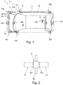
- a vehicle 1 equipped with a cleaning system 2 according to the invention which allows the cleaning of at least one glazed surface 20, 21 of the vehicle 1.
- a glazed surface can be for example a shield breeze 20 or a rear window of the vehicle, or it may be an optical surface 21 of an optical detection system 4 fitted to the vehicle 1.
- the cleaning system 2 comprises a hydraulic circulation duct 3 capable of allowing the circulation of a cleaning product and the projection devices 100 to 111 of the cleaning product arranged in the vehicle 1 to be associated respectively with the cleaning of a glazed surface 20 21.
- a projection device is specifically dedicated to the cleaning of a single glazed surface, but it will be understood that several projection devices could be dedicated to cleaning the same glazed surface, for example the screen. breeze 20, without departing from the context of the invention when a main hydraulic circulation conduit forms a hydraulic distribution bus 3 on which is connected a plurality of these projection devices.
- each of the projection devices 100 to 111 is connected by connection members to the distribution bus 3, and these projection devices are connected to this hydraulic distribution bus independently of one another, and in distinct and successive zones 90, 92 (visible on the figure 1 ) of the hydraulic distribution bus which forms a common bus to the plurality of projection devices.
- a single hydraulic distribution bus ensures the cleaning product supply of all the projection devices 100 to 111 mounted on the vehicle 1.
- the cleaning system 2 further comprises a pump 5 and a cleaning product storage tank.
- the pump 5 is configured to recover the cleaning product in the storage tank and to supply the main hydraulic pipe continuously with cleaning product. More particularly, an outlet 50 of the pump 5 is connected to a first end 30 of the hydraulic distribution bus 3.
- the hydraulic distribution bus 3 extends along the vehicle from this first end 30 second end 31.
- the second end 31 of the hydraulic distribution bus 3, opposite the first end 30, is closed so that the hydraulic distribution bus 3 forms an open hydraulic circuit.
- the hydraulic distribution bus could be configured to form a closed hydraulic circuit and the second end 31 of the hydraulic distribution bus could in this context be connected to the storage tank.
- first projection device 100 to 108 are intended to clean an optical surface of a sensor used for an automatic analysis of the road scene, that is to say an analysis by the vehicle electronics for particular driving of a device for assisting the driving and / or maneuvering of this vehicle
- second projection devices 109 to 111 are intended to clean a glass surface of the passenger compartment or an optical surface of a sensor serving only to the driver's direct analysis of the vehicle.
- the hydraulic distribution bus 3 is configured in this case so that it is one of the second projection devices, here a device associated with the cleaning of the rear window, which is disposed at the end of the hydraulic distribution bus, at its level. second end 31, that is to say in the area of the distribution bus furthest from the output 50 of the pump 5.
- the hydraulic distribution bus 3 has here a first portion 32 arranged in the front part of the vehicle, and a second portion 33 arranged in the passenger compartment, each portion winding in the corresponding part of the vehicle to distribute all the projection devices present in this part of the vehicle. It is understood that a hydraulic continuity is here made between these two portions 32, 33 since a single pump 5 is provided on the distribution bus.
- the portions 32, 33 are connected in pairs to one another via a hydraulic connector 6. More particularly, a first portion 32 and a second portion 33 of the hydraulic distribution bus 3 each carry at their end in see a hydraulic connection port 32a, 33a for their connection to the hydraulic connector 6. It may be provided that two projection devices 100 to 111 are connected to the same portion 32, 33 of the hydraulic distribution bus 3 or each to a portion 32 , 33 of the hydraulic distribution bus 3 different.
- the projection devices all have the same shape to facilitate the standardization of the cleaning system, but we can obviously adjust if necessary the shape and size of a cleaning device without leaving the context of the invention, since according to what has been described above, each projection device is hydraulically connected to the hydraulic distribution bus independently of the other projection devices.
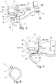
- a projection device 100 to 111 comprises a solenoid valve 7 and a nozzle 8.
- the solenoid valve 7 When the solenoid valve 7 is actuated, it allows the passage of the cleaning product flowing in the hydraulic distribution bus 3 to the nozzle 8. The cleaning product is then projected by the nozzle 8 on a glass surface 20, 21 of the system 4 optical detection associated with the projection device 100 to 111.
- the projection device comprises a hydraulic connection member 9 for its connection to the hydraulic distribution bus 3.
- the hydraulic connecting member 9 has a shape that can, on the one hand, pierce the hydraulic distribution bus 3 and on the other hand to ensure the passage of the cleaning product from the distribution bus to the nozzle 8.
- the connecting member may have the tubular shape and tapered syringe.
- a resin may be used to surround a contact zone between the hydraulic connection member 9 and the hydraulic distribution bus 3, to ensure a seal of this contact zone.
- two projection devices 100 to 111 are arranged successively along the hydraulic distribution bus 3 to be connected thereto via these hydraulic connection members 9 in successive distinct zones 90, 92. Each projection device thus comes into contact with each other. stitch on the hydraulic distribution bus as the bus is deployed in the vehicle.
- the projection device comprises a mechanical holding member 10 for attachment to the hydraulic distribution bus 3.
- the mechanical holding member 10 takes the form of a clamp that at least partially surrounds the main conduit hydraulic involved in forming the hydraulic distribution bus 3 common to the plurality of projection devices 100 to 111. It may for example provide a resiliently deforming holding member, defining in its original position a groove of substantially smaller dimensions than the duct defining the distribution bus, the operator then having to force the connecting member to deform to be able to engage on the hydraulic circulation bus, and the elastic return of the connecting member ensuring the holding in position sure the bus.
- two projection devices comprising these hydraulic connection members and these mechanical holding members cooperating with the hydraulic distribution bus 3.
- One of the projection devices has been partially represented, only by making visible these members cooperating with the hydraulic distribution bus, to illustrate the characteristic according to the invention according to which a hydraulic distribution bus serves a plurality of distribution devices, each of these devices being bites on this hydraulic distribution bus then common to the plurality of devices of distribution.
- the projection device can be connected, on the one hand, hydraulically to the hydraulic distribution bus 3 and, on the other hand, to an electronic control bus 11, which is electrically connected to a main electronic unit 200. It will be understood that it may be the same for each of the projection devices illustrated in FIG. figure 1 , so that the electronic control bus is common to all the projection devices, similarly to the hydraulic distribution bus.
- a projection device associated with an optical sensor-type optical detection system will be described below, it being understood that the characteristics relating to the hydraulic and electrical connection of the projection devices on a common bus may be reproduced for a projection device intended to to clean a glazed surface such as the windshield or the rear window.
- the projection device can be housed in a housing 12, as schematically illustrated on the figure 3 .
- the housing 12 further comprises an optical detection system 4 which has a glazed surface that the associated projection device 100 to 111 must clean.
- Such an optical detection system 4 fitted to the vehicle 1 may be a video camera or a laser scanner necessary to enable the operation of a driver assistance device. and / or when operating the vehicle 1.
- a projection device 100 to 111 When a projection device 100 to 111 is associated with such an optical detection system 4, the latter is configured to communicate via an electronic connection cable 13, separate from the electronic control bus 11, projection devices 100 to 111, with a main electronic unit 200 fitted to this vehicle 1.
- an electronic connection cable 13 By way of example, when the optical detection system 4 is a camera, this electrical connection cable 13 makes it possible to transmit a video signal to the main electronic unit 200.
- the projection devices 100 to 111 of the cleaning system 2 are electrically connected to the electronic control bus 11 independently of one another.
- the electronic control bus 11 is here a bus type LIN, it being understood that other communication protocols could be used.
- the solenoid valve 7 comprises an electronic control unit (not shown) for its control and an electrical connection terminal 15 configured to allow the connection of the projection device, and in particular of the solenoid valve, to the electronic control bus 11. More particularly , a connector 14 is provided on the electronic control bus 11 to allow a connection of the solenoid valve on the communication network continuing to the next connector and the next associated solenoid valve. The connector 14 is connected, for example by an electric wire to a first pin 150 of the electrical connection terminal 15 of the solenoid valve 7.
- a second pin 151 and a third pin 152 of the electrical connection terminal 15 are provided to receive strands from a power supply network 16 of the vehicle 1 and allowing an electrical connection to a positive pole 160, for a voltage preferably equal to 12 V, and a zero pole 161 for the grounding.
- the electronic control unit of a solenoid valve 7 is electrically connected to the electrical connection terminal 15.
- This electronic control unit is programmed to continuously analyze the data transmitted by the electronic control bus 11.
- this electronic control unit identifies an instruction issued by the main electronic unit 200, transmitted via the electronic control bus 11 and dedicated thereto, for example a command command opening the solenoid valve 7, it actuates the solenoid valve 7 associated with it and thus authorizes it to direct the cleaning product contained in the hydraulic distribution bus 3 to the nozzle 8 corresponding.
- the projection device then recovers as much cleaning product as is necessary for the cleaning of the associated glazed surface, that is to say the amount of cleaning product passing through the solenoid valve the time of its actuation by the unit. electronic steering.
- FIG 4 schematically shows the hydraulic distribution bus 3 and the electronic control bus 11 forming a single electrical and hydraulic distribution bus 17, which according to what has been previously described, is configured to serve a plurality of projection devices 100 to 111.
- the electronic control bus 11 is formed together with the hydraulic distribution bus 3.
- the hydraulic connection member 9 is advantageously arranged on the electrical and hydraulic distribution bus 17 so as not to damage the electronic control bus 11 .
- the cleaning system according to the invention is advantageous in that it comprises at least two cleaning devices arranged at a distance from each other in the vehicle and powered at least hydraulically by a hydraulic distribution bus common to these cleaning devices.
- the distribution bus is arranged in the cleaning product necessary for the operation of these cleaning devices, and it is notable according to the invention that these cleaning devices are drawn from the cleaning product circulating when given a operating instruction.
Landscapes
- Engineering & Computer Science (AREA)
- Mechanical Engineering (AREA)
- Water Supply & Treatment (AREA)
- Computer Networks & Wireless Communication (AREA)
- Signal Processing (AREA)
- Power Engineering (AREA)
- Automation & Control Theory (AREA)
- Vehicle Cleaning, Maintenance, Repair, Refitting, And Outriggers (AREA)
- Cleaning In General (AREA)
- Exhaust Gas After Treatment (AREA)
- Nozzles (AREA)
Abstract
Un système de nettoyage (2) d'au moins une surface vitrée (20, 21) de véhicule (1) comprend un bus de distribution hydraulique (3), apte à permettre la circulation d'un produit nettoyant depuis un réservoir de stockage, et au moins deux dispositifs de projection (100 à 111) du produit nettoyant sur l'au moins une surface vitrée (20, 21). Selon l'invention, les au moins deux dispositifs de projection (100 à 111) sont reliés par des organes de raccordement hydraulique au bus de distribution hydraulique (3), indépendamment l'un de l'autre et dans des zones successives dudit bus de distribution hydraulique (3).A cleaning system (2) of at least one glass surface (20, 21) of a vehicle (1) comprises a hydraulic distribution bus (3), adapted to allow the circulation of a cleaning product from a storage tank, and at least two projection devices (100 to 111) of the cleaning product on the at least one glazed surface (20, 21). According to the invention, the at least two projection devices (100 to 111) are connected by hydraulic connection members to the hydraulic distribution bus (3), independently of one another and in successive zones of said bus hydraulic distribution (3).
Description
L'invention se rapporte au domaine des systèmes de nettoyage équipant les véhicules automobiles. Elle concerne plus particulièrement le domaine des systèmes de nettoyage d'une surface vitrée de tels véhicules.The invention relates to the field of cleaning systems equipping motor vehicles. It relates more particularly to the field of cleaning systems of a glazed surface of such vehicles.
Le document
Dans de tels systèmes de nettoyage, des premiers dispositifs de projection peuvent être actionnés par une commande manuelle déclenchée par un utilisateur du véhicule et des deuxièmes dispositifs de projection peuvent être actionnés par une commande automatique déclenchée par un dispositif d'aide à la conduite et/ou à la manoeuvre de ce véhicule. Les surfaces vitrées associées aux premiers dispositifs de projection correspondent, par exemple, au pare-brise et à la lunette arrière du véhicule, alors que les surfaces vitrées associées aux deuxièmes dispositifs de projection correspondent, par exemple, aux surfaces optiques de capteurs destinés à l'aide à la conduite et/ou à la manoeuvre du véhicule.In such cleaning systems, first projection devices may be actuated by a manual control initiated by a user of the vehicle and second projection devices may be actuated by an automatic control initiated by a driver assistance device and / or maneuvering that vehicle. The glass surfaces associated with the first projection devices correspond, for example, to the windscreen and the rear window of the vehicle, whereas the glazed surfaces associated with the second projection devices correspond, for example, to the optical surfaces of sensors intended for the assistance with driving and / or maneuvering the vehicle.
Pour alimenter en produit nettoyant ces dispositifs de projection, l'architecture du système de nettoyage du document cité comporte un réservoir et une pompe reliés à chacun de ces dispositifs de projection via une électrovanne principale dérivant le produit nettoyant fourni par la pompe vers des conduites respectivement associées à chacun des dispositifs de projection du véhicule. Ainsi, dans cette architecture, les dispositifs de projection sont alimentés par la pompe du système de nettoyage distinctement les uns des autres, le pilotage de l'électrovanne dirigeant le produit nettoyant pompée du réservoir vers l'une ou l'autre des conduitesTo supply the cleaning device with these projection devices, the architecture of the cleaning system of the cited document comprises a reservoir and a pump connected to each of these projection devices via a main solenoid valve drifting the cleaning product supplied by the pump to respective pipes. associated with each of the projection devices of the vehicle. Thus, in this architecture, the projection devices are fed by the pump of the cleaning system separately from each other, the control of the solenoid valve directing the cleaning product pumped from the tank to one or the other of the pipes
Lorsqu'un système de nettoyage du véhicule comporte un grand nombre de dispositifs de projection alimentés par une même pompe, le nombre de conduites à prévoir pour relier hydrauliquement l'ensemble des dispositifs de projection est important et peut être problématique, en termes de complexité de montage et de coût. Chacune des conduites hydrauliques représente par exemple un coût au mètre pondérant fortement le coût global du système de nettoyage.When a vehicle cleaning system comprises a large number of projection devices powered by the same pump, the number of pipes to be provided to hydraulically connect all the projection devices is important and can be problematic, in terms of complexity of mounting and cost. Each of the hydraulic lines for example represents a cost per meter strongly weighting the overall cost of the cleaning system.
Par ailleurs, chacun des dispositifs de projection doit être relié électriquement à une unité électronique principale pour la commande de la fonction de nettoyage, et par exemple le déclenchement de la fonction de nettoyage et/ou la mise en oeuvre d'un déploiement du projecteur pour réaliser cette fonction de nettoyage. Là encore, pour permettre de relier électriquement chacun des dispositifs de projection à l'unité électronique principale, il est nécessaire de prévoir un système de nettoyage comportant un grand nombre de câbles et de connectiques électriques. Un agencement dans lequel un câble est tiré entre l'unité électronique principale et chacun des dispositifs de projection représente là encore un coût au mètre déterminant le coût global du système de nettoyage.Furthermore, each of the projection devices must be electrically connected to a main electronic unit for controlling the cleaning function, and for example the triggering of the cleaning function and / or the implementation of a deployment of the projector for perform this cleaning function. Again, to allow to electrically connect each of the projection devices to the main electronic unit, it is necessary to provide a cleaning system comprising a large number of cables and electrical connectors. An arrangement in which a cable is pulled between the main electronic unit and each of the projection devices again represents a cost per meter determining the overall cost of the cleaning system.
Dans un contexte de développement des véhicules, et par exemple les véhicules autonomes, où le nombre de capteurs est amené à être de plus en plus important sur le pourtour du véhicule, on comprend que ces inconvénients doivent être considérés.In a context of vehicle development, and for example autonomous vehicles, where the number of sensors is brought to be more and more important around the vehicle, it is understood that these drawbacks must be considered.
La présente invention a pour but de pallier à au moins l'un des inconvénients précités et de proposer un système de nettoyage équipant un véhicule et permettant de réduire son coût de fabrication tout en simplifiant son montage dans le véhicule.The present invention aims to overcome at least one of the aforementioned drawbacks and to provide a cleaning system fitted to a vehicle and to reduce its manufacturing cost while simplifying its mounting in the vehicle.
A cet effet, l'invention a pour objet un système de nettoyage d'au moins une surface vitrée de véhicule comprenant un bus de distribution hydraulique principal apte à permettre la circulation d'un produit nettoyant depuis un réservoir de stockage, et au moins deux dispositifs de projection du produit nettoyant sur l'au moins une surface vitrée. Selon l'invention, les au moins deux dispositifs de projection sont reliés par des organes de raccordement hydraulique au bus de distribution hydraulique, indépendamment l'un de l'autre et dans des zones successives dudit bus.To this end, the subject of the invention is a system for cleaning at least one glass surface of a vehicle comprising a main hydraulic distribution bus able to allow the circulation of a cleaning product from a storage tank, and at least two devices for spraying the cleaning product on the at least one glazed surface. According to the invention, the at least two projection devices are connected by hydraulic connection members to the bus of hydraulic distribution, independently of one another and in successive zones of said bus.
On comprendra par :
- « bus de distribution hydraulique », un conduit permettant l'acheminement du produit nettoyant,
- « produit nettoyant », un produit liquide ou gazeux pouvant être projeté sur une surface vitrée en vue du nettoyage de celle-ci, un tel produit pouvant être indifféremment dans la présente invention de l'eau, du liquide de nettoyage lave-glace, ou encore de l'air,
- « surface vitrée », une surface transparente pouvant être d'une part une des vitres de l'habitacle du véhicule et notamment un pare-brise ou une lunette arrière, ou d'autre part une surface optique d'un système de détection optique équipant le véhicule ; notamment, on peut prévoir que la surface vitrée soit réalisée en verre ou bien en un plastique transparent de type Plexiglas.
- 'Hydraulic distribution bus' means a conduit for conveying the cleaning product,
- "Cleaning product", a liquid or gaseous product that can be projected on a glass surface for the purpose of cleaning it, such a product may be indifferently in the present invention water, windshield cleaning liquid, or still air,
- "Glazed surface", a transparent surface that can be on the one hand one of the windows of the passenger compartment of the vehicle and in particular a windshield or a rear window, or on the other hand an optical surface of an optical detection system equipping the vehicle ; in particular, it can be provided that the glass surface is made of glass or a transparent plastic type Plexiglas.
Selon l'invention, il est notable que les dispositifs de projection sont raccordés au chemin d'alimentation du produit nettoyant indépendamment l'un de l'autre, c'est-à-dire avec des organes de raccordement hydraulique, par exemple des conduits secondaires de faibles longueurs par rapport au conduit hydraulique principal, propres à chaque dispositif de projection et raccordés sur le conduit hydraulique principal en des points de connexion décalés les uns par rapport aux autres.According to the invention, it is notable that the projection devices are connected to the supply path of the cleaning product independently of one another, that is to say with hydraulic connection members, for example ducts. secondary of short lengths relative to the main hydraulic conduit, specific to each projection device and connected to the main hydraulic conduit at connection points offset relative to each other.
Grâce au système de nettoyage selon l'invention, il est possible de réduire sensiblement le coût global de l'implantation dans le véhicule d'un tel système de nettoyage. En effet, contrairement à l'architecture de systèmes de nettoyage connus, il n'est utilisé qu'un conduit hydraulique pour alimenter hydrauliquement chacun des dispositifs de projection équipant un véhicule, le conduit hydraulique formant de la sorte un bus de distribution sur lequel viennent se servir les dispositifs de distribution en fonction du besoin de nettoyage. Ces deux dispositifs de projection sont chacun reliés hydrauliquement à ce même conduit hydraulique le long de celui-ci de sorte que chacun de ces dispositifs de projection peut être desservi en produit nettoyant par le conduit hydraulique principal indépendamment l'un de l'autre. On comprend que le système de nettoyage selon l'invention est d'autant plus intéressant qu'il comporte un grand nombre de dispositifs de projection, raccordés respectivement sur un même conduit hydraulique principal, à distance les uns des autres le long de ce conduit hydraulique principal circulant le long du véhicule.Thanks to the cleaning system according to the invention, it is possible to substantially reduce the overall cost of implantation in the vehicle of such a cleaning system. Indeed, unlike the architecture of known cleaning systems, only one hydraulic duct is used to feed hydraulically each of the projection devices fitted to a vehicle, the hydraulic duct thus forming a distribution bus on which use dispensing devices according to the need for cleaning. These two projection devices are each hydraulically connected to this same hydraulic conduit along it so that each of these projection devices can be served as cleaning product by the main hydraulic conduit independently of one another. It is understood that the cleaning system according to the invention is all the more interesting that it comprises a large number of projection devices, respectively connected to the same main hydraulic conduit, at a distance from each other along the hydraulic conduit main driving along the vehicle.
De la sorte, il est notable selon l'invention que l'on simplifie grandement les circuits hydrauliques d'un système de nettoyage équipant un véhicule. En effet, selon l'invention, le conduit hydraulique principal joue le rôle de bus de distribution hydraulique, en parcourant le véhicule pour alimenter hydrauliquement chacun de ces dispositifs de projection équipant le véhicule. La dimension des conduits hydrauliques secondaires, pouvant former les organes de raccordement spécifiques à chaque dispositif de projection, est petite et les contraintes de fixation du circuit hydraulique portent ainsi surtout sur le conduit hydraulique principal, mutualisé pour chaque dispositif de projection. Ceci permet avantageusement d'optimiser l'encombrement dans le véhicule des circuits hydrauliques pour de tels systèmes de nettoyage.In this way, it is notable according to the invention that greatly simplifies the hydraulic circuits of a cleaning system equipping a vehicle. Indeed, according to the invention, the main hydraulic conduit acts as a hydraulic distribution bus, traveling the vehicle to hydraulically supply each of these projection devices equipping the vehicle. The size of the secondary hydraulic ducts, which can form the specific connecting members to each projection device, is small and the hydraulic circuit fastening constraints thus relate mainly to the main hydraulic duct, mutualized for each projection device. This advantageously makes it possible to optimize the space requirement in the vehicle of the hydraulic circuits for such cleaning systems.
Par ailleurs, les conduits hydrauliques sont régulièrement fixés sur des éléments de structure du véhicule par des attaches, que ce soit le long ou à travers de parois délimitant l'habitacle par exemple, et on comprend que la diminution de la longueur totale des conduits (principal et secondaires) permet de diminuer le nombre de ces attaches, et donc le coût des pièces à prévoir pour l'installation du système de nettoyage dans le véhicule et le temps nécessaire pour le montage de ce système.Furthermore, the hydraulic conduits are regularly fixed on the vehicle's structural elements by fasteners, either along or through walls delimiting the passenger compartment for example, and it is understood that the reduction in the total length of the ducts ( main and secondary) reduces the number of these fasteners, and therefore the cost of parts to provide for the installation of the cleaning system in the vehicle and the time required for mounting this system.
Selon une caractéristique particulière de l'invention, le système de nettoyage comprend un unique bus de distribution hydraulique et les dispositifs de projection sont directement fixés sur ce bus de distribution hydraulique, l'organe de raccordement spécifique à chaque dispositif de projection consistant en un piquage du dispositif de projection sur le bus de distribution hydraulique. Grâce à cette caractéristique, il est possible de simplifier encore davantage les circuits hydrauliques d'un système de nettoyage équipant un véhicule en parcourant le véhicule pour alimenter hydrauliquement chacun des dispositifs de projection de ce véhicule.According to a particular characteristic of the invention, the cleaning system comprises a single hydraulic distribution bus and the projection devices are directly attached to this hydraulic distribution bus, the connection member specific to each projection device consisting of a stitching projection device on the hydraulic distribution bus. With this feature, it is possible to further simplify the hydraulic circuits of a cleaning system fitted to a vehicle by traveling through the vehicle to hydraulically feed each of the projection devices of this vehicle.
Selon un mode de réalisation de l'invention, le bus de distribution hydraulique forme un circuit hydraulique ouvert. En d'autres termes, le produit nettoyant circulant dans le bus de distribution hydraulique est à une pression sensiblement différente entre une première extrémité du bus de distribution hydraulique reliée à une sortie de la pompe et une deuxième extrémité du bus de distribution hydraulique fermée et opposée à la première extrémité, ceci lorsque tous les dispositifs de projection reliés à ce bus de distribution hydraulique sont actionnés.According to one embodiment of the invention, the hydraulic distribution bus forms an open hydraulic circuit. In other words, the cleaning product circulating in the hydraulic distribution bus is at a substantially different pressure between a first end of the hydraulic distribution bus connected to an outlet of the pump and a second end of the closed and opposite hydraulic distribution bus. at the first end, this when all the projection devices connected to this hydraulic distribution bus are actuated.
On pourra envisager que le bus de distribution hydraulique forme un circuit hydraulique fermé. En d'autres termes, le produit nettoyant circule dans une boucle fermée et présente de la sorte une pression quasi constante en entrée et en sortie du bus de distribution hydraulique, ceci lorsque tous les dispositifs de projection reliés à ce bus de distribution hydraulique sont actionnés.It can be envisaged that the hydraulic distribution bus forms a closed hydraulic circuit. In other words, the cleaning product circulates in a closed loop and thus has a quasi constant pressure input and output of the hydraulic distribution bus, this when all the projection devices connected to the hydraulic distribution bus are actuated .
Selon une caractéristique de l'invention, le système de nettoyage comprend une pompe apte à alimenter le bus de distribution hydraulique en produit nettoyant. Notamment, la pompe peut alimenter le bus de distribution hydraulique en puisant du produit nettoyant dans un réservoir de stockage de ce produit. Lorsque le bus de distribution hydraulique forme un circuit hydraulique fermé, une première extrémité du bus de distribution hydraulique est reliée à une sortie de la pompe et une deuxième extrémité du bus de distribution hydraulique opposée à la première extrémité est reliée à une entrée de la pompe.According to one characteristic of the invention, the cleaning system comprises a pump capable of supplying the hydraulic distribution bus with cleaning product. In particular, the pump can feed the hydraulic distribution bus by drawing cleaning product into a storage tank of this product. When the hydraulic distribution bus forms a closed hydraulic circuit, a first end of the hydraulic distribution bus is connected to an outlet of the pump and a second end of the hydraulic distribution bus opposite the first end is connected to an inlet of the pump .
Selon une caractéristique de l'invention, le bus de distribution hydraulique comprend au moins deux portions agencées de part et d'autre d'une paroi et reliées l'une à l'autre par un connecteur hydraulique. Ce mode de réalisation permet de relier hydrauliquement deux portions du bus de distribution hydraulique s'étendant le long du véhicule et formant selon l'invention le conduit principal de distribution, ces deux portions étant séparées par une paroi du véhicule. Le connecteur hydraulique peut être monté dans une ouverture formée dans cette paroi. Une telle paroi peut être métallique ou plastique et correspond à une paroi sur le chemin de distribution du bus de distribution hydraulique parcourant le véhicule pour desservir les dispositifs de projection.According to one characteristic of the invention, the hydraulic distribution bus comprises at least two portions arranged on either side of a wall and connected to one another by a hydraulic connector. This embodiment makes it possible to hydraulically connect two portions of the hydraulic distribution bus extending along the vehicle and forming, according to the invention, the main distribution duct, these two portions being separated by a wall of the vehicle. The hydraulic connector can be mounted in an opening formed in this wall. Such a wall may be metallic or plastic and corresponds to a wall on the distribution path of the hydraulic distribution bus running through the vehicle to serve the projection devices.
Une extrémité de chaque portion du bus de distribution hydraulique destinée à être raccordée l'une à l'autre peut porter un port de connexion hydraulique pour son raccordement au connecteur hydraulique.One end of each portion of the hydraulic distribution bus to be connected to each other may carry a hydraulic connection port for connection to the hydraulic connector.
Dans ce contexte de conduit principal de distribution, les au moins deux dispositifs de projection peuvent notamment être reliés à une même portion du bus de distribution hydraulique, ou être reliés respectivement à des portions différentes du bus de distribution hydraulique. Notamment, on pourra prévoir que les dispositifs de distribution sont agencés de sorte que chaque portion du bus de distribution hydraulique dessert au moins deux dispositifs de distribution.In this context of main distribution channel, the at least two projection devices can in particular be connected to the same portion of the hydraulic distribution bus, or be connected respectively to different portions of the hydraulic distribution bus. In particular, it can be provided that the dispensing devices are arranged so that each portion of the hydraulic distribution bus serves at least two dispensing devices.
Selon une caractéristique de l'invention, les organes de raccordement hydraulique spécifiques à chaque dispositif de projection sont formés par des seringues prévues pour percer le bus de distribution hydraulique. Par seringue, on entend un tube solidaire du dispositif de projection et portant à son extrémité libre une pointe configurée pour percer le conduit principal hydraulique formant le bus de distribution, le tube étant creux pour former un conduit hydraulique secondaire dérivant du bus de distribution hydraulique pour alimenter le dispositif de nettoyage.According to one characteristic of the invention, the hydraulic connection members specific to each projection device are formed by syringes provided for piercing the hydraulic distribution bus. By syringe, is meant a tube secured to the projection device and carrying at its free end a tip configured to pierce the hydraulic main duct forming the distribution bus, the tube being hollow to form a secondary hydraulic conduit deriving from the hydraulic distribution bus for feed the cleaning device.
Selon une caractéristique de l'invention, au moins un des dispositifs de projection comprend des organes de maintien mécanique sur le bus de distribution hydraulique. On comprendra que chacun des dispositifs de projection peut être fixé sur le bus de distribution hydraulique par un organe de maintien mécanique qui lui est propre. De tels organes de maintien mécanique permettent d'utiliser le bus de distribution hydraulique pour porter les dispositifs de projection.According to a feature of the invention, at least one of the projection devices comprises mechanical holding members on the hydraulic distribution bus. It will be understood that each of the projection devices can be fixed on the hydraulic distribution bus by a mechanical holding member of its own. Such mechanical holding members make it possible to use the hydraulic distribution bus to carry the projection devices.
Selon une caractéristique de l'invention, chacun des dispositifs de projection comprend une électrovanne et un gicleur.According to one characteristic of the invention, each of the projection devices comprises a solenoid valve and a nozzle.
Selon une caractéristique de l'invention, l'organe de raccordement hydraulique et l'organe de maintien mécanique, d'un dispositif de projection sont portés par l'électrovanne de ce dispositif de projection. Une telle électrovanne peut être avantageusement reliée mécaniquement et hydrauliquement au bus de distribution hydraulique dans une même opération d'assemblage.According to a characteristic of the invention, the hydraulic connection member and the mechanical holding member, a projection device are carried by the solenoid valve of the projection device. Such a solenoid valve may advantageously be mechanically and hydraulically connected to the hydraulic distribution bus in the same assembly operation.
Le gicleur peut être de type fixe ou bien télescopique. En d'autres termes, le dispositif de projection est configuré pour que la ou les buses de projection du produit nettoyant gardent une position fixe pendant et entre les opérations de nettoyage, ou bien que ces buses de projection soient montées sur un corps télescopique susceptible de prendre une position de nettoyage en regard de la surface vitrée à nettoyer et une position escamotée.The nozzle may be of fixed or telescopic type. In other words, the projection device is configured so that the nozzle or nozzles of the cleaning product keep a fixed position during and between the cleaning operations, or that these projection nozzles are mounted on a telescopic body capable of take a cleaning position opposite the glazed surface to be cleaned and a retracted position.
Selon une caractéristique de l'invention, au moins un des dispositifs de projection est associé à un système de détection optique et le dispositif de projection et le système de détection optique associé sont logés dans un boîtier commun.According to one characteristic of the invention, at least one of the projection devices is associated with an optical detection system and the projection device and the associated optical detection system are housed in a common housing.
Un tel système de détection optique peut être un capteur optique du type caméra vidéo ou encore scanner laser, nécessaire pour permettre le fonctionnement d'un dispositif d'aide à la conduite et/ou à la manoeuvre du véhicule. La surface vitrée de ces capteurs est alors une surface optique formée par un verre de protection exposé aux intempéries.Such an optical detection system may be an optical sensor of the video camera or laser scanner type, necessary to allow the operation of a device for assisting in driving and / or maneuvering the vehicle. The glass surface of these sensors is then an optical surface formed by a protective glass exposed to the weather.
Dans ce contexte particulier de la présence d'un boîtier commun, l'organe de raccordement hydraulique et l'organe de maintien mécanique d'un dispositif de projection par rapport au bus de distribution hydraulique peuvent être portés par le boîtier. Le boîtier préalablement équipé du dispositif de projection et du capteur peut alors être relié mécaniquement et hydrauliquement au bus de distribution hydraulique. Le boîtier forme alors une interface de connexion mécanique et hydraulique entre le bus de distribution hydraulique et le dispositif de projection correspondant.In this particular context of the presence of a common housing, the hydraulic connection member and the mechanical holding member of a projection device relative to the hydraulic distribution bus can be carried by the housing. The housing previously equipped with the projection device and the sensor can then be mechanically and hydraulically connected to the hydraulic distribution bus. The housing then forms a mechanical and hydraulic connection interface between the hydraulic distribution bus and the corresponding projection device.
Selon une caractéristique de l'invention, le système de nettoyage comprend un bus de commande électronique, les au moins deux dispositifs de projection étant reliés électriquement au bus de commande électronique indépendamment l'un de l'autre.According to a characteristic of the invention, the cleaning system comprises an electronic control bus, the at least two projection devices being electrically connected to the electronic control bus independently of one another.
Chaque dispositif de projection peut ainsi être configuré pour comporter un organe de raccordement hydraulique à un bus de distribution hydraulique, par ailleurs commun à tous les dispositifs de projection, et un organe de raccordement électrique à un bus de commande électronique, là encore avantageusement commun à tous les dispositifs de projection.Each projection device can thus be configured to include a hydraulic connection member to a hydraulic distribution bus, also common to all the projection devices, and an electrical connection member to an electronic control bus, again advantageously common to all projection devices.
On participe ainsi à réduire encore davantage le coût global d'un tel système de nettoyage. En effet, contrairement à l'architecture de systèmes de nettoyage connus, il n'est utilisé qu'un bus de commande électronique pour commander les au moins deux dispositifs de projection équipant le véhicule. Selon une caractéristique de l'invention, le bus de commande électronique peut suivre le chemin du bus de distribution hydraulique parcourant le véhicule pour commander électriquement chacun de ces dispositifs de projection équipant le véhicule. Ceci permet avantageusement d'optimiser l'encombrement dans le véhicule dédié aux circuits électriques pour de tels systèmes de nettoyage. En pratique, le bus de commande électronique, qui doit être régulièrement fixé sur les éléments de structure du véhicule par des attaches, peut partager les attaches de fixation du bus de distribution hydraulique.This helps to further reduce the overall cost of such a cleaning system. Indeed, unlike the architecture of known cleaning systems, only an electronic control bus is used to control the at least two projection devices equipping the vehicle. According to one characteristic of the invention, the electronic control bus can follow the path of the hydraulic distribution bus running through the vehicle to electrically control each of these projection devices fitted to the vehicle. This advantageously makes it possible to optimize the space requirement in the vehicle dedicated to electrical circuits for such cleaning systems. In practice, the electronic control bus, which must be regularly fixed to the vehicle structural elements by fasteners, can share the fastening fasteners of the hydraulic distribution bus.
Selon différents modes de mise en oeuvre de l'invention, on pourra prévoir que le bus de commande électronique est un bus fonctionnant avec un protocole de communication de type courant porteur en ligne (CPL), ou bien que le protocole de communication est de type LIN ou CAN.According to various embodiments of the invention, provision may be made for the electronic control bus to be a bus operating with a line carrier type communication protocol (PLC), or for the communication protocol to be of type LIN or CAN.
On comprendra que l'unité électronique de pilotage d'une électrovanne est configurée pour traiter une commande transmise par le bus de commande électronique selon le type de bus de commande électronique envisagée.It will be understood that the electronic control unit of a solenoid valve is configured to process a command transmitted by the electronic control bus according to the type of electronic control bus envisaged.
Selon une autre caractéristique de l'invention, l'électrovanne du dispositif de projection comprend une borne de connexion électrique destinée à être reliée au bus de commande électronique, l'électrovanne comprenant une unité électronique de pilotage pour sa commande. Lorsqu'un ordre de commande automatique en nettoyage est reçu par l'électrovanne via le bus de commande électronique, celle-ci peut alors autoriser le passage du produit nettoyant depuis le bus de distribution hydraulique vers le gicleur pour le projeter sur la surface vitrée qui lui est associée.According to another characteristic of the invention, the solenoid valve of the projection device comprises an electrical connection terminal intended to be connected to the electronic control bus, the solenoid valve comprising an electronic control unit for its control. When an automatic cleaning control command is received by the solenoid valve via the electronic control bus, it can then allow the cleaning product to pass from the hydraulic distribution bus to the nozzle to project it onto the glass surface which is associated with him.
Plus particulièrement, la borne de connexion électrique comporte trois broches de connexion configurées pour coopérer avec trois brins, à savoir, deux brins d'alimentation électrique et un brin de commande électronique.More particularly, the electrical connection terminal has three connection pins configured to cooperate with three strands, namely, two power supply strands and an electronic control strand.
Les deux brins d'alimentation permettent de relier l'électrovanne du dispositif de projection correspondant à une source d'alimentation du véhicule, par exemple un réseau basse tension de type 12V, alors que le brin de commande électronique permet de relier l'électrovanne du dispositif de projection correspondant au bus de commande électronique.The two power supply lines make it possible to connect the solenoid valve of the projection device corresponding to a vehicle power source, for example a low-voltage network of the 12V type, while the electronic control strand makes it possible to connect the solenoid valve of the projection device corresponding to the electronic control bus.
Lorsque le bus de commande électronique est un bus de type CPL, il peut être prévu que la borne de connexion électrique comporte uniquement deux broches pour coopérer avec les deux uniques brins d'alimentation électrique du bus CPL, étant entendu que le principe de la technologie de courant porteur en ligne permet de transporter une information de commande à l'unité électronique de pilotage de l'électrovanne par l'intermédiaire d'une fréquence du courant électrique du réseau d'alimentation.When the electronic control bus is a CPL type bus, it can be provided that the electrical connection terminal comprises only two pins to cooperate with the two single power supply lines of the bus CPL, it being understood that the principle of the technology in-line carrier current is used to convey control information to the electronic control unit of the solenoid valve via a frequency of the electrical current of the supply network.
Avantageusement, le conduit principal hydraulique est flexible. En d'autres termes, le bus de distribution hydraulique est réalisé dans une matière élastique permettant de faire suivre au conduit principal hydraulique les formes et contours des éléments de structure du véhicule contre lesquels il doit s'étendre.Advantageously, the hydraulic main duct is flexible. In other words, the hydraulic distribution bus is made of an elastic material allowing the main hydraulic conduit to follow the shapes and contours of the structural elements of the vehicle against which it must extend.
Selon un mode de réalisation particulier de l'invention, le bus de commande électronique et le bus de distribution hydraulique forment un même bus de distribution électrique et hydraulique des dispositifs de projection. Sur ce bus de distribution électrique et hydraulique viennent se connecter distinctement les uns des autres les dispositifs de projection. En d'autres termes, le bus de commande électronique est formé conjointement avec le bus de distribution hydraulique. Grâce à ce mode de réalisation particulier, il est possible de simplifier encore l'assemblage du système de nettoyage dans le véhicule.According to a particular embodiment of the invention, the electronic control bus and the hydraulic distribution bus form a single electrical distribution bus and hydraulic projection devices. On this electric and hydraulic distribution bus, the projection devices are clearly connected to one another. In other words, the electronic control bus is formed in conjunction with the hydraulic distribution bus. With this particular embodiment, it is possible to further simplify the assembly of the cleaning system in the vehicle.
Dans ce contexte, le conduit principal hydraulique formant le bus de distribution hydraulique peut être formé d'un tube extrudé présentant au centre du tube un canal central à l'intérieur duquel est susceptible de circuler le produit nettoyant et présentant sur la périphérie du tube des conduites additionnelles à l'intérieur desquelles sont susceptibles de circuler chacun des brins d'alimentation et de commande du bus de commande électronique. En variante, les conduites additionnelles recevant le bus de commande électronique peuvent être surmoulées sur le tube associé au bus de distribution hydraulique.In this context, the hydraulic main duct forming the hydraulic distribution bus may be formed of an extruded tube having at the center of the tube a central channel within which the cleaning product may be circulated and having on the periphery of the tube additional ducts inside which are likely to circulate each of the power supply and control of the electronic control bus. As a variant, the additional ducts receiving the electronic control bus may be overmoulded on the tube associated with the hydraulic distribution bus.
Selon une caractéristique de l'invention, un réseau d'alimentation des dispositifs de projection, le bus de commande électronique et le bus hydraulique forment un unique bus de distribution électrique et hydraulique des dispositifs de projection. En d'autres termes, le réseau d'alimentation des dispositifs de projection et le bus de commande électronique sont formés conjointement avec le bus de distribution hydraulique. On comprendra alors qu'un tel bus de distribution permet d'alimenter hydrauliquement les dispositifs de projection via le bus de distribution hydraulique, d'alimenter électriquement ces dispositifs de projection via le réseau d'alimentation et de commander ces mêmes dispositifs de projection via le bus de commande électronique. De la sorte, on simplifie là encore la conception et le montage de l'ensemble dans le véhicule, avec un circuit commun à tous les dispositifs de projection qui s'étend le long du véhicule et sur lequel les dispositifs de projection sont raccordés indépendamment les uns des autres, avec notamment des zones de raccordement à ce circuit commun qui sont situées à distance les unes des autres, et ce pour un circuit qui permet la distribution aussi bien hydraulique qu'électrique.According to a characteristic of the invention, a power supply network of the projection devices, the electronic control bus and the hydraulic bus form a single electric and hydraulic distribution bus of the projection devices. In other words, the power supply network of the projection devices and the electronic control bus are formed together with the hydraulic distribution bus. It will then be understood that such a distribution bus makes it possible to feed the projection devices hydraulically via the hydraulic distribution bus, to electrically supply these projection devices via the supply network and to control these same projection devices via the electronic control bus. In this way, the design and assembly of the assembly in the vehicle is further simplified, with a circuit common to all the projection devices which extends along the vehicle and on which the projection devices are connected independently. each other, with particular areas of connection to this common circuit which are located at a distance from each other, and for a circuit that allows distribution both hydraulic and electrical.
Comme ce qui a été décrit précédemment, on pourra envisager que le réseau d'alimentation des dispositifs de projection et le bus de commande électronique sont disposés de façon périphérique par rapport au conduit principal hydraulique.As described above, it can be envisaged that the power supply network of the projection devices and the electronic control bus are arranged peripherally with respect to the hydraulic main duct.
Par ailleurs, on peut prévoir une variante de réalisation selon laquelle le bus de commande électronique et/ou le réseau d'alimentation sont agencés au centre du conduit principal hydraulique. On comprendra alors que le bus de distribution hydraulique présente une section annulaire pour recevoir en son centre, dans un agencement coaxial, le bus de commande électronique et/ou le réseau d'alimentation des dispositifs de projection. Dans ce cas, on comprend que l'unique bus de distribution électrique et hydraulique des dispositifs de projection est configuré pour que des piquages sont régulièrement prévus à travers le tube délimitant le conduit hydraulique principal pour permettre le raccordement électrique des dispositifs de projection.Furthermore, it is possible to provide an alternative embodiment in which the electronic control bus and / or the supply network are arranged in the center of the hydraulic main duct. It will be understood that the hydraulic distribution bus has an annular section for receiving in its center, in a coaxial arrangement, the electronic control bus and / or the supply network of the projection devices. In this case, it is understood that the single electrical and hydraulic distribution bus of the projection devices is configured so that connections are regularly provided through the tube delimiting the main hydraulic conduit to allow the electrical connection of the projection devices.
Selon le mode de réalisation particulier dans lequel le bus de commande électronique et le bus de distribution hydraulique forment un même bus de distribution électrique et hydraulique des dispositifs de projection, le bus de distribution électrique et hydraulique peut comprendre au moins deux portions reliées l'une à l'autre par un connecteur électrique et hydraulique. Ce mode de réalisation particulier permet de relier électriquement et hydrauliquement deux portions du bus de distribution séparées par une paroi du véhicule, telle que décrite précédemment. Le connecteur électrique et hydraulique peut être monté dans une ouverture formée dans cette paroi. Une extrémité de chaque portion du bus de distribution destinée à être raccordée l'une à l'autre peut dès lors porter un port de connexion électrique et hydraulique pour son raccordement au connecteur électrique et hydraulique.According to the particular embodiment in which the electronic control bus and the hydraulic distribution bus form the same electrical and hydraulic distribution bus of the projection devices, the electrical and hydraulic distribution bus may comprise at least two connected portions one to the other by an electrical and hydraulic connector. This particular embodiment makes it possible to electrically and hydraulically connect two portions of the distribution bus separated by a wall of the vehicle, as described above. The electrical and hydraulic connector can be mounted in an opening formed in this wall. One end of each portion of the distribution bus intended to be connected to one another can therefore carry an electrical and hydraulic connection port for its connection to the electrical and hydraulic connector.
Selon d'autres caractéristiques de l'invention, il peut être prévu qu'au moins un premier dispositif de projection soit destiné à nettoyer une surface optique d'un capteur servant à une analyse automatique de la scène de route, c'est-à-dire une analyse par l'électronique du véhicule pour notamment le pilotage d'un dispositif d'aide à la conduite et/ou à la manoeuvre de ce véhicule, et qu'au moins un deuxième dispositif de projection soit destiné à nettoyer une surface vitrée de l'habitacle ou une surface optique d'un capteur servant uniquement à l'analyse directe par le conducteur du véhicule. Dans ce cas, il est avantageux que le bus de distribution hydraulique soit agencé de sorte que l'au moins un deuxième dispositif de projection soit disposé sur le bus de distribution hydraulique, commun à chacun des dispositifs de projection, pour être plus éloigné d'une sortie de la pompe alimentant ce bus de distribution hydraulique que ne l'est l'au moins un premier dispositif de projection.According to other features of the invention, it can be provided that at least a first projection device is intended to clean an optical surface of a sensor used for an automatic analysis of the road scene, that is to say an analysis by the vehicle electronics, in particular for controlling a device for assisting the driving and / or maneuvering of this vehicle, and for at least one second projection device for cleaning a surface glazed cabin or an optical surface of a sensor for the direct analysis of the driver of the vehicle. In this case, it is advantageous that the hydraulic distribution bus is arranged so that the at least one second projection device is disposed on the hydraulic distribution bus, common to each of the projection devices, to be further away from an output of the pump supplying this hydraulic distribution bus than is the at least one first projection device.
En effet, notamment lorsque le bus de distribution hydraulique commun à tous les dispositifs de projection est un circuit ouvert, on comprend que le produit nettoyant circulant au niveau de l'extrémité de ce circuit ouvert la plus éloignée de la pompe peut présenter une pression moins grande que celle du produit nettoyant circulant en sortie de pompe. Or, il importe que les systèmes de détection optique associés à des systèmes d'aide à la conduite soient immaculés afin d'éviter une mauvaise analyse de la scène de route détectée par l'électronique embarquée du véhicule alors que si le conducteur analyse par lui-même l'image détectée de la scène de route, il est plus à même d'analyser l'image partiellement entachée sans faire de faute de jugement. Dès lors, on peut avantageusement placer le deuxième dispositif de projection sur une portion du bus de distribution hydraulique où la pression est moins grande, le risque potentiel d'un nettoyage non optimal étant moins impactant. Par ailleurs, en priorisant ainsi l'alimentation hydraulique en produit nettoyant pour des premier et deuxième dispositifs de projection, c'est-à-dire en les plaçant de sorte qu'ils soient atteints plus ou moins vite par le produit nettoyant en sortie de pompe, il est possible d'éviter qu'une action non essentielle de nettoyage pénalise le déclenchement ou l'efficacité d'une action essentielle pour le traitement automatique des informations en provenance des systèmes de détection optique.Indeed, especially when the hydraulic distribution bus common to all the projection devices is an open circuit, it is understood that the cleaning product circulating at the end of this open circuit farthest from the pump may have a pressure less large than that of the cleaning product circulating at the pump outlet. However, it is important that the optical detection systems associated with driving assistance systems are immaculate in order to avoid a bad analysis of the road scene detected by the on-board electronics of the vehicle whereas if the driver analyzes by him - even the detected image of the road scene, he is better able to analyze the partially tainted image without fault of judgment. Therefore, it is advantageous to place the second projection device on a portion of the hydraulic distribution bus where the pressure is less, the potential risk of non-optimal cleaning being less impacting. Moreover, by prioritizing the hydraulic supply cleaning product for first and second projection devices, that is to say by placing them so that they are reached more or less quickly by the cleaning product at the output of pump, it is possible to avoid that a non-essential cleaning action penalizes the triggering or the effectiveness of an essential action for the automatic processing of the information coming from the optical detection systems.
On comprend de ce qui précède qu'il est avantageux selon l'invention que dans un véhicule, plusieurs dispositifs de projection soient alimentés hydrauliquement, et le cas échéant électriquement, par un bus de distribution commun à l'ensemble de ces dispositifs de projection. Il est notamment possible d'avoir un unique bus de distribution hydraulique circulant le long du véhicule.It is understood from the above that it is advantageous according to the invention that in a vehicle, several projection devices are fed hydraulically, and if necessary electrically, by a common distribution bus to all of these projection devices. In particular, it is possible to have a single hydraulic distribution bus running along the vehicle.
Selon une variante, il peut être prévu que le système de nettoyage comprenne deux bus de distribution hydraulique distincts et deux séries de dispositifs de projection distinctes, chaque série de dispositifs de projection étant reliée hydrauliquement à l'un des bus de distribution hydraulique conformément à ce qui a été décrit précédemment, c'est-à-dire avec l'ensemble des dispositifs de projection de cette série raccordés au bus de distribution correspondant indépendamment les uns des autres.According to a variant, it can be provided that the cleaning system comprises two separate hydraulic distribution buses and two series of separate projection devices, each series of projection devices being hydraulically connected to one of the hydraulic distribution buses in accordance with this which has been previously described, that is to say with all the projection devices of this series connected to the distribution bus corresponding independently of each other.
On pourra par exemple prévoir d'agencer un premier bus de distribution hydraulique et la première série de dispositifs de projection correspondante dans une première partie d'un véhicule et le deuxième bus de distribution hydraulique et la deuxième série de dispositifs de projection correspondante dans une deuxième partie d'un véhicule. A titre d'exemples non limitatifs, la première partie du véhicule peut être l'une des parties latérales du véhicule et la deuxième partie peut être l'autre des parties latérales du véhicule, ou bien la première partie du véhicule peut être une partie avant du véhicule et la deuxième partie peut être une partie arrière du véhicule.For example, provision may be made to arrange a first hydraulic distribution bus and the first series of corresponding projection devices in a first part of a vehicle and the second hydraulic distribution bus and the second series of corresponding projection devices in a second part of a vehicle. By way of nonlimiting examples, the first part of the vehicle may be one of the lateral parts of the vehicle and the second part may be the other of the lateral parts of the vehicle, or the first part of the vehicle may be a front part of the vehicle and the second part may be a rear part of the vehicle.
Dans ce contexte, une autre répartition possible est que chacun des dispositifs de projection de la première série soit destiné à nettoyer une surface optique d'un capteur servant à une analyse automatique de la scène de route, et que chacun des dispositifs de projection de la deuxième série soit destiné à nettoyer une surface vitrée de l'habitacle ou une surface optique d'un capteur servant uniquement à l'analyse directe par le conducteur du véhicule. Il est alors intéressant que les dispositifs de projection de la première série soient alimentés hydrauliquement en produit nettoyant de façon distincte des dispositifs de projection de la deuxième série. En distinguant l'alimentation hydraulique en produit nettoyant pour chacune des première et deuxième séries de dispositifs de projection, il est possible de déclencher une commande de nettoyage pour la première ou la deuxième série sans pénaliser le déclenchement une commande de nettoyage pour l'autre série.In this context, another possible distribution is that each of the projection devices of the first series is intended to clean an optical surface of a sensor used for an automatic analysis of the road scene, and that each of the projection devices of the second series is intended to clean a glass surface of the passenger compartment or an optical surface of a sensor used solely for the direct analysis by the driver of the vehicle. It is then interesting that the projection devices of the first series are hydraulically powered cleaning product separately from the projection devices of the second series. By distinguishing the hydraulic supply to the cleaning product for each of the first and second series of projection devices, it is possible to trigger a cleaning command for the first or second series without penalizing the triggering of a cleaning command for the other series. .
Lorsque le système de nettoyage comprend une première série de dispositifs de projection reliée hydrauliquement à un premier bus de distribution hydraulique et une deuxième série de dispositifs de projection reliée hydrauliquement à un deuxième bus de distribution hydraulique, il peut être prévu une même pompe pour alimenter hydrauliquement en produit nettoyant chacun des premier et deuxième bus de distribution hydrauliques. Il est également envisagé qu'une première pompe soit apte à alimenter le premier bus de distribution hydraulique en produit nettoyant et qu'une deuxième pompe soit apte à alimenter le deuxième bus de distribution hydraulique en produit nettoyant. Dans ce cas, chacune des pompes peut être reliée au même contenant ou chacun à un contenant distinct.When the cleaning system comprises a first series of projection devices hydraulically connected to a first hydraulic distribution bus and a second series of projection devices hydraulically connected to a second hydraulic distribution bus, it can be provided a same pump to feed hydraulically in cleaning product each of the first and second hydraulic distribution buses. It is also envisaged that a first pump is able to supply the first hydraulic distribution bus cleaning product and a second pump is able to supply the second hydraulic distribution bus cleaner. In this case, each of the pumps can be connected to the same container or each to a separate container.
D'autres caractéristiques, détails et avantages de l'invention ressortiront plus clairement à la lecture de la description donnée ci-après à titre indicatif en relation avec des dessins dans lesquels :
- la
figure 1 illustre une vue schématique d'un véhicule automobile équipé d'un système de nettoyage selon l'invention comprenant un bus de distribution hydraulique parcourant le véhicule pour distribuer un produit nettoyant à des dispositifs de projection du système de nettoyage montés dans différentes zones du véhicule, à proximité de systèmes de détection optique du véhicule, - la
figure 2 illustre une vue schématique d'une paroi structurelle du véhicule logeant un connecteur hydraulique configuré pour relier deux portions du bus de distribution hydraulique représenté sur lafigure 1 , - la
figure 3 illustre une vue schématique d'un mode de réalisation de l'invention dans lequel deux des dispositifs de projection de produit nettoyant sont reliés, d'une part, hydrauliquement au bus de distribution hydraulique et, d'autre part, électriquement à un bus de commande électronique, le bus de distribution hydraulique et le bus de commande électronique étant distincts l'un de l'autre, - la
figure 4 illustre une vue schématique d'un autre mode de réalisation de l'invention dans lequel le bus de distribution hydraulique et le bus de commande électronique forment un même bus de distribution électrique et hydraulique, - la
figure 5 est une représentation schématique de la section du bus de distribution électrique et hydraulique illustré à lafigure 4 .
- the
figure 1 illustrates a schematic view of a motor vehicle equipped with a cleaning system according to the invention comprising a hydraulic distribution bus running through the vehicle for dispensing a cleaning product to the cleaning system projection devices mounted in different areas of the vehicle, near optical vehicle detection systems, - the
figure 2 illustrates a schematic view of a structural wall of the vehicle housing a hydraulic connector configured to connect two portions of the hydraulic distribution bus shown in FIG.figure 1 , - the
figure 3 illustrates a schematic view of an embodiment of the invention in which two of the cleaning product spraying devices are connected, on the one hand, hydraulically to the hydraulic distribution bus and, on the other hand, electrically to a bus of electronic control, the hydraulic distribution bus and the electronic control bus being distinct from one another, - the
figure 4 illustrates a schematic view of another embodiment of the invention in which the hydraulic distribution bus and the electronic control bus form a single electrical and hydraulic distribution bus, - the
figure 5 is a schematic representation of the section of the electrical and hydraulic distribution bus illustrated infigure 4 .
A la
Le système de nettoyage 2 comprend un conduit de circulation hydraulique 3 apte à permettre la circulation d'un produit nettoyant et des dispositifs de projection 100 à 111 du produit nettoyant disposés dans le véhicule 1 pour être associés respectivement au nettoyage d'une surface vitrée 20, 21. Dans l'exemple illustré, un dispositif de projection est spécifiquement dédié au nettoyage d'une unique surface vitrée, mais on comprendra que plusieurs dispositifs de projection pourraient être dédiés au nettoyage d'une même surface vitrée, par exemple le pare-brise 20, sans sortir du contexte de l'invention dès lors qu'un conduit de circulation hydraulique principal forme un bus de distribution hydraulique 3 sur lequel est connectée une pluralité de ces dispositifs de projection.The
Plus particulièrement, selon l'invention, chacun des dispositifs de projection 100 à 111 est relié par des organes de raccordement au bus de distribution hydraulique 3, et ces dispositifs de projection sont reliés à ce bus de distribution hydraulique de manière indépendante l'un de l'autre, et dans des zones distinctes et successives 90, 92 (visibles sur la
Le système de nettoyage 2 comprend par ailleurs une pompe 5 et un réservoir de stockage de produit nettoyant. La pompe 5 est configurée pour récupérer le produit nettoyant dans le réservoir de stockage et pour alimenter le conduit principal hydraulique de manière continu en produit nettoyant. Plus particulièrement, une sortie 50 de la pompe 5 est reliée à une première extrémité 30 du bus de distribution hydraulique 3. Il en résulte que le bus de distribution hydraulique 3 s'étend le long du véhicule depuis cette première extrémité 30 jusqu'à une deuxième extrémité 31. Dans l'exemple illustré, la deuxième extrémité 31 du bus de distribution hydraulique 3, opposée à la première extrémité 30, est fermée de sorte que le bus de distribution hydraulique 3 forme un circuit hydraulique ouvert. Bien entendu, le bus de distribution hydraulique pourrait être configuré de manière à former un circuit hydraulique fermé et la deuxième extrémité 31 du bus de distribution hydraulique pourrait dans ce contexte être reliée au réservoir de stockage.The
En se référant à la
Le bus de distribution hydraulique 3 présente ici une première portion 32 agencée dans la partie avant du véhicule, et une deuxième portion 33 agencée dans l'habitacle, chaque portion serpentant dans la partie du véhicule correspondante pour distribuer l'ensemble des dispositifs de projection présents dans cette partie du véhicule. On comprend qu'une continuité hydraulique est ici réalisée entre ces deux portions 32, 33 puisqu'une unique pompe 5 est prévue sur le bus de distribution.The
A la
En se référant à la
Un dispositif de projection 100 à 111 comprend une électrovanne 7 et un gicleur 8. Lorsque l'électrovanne 7 est actionnée, elle autorise le passage du produit nettoyant circulant dans le bus de distribution hydraulique 3 vers le gicleur 8. Le produit nettoyant est alors projeté par le gicleur 8 sur une surface vitrée 20, 21 du système de détection optique 4 associé au dispositif de projection 100 à 111.A
Le dispositif de projection comprend un organe de raccordement hydraulique 9 pour son raccordement au bus de distribution hydraulique 3. L'organe de raccordement hydraulique 9 présente une forme susceptible d'une part de percer le bus de distribution hydraulique 3 et susceptible d'autre part d'assurer le passage du produit nettoyant depuis ce bus de distribution vers le gicleur 8. A cet effet, l'organe de raccordement peut présenter la forme tubulaire et effilée d'une seringue. A l'assemblage de l'organe de raccordement hydraulique 9 sur le bus de distribution hydraulique 3, une résine peut être utilisée pour entourer une zone de contact entre l'organe de raccordement hydraulique 9 et le bus de distribution hydraulique 3, ceci pour assurer une étanchéité de cette zone de contact.The projection device comprises a
Selon l'invention, et tel que cela est visible sur la
Le dispositif de projection comprend un organe de maintien mécanique 10 permettant la fixation sur le bus de distribution hydraulique 3. Dans l'exemple illustré, l'organe de maintien mécanique 10 prend la forme d'une pince venant entourer au moins partiellement le conduit principal hydraulique participant à former le bus de distribution hydraulique 3 commun à la pluralité de dispositifs de projection 100 à 111. On pourra par exemple prévoir un organe de maintien à déformation élastique, définissant dans sa position d'origine une gorge de dimensions sensiblement inférieures à celle du conduit définissant le bus de distribution, l'opérateur ayant alors à forcer l'organe de raccordement à se déformer pour pouvoir venir en prise sur le bus de circulation hydraulique, et le rappel élastique de l'organe de raccordement assurant le maintien en position sur le bus.The projection device comprises a mechanical holding
A la
De façon additionnelle au raccordement hydraulique, tel qu'il vient d'être décrit, des dispositifs de projection sur un bus de distribution hydraulique commun, et tel que cela est visible pour l'un des dispositifs de projection représentés sur la
On va décrire par la suite un dispositif de projection associé à un système de détection optique de type capteur optique, étant entendu que les caractéristiques relatives au raccordement hydraulique et électrique des dispositifs de projection sur un bus commun peuvent être reproduites pour un dispositif de projection destiné à nettoyer une surface vitrée tel que le pare-brise ou la lunette arrière.A projection device associated with an optical sensor-type optical detection system will be described below, it being understood that the characteristics relating to the hydraulic and electrical connection of the projection devices on a common bus may be reproduced for a projection device intended to to clean a glazed surface such as the windshield or the rear window.
Le dispositif de projection peut être logé dans un boîtier 12, tel qu'illustré schématiquement sur la
Lorsqu'un dispositif de projection 100 à 111 est associé à un tel système de détection optique 4, ce dernier est configuré pour communiquer via un câble de connexion électronique 13, distinct du bus de commande électronique 11 des dispositifs de projection 100 à 111, avec une unité électronique principale 200 équipant ce véhicule 1. A titre d'exemple, lorsque le système de détection optique 4 est une caméra, ce câble de connexion électrique 13 permet de transmettre un signal vidéo à l'unité électronique principale 200.When a
Les dispositifs de projection 100 à 111 du système de nettoyage 2 sont reliés électriquement au bus de commande électronique 11 indépendamment l'un de l'autre. Le bus de commande électronique 11 est ici un bus de type LIN, étant entendu que d'autres protocoles de communication pourraient être utilisés.The
L'électrovanne 7 comprend une unité électronique de pilotage (non représentée) pour sa commande et une borne de connexion électrique 15 configurée pour permettre le raccordement du dispositif de projection, et notamment de l'électrovanne, au bus de commande électronique 11. Plus particulièrement, un connecteur 14 est prévu sur le bus de commande électronique 11 pour permettre un raccordement de l'électrovanne sur le réseau de communication continuant jusqu'au prochain connecteur et à la prochaine électrovanne associée. Le connecteur 14 est relié, par exemple par un fil électrique à une première broche 150 de la borne de connexion électrique 15 de l'électrovanne 7. Une deuxième broche 151 et une troisième broche 152 de la borne de connexion électrique 15 sont prévues pour recevoir des brins issus d'un réseau d'alimentation 16 du véhicule 1 et permettant un raccordement électrique à un pôle positif 160, pour une tension préférentiellement égale à 12 V, et un pôle nul 161 pour la mise à la masse.The
On va maintenant décrire le fonctionnement d'une électrovanne 7 dans sa commande par le bus de commande électronique 11.We will now describe the operation of a
L'unité électronique de pilotage d'une électrovanne 7 est reliée électriquement à la borne de connexion électrique 15. Cette unité électronique de pilotage est programmée pour analyser en continu les données transmises par le bus de commande électronique 11. Lorsque cette unité électronique de pilotage identifie une instruction émise par l'unité électronique principale 200, transmise via le bus de commande électronique 11 et qui lui est dédiée, par exemple une instruction de commande en ouverture de l'électrovanne 7, elle actionne l'électrovanne 7 qui lui est associée et l'autorise ainsi à diriger le produit nettoyant contenu dans le bus de distribution hydraulique 3 vers le gicleur 8 correspondant.The electronic control unit of a
Le dispositif de projection récupère alors autant de produit nettoyant qu'il est nécessaire pour le nettoyage de la surface vitrée associée, c'est-à-dire la quantité de produit nettoyant passant par l'électrovanne le temps de son actionnement par l'unité électronique de pilotage.The projection device then recovers as much cleaning product as is necessary for the cleaning of the associated glazed surface, that is to say the amount of cleaning product passing through the solenoid valve the time of its actuation by the unit. electronic steering.
A la
Lorsqu'un dispositif de projection 100 à 111 est relié hydrauliquement au bus de distribution hydraulique 3, l'organe de raccordement hydraulique 9 est avantageusement disposé sur le bus de distribution 17 électrique et hydraulique de sorte à ne pas endommager le bus de commande électronique 11.When a
On aura compris à la lecture de ce qui précède que le système de nettoyage selon l'invention est avantageux en ce qu'il comporte au moins deux dispositifs de nettoyage disposés à distance l'un de l'autre dans le véhicule et alimentés au moins hydrauliquement par un bus de distribution hydraulique commun à ces dispositifs de nettoyage. Le bus de distribution est agencé à travers le véhicule pour amener à proximité des dispositifs de nettoyage le produit nettoyant nécessaire au fonctionnement de ces dispositifs de nettoyage, et il est notable selon l'invention que ces dispositifs de nettoyage viennent puiser dans le produit nettoyant circulant lorsqu'il leur est donné une instruction de fonctionnement.It will be understood from the foregoing that the cleaning system according to the invention is advantageous in that it comprises at least two cleaning devices arranged at a distance from each other in the vehicle and powered at least hydraulically by a hydraulic distribution bus common to these cleaning devices. The distribution bus is arranged in the cleaning product necessary for the operation of these cleaning devices, and it is notable according to the invention that these cleaning devices are drawn from the cleaning product circulating when given a operating instruction.
Bien entendu, les caractéristiques, les variantes de réalisation de l'invention peuvent être associées les unes avec les autres, selon diverses combinaisons, dans la mesure où elles ne sont pas incompatibles ou exclusives les unes des autres. On pourra notamment imaginer des variantes de l'invention ne comprenant qu'une sélection de caractéristiques décrites par la suite de manière isolée des autres caractéristiques décrites, si cette sélection de caractéristiques est suffisante pour conférer un avantage technique ou pour différencier l'invention par rapport à l'état de la technique.Of course, the features, the embodiments of the invention can be associated with each other, in various combinations, insofar as they are not incompatible or exclusive of each other. It will be possible to imagine variants of the invention comprising only a selection of characteristics subsequently described in isolation from the other characteristics described, if this selection of characteristics is sufficient to confer a technical advantage or to differentiate the invention compared in the state of the art.
Claims (10)
Applications Claiming Priority (1)
| Application Number | Priority Date | Filing Date | Title |
|---|---|---|---|
| FR1757611A FR3070029B1 (en) | 2017-08-09 | 2017-08-09 | VEHICLE GLASS SURFACE CLEANING SYSTEM |
Publications (2)
| Publication Number | Publication Date |
|---|---|
| EP3441271A1 true EP3441271A1 (en) | 2019-02-13 |
| EP3441271B1 EP3441271B1 (en) | 2021-01-20 |
Family
ID=60202154
Family Applications (1)
| Application Number | Title | Priority Date | Filing Date |
|---|---|---|---|
| EP18185645.1A Active EP3441271B1 (en) | 2017-08-09 | 2018-07-26 | System for cleaning a glazed vehicle surface |
Country Status (9)
| Country | Link |
|---|---|
| US (1) | US10661760B2 (en) |
| EP (1) | EP3441271B1 (en) |
| JP (1) | JP7274833B2 (en) |
| KR (1) | KR20190016918A (en) |
| CN (1) | CN109383456B (en) |
| BR (1) | BR102018016181A2 (en) |
| FR (1) | FR3070029B1 (en) |
| MX (1) | MX2018009628A (en) |
| RU (1) | RU2018128532A (en) |
Cited By (1)
| Publication number | Priority date | Publication date | Assignee | Title |
|---|---|---|---|---|
| WO2023030796A1 (en) * | 2021-08-30 | 2023-03-09 | Zf Cv Systems Global Gmbh | Sensor cleaning system, vehicle |
Families Citing this family (6)
| Publication number | Priority date | Publication date | Assignee | Title |
|---|---|---|---|---|
| JP7275937B2 (en) * | 2019-07-03 | 2023-05-18 | 株式会社デンソー | sensor unit |
| CN111591252B (en) * | 2020-03-18 | 2020-12-25 | 航天云网数据研究院(广东)有限公司 | Dual mode cleaning platform utilizing big data storage |
| FR3113467B1 (en) * | 2020-08-24 | 2023-05-12 | Valeo Systemes Dessuyage | Fluid projection device for cleaning the surface of a motor vehicle. |
| FR3120220A1 (en) * | 2021-03-01 | 2022-09-02 | Valeo Systemes D'essuyage | Device for cleaning a glass surface |
| KR20230119322A (en) | 2022-02-07 | 2023-08-16 | 현대자동차주식회사 | Washer System for Cleaning the Measurement unit |
| KR20250060062A (en) | 2023-10-25 | 2025-05-07 | 주식회사 마이크로시스템 | Active self-cleaning system and method using electrowetting and dielectrophoresis |
Citations (5)
| Publication number | Priority date | Publication date | Assignee | Title |
|---|---|---|---|---|
| DE10115975A1 (en) * | 2001-03-30 | 2002-10-10 | Volkswagen Ag | Controlling cleaning nozzles for the front windscreen and/or headlamp glasses of a motor vehicle, involves using different operating parameters between driver's side and passenger's side cleaning nozzles |
| US20070209687A1 (en) * | 2006-03-07 | 2007-09-13 | Fistler James D | Automotive glass washer arrangement |
| US20120266926A1 (en) | 2011-04-25 | 2012-10-25 | Asmo Co., Ltd. | Washer apparatus for vehicle |
| FR2986877A1 (en) * | 2012-02-10 | 2013-08-16 | Peugeot Citroen Automobiles Sa | Control device for controlling flow of washing liquid in washing system for washing windscreen of car, has selection unit arranged for varying area of variable section of conduit to permit control of flow of washing liquid at end of body |
| JP2014037239A (en) * | 2011-10-14 | 2014-02-27 | Denso Corp | Camera washing device |
Family Cites Families (16)
| Publication number | Priority date | Publication date | Assignee | Title |
|---|---|---|---|---|
| JP2531883Y2 (en) * | 1990-03-20 | 1997-04-09 | 日野自動車工業株式会社 | Automotive window washer device |
| JPH04133843A (en) * | 1990-09-27 | 1992-05-07 | Nissan Motor Co Ltd | Wiper |
| DE19856174A1 (en) * | 1998-12-05 | 2000-06-15 | Mannesmann Vdo Ag | Window cleaning system for a motor vehicle |
| DE10022725A1 (en) * | 2000-05-10 | 2001-11-22 | Bosch Gmbh Robert | Heatable washer system for vehicle windscreen has spray nozzle supplied by pressure valve and connected to water pump to convey water from reservoir containing heater for nozzle |
| JP2008137548A (en) * | 2006-12-04 | 2008-06-19 | Toyota Motor Corp | Vehicle washer device |
| DE102007053096B4 (en) * | 2007-11-07 | 2024-12-05 | Continental Automotive Technologies GmbH | windshield washer system for a motor vehicle |
| FR2967955B1 (en) * | 2010-11-29 | 2012-12-14 | Peugeot Citroen Automobiles Sa | CIRCUIT FOR DISPENSING WINDSCREEN LIQUID FOR MOTOR VEHICLE. |
| JP5803831B2 (en) * | 2012-07-23 | 2015-11-04 | 株式会社デンソー | In-vehicle optical sensor cleaning device |
| US9569675B2 (en) * | 2012-07-27 | 2017-02-14 | Nissan Motor Co., Ltd. | Three-dimensional object detection device, and three-dimensional object detection method |
| JP6379665B2 (en) * | 2013-08-12 | 2018-08-29 | 株式会社デンソー | In-vehicle optical sensor cleaning device |
| JP6338244B2 (en) * | 2014-05-13 | 2018-06-06 | 株式会社デンソー | Vehicle cleaning device |
| DE102014110064A1 (en) * | 2014-07-17 | 2016-01-21 | Valeo Systèmes d'Essuyage | Wiper device for cleaning a vehicle window and wiper blade for a wiper device |
| DE102015114928A1 (en) * | 2015-09-07 | 2017-03-09 | Valeo Systèmes d'Essuyage | Cleaning device for cleaning vehicle windows and wiper device |
| DE102016006039A1 (en) * | 2016-05-18 | 2016-11-17 | Daimler Ag | Cleaning device of a sensor module |
| JP6841159B2 (en) * | 2017-05-24 | 2021-03-10 | トヨタ自動車株式会社 | Driving support device |
| US10189449B2 (en) * | 2017-06-23 | 2019-01-29 | Ford Global Technologies, Llc | Vehicle cleaning |
-
2017
- 2017-08-09 FR FR1757611A patent/FR3070029B1/en not_active Expired - Fee Related
-
2018
- 2018-07-26 EP EP18185645.1A patent/EP3441271B1/en active Active
- 2018-08-03 US US16/054,331 patent/US10661760B2/en active Active
- 2018-08-06 RU RU2018128532A patent/RU2018128532A/en not_active Application Discontinuation
- 2018-08-08 JP JP2018149672A patent/JP7274833B2/en active Active
- 2018-08-08 CN CN201810895506.1A patent/CN109383456B/en active Active
- 2018-08-08 MX MX2018009628A patent/MX2018009628A/en unknown
- 2018-08-08 BR BR102018016181-4A patent/BR102018016181A2/en not_active IP Right Cessation
- 2018-08-08 KR KR1020180092321A patent/KR20190016918A/en not_active Abandoned
Patent Citations (5)
| Publication number | Priority date | Publication date | Assignee | Title |
|---|---|---|---|---|
| DE10115975A1 (en) * | 2001-03-30 | 2002-10-10 | Volkswagen Ag | Controlling cleaning nozzles for the front windscreen and/or headlamp glasses of a motor vehicle, involves using different operating parameters between driver's side and passenger's side cleaning nozzles |
| US20070209687A1 (en) * | 2006-03-07 | 2007-09-13 | Fistler James D | Automotive glass washer arrangement |
| US20120266926A1 (en) | 2011-04-25 | 2012-10-25 | Asmo Co., Ltd. | Washer apparatus for vehicle |
| JP2014037239A (en) * | 2011-10-14 | 2014-02-27 | Denso Corp | Camera washing device |
| FR2986877A1 (en) * | 2012-02-10 | 2013-08-16 | Peugeot Citroen Automobiles Sa | Control device for controlling flow of washing liquid in washing system for washing windscreen of car, has selection unit arranged for varying area of variable section of conduit to permit control of flow of washing liquid at end of body |
Cited By (1)
| Publication number | Priority date | Publication date | Assignee | Title |
|---|---|---|---|---|
| WO2023030796A1 (en) * | 2021-08-30 | 2023-03-09 | Zf Cv Systems Global Gmbh | Sensor cleaning system, vehicle |
Also Published As
| Publication number | Publication date |
|---|---|
| FR3070029B1 (en) | 2021-06-04 |
| JP7274833B2 (en) | 2023-05-17 |
| CN109383456A (en) | 2019-02-26 |
| BR102018016181A2 (en) | 2019-03-26 |
| JP2019048621A (en) | 2019-03-28 |
| US20190047521A1 (en) | 2019-02-14 |
| RU2018128532A (en) | 2020-02-07 |
| US10661760B2 (en) | 2020-05-26 |
| CN109383456B (en) | 2022-05-10 |
| KR20190016918A (en) | 2019-02-19 |
| FR3070029A1 (en) | 2019-02-15 |
| EP3441271B1 (en) | 2021-01-20 |
| MX2018009628A (en) | 2019-02-12 |
Similar Documents
| Publication | Publication Date | Title |
|---|---|---|
| EP3441271B1 (en) | System for cleaning a glazed vehicle surface | |
| EP3665046B1 (en) | Vehicle optical detection system | |
| EP3441270B1 (en) | System for cleaning a glazed vehicle surface | |
| EP3006278B1 (en) | Device for cleaning a driving assistance camera of a motor vehicle | |
| FR3027008A1 (en) | DEVICE FOR CLEANING A DRIVING CAMERA FOR DRIVING A MOTOR VEHICLE | |
| WO2003002363A1 (en) | Motor vehicle equipment module | |
| CA2799262A1 (en) | Electrical and hydraulic connection device for a windshield washer fluid supply/distribution system | |
| WO2020064885A1 (en) | Detection module for a motor vehicle driving assistance device | |
| EP3250422B1 (en) | Fluid distribution valve for a vehicle washer fluid distribution system | |
| EP2734423B1 (en) | Connector support and liquid distributing apparatus for vehicle windscreen wipers | |
| FR3089262A1 (en) | Fluid distribution device | |
| EP4200168B1 (en) | Fluid spraying device for cleaning a surface of a motor vehicle | |
| FR3085652A1 (en) | SOLENOID VALVE OF A CLEANING DEVICE FOR A GLASS SURFACE | |
| EP3312062B1 (en) | Connection module for a wiper device of a motor vehicle | |
| FR2973756A1 (en) | Windscreen wiper mechanism for e.g. wiping rear window of car, has thimble type additional electric connector connected to defrosting device for its power supply using wiring that is present between connector and multi-channel connector | |
| FR3091682A1 (en) | END PIECE FOR A WIPER BROOM OF A MOTOR VEHICLE | |
| FR3139084A1 (en) | Connector for a wiping system. | |
| FR3139086A1 (en) | Connector for a wiping system. | |
| FR3113874A1 (en) | Vehicle detection and/or emission assembly. | |
| FR3141661A1 (en) | Motorized cleaning system for an optical surface. | |
| FR3086750A1 (en) | MOTOR VEHICLE GEOLOCATION DEVICE | |
| FR2837761A1 (en) | MIXED CONNECTOR |
Legal Events
| Date | Code | Title | Description |
|---|---|---|---|
| PUAI | Public reference made under article 153(3) epc to a published international application that has entered the european phase |
Free format text: ORIGINAL CODE: 0009012 |
|
| STAA | Information on the status of an ep patent application or granted ep patent |
Free format text: STATUS: REQUEST FOR EXAMINATION WAS MADE |
|
| 17P | Request for examination filed |
Effective date: 20180726 |
|
| AK | Designated contracting states |
Kind code of ref document: A1 Designated state(s): AL AT BE BG CH CY CZ DE DK EE ES FI FR GB GR HR HU IE IS IT LI LT LU LV MC MK MT NL NO PL PT RO RS SE SI SK SM TR |
|
| AX | Request for extension of the european patent |
Extension state: BA ME |
|
| STAA | Information on the status of an ep patent application or granted ep patent |
Free format text: STATUS: EXAMINATION IS IN PROGRESS |
|
| 17Q | First examination report despatched |
Effective date: 20200207 |
|
| GRAJ | Information related to disapproval of communication of intention to grant by the applicant or resumption of examination proceedings by the epo deleted |
Free format text: ORIGINAL CODE: EPIDOSDIGR1 |
|
| STAA | Information on the status of an ep patent application or granted ep patent |
Free format text: STATUS: GRANT OF PATENT IS INTENDED |
|
| GRAP | Despatch of communication of intention to grant a patent |
Free format text: ORIGINAL CODE: EPIDOSNIGR1 |
|
| INTG | Intention to grant announced |
Effective date: 20200922 |
|
| GRAS | Grant fee paid |
Free format text: ORIGINAL CODE: EPIDOSNIGR3 |
|
| GRAA | (expected) grant |
Free format text: ORIGINAL CODE: 0009210 |
|
| STAA | Information on the status of an ep patent application or granted ep patent |
Free format text: STATUS: THE PATENT HAS BEEN GRANTED |
|
| AK | Designated contracting states |
Kind code of ref document: B1 Designated state(s): AL AT BE BG CH CY CZ DE DK EE ES FI FR GB GR HR HU IE IS IT LI LT LU LV MC MK MT NL NO PL PT RO RS SE SI SK SM TR |
|
| REG | Reference to a national code |
Ref country code: GB Ref legal event code: FG4D Free format text: NOT ENGLISH |
|
| REG | Reference to a national code |
Ref country code: CH Ref legal event code: EP |
|
| REG | Reference to a national code |
Ref country code: DE Ref legal event code: R096 Ref document number: 602018011980 Country of ref document: DE |
|
| REG | Reference to a national code |
Ref country code: AT Ref legal event code: REF Ref document number: 1356120 Country of ref document: AT Kind code of ref document: T Effective date: 20210215 |
|
| REG | Reference to a national code |
Ref country code: IE Ref legal event code: FG4D Free format text: LANGUAGE OF EP DOCUMENT: FRENCH |
|
| REG | Reference to a national code |
Ref country code: NL Ref legal event code: MP Effective date: 20210120 |
|
| REG | Reference to a national code |
Ref country code: LT Ref legal event code: MG9D |
|
| REG | Reference to a national code |
Ref country code: AT Ref legal event code: MK05 Ref document number: 1356120 Country of ref document: AT Kind code of ref document: T Effective date: 20210120 |
|
| PG25 | Lapsed in a contracting state [announced via postgrant information from national office to epo] |
Ref country code: FI Free format text: LAPSE BECAUSE OF FAILURE TO SUBMIT A TRANSLATION OF THE DESCRIPTION OR TO PAY THE FEE WITHIN THE PRESCRIBED TIME-LIMIT Effective date: 20210120 Ref country code: GR Free format text: LAPSE BECAUSE OF FAILURE TO SUBMIT A TRANSLATION OF THE DESCRIPTION OR TO PAY THE FEE WITHIN THE PRESCRIBED TIME-LIMIT Effective date: 20210421 Ref country code: HR Free format text: LAPSE BECAUSE OF FAILURE TO SUBMIT A TRANSLATION OF THE DESCRIPTION OR TO PAY THE FEE WITHIN THE PRESCRIBED TIME-LIMIT Effective date: 20210120 Ref country code: BG Free format text: LAPSE BECAUSE OF FAILURE TO SUBMIT A TRANSLATION OF THE DESCRIPTION OR TO PAY THE FEE WITHIN THE PRESCRIBED TIME-LIMIT Effective date: 20210420 Ref country code: NO Free format text: LAPSE BECAUSE OF FAILURE TO SUBMIT A TRANSLATION OF THE DESCRIPTION OR TO PAY THE FEE WITHIN THE PRESCRIBED TIME-LIMIT Effective date: 20210420 Ref country code: PT Free format text: LAPSE BECAUSE OF FAILURE TO SUBMIT A TRANSLATION OF THE DESCRIPTION OR TO PAY THE FEE WITHIN THE PRESCRIBED TIME-LIMIT Effective date: 20210520 Ref country code: LT Free format text: LAPSE BECAUSE OF FAILURE TO SUBMIT A TRANSLATION OF THE DESCRIPTION OR TO PAY THE FEE WITHIN THE PRESCRIBED TIME-LIMIT Effective date: 20210120 |
|
| PG25 | Lapsed in a contracting state [announced via postgrant information from national office to epo] |
Ref country code: AT Free format text: LAPSE BECAUSE OF FAILURE TO SUBMIT A TRANSLATION OF THE DESCRIPTION OR TO PAY THE FEE WITHIN THE PRESCRIBED TIME-LIMIT Effective date: 20210120 Ref country code: RS Free format text: LAPSE BECAUSE OF FAILURE TO SUBMIT A TRANSLATION OF THE DESCRIPTION OR TO PAY THE FEE WITHIN THE PRESCRIBED TIME-LIMIT Effective date: 20210120 Ref country code: LV Free format text: LAPSE BECAUSE OF FAILURE TO SUBMIT A TRANSLATION OF THE DESCRIPTION OR TO PAY THE FEE WITHIN THE PRESCRIBED TIME-LIMIT Effective date: 20210120 Ref country code: PL Free format text: LAPSE BECAUSE OF FAILURE TO SUBMIT A TRANSLATION OF THE DESCRIPTION OR TO PAY THE FEE WITHIN THE PRESCRIBED TIME-LIMIT Effective date: 20210120 Ref country code: SE Free format text: LAPSE BECAUSE OF FAILURE TO SUBMIT A TRANSLATION OF THE DESCRIPTION OR TO PAY THE FEE WITHIN THE PRESCRIBED TIME-LIMIT Effective date: 20210120 |
|
| PG25 | Lapsed in a contracting state [announced via postgrant information from national office to epo] |
Ref country code: IS Free format text: LAPSE BECAUSE OF FAILURE TO SUBMIT A TRANSLATION OF THE DESCRIPTION OR TO PAY THE FEE WITHIN THE PRESCRIBED TIME-LIMIT Effective date: 20210520 |
|
| REG | Reference to a national code |
Ref country code: DE Ref legal event code: R097 Ref document number: 602018011980 Country of ref document: DE |
|
| PG25 | Lapsed in a contracting state [announced via postgrant information from national office to epo] |
Ref country code: CZ Free format text: LAPSE BECAUSE OF FAILURE TO SUBMIT A TRANSLATION OF THE DESCRIPTION OR TO PAY THE FEE WITHIN THE PRESCRIBED TIME-LIMIT Effective date: 20210120 Ref country code: EE Free format text: LAPSE BECAUSE OF FAILURE TO SUBMIT A TRANSLATION OF THE DESCRIPTION OR TO PAY THE FEE WITHIN THE PRESCRIBED TIME-LIMIT Effective date: 20210120 Ref country code: SM Free format text: LAPSE BECAUSE OF FAILURE TO SUBMIT A TRANSLATION OF THE DESCRIPTION OR TO PAY THE FEE WITHIN THE PRESCRIBED TIME-LIMIT Effective date: 20210120 |
|
| PLBE | No opposition filed within time limit |
Free format text: ORIGINAL CODE: 0009261 |
|
| STAA | Information on the status of an ep patent application or granted ep patent |
Free format text: STATUS: NO OPPOSITION FILED WITHIN TIME LIMIT |
|
| PG25 | Lapsed in a contracting state [announced via postgrant information from national office to epo] |
Ref country code: RO Free format text: LAPSE BECAUSE OF FAILURE TO SUBMIT A TRANSLATION OF THE DESCRIPTION OR TO PAY THE FEE WITHIN THE PRESCRIBED TIME-LIMIT Effective date: 20210120 Ref country code: DK Free format text: LAPSE BECAUSE OF FAILURE TO SUBMIT A TRANSLATION OF THE DESCRIPTION OR TO PAY THE FEE WITHIN THE PRESCRIBED TIME-LIMIT Effective date: 20210120 Ref country code: SK Free format text: LAPSE BECAUSE OF FAILURE TO SUBMIT A TRANSLATION OF THE DESCRIPTION OR TO PAY THE FEE WITHIN THE PRESCRIBED TIME-LIMIT Effective date: 20210120 |
|
| 26N | No opposition filed |
Effective date: 20211021 |
|
| PG25 | Lapsed in a contracting state [announced via postgrant information from national office to epo] |
Ref country code: AL Free format text: LAPSE BECAUSE OF FAILURE TO SUBMIT A TRANSLATION OF THE DESCRIPTION OR TO PAY THE FEE WITHIN THE PRESCRIBED TIME-LIMIT Effective date: 20210120 Ref country code: ES Free format text: LAPSE BECAUSE OF FAILURE TO SUBMIT A TRANSLATION OF THE DESCRIPTION OR TO PAY THE FEE WITHIN THE PRESCRIBED TIME-LIMIT Effective date: 20210120 |
|
| PG25 | Lapsed in a contracting state [announced via postgrant information from national office to epo] |
Ref country code: SI Free format text: LAPSE BECAUSE OF FAILURE TO SUBMIT A TRANSLATION OF THE DESCRIPTION OR TO PAY THE FEE WITHIN THE PRESCRIBED TIME-LIMIT Effective date: 20210120 |
|
| REG | Reference to a national code |
Ref country code: CH Ref legal event code: PL |
|
| PG25 | Lapsed in a contracting state [announced via postgrant information from national office to epo] |
Ref country code: MC Free format text: LAPSE BECAUSE OF FAILURE TO SUBMIT A TRANSLATION OF THE DESCRIPTION OR TO PAY THE FEE WITHIN THE PRESCRIBED TIME-LIMIT Effective date: 20210120 |
|
| REG | Reference to a national code |
Ref country code: BE Ref legal event code: MM Effective date: 20210731 |
|
| PG25 | Lapsed in a contracting state [announced via postgrant information from national office to epo] |
Ref country code: LI Free format text: LAPSE BECAUSE OF NON-PAYMENT OF DUE FEES Effective date: 20210731 Ref country code: IT Free format text: LAPSE BECAUSE OF FAILURE TO SUBMIT A TRANSLATION OF THE DESCRIPTION OR TO PAY THE FEE WITHIN THE PRESCRIBED TIME-LIMIT Effective date: 20210120 Ref country code: CH Free format text: LAPSE BECAUSE OF NON-PAYMENT OF DUE FEES Effective date: 20210731 |
|
| PG25 | Lapsed in a contracting state [announced via postgrant information from national office to epo] |
Ref country code: IS Free format text: LAPSE BECAUSE OF FAILURE TO SUBMIT A TRANSLATION OF THE DESCRIPTION OR TO PAY THE FEE WITHIN THE PRESCRIBED TIME-LIMIT Effective date: 20210520 Ref country code: LU Free format text: LAPSE BECAUSE OF NON-PAYMENT OF DUE FEES Effective date: 20210726 |
|
| PG25 | Lapsed in a contracting state [announced via postgrant information from national office to epo] |
Ref country code: IE Free format text: LAPSE BECAUSE OF NON-PAYMENT OF DUE FEES Effective date: 20210726 Ref country code: BE Free format text: LAPSE BECAUSE OF NON-PAYMENT OF DUE FEES Effective date: 20210731 |
|
| GBPC | Gb: european patent ceased through non-payment of renewal fee |
Effective date: 20220726 |
|
| PG25 | Lapsed in a contracting state [announced via postgrant information from national office to epo] |
Ref country code: GB Free format text: LAPSE BECAUSE OF NON-PAYMENT OF DUE FEES Effective date: 20220726 |
|
| PG25 | Lapsed in a contracting state [announced via postgrant information from national office to epo] |
Ref country code: NL Free format text: LAPSE BECAUSE OF NON-PAYMENT OF DUE FEES Effective date: 20210120 Ref country code: CY Free format text: LAPSE BECAUSE OF FAILURE TO SUBMIT A TRANSLATION OF THE DESCRIPTION OR TO PAY THE FEE WITHIN THE PRESCRIBED TIME-LIMIT Effective date: 20210120 |
|
| P01 | Opt-out of the competence of the unified patent court (upc) registered |
Effective date: 20230528 |
|
| PG25 | Lapsed in a contracting state [announced via postgrant information from national office to epo] |
Ref country code: HU Free format text: LAPSE BECAUSE OF FAILURE TO SUBMIT A TRANSLATION OF THE DESCRIPTION OR TO PAY THE FEE WITHIN THE PRESCRIBED TIME-LIMIT; INVALID AB INITIO Effective date: 20180726 |
|
| PG25 | Lapsed in a contracting state [announced via postgrant information from national office to epo] |
Ref country code: MK Free format text: LAPSE BECAUSE OF FAILURE TO SUBMIT A TRANSLATION OF THE DESCRIPTION OR TO PAY THE FEE WITHIN THE PRESCRIBED TIME-LIMIT Effective date: 20210120 |
|
| PG25 | Lapsed in a contracting state [announced via postgrant information from national office to epo] |
Ref country code: TR Free format text: LAPSE BECAUSE OF FAILURE TO SUBMIT A TRANSLATION OF THE DESCRIPTION OR TO PAY THE FEE WITHIN THE PRESCRIBED TIME-LIMIT Effective date: 20210120 |
|
| PG25 | Lapsed in a contracting state [announced via postgrant information from national office to epo] |
Ref country code: MT Free format text: LAPSE BECAUSE OF FAILURE TO SUBMIT A TRANSLATION OF THE DESCRIPTION OR TO PAY THE FEE WITHIN THE PRESCRIBED TIME-LIMIT Effective date: 20210120 |
|
| PGFP | Annual fee paid to national office [announced via postgrant information from national office to epo] |
Ref country code: DE Payment date: 20250711 Year of fee payment: 8 |
|
| PGFP | Annual fee paid to national office [announced via postgrant information from national office to epo] |
Ref country code: FR Payment date: 20250730 Year of fee payment: 8 |