EP3438438B1 - Motorvorrichtung - Google Patents
Motorvorrichtung Download PDFInfo
- Publication number
- EP3438438B1 EP3438438B1 EP17774244.2A EP17774244A EP3438438B1 EP 3438438 B1 EP3438438 B1 EP 3438438B1 EP 17774244 A EP17774244 A EP 17774244A EP 3438438 B1 EP3438438 B1 EP 3438438B1
- Authority
- EP
- European Patent Office
- Prior art keywords
- egr
- egr gas
- coolant
- inlet
- cylinder head
- Prior art date
- Legal status (The legal status is an assumption and is not a legal conclusion. Google has not performed a legal analysis and makes no representation as to the accuracy of the status listed.)
- Active
Links
- 239000002826 coolant Substances 0.000 claims description 154
- 239000012530 fluid Substances 0.000 claims description 112
- 238000004891 communication Methods 0.000 claims description 34
- 238000011144 upstream manufacturing Methods 0.000 claims description 28
- 239000007789 gas Substances 0.000 description 370
- 230000008878 coupling Effects 0.000 description 85
- 238000010168 coupling process Methods 0.000 description 85
- 238000005859 coupling reaction Methods 0.000 description 85
- MWUXSHHQAYIFBG-UHFFFAOYSA-N Nitric oxide Chemical compound O=[N] MWUXSHHQAYIFBG-UHFFFAOYSA-N 0.000 description 24
- 238000001816 cooling Methods 0.000 description 20
- 239000000446 fuel Substances 0.000 description 12
- 230000002093 peripheral effect Effects 0.000 description 11
- 238000002485 combustion reaction Methods 0.000 description 8
- 230000000694 effects Effects 0.000 description 7
- 238000009826 distribution Methods 0.000 description 6
- 239000000203 mixture Substances 0.000 description 6
- 238000005266 casting Methods 0.000 description 5
- 239000007788 liquid Substances 0.000 description 5
- 239000000314 lubricant Substances 0.000 description 5
- 235000014676 Phragmites communis Nutrition 0.000 description 4
- 125000006850 spacer group Chemical group 0.000 description 4
- 239000013585 weight reducing agent Substances 0.000 description 4
- 230000008602 contraction Effects 0.000 description 3
- 239000000498 cooling water Substances 0.000 description 3
- 239000002828 fuel tank Substances 0.000 description 3
- 230000017525 heat dissipation Effects 0.000 description 3
- 238000009434 installation Methods 0.000 description 3
- 238000007789 sealing Methods 0.000 description 3
- 239000007858 starting material Substances 0.000 description 3
- XAGFODPZIPBFFR-UHFFFAOYSA-N aluminium Chemical compound [Al] XAGFODPZIPBFFR-UHFFFAOYSA-N 0.000 description 2
- 229910052782 aluminium Inorganic materials 0.000 description 2
- 238000002347 injection Methods 0.000 description 2
- 239000007924 injection Substances 0.000 description 2
- 238000005461 lubrication Methods 0.000 description 2
- 239000000463 material Substances 0.000 description 2
- 230000036544 posture Effects 0.000 description 2
- 239000000779 smoke Substances 0.000 description 2
- 238000013019 agitation Methods 0.000 description 1
- 230000015556 catabolic process Effects 0.000 description 1
- 238000004140 cleaning Methods 0.000 description 1
- 238000010276 construction Methods 0.000 description 1
- 230000002542 deteriorative effect Effects 0.000 description 1
- 239000000428 dust Substances 0.000 description 1
- 239000013013 elastic material Substances 0.000 description 1
- 238000005516 engineering process Methods 0.000 description 1
- 238000009499 grossing Methods 0.000 description 1
- 238000003475 lamination Methods 0.000 description 1
- 238000000746 purification Methods 0.000 description 1
- 239000000243 solution Substances 0.000 description 1
- 238000003466 welding Methods 0.000 description 1
Images


Classifications
-
- F—MECHANICAL ENGINEERING; LIGHTING; HEATING; WEAPONS; BLASTING
- F02—COMBUSTION ENGINES; HOT-GAS OR COMBUSTION-PRODUCT ENGINE PLANTS
- F02M—SUPPLYING COMBUSTION ENGINES IN GENERAL WITH COMBUSTIBLE MIXTURES OR CONSTITUENTS THEREOF
- F02M35/00—Combustion-air cleaners, air intakes, intake silencers, or induction systems specially adapted for, or arranged on, internal-combustion engines
- F02M35/10—Air intakes; Induction systems
- F02M35/10209—Fluid connections to the air intake system; their arrangement of pipes, valves or the like
- F02M35/10222—Exhaust gas recirculation [EGR]; Positive crankcase ventilation [PCV]; Additional air admission, lubricant or fuel vapour admission
-
- F—MECHANICAL ENGINEERING; LIGHTING; HEATING; WEAPONS; BLASTING
- F02—COMBUSTION ENGINES; HOT-GAS OR COMBUSTION-PRODUCT ENGINE PLANTS
- F02B—INTERNAL-COMBUSTION PISTON ENGINES; COMBUSTION ENGINES IN GENERAL
- F02B67/00—Engines characterised by the arrangement of auxiliary apparatus not being otherwise provided for, e.g. the apparatus having different functions; Driving auxiliary apparatus from engines, not otherwise provided for
- F02B67/04—Engines characterised by the arrangement of auxiliary apparatus not being otherwise provided for, e.g. the apparatus having different functions; Driving auxiliary apparatus from engines, not otherwise provided for of mechanically-driven auxiliary apparatus
- F02B67/06—Engines characterised by the arrangement of auxiliary apparatus not being otherwise provided for, e.g. the apparatus having different functions; Driving auxiliary apparatus from engines, not otherwise provided for of mechanically-driven auxiliary apparatus driven by means of chains, belts, or like endless members
-
- F—MECHANICAL ENGINEERING; LIGHTING; HEATING; WEAPONS; BLASTING
- F02—COMBUSTION ENGINES; HOT-GAS OR COMBUSTION-PRODUCT ENGINE PLANTS
- F02F—CYLINDERS, PISTONS OR CASINGS, FOR COMBUSTION ENGINES; ARRANGEMENTS OF SEALINGS IN COMBUSTION ENGINES
- F02F1/00—Cylinders; Cylinder heads
- F02F1/24—Cylinder heads
- F02F1/243—Cylinder heads and inlet or exhaust manifolds integrally cast together
-
- F—MECHANICAL ENGINEERING; LIGHTING; HEATING; WEAPONS; BLASTING
- F02—COMBUSTION ENGINES; HOT-GAS OR COMBUSTION-PRODUCT ENGINE PLANTS
- F02M—SUPPLYING COMBUSTION ENGINES IN GENERAL WITH COMBUSTIBLE MIXTURES OR CONSTITUENTS THEREOF
- F02M26/00—Engine-pertinent apparatus for adding exhaust gases to combustion-air, main fuel or fuel-air mixture, e.g. by exhaust gas recirculation [EGR] systems
- F02M26/13—Arrangement or layout of EGR passages, e.g. in relation to specific engine parts or for incorporation of accessories
- F02M26/17—Arrangement or layout of EGR passages, e.g. in relation to specific engine parts or for incorporation of accessories in relation to the intake system
- F02M26/19—Means for improving the mixing of air and recirculated exhaust gases, e.g. venturis or multiple openings to the intake system
-
- F—MECHANICAL ENGINEERING; LIGHTING; HEATING; WEAPONS; BLASTING
- F02—COMBUSTION ENGINES; HOT-GAS OR COMBUSTION-PRODUCT ENGINE PLANTS
- F02M—SUPPLYING COMBUSTION ENGINES IN GENERAL WITH COMBUSTIBLE MIXTURES OR CONSTITUENTS THEREOF
- F02M26/00—Engine-pertinent apparatus for adding exhaust gases to combustion-air, main fuel or fuel-air mixture, e.g. by exhaust gas recirculation [EGR] systems
- F02M26/13—Arrangement or layout of EGR passages, e.g. in relation to specific engine parts or for incorporation of accessories
- F02M26/17—Arrangement or layout of EGR passages, e.g. in relation to specific engine parts or for incorporation of accessories in relation to the intake system
- F02M26/21—Arrangement or layout of EGR passages, e.g. in relation to specific engine parts or for incorporation of accessories in relation to the intake system with EGR valves located at or near the connection to the intake system
-
- F—MECHANICAL ENGINEERING; LIGHTING; HEATING; WEAPONS; BLASTING
- F02—COMBUSTION ENGINES; HOT-GAS OR COMBUSTION-PRODUCT ENGINE PLANTS
- F02M—SUPPLYING COMBUSTION ENGINES IN GENERAL WITH COMBUSTIBLE MIXTURES OR CONSTITUENTS THEREOF
- F02M26/00—Engine-pertinent apparatus for adding exhaust gases to combustion-air, main fuel or fuel-air mixture, e.g. by exhaust gas recirculation [EGR] systems
- F02M26/13—Arrangement or layout of EGR passages, e.g. in relation to specific engine parts or for incorporation of accessories
- F02M26/22—Arrangement or layout of EGR passages, e.g. in relation to specific engine parts or for incorporation of accessories with coolers in the recirculation passage
- F02M26/29—Constructional details of the coolers, e.g. pipes, plates, ribs, insulation or materials
- F02M26/30—Connections of coolers to other devices, e.g. to valves, heaters, compressors or filters; Coolers characterised by their location on the engine
-
- F—MECHANICAL ENGINEERING; LIGHTING; HEATING; WEAPONS; BLASTING
- F02—COMBUSTION ENGINES; HOT-GAS OR COMBUSTION-PRODUCT ENGINE PLANTS
- F02M—SUPPLYING COMBUSTION ENGINES IN GENERAL WITH COMBUSTIBLE MIXTURES OR CONSTITUENTS THEREOF
- F02M26/00—Engine-pertinent apparatus for adding exhaust gases to combustion-air, main fuel or fuel-air mixture, e.g. by exhaust gas recirculation [EGR] systems
- F02M26/13—Arrangement or layout of EGR passages, e.g. in relation to specific engine parts or for incorporation of accessories
- F02M26/22—Arrangement or layout of EGR passages, e.g. in relation to specific engine parts or for incorporation of accessories with coolers in the recirculation passage
- F02M26/29—Constructional details of the coolers, e.g. pipes, plates, ribs, insulation or materials
- F02M26/32—Liquid-cooled heat exchangers
-
- F—MECHANICAL ENGINEERING; LIGHTING; HEATING; WEAPONS; BLASTING
- F02—COMBUSTION ENGINES; HOT-GAS OR COMBUSTION-PRODUCT ENGINE PLANTS
- F02M—SUPPLYING COMBUSTION ENGINES IN GENERAL WITH COMBUSTIBLE MIXTURES OR CONSTITUENTS THEREOF
- F02M26/00—Engine-pertinent apparatus for adding exhaust gases to combustion-air, main fuel or fuel-air mixture, e.g. by exhaust gas recirculation [EGR] systems
- F02M26/13—Arrangement or layout of EGR passages, e.g. in relation to specific engine parts or for incorporation of accessories
- F02M26/41—Arrangement or layout of EGR passages, e.g. in relation to specific engine parts or for incorporation of accessories characterised by the arrangement of the recirculation passage in relation to the engine, e.g. to cylinder heads, liners, spark plugs or manifolds; characterised by the arrangement of the recirculation passage in relation to specially adapted combustion chambers
-
- F—MECHANICAL ENGINEERING; LIGHTING; HEATING; WEAPONS; BLASTING
- F02—COMBUSTION ENGINES; HOT-GAS OR COMBUSTION-PRODUCT ENGINE PLANTS
- F02M—SUPPLYING COMBUSTION ENGINES IN GENERAL WITH COMBUSTIBLE MIXTURES OR CONSTITUENTS THEREOF
- F02M26/00—Engine-pertinent apparatus for adding exhaust gases to combustion-air, main fuel or fuel-air mixture, e.g. by exhaust gas recirculation [EGR] systems
- F02M26/65—Constructional details of EGR valves
- F02M26/66—Lift valves, e.g. poppet valves
- F02M26/68—Closing members; Valve seats; Flow passages
-
- F—MECHANICAL ENGINEERING; LIGHTING; HEATING; WEAPONS; BLASTING
- F02—COMBUSTION ENGINES; HOT-GAS OR COMBUSTION-PRODUCT ENGINE PLANTS
- F02M—SUPPLYING COMBUSTION ENGINES IN GENERAL WITH COMBUSTIBLE MIXTURES OR CONSTITUENTS THEREOF
- F02M26/00—Engine-pertinent apparatus for adding exhaust gases to combustion-air, main fuel or fuel-air mixture, e.g. by exhaust gas recirculation [EGR] systems
- F02M26/65—Constructional details of EGR valves
- F02M26/72—Housings
-
- F—MECHANICAL ENGINEERING; LIGHTING; HEATING; WEAPONS; BLASTING
- F02—COMBUSTION ENGINES; HOT-GAS OR COMBUSTION-PRODUCT ENGINE PLANTS
- F02M—SUPPLYING COMBUSTION ENGINES IN GENERAL WITH COMBUSTIBLE MIXTURES OR CONSTITUENTS THEREOF
- F02M35/00—Combustion-air cleaners, air intakes, intake silencers, or induction systems specially adapted for, or arranged on, internal-combustion engines
- F02M35/10—Air intakes; Induction systems
- F02M35/104—Intake manifolds
- F02M35/108—Intake manifolds with primary and secondary intake passages
-
- F—MECHANICAL ENGINEERING; LIGHTING; HEATING; WEAPONS; BLASTING
- F02—COMBUSTION ENGINES; HOT-GAS OR COMBUSTION-PRODUCT ENGINE PLANTS
- F02M—SUPPLYING COMBUSTION ENGINES IN GENERAL WITH COMBUSTIBLE MIXTURES OR CONSTITUENTS THEREOF
- F02M35/00—Combustion-air cleaners, air intakes, intake silencers, or induction systems specially adapted for, or arranged on, internal-combustion engines
- F02M35/10—Air intakes; Induction systems
- F02M35/104—Intake manifolds
- F02M35/112—Intake manifolds for engines with cylinders all in one line
Definitions
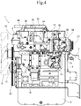
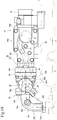
- the fresh air taken into the fresh air inlet flows in the front-rear direction and then in the up-down direction while curving in an L-shape
- the EGR gas taken into the EGR gas inlet flows obliquely upward and mixed in the mixing chamber. Therefore, the EGR gas flows in toward a flow of the fresh air, which facilitates mixing of the EGR gas with the fresh air.
- the mixed gas of the fresh air and the EGR gas flows in the up-down direction and then in the left-right direction while curving in an L-shape, to flow into the intake manifold through the intake outlet.
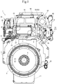
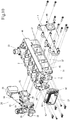
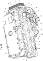
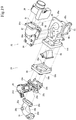
- an intake manifold 3 and an exhaust manifold 4 are disposed in one side portion and the other side portion of the diesel engine 1 parallel to the crankshaft 5.
- the intake manifold 3 provided on a right surface of a cylinder head 2 is formed integrally with the cylinder head 2.
- the exhaust manifold 4 is provided on a left surface of the cylinder head 2.
- the cylinder head 2 is mounted on a cylinder block 6 in which the crankshaft 5 and a piston (not shown) are disposed.
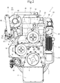
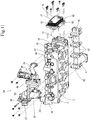
- an outlet opening of the collector 25 of the EGR device 24 is coupled to an inlet opening of the intake manifold 3 provided on the right surface of the cylinder head 2.
- the collector 25 of the EGR device 24 is coupled to the air cleaner via an intercooler (not shown) and the two-stage turbocharger 30, as will be described later.
- An intake outlet 83 of the collector 25 of the EGR device 24 is coupled to the intake inlet 40 of the intake manifold 3 which protrudes from the right surface of the cylinder head 2, and the EGR device 24 is fixed to the right lateral side of the cylinder head 2.
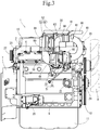
- a direction in which the mixed gas is emitted intersects not only the directions in which the fresh air and the EGR gas are taken in but also the directions in which the fresh air and the EGR gas flow within the collector 25. Consequently, a distribution of mixture of the EGR gas with the fresh air can be made uniformed.
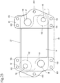
- the right flange portion 93 has the through holes 100 disposed below the coolant inlet 95, above the EGR gas outlet 97, and to the right of a portion between the coolant inlet 95 and the EGR gas outlet 97, a sealability of the coolant inlet 95 and the EGR gas outlet 97 can be exerted when the right flange portion 93 is fastened to the coupling base 34 of the cylinder head 2 with bolts.
Claims (10)
- Motorvorrichtung (1), die umfasst: einen Abgaskrümmer (4), der auf einer der linken und der rechten Seite eines Zylinderkopfs (2) angeordnet ist, und einen Ansaugkrümmer (3), der auf der anderen der linken und der rechten Seite des Zylinderkopfs (2) angeordnet ist, wobei die linke und rechte Seite des Zylinderkopfs (2) entgegengesetzte Seitenabschnitte parallel zu einer Kurbelwelle (5) sind; eine AGR-Vorrichtung (24), die dazu konfiguriert ist, einen Teil des Abgases, das aus dem Abgaskrümmer (4) ausgestoßen wird, als AGR-Gas zu dem Ansaugkrümmer (3) umzuwälzen; und einen AGR-Kühler (27), der dazu konfiguriert ist, das AGR-Gas zu kühlen und das AGR-Gas zu der AGR-Vorrichtung (24) zuzuführen, wobei:
der AGR-Kühler (27) an einer Vorderseite der Motorvorrichtung (1) liegt und einen Wärmetauscher (91), in dem Kühlmittelkanäle und AGR-Gasfluidkanäle abwechselnd gestapelt sind, und zwei Flanschabschnitte (92, 93) beinhaltet, die ein Paar aus linkem und rechtem Flanschabschnitt (92, 93) bilden, die jeweils an einem linken und einem rechten Endabschnitt einer Seitenoberfläche des Wärmetauschers (91) bereitgestellt sind; ein Einlass (95) eines Kühlmittels und ein Auslass des AGR-Gases (97) an einem des linken und des rechten Flanschabschnitts (92, 93) bereitgestellt sind; ein Auslass des Kühlmittels (94) und ein Einlass des AGR-Gases (96) an dem anderen des linken und des rechten Flanschabschnitts (92, 93) bereitgestellt sind; der linke und der rechte Flanschabschnitt (92, 93) mit einer der vorderen und der hinteren Seite des Zylinderkopfs (2) verbunden sind, wobei die vordere und die hintere Seite zu der Kurbelwelle senkrecht sind; und die Flanschabschnitte (92, 93) als separate Elemente konfiguriert sind. - Motorvorrichtung (1) nach Anspruch 1, wobei zwischen dem Wärmetauscher (91) in dem AGR-Kühler (27) und dem Zylinderkopf (2) ein Raum gebildet ist.
- Motorvorrichtung (1) nach Anspruch 1, wobei
der Einlass (95) des Kühlmittels und der Auslass des AGR-Gases (97) in dem Flanschabschnitt (93) übereinander angeordnet sind, und der Auslass des Kühlmittels (94) und der Einlass des AGR-Gases (96) in dem Flanschabschnitt (92) übereinander angeordnet sind; und der Einlass (95) und des Kühlmittels und der Einlass des AGR-Gases (96) auf der gleichen Höhe angeordnet sind, und der Auslass des Kühlmittels (94) und der Auslass des AGR-Gases (97) auf der gleichen Höhe angeordnet sind, wobei der Zylinderkopf (2) oberhalb der Kurbelwelle angeordnet ist. - Motorvorrichtung (1) nach Anspruch 3, wobei der Zylinderkopf (2) beinhaltet: einen stromaufwärtigen AGR-Kanal (31), der die Seite, an der der Abgaskrümmer (4) angeordnet ist, mit der Seite verbindet, an der der AGR-Kühler (27) angeordnet ist; einen stromabwärtigen AGR-Kanal (32), der die Seite, an der der Ansaugkrümmer (3) angeordnet ist, mit der Seite verbindet, an der der AGR-Kühler (27) angeordnet ist; einen stromaufwärtigen Kühlmittelkanal (39), der den Einlass (95) des Kühlmittels verbindet; und einen stromabwärtigen Kühlmittelkanal (38), der den Auslass des Kühlmittels (94), den stromabwärtigen Kühlmittelkanal (38) und den stromaufwärtige AGR-Kanal (31), der an einer Seite des anderen der linken und des rechten Flanschabschnitts (92, 93) des AGR-Kühlers bereitgestellt ist, verbindet, wobei der stromaufwärtige Kühlmittelkanal (39) und der stromabwärtige AGR-Kanal (32) an einer Seite des linken und des rechten Flanschabschnitts (92, 93) des AGR-Kühlers bereitgestellt sind, wobei die linke und die rechte Seite des Zylinderkopfs (2) entgegengesetzte Seitenabschnitte parallel zu einer Kurbelwelle (5) sind.
- Motorvorrichtung (1) nach Anspruch 1, wobei eine plattenförmige Dichtung (98) zwischen dem Zylinderkopf (2) und den Flanschabschnitten derart zwischengefügt ist, dass sie sich über den linken und den rechten Flanschabschnitt (92, 93) erstreckt, ein ringförmiges Dichtungselement (99) in jeden des Auslasses (94) und des Einlasses (95) des Kühlmittels in dem Zylinderkopf (2) eingebettet ist, die jeweils den Einlass (95) und den Auslass (94) des Kühlmittels in den Flanschabschnitten verbinden, und das Dichtungselement von den Flanschabschnitten umgeben ist.
- Motorvorrichtung (1) nach Anspruch 1, wobei die AGR-Vorrichtung (24) ein Hauptkörpergehäuse (25) beinhaltet, das dazu konfiguriert ist, die Frischluft mit dem AGR-Gas zu mischen und das gemischte Gas zu dem Ansaugkrümmer (3) zuzuführen, das Hauptkörpergehäuse (25) derart konfiguriert ist, dass eine Frischluftströmungsrichtung und eine AGR-Gasströmungsrichtung darin einander senkrecht oder mit einem stumpfen Winkel kreuzen, und dass eine Richtung, in der ein gemischtes Gas aus dem AGR-Gas und der Frischluft in den Ansaugkrümmer (3) genommen wird, jede der Frischluftströmungsrichtung und der AGR-Gasströmungsrichtung schneidet.
- Motorvorrichtung (1) nach Anspruch 6, wobei:
ein Frischlufteinlass (63), zu dem Frischluft zugeführt wird, an einer der Vorder- und der Rückseite des Hauptkörpergehäuses (25) geöffnet ist, während ein AGR-Gaseinlass (96), zu dem das AGR-Gas zugeführt wird, an der anderen der Vorder- und der Rückseite des Hauptkörpergehäuses (25) geöffnet ist, ein Ansaugauslass (83), der mit dem Ansaugkrümmer (3) in Verbindung steht, an einer der linken und der rechten Seite des Hauptkörpergehäuses (25) geöffnet ist, der Ansaugauslass (83) und der AGR-Gaseinlass (96) auf der gleichen Höhe angeordnet sind und der Frischlufteinlass (63) und der AGR-Gaseinlass (96) auf unterschiedlichen Höhen angeordnet sind. - Motorvorrichtung (1) nach Anspruch 7, wobei das Hauptkörpergehäuse (25) ein erstes Gehäuse (84) mit dem Frischlufteinlass (63) und ein zweites Gehäuse (85) mit dem Ansaugauslass (83) und dem AGR-Gaseinlass (96) beinhaltet, die miteinander gekoppelt sind.
- Motorvorrichtung (1) nach Anspruch 8, wobei:das erste Gehäuse (84) darin mit einem ersten AGR-Gasfluidkanal, der einen Teil des AGR-Gaskanals bildet, in dem das AGR-Gas strömt, und einer Mischkammer (87) versehen ist, in der Frischluft und das AGR-Gas gemischt werden; unddas zweite Gehäuse (85) mit einem zweiten AGR-Gasfluidkanal, durch den der erste AGR-Gasfluidkanal mit dem AGR-Gaseinlass (96) in Verbindung steht, und einem Mischgasfluidkanal versehen ist, durch den Mischgas, das durch Mischen der Frischluft mit dem AGR-Gas erhalten wird, von der Mischkammer (87) zu dem Ansaugkrümmer (3) zugeführt wird.
- Motorvorrichtung (1) nach Anspruch 9, wobei:der erste AGR-Gasfluidkanal mit einem Versatz zu einer Seitenoberfläche der Mischkammer (87) einer Seitenoberfläche davon entgegengesetzt, die den Ansaugauslass (83) relativ zu einer Mittelachse der Mischkammer (87) aufweist, gekoppelt ist, undder erste AGR-Gasfluidkanal und der zweite AGR-Gasfluidkanal miteinander derart in Verbindung stehen, dass der AGR-Gasfluidkanal in einer spiralförmigen Weise gebildet ist.
Applications Claiming Priority (3)
| Application Number | Priority Date | Filing Date | Title |
|---|---|---|---|
| JP2016066824A JP6442429B2 (ja) | 2016-03-29 | 2016-03-29 | エンジン装置 |
| JP2016066823A JP2017180227A (ja) | 2016-03-29 | 2016-03-29 | エンジン装置 |
| PCT/JP2017/010037 WO2017169700A1 (ja) | 2016-03-29 | 2017-03-13 | エンジン装置 |
Publications (3)
| Publication Number | Publication Date |
|---|---|
| EP3438438A1 EP3438438A1 (de) | 2019-02-06 |
| EP3438438A4 EP3438438A4 (de) | 2019-04-17 |
| EP3438438B1 true EP3438438B1 (de) | 2021-12-29 |
Family
ID=59964257
Family Applications (1)
| Application Number | Title | Priority Date | Filing Date |
|---|---|---|---|
| EP17774244.2A Active EP3438438B1 (de) | 2016-03-29 | 2017-03-13 | Motorvorrichtung |
Country Status (5)
| Country | Link |
|---|---|
| US (2) | US10626833B2 (de) |
| EP (1) | EP3438438B1 (de) |
| KR (1) | KR101970930B1 (de) |
| CN (1) | CN108884791B (de) |
| WO (1) | WO2017169700A1 (de) |
Families Citing this family (6)
| Publication number | Priority date | Publication date | Assignee | Title |
|---|---|---|---|---|
| JP6718573B2 (ja) * | 2017-01-30 | 2020-07-08 | ヤンマーパワーテクノロジー株式会社 | エンジン装置 |
| JP6913007B2 (ja) * | 2017-11-16 | 2021-08-04 | 株式会社神戸製鋼所 | 配管部材及び流体輸送装置 |
| JP6871845B2 (ja) * | 2017-12-15 | 2021-05-19 | ヤンマーパワーテクノロジー株式会社 | シリンダヘッド及びエンジン |
| JP7196755B2 (ja) | 2019-04-26 | 2022-12-27 | スズキ株式会社 | 車両用エンジン |
| WO2020162640A1 (ja) | 2020-02-17 | 2020-08-13 | 株式会社小松製作所 | シリンダヘッド及びエンジン |
| CN112282982B (zh) * | 2020-10-29 | 2022-08-19 | 东风商用车有限公司 | 天然气发动机用文丘里式混合器 |
Family Cites Families (41)
| Publication number | Priority date | Publication date | Assignee | Title |
|---|---|---|---|---|
| US4267812A (en) * | 1979-10-09 | 1981-05-19 | Ford Motor Company | Engine EGR cooler |
| US4258687A (en) * | 1979-10-09 | 1981-03-31 | Ford Motor Company | Engine with integral mounted EGR cooler |
| JP2000008969A (ja) | 1998-06-22 | 2000-01-11 | Nissan Diesel Motor Co Ltd | Egr装置 |
| JP4071370B2 (ja) | 1998-09-10 | 2008-04-02 | ヤマハ発動機株式会社 | 筒内噴射式エンジン用egr弁装置 |
| JP3852255B2 (ja) | 1999-11-10 | 2006-11-29 | いすゞ自動車株式会社 | Egr及びオイルの冷却装置 |
| DE10119484B4 (de) | 2001-04-20 | 2018-01-04 | Bayerische Motoren Werke Aktiengesellschaft | Flüssigkeitsgekühlte Brennkraftmaschine mit einem Abgasrückführsystem |
| DE10153033B4 (de) * | 2001-10-26 | 2018-03-01 | Bayerische Motoren Werke Aktiengesellschaft | Abgas-Rückführ-Wärmetauscher für eine flüssigkeitsgekühlte Brennkraftmaschine |
| JP2005133981A (ja) * | 2003-10-28 | 2005-05-26 | Mitsubishi Fuso Truck & Bus Corp | 排気熱交換器 |
| DE102005031300B4 (de) * | 2005-07-05 | 2021-05-12 | Daimler Ag | Brennkraftmaschine mit Kühlsystem und Abgasrückführsystem |
| JP4484800B2 (ja) | 2005-09-28 | 2010-06-16 | 株式会社クボタ | エンジン |
| JP2009512832A (ja) * | 2005-10-20 | 2009-03-26 | ベール ゲーエムベーハー ウント コー カーゲー | 熱交換器 |
| JP2007292012A (ja) * | 2006-04-27 | 2007-11-08 | Nissan Motor Co Ltd | 内燃機関の排気還流装置 |
| KR101298382B1 (ko) * | 2006-07-03 | 2013-08-20 | 모다인 매뉴팩츄어링 컴파니 | Egr 쿨러 |
| EP2077387B1 (de) | 2008-01-07 | 2011-07-27 | Ford Global Technologies, LLC | Verfahren zur Kühlung eines rückzuführenden Abgasstroms einer Brennkraftmaschine |
| US20100224173A1 (en) * | 2009-03-09 | 2010-09-09 | Herve Palanchon | Heat Exchanger with Cast Housing and Method of Making Same |
| CN201420627Y (zh) * | 2009-04-29 | 2010-03-10 | 临海市邦得利汽车环保技术有限公司 | 柴油机egr冷却器 |
| JP5051212B2 (ja) * | 2009-12-18 | 2012-10-17 | トヨタ自動車株式会社 | 排気冷却器および内燃機関の排気再循環装置 |
| JP5387612B2 (ja) * | 2010-06-25 | 2014-01-15 | マツダ株式会社 | エンジンの排気還流装置 |
| US10016856B2 (en) * | 2010-12-16 | 2018-07-10 | Eugene Neal | Method of rebuilding an EGR cooler |
| JP5578367B2 (ja) * | 2011-01-27 | 2014-08-27 | アイシン精機株式会社 | エンジンの吸気装置 |
| GB2487591B (en) * | 2011-01-28 | 2016-07-20 | Gm Global Tech Operations Llc | Internal Combustion Engine Having a Cooler Located in an Intake Manifold |
| WO2012107951A1 (ja) * | 2011-02-08 | 2012-08-16 | トヨタ自動車株式会社 | 内燃機関の排気循環装置 |
| JP2012172534A (ja) * | 2011-02-17 | 2012-09-10 | Tokyo Roki Co Ltd | Egrクーラ |
| JP5881983B2 (ja) * | 2011-07-07 | 2016-03-09 | ヤンマー株式会社 | エンジンの排気再循環装置 |
| JP5904108B2 (ja) * | 2011-12-19 | 2016-04-13 | 株式会社デンソー | 排気熱交換装置 |
| EP2806137B1 (de) * | 2012-01-20 | 2018-06-06 | Yanmar Co., Ltd. | Schiffsmotor |
| FR2986745A1 (fr) * | 2012-02-15 | 2013-08-16 | Peugeot Citroen Automobiles Sa | Support moteur integrant un conduit de recirculation des gaz d'echappement, culasse adaptee et vehicule correspondant |
| JP2013177818A (ja) * | 2012-02-28 | 2013-09-09 | Daihatsu Motor Co Ltd | Egr通路構造 |
| CN102619648B (zh) * | 2012-03-21 | 2014-06-04 | 浙江银轮机械股份有限公司 | 一种具有隔热功能的板翅式egr冷却器 |
| US20150136369A1 (en) * | 2012-06-08 | 2015-05-21 | International Engine Intellectual Property Company Llc | Egr cooler header casting |
| JP6140541B2 (ja) * | 2013-06-17 | 2017-05-31 | マルヤス工業株式会社 | 多管式熱交換器 |
| US20150021004A1 (en) * | 2013-07-18 | 2015-01-22 | International Engine Intellectual Property Company Llc | EGR Cooler |
| KR101490963B1 (ko) * | 2013-12-11 | 2015-02-06 | 현대자동차 주식회사 | 터보차저를 갖는 엔진시스템 |
| KR101583889B1 (ko) * | 2013-12-20 | 2016-01-21 | 현대자동차주식회사 | 차량의 오일온도 조절장치 및 그 제어방법 |
| US9243547B2 (en) * | 2014-02-13 | 2016-01-26 | Ford Global Technologies, Llc | Dual inlet and outlet exhaust gas recirculation cooler for turbocharged engine |
| DE102014004133A1 (de) * | 2014-03-24 | 2015-09-24 | Man Truck & Bus Ag | Homogenisierungsvorrichtung für wenigstens zwei Fluidströme, insbesondere zur homogenen Gas-Luft-Vermischung bei einem Gasmotor |
| DE112015000071T5 (de) * | 2014-04-04 | 2016-02-11 | Suzuki Motor Corporation | Einlassvorrichtung für Motor |
| US9062634B1 (en) * | 2014-04-08 | 2015-06-23 | Internaitonal Engine Intellectual Property Company, Llc | EGR cooler |
| DE102015003908A1 (de) * | 2015-03-27 | 2016-09-29 | Deutz Aktiengesellschaft | Brennkraftmaschine mit Abgasrückführung und/oder wassergekühltem Ladeluftkühler |
| US10330054B2 (en) * | 2016-03-24 | 2019-06-25 | Ford Global Technologies, Llc | Systems and method for an exhaust gas recirculation cooler coupled to a cylinder head |
| JP6473096B2 (ja) * | 2016-03-29 | 2019-02-20 | ヤンマー株式会社 | エンジン装置 |
-
2017
- 2017-03-13 KR KR1020187011574A patent/KR101970930B1/ko active IP Right Grant
- 2017-03-13 US US16/088,796 patent/US10626833B2/en active Active
- 2017-03-13 EP EP17774244.2A patent/EP3438438B1/de active Active
- 2017-03-13 WO PCT/JP2017/010037 patent/WO2017169700A1/ja active Application Filing
- 2017-03-13 CN CN201780003149.7A patent/CN108884791B/zh active Active
-
2020
- 2020-04-14 US US16/848,096 patent/US11035327B2/en active Active
Non-Patent Citations (1)
| Title |
|---|
| None * |
Also Published As
| Publication number | Publication date |
|---|---|
| EP3438438A4 (de) | 2019-04-17 |
| US11035327B2 (en) | 2021-06-15 |
| KR20180059847A (ko) | 2018-06-05 |
| US20190078540A1 (en) | 2019-03-14 |
| WO2017169700A1 (ja) | 2017-10-05 |
| CN108884791A (zh) | 2018-11-23 |
| CN108884791B (zh) | 2021-11-16 |
| EP3438438A1 (de) | 2019-02-06 |
| KR101970930B1 (ko) | 2019-08-13 |
| US10626833B2 (en) | 2020-04-21 |
| US20200240374A1 (en) | 2020-07-30 |
Similar Documents
| Publication | Publication Date | Title |
|---|---|---|
| EP3438433B1 (de) | Motorvorrichtung | |
| EP3438438B1 (de) | Motorvorrichtung | |
| US20210231045A1 (en) | Engine Device | |
| US20210310404A1 (en) | Engine Device | |
| JP7270087B2 (ja) | エンジン装置 | |
| JP2017180227A (ja) | エンジン装置 | |
| JP6442429B2 (ja) | エンジン装置 | |
| JP7415068B2 (ja) | エンジン装置 | |
| JP7035146B2 (ja) | エンジン装置 |
Legal Events
| Date | Code | Title | Description |
|---|---|---|---|
| STAA | Information on the status of an ep patent application or granted ep patent |
Free format text: STATUS: THE INTERNATIONAL PUBLICATION HAS BEEN MADE |
|
| PUAI | Public reference made under article 153(3) epc to a published international application that has entered the european phase |
Free format text: ORIGINAL CODE: 0009012 |
|
| STAA | Information on the status of an ep patent application or granted ep patent |
Free format text: STATUS: REQUEST FOR EXAMINATION WAS MADE |
|
| 17P | Request for examination filed |
Effective date: 20181025 |
|
| AK | Designated contracting states |
Kind code of ref document: A1 Designated state(s): AL AT BE BG CH CY CZ DE DK EE ES FI FR GB GR HR HU IE IS IT LI LT LU LV MC MK MT NL NO PL PT RO RS SE SI SK SM TR |
|
| AX | Request for extension of the european patent |
Extension state: BA ME |
|
| A4 | Supplementary search report drawn up and despatched |
Effective date: 20190319 |
|
| RIC1 | Information provided on ipc code assigned before grant |
Ipc: F02M 26/32 20160101ALI20190313BHEP Ipc: F02M 35/104 20060101ALI20190313BHEP Ipc: F02M 26/41 20160101ALI20190313BHEP Ipc: F02M 26/30 20160101ALI20190313BHEP Ipc: F02M 35/10 20060101ALI20190313BHEP Ipc: F02M 26/68 20160101ALI20190313BHEP Ipc: F02B 67/00 20060101ALI20190313BHEP Ipc: F02M 26/19 20160101AFI20190313BHEP Ipc: F02M 26/72 20160101ALI20190313BHEP Ipc: F02F 1/24 20060101ALI20190313BHEP Ipc: F02M 26/21 20160101ALI20190313BHEP |
|
| DAV | Request for validation of the european patent (deleted) | ||
| DAX | Request for extension of the european patent (deleted) | ||
| STAA | Information on the status of an ep patent application or granted ep patent |
Free format text: STATUS: EXAMINATION IS IN PROGRESS |
|
| 17Q | First examination report despatched |
Effective date: 20191212 |
|
| RAP1 | Party data changed (applicant data changed or rights of an application transferred) |
Owner name: YANMAR POWER TECHNOLOGY CO., LTD. |
|
| STAA | Information on the status of an ep patent application or granted ep patent |
Free format text: STATUS: EXAMINATION IS IN PROGRESS |
|
| GRAP | Despatch of communication of intention to grant a patent |
Free format text: ORIGINAL CODE: EPIDOSNIGR1 |
|
| STAA | Information on the status of an ep patent application or granted ep patent |
Free format text: STATUS: GRANT OF PATENT IS INTENDED |
|
| INTG | Intention to grant announced |
Effective date: 20210720 |
|
| GRAS | Grant fee paid |
Free format text: ORIGINAL CODE: EPIDOSNIGR3 |
|
| GRAA | (expected) grant |
Free format text: ORIGINAL CODE: 0009210 |
|
| STAA | Information on the status of an ep patent application or granted ep patent |
Free format text: STATUS: THE PATENT HAS BEEN GRANTED |
|
| AK | Designated contracting states |
Kind code of ref document: B1 Designated state(s): AL AT BE BG CH CY CZ DE DK EE ES FI FR GB GR HR HU IE IS IT LI LT LU LV MC MK MT NL NO PL PT RO RS SE SI SK SM TR |
|
| REG | Reference to a national code |
Ref country code: GB Ref legal event code: FG4D |
|
| REG | Reference to a national code |
Ref country code: CH Ref legal event code: EP |
|
| REG | Reference to a national code |
Ref country code: AT Ref legal event code: REF Ref document number: 1458863 Country of ref document: AT Kind code of ref document: T Effective date: 20220115 |
|
| REG | Reference to a national code |
Ref country code: IE Ref legal event code: FG4D |
|
| REG | Reference to a national code |
Ref country code: DE Ref legal event code: R096 Ref document number: 602017051606 Country of ref document: DE |
|
| REG | Reference to a national code |
Ref country code: LT Ref legal event code: MG9D |
|
| PG25 | Lapsed in a contracting state [announced via postgrant information from national office to epo] |
Ref country code: RS Free format text: LAPSE BECAUSE OF FAILURE TO SUBMIT A TRANSLATION OF THE DESCRIPTION OR TO PAY THE FEE WITHIN THE PRESCRIBED TIME-LIMIT Effective date: 20211229 Ref country code: LT Free format text: LAPSE BECAUSE OF FAILURE TO SUBMIT A TRANSLATION OF THE DESCRIPTION OR TO PAY THE FEE WITHIN THE PRESCRIBED TIME-LIMIT Effective date: 20211229 Ref country code: FI Free format text: LAPSE BECAUSE OF FAILURE TO SUBMIT A TRANSLATION OF THE DESCRIPTION OR TO PAY THE FEE WITHIN THE PRESCRIBED TIME-LIMIT Effective date: 20211229 Ref country code: BG Free format text: LAPSE BECAUSE OF FAILURE TO SUBMIT A TRANSLATION OF THE DESCRIPTION OR TO PAY THE FEE WITHIN THE PRESCRIBED TIME-LIMIT Effective date: 20220329 |
|
| REG | Reference to a national code |
Ref country code: NL Ref legal event code: MP Effective date: 20211229 |
|
| REG | Reference to a national code |
Ref country code: AT Ref legal event code: MK05 Ref document number: 1458863 Country of ref document: AT Kind code of ref document: T Effective date: 20211229 |
|
| PG25 | Lapsed in a contracting state [announced via postgrant information from national office to epo] |
Ref country code: SE Free format text: LAPSE BECAUSE OF FAILURE TO SUBMIT A TRANSLATION OF THE DESCRIPTION OR TO PAY THE FEE WITHIN THE PRESCRIBED TIME-LIMIT Effective date: 20211229 Ref country code: NO Free format text: LAPSE BECAUSE OF FAILURE TO SUBMIT A TRANSLATION OF THE DESCRIPTION OR TO PAY THE FEE WITHIN THE PRESCRIBED TIME-LIMIT Effective date: 20220329 Ref country code: LV Free format text: LAPSE BECAUSE OF FAILURE TO SUBMIT A TRANSLATION OF THE DESCRIPTION OR TO PAY THE FEE WITHIN THE PRESCRIBED TIME-LIMIT Effective date: 20211229 Ref country code: HR Free format text: LAPSE BECAUSE OF FAILURE TO SUBMIT A TRANSLATION OF THE DESCRIPTION OR TO PAY THE FEE WITHIN THE PRESCRIBED TIME-LIMIT Effective date: 20211229 Ref country code: GR Free format text: LAPSE BECAUSE OF FAILURE TO SUBMIT A TRANSLATION OF THE DESCRIPTION OR TO PAY THE FEE WITHIN THE PRESCRIBED TIME-LIMIT Effective date: 20220330 |
|
| PG25 | Lapsed in a contracting state [announced via postgrant information from national office to epo] |
Ref country code: NL Free format text: LAPSE BECAUSE OF FAILURE TO SUBMIT A TRANSLATION OF THE DESCRIPTION OR TO PAY THE FEE WITHIN THE PRESCRIBED TIME-LIMIT Effective date: 20211229 |
|
| PG25 | Lapsed in a contracting state [announced via postgrant information from national office to epo] |
Ref country code: SM Free format text: LAPSE BECAUSE OF FAILURE TO SUBMIT A TRANSLATION OF THE DESCRIPTION OR TO PAY THE FEE WITHIN THE PRESCRIBED TIME-LIMIT Effective date: 20211229 Ref country code: SK Free format text: LAPSE BECAUSE OF FAILURE TO SUBMIT A TRANSLATION OF THE DESCRIPTION OR TO PAY THE FEE WITHIN THE PRESCRIBED TIME-LIMIT Effective date: 20211229 Ref country code: RO Free format text: LAPSE BECAUSE OF FAILURE TO SUBMIT A TRANSLATION OF THE DESCRIPTION OR TO PAY THE FEE WITHIN THE PRESCRIBED TIME-LIMIT Effective date: 20211229 Ref country code: PT Free format text: LAPSE BECAUSE OF FAILURE TO SUBMIT A TRANSLATION OF THE DESCRIPTION OR TO PAY THE FEE WITHIN THE PRESCRIBED TIME-LIMIT Effective date: 20220429 Ref country code: ES Free format text: LAPSE BECAUSE OF FAILURE TO SUBMIT A TRANSLATION OF THE DESCRIPTION OR TO PAY THE FEE WITHIN THE PRESCRIBED TIME-LIMIT Effective date: 20211229 Ref country code: EE Free format text: LAPSE BECAUSE OF FAILURE TO SUBMIT A TRANSLATION OF THE DESCRIPTION OR TO PAY THE FEE WITHIN THE PRESCRIBED TIME-LIMIT Effective date: 20211229 Ref country code: CZ Free format text: LAPSE BECAUSE OF FAILURE TO SUBMIT A TRANSLATION OF THE DESCRIPTION OR TO PAY THE FEE WITHIN THE PRESCRIBED TIME-LIMIT Effective date: 20211229 |
|
| PG25 | Lapsed in a contracting state [announced via postgrant information from national office to epo] |
Ref country code: PL Free format text: LAPSE BECAUSE OF FAILURE TO SUBMIT A TRANSLATION OF THE DESCRIPTION OR TO PAY THE FEE WITHIN THE PRESCRIBED TIME-LIMIT Effective date: 20211229 Ref country code: AT Free format text: LAPSE BECAUSE OF FAILURE TO SUBMIT A TRANSLATION OF THE DESCRIPTION OR TO PAY THE FEE WITHIN THE PRESCRIBED TIME-LIMIT Effective date: 20211229 |
|
| PG25 | Lapsed in a contracting state [announced via postgrant information from national office to epo] |
Ref country code: IS Free format text: LAPSE BECAUSE OF FAILURE TO SUBMIT A TRANSLATION OF THE DESCRIPTION OR TO PAY THE FEE WITHIN THE PRESCRIBED TIME-LIMIT Effective date: 20220429 |
|
| REG | Reference to a national code |
Ref country code: DE Ref legal event code: R097 Ref document number: 602017051606 Country of ref document: DE |
|
| PG25 | Lapsed in a contracting state [announced via postgrant information from national office to epo] |
Ref country code: MC Free format text: LAPSE BECAUSE OF FAILURE TO SUBMIT A TRANSLATION OF THE DESCRIPTION OR TO PAY THE FEE WITHIN THE PRESCRIBED TIME-LIMIT Effective date: 20211229 Ref country code: DK Free format text: LAPSE BECAUSE OF FAILURE TO SUBMIT A TRANSLATION OF THE DESCRIPTION OR TO PAY THE FEE WITHIN THE PRESCRIBED TIME-LIMIT Effective date: 20211229 Ref country code: AL Free format text: LAPSE BECAUSE OF FAILURE TO SUBMIT A TRANSLATION OF THE DESCRIPTION OR TO PAY THE FEE WITHIN THE PRESCRIBED TIME-LIMIT Effective date: 20211229 |
|
| REG | Reference to a national code |
Ref country code: CH Ref legal event code: PL |
|
| PLBE | No opposition filed within time limit |
Free format text: ORIGINAL CODE: 0009261 |
|
| STAA | Information on the status of an ep patent application or granted ep patent |
Free format text: STATUS: NO OPPOSITION FILED WITHIN TIME LIMIT |
|
| 26N | No opposition filed |
Effective date: 20220930 |
|
| REG | Reference to a national code |
Ref country code: BE Ref legal event code: MM Effective date: 20220331 |
|
| PG25 | Lapsed in a contracting state [announced via postgrant information from national office to epo] |
Ref country code: LU Free format text: LAPSE BECAUSE OF NON-PAYMENT OF DUE FEES Effective date: 20220313 Ref country code: LI Free format text: LAPSE BECAUSE OF NON-PAYMENT OF DUE FEES Effective date: 20220331 Ref country code: IE Free format text: LAPSE BECAUSE OF NON-PAYMENT OF DUE FEES Effective date: 20220313 Ref country code: CH Free format text: LAPSE BECAUSE OF NON-PAYMENT OF DUE FEES Effective date: 20220331 |
|
| PG25 | Lapsed in a contracting state [announced via postgrant information from national office to epo] |
Ref country code: SI Free format text: LAPSE BECAUSE OF FAILURE TO SUBMIT A TRANSLATION OF THE DESCRIPTION OR TO PAY THE FEE WITHIN THE PRESCRIBED TIME-LIMIT Effective date: 20211229 Ref country code: BE Free format text: LAPSE BECAUSE OF NON-PAYMENT OF DUE FEES Effective date: 20220331 |
|
| PGFP | Annual fee paid to national office [announced via postgrant information from national office to epo] |
Ref country code: FR Payment date: 20230327 Year of fee payment: 7 |
|
| PG25 | Lapsed in a contracting state [announced via postgrant information from national office to epo] |
Ref country code: IT Free format text: LAPSE BECAUSE OF FAILURE TO SUBMIT A TRANSLATION OF THE DESCRIPTION OR TO PAY THE FEE WITHIN THE PRESCRIBED TIME-LIMIT Effective date: 20211229 |
|
| PGFP | Annual fee paid to national office [announced via postgrant information from national office to epo] |
Ref country code: GB Payment date: 20230322 Year of fee payment: 7 Ref country code: DE Payment date: 20230321 Year of fee payment: 7 |
|
| PG25 | Lapsed in a contracting state [announced via postgrant information from national office to epo] |
Ref country code: HU Free format text: LAPSE BECAUSE OF FAILURE TO SUBMIT A TRANSLATION OF THE DESCRIPTION OR TO PAY THE FEE WITHIN THE PRESCRIBED TIME-LIMIT; INVALID AB INITIO Effective date: 20170313 |
|
| PG25 | Lapsed in a contracting state [announced via postgrant information from national office to epo] |
Ref country code: MK Free format text: LAPSE BECAUSE OF FAILURE TO SUBMIT A TRANSLATION OF THE DESCRIPTION OR TO PAY THE FEE WITHIN THE PRESCRIBED TIME-LIMIT Effective date: 20211229 Ref country code: CY Free format text: LAPSE BECAUSE OF FAILURE TO SUBMIT A TRANSLATION OF THE DESCRIPTION OR TO PAY THE FEE WITHIN THE PRESCRIBED TIME-LIMIT Effective date: 20211229 |
|
| PGFP | Annual fee paid to national office [announced via postgrant information from national office to epo] |
Ref country code: DE Payment date: 20240320 Year of fee payment: 8 Ref country code: GB Payment date: 20240320 Year of fee payment: 8 |