EP3433093B1 - Thermisch gedämmte mediumrohre mit hfo-haltigem zellgas - Google Patents
Thermisch gedämmte mediumrohre mit hfo-haltigem zellgas Download PDFInfo
- Publication number
- EP3433093B1 EP3433093B1 EP17742968.5A EP17742968A EP3433093B1 EP 3433093 B1 EP3433093 B1 EP 3433093B1 EP 17742968 A EP17742968 A EP 17742968A EP 3433093 B1 EP3433093 B1 EP 3433093B1
- Authority
- EP
- European Patent Office
- Prior art keywords
- vol
- thermal insulation
- hfo
- pipe
- barrier
- Prior art date
- Legal status (The legal status is an assumption and is not a legal conclusion. Google has not performed a legal analysis and makes no representation as to the accuracy of the status listed.)
- Revoked
Links
Images

Classifications
-
- F—MECHANICAL ENGINEERING; LIGHTING; HEATING; WEAPONS; BLASTING
- F16—ENGINEERING ELEMENTS AND UNITS; GENERAL MEASURES FOR PRODUCING AND MAINTAINING EFFECTIVE FUNCTIONING OF MACHINES OR INSTALLATIONS; THERMAL INSULATION IN GENERAL
- F16L—PIPES; JOINTS OR FITTINGS FOR PIPES; SUPPORTS FOR PIPES, CABLES OR PROTECTIVE TUBING; MEANS FOR THERMAL INSULATION IN GENERAL
- F16L59/00—Thermal insulation in general
- F16L59/14—Arrangements for the insulation of pipes or pipe systems
- F16L59/143—Pre-insulated pipes
-
- B—PERFORMING OPERATIONS; TRANSPORTING
- B29—WORKING OF PLASTICS; WORKING OF SUBSTANCES IN A PLASTIC STATE IN GENERAL
- B29C—SHAPING OR JOINING OF PLASTICS; SHAPING OF MATERIAL IN A PLASTIC STATE, NOT OTHERWISE PROVIDED FOR; AFTER-TREATMENT OF THE SHAPED PRODUCTS, e.g. REPAIRING
- B29C44/00—Shaping by internal pressure generated in the material, e.g. swelling or foaming ; Producing porous or cellular expanded plastics articles
- B29C44/02—Shaping by internal pressure generated in the material, e.g. swelling or foaming ; Producing porous or cellular expanded plastics articles for articles of definite length, i.e. discrete articles
- B29C44/04—Shaping by internal pressure generated in the material, e.g. swelling or foaming ; Producing porous or cellular expanded plastics articles for articles of definite length, i.e. discrete articles consisting of at least two parts of chemically or physically different materials, e.g. having different densities
-
- B—PERFORMING OPERATIONS; TRANSPORTING
- B29—WORKING OF PLASTICS; WORKING OF SUBSTANCES IN A PLASTIC STATE IN GENERAL
- B29C—SHAPING OR JOINING OF PLASTICS; SHAPING OF MATERIAL IN A PLASTIC STATE, NOT OTHERWISE PROVIDED FOR; AFTER-TREATMENT OF THE SHAPED PRODUCTS, e.g. REPAIRING
- B29C44/00—Shaping by internal pressure generated in the material, e.g. swelling or foaming ; Producing porous or cellular expanded plastics articles
- B29C44/02—Shaping by internal pressure generated in the material, e.g. swelling or foaming ; Producing porous or cellular expanded plastics articles for articles of definite length, i.e. discrete articles
- B29C44/12—Incorporating or moulding on preformed parts, e.g. inserts or reinforcements
-
- B—PERFORMING OPERATIONS; TRANSPORTING
- B29—WORKING OF PLASTICS; WORKING OF SUBSTANCES IN A PLASTIC STATE IN GENERAL
- B29C—SHAPING OR JOINING OF PLASTICS; SHAPING OF MATERIAL IN A PLASTIC STATE, NOT OTHERWISE PROVIDED FOR; AFTER-TREATMENT OF THE SHAPED PRODUCTS, e.g. REPAIRING
- B29C44/00—Shaping by internal pressure generated in the material, e.g. swelling or foaming ; Producing porous or cellular expanded plastics articles
- B29C44/20—Shaping by internal pressure generated in the material, e.g. swelling or foaming ; Producing porous or cellular expanded plastics articles for articles of indefinite length
-
- B—PERFORMING OPERATIONS; TRANSPORTING
- B29—WORKING OF PLASTICS; WORKING OF SUBSTANCES IN A PLASTIC STATE IN GENERAL
- B29D—PRODUCING PARTICULAR ARTICLES FROM PLASTICS OR FROM SUBSTANCES IN A PLASTIC STATE
- B29D23/00—Producing tubular articles
- B29D23/001—Pipes; Pipe joints
-
- B—PERFORMING OPERATIONS; TRANSPORTING
- B32—LAYERED PRODUCTS
- B32B—LAYERED PRODUCTS, i.e. PRODUCTS BUILT-UP OF STRATA OF FLAT OR NON-FLAT, e.g. CELLULAR OR HONEYCOMB, FORM
- B32B1/00—Layered products having a non-planar shape
- B32B1/08—Tubular products
-
- B—PERFORMING OPERATIONS; TRANSPORTING
- B32—LAYERED PRODUCTS
- B32B—LAYERED PRODUCTS, i.e. PRODUCTS BUILT-UP OF STRATA OF FLAT OR NON-FLAT, e.g. CELLULAR OR HONEYCOMB, FORM
- B32B15/00—Layered products comprising a layer of metal
- B32B15/04—Layered products comprising a layer of metal comprising metal as the main or only constituent of a layer, which is next to another layer of the same or of a different material
- B32B15/046—Layered products comprising a layer of metal comprising metal as the main or only constituent of a layer, which is next to another layer of the same or of a different material of foam
-
- B—PERFORMING OPERATIONS; TRANSPORTING
- B32—LAYERED PRODUCTS
- B32B—LAYERED PRODUCTS, i.e. PRODUCTS BUILT-UP OF STRATA OF FLAT OR NON-FLAT, e.g. CELLULAR OR HONEYCOMB, FORM
- B32B15/00—Layered products comprising a layer of metal
- B32B15/04—Layered products comprising a layer of metal comprising metal as the main or only constituent of a layer, which is next to another layer of the same or of a different material
- B32B15/08—Layered products comprising a layer of metal comprising metal as the main or only constituent of a layer, which is next to another layer of the same or of a different material of synthetic resin
-
- B—PERFORMING OPERATIONS; TRANSPORTING
- B32—LAYERED PRODUCTS
- B32B—LAYERED PRODUCTS, i.e. PRODUCTS BUILT-UP OF STRATA OF FLAT OR NON-FLAT, e.g. CELLULAR OR HONEYCOMB, FORM
- B32B15/00—Layered products comprising a layer of metal
- B32B15/20—Layered products comprising a layer of metal comprising aluminium or copper
-
- B—PERFORMING OPERATIONS; TRANSPORTING
- B32—LAYERED PRODUCTS
- B32B—LAYERED PRODUCTS, i.e. PRODUCTS BUILT-UP OF STRATA OF FLAT OR NON-FLAT, e.g. CELLULAR OR HONEYCOMB, FORM
- B32B27/00—Layered products comprising a layer of synthetic resin
- B32B27/06—Layered products comprising a layer of synthetic resin as the main or only constituent of a layer, which is next to another layer of the same or of a different material
- B32B27/065—Layered products comprising a layer of synthetic resin as the main or only constituent of a layer, which is next to another layer of the same or of a different material of foam
-
- B—PERFORMING OPERATIONS; TRANSPORTING
- B32—LAYERED PRODUCTS
- B32B—LAYERED PRODUCTS, i.e. PRODUCTS BUILT-UP OF STRATA OF FLAT OR NON-FLAT, e.g. CELLULAR OR HONEYCOMB, FORM
- B32B27/00—Layered products comprising a layer of synthetic resin
- B32B27/06—Layered products comprising a layer of synthetic resin as the main or only constituent of a layer, which is next to another layer of the same or of a different material
- B32B27/08—Layered products comprising a layer of synthetic resin as the main or only constituent of a layer, which is next to another layer of the same or of a different material of synthetic resin
-
- B—PERFORMING OPERATIONS; TRANSPORTING
- B32—LAYERED PRODUCTS
- B32B—LAYERED PRODUCTS, i.e. PRODUCTS BUILT-UP OF STRATA OF FLAT OR NON-FLAT, e.g. CELLULAR OR HONEYCOMB, FORM
- B32B27/00—Layered products comprising a layer of synthetic resin
- B32B27/30—Layered products comprising a layer of synthetic resin comprising vinyl (co)polymers; comprising acrylic (co)polymers
- B32B27/306—Layered products comprising a layer of synthetic resin comprising vinyl (co)polymers; comprising acrylic (co)polymers comprising vinyl acetate or vinyl alcohol (co)polymers
-
- B—PERFORMING OPERATIONS; TRANSPORTING
- B32—LAYERED PRODUCTS
- B32B—LAYERED PRODUCTS, i.e. PRODUCTS BUILT-UP OF STRATA OF FLAT OR NON-FLAT, e.g. CELLULAR OR HONEYCOMB, FORM
- B32B27/00—Layered products comprising a layer of synthetic resin
- B32B27/32—Layered products comprising a layer of synthetic resin comprising polyolefins
-
- B—PERFORMING OPERATIONS; TRANSPORTING
- B32—LAYERED PRODUCTS
- B32B—LAYERED PRODUCTS, i.e. PRODUCTS BUILT-UP OF STRATA OF FLAT OR NON-FLAT, e.g. CELLULAR OR HONEYCOMB, FORM
- B32B33/00—Layered products characterised by particular properties or particular surface features, e.g. particular surface coatings; Layered products designed for particular purposes not covered by another single class
-
- B—PERFORMING OPERATIONS; TRANSPORTING
- B32—LAYERED PRODUCTS
- B32B—LAYERED PRODUCTS, i.e. PRODUCTS BUILT-UP OF STRATA OF FLAT OR NON-FLAT, e.g. CELLULAR OR HONEYCOMB, FORM
- B32B5/00—Layered products characterised by the non- homogeneity or physical structure, i.e. comprising a fibrous, filamentary, particulate or foam layer; Layered products characterised by having a layer differing constitutionally or physically in different parts
- B32B5/18—Layered products characterised by the non- homogeneity or physical structure, i.e. comprising a fibrous, filamentary, particulate or foam layer; Layered products characterised by having a layer differing constitutionally or physically in different parts characterised by features of a layer of foamed material
- B32B5/20—Layered products characterised by the non- homogeneity or physical structure, i.e. comprising a fibrous, filamentary, particulate or foam layer; Layered products characterised by having a layer differing constitutionally or physically in different parts characterised by features of a layer of foamed material foamed in situ
-
- B—PERFORMING OPERATIONS; TRANSPORTING
- B32—LAYERED PRODUCTS
- B32B—LAYERED PRODUCTS, i.e. PRODUCTS BUILT-UP OF STRATA OF FLAT OR NON-FLAT, e.g. CELLULAR OR HONEYCOMB, FORM
- B32B7/00—Layered products characterised by the relation between layers; Layered products characterised by the relative orientation of features between layers, or by the relative values of a measurable parameter between layers, i.e. products comprising layers having different physical, chemical or physicochemical properties; Layered products characterised by the interconnection of layers
- B32B7/04—Interconnection of layers
- B32B7/12—Interconnection of layers using interposed adhesives or interposed materials with bonding properties
-
- C—CHEMISTRY; METALLURGY
- C08—ORGANIC MACROMOLECULAR COMPOUNDS; THEIR PREPARATION OR CHEMICAL WORKING-UP; COMPOSITIONS BASED THEREON
- C08J—WORKING-UP; GENERAL PROCESSES OF COMPOUNDING; AFTER-TREATMENT NOT COVERED BY SUBCLASSES C08B, C08C, C08F, C08G or C08H
- C08J9/00—Working-up of macromolecular substances to porous or cellular articles or materials; After-treatment thereof
- C08J9/04—Working-up of macromolecular substances to porous or cellular articles or materials; After-treatment thereof using blowing gases generated by a previously added blowing agent
- C08J9/12—Working-up of macromolecular substances to porous or cellular articles or materials; After-treatment thereof using blowing gases generated by a previously added blowing agent by a physical blowing agent
- C08J9/122—Hydrogen, oxygen, CO2, nitrogen or noble gases
-
- C—CHEMISTRY; METALLURGY
- C08—ORGANIC MACROMOLECULAR COMPOUNDS; THEIR PREPARATION OR CHEMICAL WORKING-UP; COMPOSITIONS BASED THEREON
- C08J—WORKING-UP; GENERAL PROCESSES OF COMPOUNDING; AFTER-TREATMENT NOT COVERED BY SUBCLASSES C08B, C08C, C08F, C08G or C08H
- C08J9/00—Working-up of macromolecular substances to porous or cellular articles or materials; After-treatment thereof
- C08J9/04—Working-up of macromolecular substances to porous or cellular articles or materials; After-treatment thereof using blowing gases generated by a previously added blowing agent
- C08J9/12—Working-up of macromolecular substances to porous or cellular articles or materials; After-treatment thereof using blowing gases generated by a previously added blowing agent by a physical blowing agent
- C08J9/14—Working-up of macromolecular substances to porous or cellular articles or materials; After-treatment thereof using blowing gases generated by a previously added blowing agent by a physical blowing agent organic
- C08J9/141—Hydrocarbons
-
- C—CHEMISTRY; METALLURGY
- C08—ORGANIC MACROMOLECULAR COMPOUNDS; THEIR PREPARATION OR CHEMICAL WORKING-UP; COMPOSITIONS BASED THEREON
- C08J—WORKING-UP; GENERAL PROCESSES OF COMPOUNDING; AFTER-TREATMENT NOT COVERED BY SUBCLASSES C08B, C08C, C08F, C08G or C08H
- C08J9/00—Working-up of macromolecular substances to porous or cellular articles or materials; After-treatment thereof
- C08J9/04—Working-up of macromolecular substances to porous or cellular articles or materials; After-treatment thereof using blowing gases generated by a previously added blowing agent
- C08J9/12—Working-up of macromolecular substances to porous or cellular articles or materials; After-treatment thereof using blowing gases generated by a previously added blowing agent by a physical blowing agent
- C08J9/14—Working-up of macromolecular substances to porous or cellular articles or materials; After-treatment thereof using blowing gases generated by a previously added blowing agent by a physical blowing agent organic
- C08J9/143—Halogen containing compounds
- C08J9/144—Halogen containing compounds containing carbon, halogen and hydrogen only
- C08J9/146—Halogen containing compounds containing carbon, halogen and hydrogen only only fluorine as halogen atoms
-
- C—CHEMISTRY; METALLURGY
- C08—ORGANIC MACROMOLECULAR COMPOUNDS; THEIR PREPARATION OR CHEMICAL WORKING-UP; COMPOSITIONS BASED THEREON
- C08J—WORKING-UP; GENERAL PROCESSES OF COMPOUNDING; AFTER-TREATMENT NOT COVERED BY SUBCLASSES C08B, C08C, C08F, C08G or C08H
- C08J9/00—Working-up of macromolecular substances to porous or cellular articles or materials; After-treatment thereof
- C08J9/04—Working-up of macromolecular substances to porous or cellular articles or materials; After-treatment thereof using blowing gases generated by a previously added blowing agent
- C08J9/12—Working-up of macromolecular substances to porous or cellular articles or materials; After-treatment thereof using blowing gases generated by a previously added blowing agent by a physical blowing agent
- C08J9/14—Working-up of macromolecular substances to porous or cellular articles or materials; After-treatment thereof using blowing gases generated by a previously added blowing agent by a physical blowing agent organic
- C08J9/149—Mixtures of blowing agents covered by more than one of the groups C08J9/141 - C08J9/143
-
- C—CHEMISTRY; METALLURGY
- C08—ORGANIC MACROMOLECULAR COMPOUNDS; THEIR PREPARATION OR CHEMICAL WORKING-UP; COMPOSITIONS BASED THEREON
- C08L—COMPOSITIONS OF MACROMOLECULAR COMPOUNDS
- C08L23/00—Compositions of homopolymers or copolymers of unsaturated aliphatic hydrocarbons having only one carbon-to-carbon double bond; Compositions of derivatives of such polymers
- C08L23/02—Compositions of homopolymers or copolymers of unsaturated aliphatic hydrocarbons having only one carbon-to-carbon double bond; Compositions of derivatives of such polymers not modified by chemical after-treatment
- C08L23/04—Homopolymers or copolymers of ethene
- C08L23/08—Copolymers of ethene
- C08L23/0846—Copolymers of ethene with unsaturated hydrocarbons containing atoms other than carbon or hydrogen
- C08L23/0853—Ethylene vinyl acetate copolymers
- C08L23/0861—Saponified copolymers, e.g. ethylene vinyl alcohol copolymers
-
- C—CHEMISTRY; METALLURGY
- C08—ORGANIC MACROMOLECULAR COMPOUNDS; THEIR PREPARATION OR CHEMICAL WORKING-UP; COMPOSITIONS BASED THEREON
- C08L—COMPOSITIONS OF MACROMOLECULAR COMPOUNDS
- C08L73/00—Compositions of macromolecular compounds obtained by reactions forming a linkage containing oxygen or oxygen and carbon in the main chain, not provided for in groups C08L59/00 - C08L71/00; Compositions of derivatives of such polymers
-
- F—MECHANICAL ENGINEERING; LIGHTING; HEATING; WEAPONS; BLASTING
- F16—ENGINEERING ELEMENTS AND UNITS; GENERAL MEASURES FOR PRODUCING AND MAINTAINING EFFECTIVE FUNCTIONING OF MACHINES OR INSTALLATIONS; THERMAL INSULATION IN GENERAL
- F16L—PIPES; JOINTS OR FITTINGS FOR PIPES; SUPPORTS FOR PIPES, CABLES OR PROTECTIVE TUBING; MEANS FOR THERMAL INSULATION IN GENERAL
- F16L59/00—Thermal insulation in general
- F16L59/02—Shape or form of insulating materials, with or without coverings integral with the insulating materials
- F16L59/021—Shape or form of insulating materials, with or without coverings integral with the insulating materials comprising a single piece or sleeve, e.g. split sleeves; consisting of two half sleeves; comprising more than two segments
-
- F—MECHANICAL ENGINEERING; LIGHTING; HEATING; WEAPONS; BLASTING
- F16—ENGINEERING ELEMENTS AND UNITS; GENERAL MEASURES FOR PRODUCING AND MAINTAINING EFFECTIVE FUNCTIONING OF MACHINES OR INSTALLATIONS; THERMAL INSULATION IN GENERAL
- F16L—PIPES; JOINTS OR FITTINGS FOR PIPES; SUPPORTS FOR PIPES, CABLES OR PROTECTIVE TUBING; MEANS FOR THERMAL INSULATION IN GENERAL
- F16L59/00—Thermal insulation in general
- F16L59/02—Shape or form of insulating materials, with or without coverings integral with the insulating materials
- F16L59/029—Shape or form of insulating materials, with or without coverings integral with the insulating materials layered
-
- F—MECHANICAL ENGINEERING; LIGHTING; HEATING; WEAPONS; BLASTING
- F16—ENGINEERING ELEMENTS AND UNITS; GENERAL MEASURES FOR PRODUCING AND MAINTAINING EFFECTIVE FUNCTIONING OF MACHINES OR INSTALLATIONS; THERMAL INSULATION IN GENERAL
- F16L—PIPES; JOINTS OR FITTINGS FOR PIPES; SUPPORTS FOR PIPES, CABLES OR PROTECTIVE TUBING; MEANS FOR THERMAL INSULATION IN GENERAL
- F16L59/00—Thermal insulation in general
- F16L59/14—Arrangements for the insulation of pipes or pipe systems
- F16L59/153—Arrangements for the insulation of pipes or pipe systems for flexible pipes
-
- F—MECHANICAL ENGINEERING; LIGHTING; HEATING; WEAPONS; BLASTING
- F16—ENGINEERING ELEMENTS AND UNITS; GENERAL MEASURES FOR PRODUCING AND MAINTAINING EFFECTIVE FUNCTIONING OF MACHINES OR INSTALLATIONS; THERMAL INSULATION IN GENERAL
- F16L—PIPES; JOINTS OR FITTINGS FOR PIPES; SUPPORTS FOR PIPES, CABLES OR PROTECTIVE TUBING; MEANS FOR THERMAL INSULATION IN GENERAL
- F16L9/00—Rigid pipes
- F16L9/14—Compound tubes, i.e. made of materials not wholly covered by any one of the preceding groups
- F16L9/147—Compound tubes, i.e. made of materials not wholly covered by any one of the preceding groups comprising only layers of metal and plastics with or without reinforcement
-
- B—PERFORMING OPERATIONS; TRANSPORTING
- B29—WORKING OF PLASTICS; WORKING OF SUBSTANCES IN A PLASTIC STATE IN GENERAL
- B29C—SHAPING OR JOINING OF PLASTICS; SHAPING OF MATERIAL IN A PLASTIC STATE, NOT OTHERWISE PROVIDED FOR; AFTER-TREATMENT OF THE SHAPED PRODUCTS, e.g. REPAIRING
- B29C48/00—Extrusion moulding, i.e. expressing the moulding material through a die or nozzle which imparts the desired form; Apparatus therefor
- B29C48/15—Extrusion moulding, i.e. expressing the moulding material through a die or nozzle which imparts the desired form; Apparatus therefor incorporating preformed parts or layers, e.g. extrusion moulding around inserts
- B29C48/151—Coating hollow articles
-
- B—PERFORMING OPERATIONS; TRANSPORTING
- B29—WORKING OF PLASTICS; WORKING OF SUBSTANCES IN A PLASTIC STATE IN GENERAL
- B29C—SHAPING OR JOINING OF PLASTICS; SHAPING OF MATERIAL IN A PLASTIC STATE, NOT OTHERWISE PROVIDED FOR; AFTER-TREATMENT OF THE SHAPED PRODUCTS, e.g. REPAIRING
- B29C48/00—Extrusion moulding, i.e. expressing the moulding material through a die or nozzle which imparts the desired form; Apparatus therefor
- B29C48/16—Articles comprising two or more components, e.g. co-extruded layers
- B29C48/18—Articles comprising two or more components, e.g. co-extruded layers the components being layers
- B29C48/21—Articles comprising two or more components, e.g. co-extruded layers the components being layers the layers being joined at their surfaces
-
- B—PERFORMING OPERATIONS; TRANSPORTING
- B29—WORKING OF PLASTICS; WORKING OF SUBSTANCES IN A PLASTIC STATE IN GENERAL
- B29K—INDEXING SCHEME ASSOCIATED WITH SUBCLASSES B29B, B29C OR B29D, RELATING TO MOULDING MATERIALS OR TO MATERIALS FOR MOULDS, REINFORCEMENTS, FILLERS OR PREFORMED PARTS, e.g. INSERTS
- B29K2027/00—Use of polyvinylhalogenides or derivatives thereof as moulding material
- B29K2027/12—Use of polyvinylhalogenides or derivatives thereof as moulding material containing fluorine
-
- B—PERFORMING OPERATIONS; TRANSPORTING
- B29—WORKING OF PLASTICS; WORKING OF SUBSTANCES IN A PLASTIC STATE IN GENERAL
- B29K—INDEXING SCHEME ASSOCIATED WITH SUBCLASSES B29B, B29C OR B29D, RELATING TO MOULDING MATERIALS OR TO MATERIALS FOR MOULDS, REINFORCEMENTS, FILLERS OR PREFORMED PARTS, e.g. INSERTS
- B29K2105/00—Condition, form or state of moulded material or of the material to be shaped
- B29K2105/04—Condition, form or state of moulded material or of the material to be shaped cellular or porous
-
- B—PERFORMING OPERATIONS; TRANSPORTING
- B29—WORKING OF PLASTICS; WORKING OF SUBSTANCES IN A PLASTIC STATE IN GENERAL
- B29K—INDEXING SCHEME ASSOCIATED WITH SUBCLASSES B29B, B29C OR B29D, RELATING TO MOULDING MATERIALS OR TO MATERIALS FOR MOULDS, REINFORCEMENTS, FILLERS OR PREFORMED PARTS, e.g. INSERTS
- B29K2995/00—Properties of moulding materials, reinforcements, fillers, preformed parts or moulds
- B29K2995/0012—Properties of moulding materials, reinforcements, fillers, preformed parts or moulds having particular thermal properties
- B29K2995/0015—Insulating
-
- B—PERFORMING OPERATIONS; TRANSPORTING
- B29—WORKING OF PLASTICS; WORKING OF SUBSTANCES IN A PLASTIC STATE IN GENERAL
- B29L—INDEXING SCHEME ASSOCIATED WITH SUBCLASS B29C, RELATING TO PARTICULAR ARTICLES
- B29L2023/00—Tubular articles
- B29L2023/22—Tubes or pipes, i.e. rigid
- B29L2023/225—Insulated
-
- B—PERFORMING OPERATIONS; TRANSPORTING
- B32—LAYERED PRODUCTS
- B32B—LAYERED PRODUCTS, i.e. PRODUCTS BUILT-UP OF STRATA OF FLAT OR NON-FLAT, e.g. CELLULAR OR HONEYCOMB, FORM
- B32B2266/00—Composition of foam
- B32B2266/02—Organic
- B32B2266/0214—Materials belonging to B32B27/00
- B32B2266/025—Polyolefin
-
- B—PERFORMING OPERATIONS; TRANSPORTING
- B32—LAYERED PRODUCTS
- B32B—LAYERED PRODUCTS, i.e. PRODUCTS BUILT-UP OF STRATA OF FLAT OR NON-FLAT, e.g. CELLULAR OR HONEYCOMB, FORM
- B32B2266/00—Composition of foam
- B32B2266/02—Organic
- B32B2266/0214—Materials belonging to B32B27/00
- B32B2266/0264—Polyester
-
- B—PERFORMING OPERATIONS; TRANSPORTING
- B32—LAYERED PRODUCTS
- B32B—LAYERED PRODUCTS, i.e. PRODUCTS BUILT-UP OF STRATA OF FLAT OR NON-FLAT, e.g. CELLULAR OR HONEYCOMB, FORM
- B32B2266/00—Composition of foam
- B32B2266/02—Organic
- B32B2266/0214—Materials belonging to B32B27/00
- B32B2266/0278—Polyurethane
-
- B—PERFORMING OPERATIONS; TRANSPORTING
- B32—LAYERED PRODUCTS
- B32B—LAYERED PRODUCTS, i.e. PRODUCTS BUILT-UP OF STRATA OF FLAT OR NON-FLAT, e.g. CELLULAR OR HONEYCOMB, FORM
- B32B2266/00—Composition of foam
- B32B2266/08—Closed cell foam
-
- B—PERFORMING OPERATIONS; TRANSPORTING
- B32—LAYERED PRODUCTS
- B32B—LAYERED PRODUCTS, i.e. PRODUCTS BUILT-UP OF STRATA OF FLAT OR NON-FLAT, e.g. CELLULAR OR HONEYCOMB, FORM
- B32B2307/00—Properties of the layers or laminate
- B32B2307/30—Properties of the layers or laminate having particular thermal properties
- B32B2307/304—Insulating
-
- B—PERFORMING OPERATIONS; TRANSPORTING
- B32—LAYERED PRODUCTS
- B32B—LAYERED PRODUCTS, i.e. PRODUCTS BUILT-UP OF STRATA OF FLAT OR NON-FLAT, e.g. CELLULAR OR HONEYCOMB, FORM
- B32B2307/00—Properties of the layers or laminate
- B32B2307/70—Other properties
- B32B2307/724—Permeability to gases, adsorption
- B32B2307/7242—Non-permeable
-
- B—PERFORMING OPERATIONS; TRANSPORTING
- B32—LAYERED PRODUCTS
- B32B—LAYERED PRODUCTS, i.e. PRODUCTS BUILT-UP OF STRATA OF FLAT OR NON-FLAT, e.g. CELLULAR OR HONEYCOMB, FORM
- B32B2307/00—Properties of the layers or laminate
- B32B2307/70—Other properties
- B32B2307/726—Permeability to liquids, absorption
-
- B—PERFORMING OPERATIONS; TRANSPORTING
- B32—LAYERED PRODUCTS
- B32B—LAYERED PRODUCTS, i.e. PRODUCTS BUILT-UP OF STRATA OF FLAT OR NON-FLAT, e.g. CELLULAR OR HONEYCOMB, FORM
- B32B2597/00—Tubular articles, e.g. hoses, pipes
-
- C—CHEMISTRY; METALLURGY
- C08—ORGANIC MACROMOLECULAR COMPOUNDS; THEIR PREPARATION OR CHEMICAL WORKING-UP; COMPOSITIONS BASED THEREON
- C08J—WORKING-UP; GENERAL PROCESSES OF COMPOUNDING; AFTER-TREATMENT NOT COVERED BY SUBCLASSES C08B, C08C, C08F, C08G or C08H
- C08J2201/00—Foams characterised by the foaming process
- C08J2201/02—Foams characterised by the foaming process characterised by mechanical pre- or post-treatments
- C08J2201/03—Extrusion of the foamable blend
-
- C—CHEMISTRY; METALLURGY
- C08—ORGANIC MACROMOLECULAR COMPOUNDS; THEIR PREPARATION OR CHEMICAL WORKING-UP; COMPOSITIONS BASED THEREON
- C08J—WORKING-UP; GENERAL PROCESSES OF COMPOUNDING; AFTER-TREATMENT NOT COVERED BY SUBCLASSES C08B, C08C, C08F, C08G or C08H
- C08J2203/00—Foams characterized by the expanding agent
- C08J2203/06—CO2, N2 or noble gases
-
- C—CHEMISTRY; METALLURGY
- C08—ORGANIC MACROMOLECULAR COMPOUNDS; THEIR PREPARATION OR CHEMICAL WORKING-UP; COMPOSITIONS BASED THEREON
- C08J—WORKING-UP; GENERAL PROCESSES OF COMPOUNDING; AFTER-TREATMENT NOT COVERED BY SUBCLASSES C08B, C08C, C08F, C08G or C08H
- C08J2203/00—Foams characterized by the expanding agent
- C08J2203/14—Saturated hydrocarbons, e.g. butane; Unspecified hydrocarbons
-
- C—CHEMISTRY; METALLURGY
- C08—ORGANIC MACROMOLECULAR COMPOUNDS; THEIR PREPARATION OR CHEMICAL WORKING-UP; COMPOSITIONS BASED THEREON
- C08J—WORKING-UP; GENERAL PROCESSES OF COMPOUNDING; AFTER-TREATMENT NOT COVERED BY SUBCLASSES C08B, C08C, C08F, C08G or C08H
- C08J2203/00—Foams characterized by the expanding agent
- C08J2203/16—Unsaturated hydrocarbons
- C08J2203/162—Halogenated unsaturated hydrocarbons, e.g. H2C=CF2
-
- C—CHEMISTRY; METALLURGY
- C08—ORGANIC MACROMOLECULAR COMPOUNDS; THEIR PREPARATION OR CHEMICAL WORKING-UP; COMPOSITIONS BASED THEREON
- C08J—WORKING-UP; GENERAL PROCESSES OF COMPOUNDING; AFTER-TREATMENT NOT COVERED BY SUBCLASSES C08B, C08C, C08F, C08G or C08H
- C08J2203/00—Foams characterized by the expanding agent
- C08J2203/18—Binary blends of expanding agents
- C08J2203/182—Binary blends of expanding agents of physical blowing agents, e.g. acetone and butane
-
- C—CHEMISTRY; METALLURGY
- C08—ORGANIC MACROMOLECULAR COMPOUNDS; THEIR PREPARATION OR CHEMICAL WORKING-UP; COMPOSITIONS BASED THEREON
- C08J—WORKING-UP; GENERAL PROCESSES OF COMPOUNDING; AFTER-TREATMENT NOT COVERED BY SUBCLASSES C08B, C08C, C08F, C08G or C08H
- C08J2203/00—Foams characterized by the expanding agent
- C08J2203/20—Ternary blends of expanding agents
- C08J2203/202—Ternary blends of expanding agents of physical blowing agents
-
- C—CHEMISTRY; METALLURGY
- C08—ORGANIC MACROMOLECULAR COMPOUNDS; THEIR PREPARATION OR CHEMICAL WORKING-UP; COMPOSITIONS BASED THEREON
- C08J—WORKING-UP; GENERAL PROCESSES OF COMPOUNDING; AFTER-TREATMENT NOT COVERED BY SUBCLASSES C08B, C08C, C08F, C08G or C08H
- C08J2205/00—Foams characterised by their properties
- C08J2205/04—Foams characterised by their properties characterised by the foam pores
- C08J2205/052—Closed cells, i.e. more than 50% of the pores are closed
-
- C—CHEMISTRY; METALLURGY
- C08—ORGANIC MACROMOLECULAR COMPOUNDS; THEIR PREPARATION OR CHEMICAL WORKING-UP; COMPOSITIONS BASED THEREON
- C08J—WORKING-UP; GENERAL PROCESSES OF COMPOUNDING; AFTER-TREATMENT NOT COVERED BY SUBCLASSES C08B, C08C, C08F, C08G or C08H
- C08J2207/00—Foams characterised by their intended use
-
- C—CHEMISTRY; METALLURGY
- C08—ORGANIC MACROMOLECULAR COMPOUNDS; THEIR PREPARATION OR CHEMICAL WORKING-UP; COMPOSITIONS BASED THEREON
- C08J—WORKING-UP; GENERAL PROCESSES OF COMPOUNDING; AFTER-TREATMENT NOT COVERED BY SUBCLASSES C08B, C08C, C08F, C08G or C08H
- C08J2323/00—Characterised by the use of homopolymers or copolymers of unsaturated aliphatic hydrocarbons having only one carbon-to-carbon double bond; Derivatives of such polymers
- C08J2323/02—Characterised by the use of homopolymers or copolymers of unsaturated aliphatic hydrocarbons having only one carbon-to-carbon double bond; Derivatives of such polymers not modified by chemical after treatment
- C08J2323/04—Homopolymers or copolymers of ethene
- C08J2323/06—Polyethene
-
- C—CHEMISTRY; METALLURGY
- C08—ORGANIC MACROMOLECULAR COMPOUNDS; THEIR PREPARATION OR CHEMICAL WORKING-UP; COMPOSITIONS BASED THEREON
- C08J—WORKING-UP; GENERAL PROCESSES OF COMPOUNDING; AFTER-TREATMENT NOT COVERED BY SUBCLASSES C08B, C08C, C08F, C08G or C08H
- C08J2367/00—Characterised by the use of polyesters obtained by reactions forming a carboxylic ester link in the main chain; Derivatives of such polymers
- C08J2367/02—Polyesters derived from dicarboxylic acids and dihydroxy compounds
-
- C—CHEMISTRY; METALLURGY
- C08—ORGANIC MACROMOLECULAR COMPOUNDS; THEIR PREPARATION OR CHEMICAL WORKING-UP; COMPOSITIONS BASED THEREON
- C08J—WORKING-UP; GENERAL PROCESSES OF COMPOUNDING; AFTER-TREATMENT NOT COVERED BY SUBCLASSES C08B, C08C, C08F, C08G or C08H
- C08J2375/00—Characterised by the use of polyureas or polyurethanes; Derivatives of such polymers
- C08J2375/04—Polyurethanes
Definitions
- the invention relates to pipe systems containing a thermal insulation, in particular thermally insulated medium pipes and thermally insulated cover devices or sleeves for the connection of pipes with improved thermal insulation. Furthermore, the invention relates to methods for producing such devices and the use of polymer foams containing hydrofluoroolefins (HFO) in such devices and for the production of such devices. Finally, the invention relates to the use of HFO as cell gas in thermal insulation.
- a thermal insulation in particular thermally insulated medium pipes and thermally insulated cover devices or sleeves for the connection of pipes with improved thermal insulation.
- HFO hydrofluoroolefins
- Pipe systems containing a thermal insulation also known as pre-insulated pipe systems, or thermally insulated pipe systems are known and proven.
- Such pipe systems include flexible or rigid medium pipes, which are surrounded by a thermal insulation, which in turn is surrounded by a jacket, and possibly sleeves and / or cover devices.
- these pre-insulated pipe systems are referred to as a plastic medium pipe system (PMR) or Kunststoffmantelrorhsystem (KMR).
- PMR plastic medium pipe system
- KMR Kunststoffmantelrorhsystem
- the medium pipes used have a certain flexibility, so that the entire composite can be wound with a certain amount of force on drums. This is why we also speak of flexible pipe systems.
- the medium pipes used are not bendable, therefore one speaks in the entire composite of rigid pipe systems.
- thermally insulated medium pipes or conduits with one or more thermal barrier coatings are known; as well as their production.
- Out EP2248648 For example, a method of making single, rigid pipe sections is known.
- the foam used in the insulating material changes over time in the composition of the cell gases. This is done by diffusion of nitrogen and oxygen from the environment into the foam and by diffusion of the foaming or cell gases originally contained in the foam, in particular carbon dioxide and other blowing agents, out of the foam.
- the air gases have a significantly higher thermal conductivity than the originally contained carbon dioxide and the otherwise commonly used propellants.
- metallic layers can be used.
- metallic layers not only the gas exchange is completely prevented, which is desirable, but it is also water vapor completely prevented from diffusion. This is particularly problematic when using medium pipes made of plastic, as it typically flows through them as a medium, which is why migrated through the walls consistently one, albeit only a small amount of water vapor.
- This water vapor must have the ability to escape to the outside or to be in balance with the environment, otherwise accumulates in the course of time water in the thermal insulation of the thermally insulated pipe, whereby the thermal conductivity increases significantly and there is a risk that the thermal insulation permanently damages.
- barrier layers layers consisting of one or more polymeric materials can be used. So describes EP1355103 Thermally Insulated Conduits Having a Barrier Layer of Ethylene Vinyl Alcohol (EVOH), Polyamide (PA), or Polyvinylidene Dichloride (PVDC) contain. Further describes EP2340929 a plastic jacket tube whose outer jacket is designed as a multilayer tube and in its interior a gas permeation barrier layer ("barrier"). The tubes described in these documents are difficult to manufacture and / or have insufficient insulation capability. Out CH710709 (post-published) and WO2004 / 003423 Conduits with thermal insulation and a polymeric barrier layer are known; these polymers contain polyketones or EVOH.
- EVOH Ethylene Vinyl Alcohol
- PA Polyamide
- PVDC Polyvinylidene Dichloride
- moldings and connectors are used.
- coverings are used as moldings, as in WO2008 / 019791 described.
- it can be used as connectors sleeves, especially in the connection of rigid pipes. Even with such moldings and connectors, the problems mentioned.
- Foams as insulating material are known per se; WO2015 / 042300 describes closed-cell rigid polyurethane foams containing HFOs or HFCOs. These foams are manufactured in a vacuum-assisted process and are suitable for the isolation of equipment.
- the invention thus relates to a pipe system containing a thermal insulation (also called pre-insulated pipe system or thermally insulated pipe system) in which said thermal insulation comprises a foam whose cell gas contains hydrofluoroolefins (HFOs).
- thermal insulation also called pre-insulated pipe system or thermally insulated pipe system
- said thermal insulation comprises a foam whose cell gas contains hydrofluoroolefins (HFOs).
- HFOs hydrofluoroolefins
- the invention relates to a thermally insulated conduit (1) comprising at least one medium pipe (4), at least one thermal insulation (3) arranged around the medium pipe and at least one outer jacket (2) arranged around the thermal insulation, characterized if said outer casing (2) optionally comprises a plastic barrier (9), said medium pipe (4) is designed as a flexible pipe piece and said heat insulation (3) comprises a foam whose cell gas contains the components defined below.
- Thermal insulation (3) The thermal insulation encloses the medium pipe partially or completely, preferably completely. Foamed plastics ("foams") which contain a cell gas in their cells are particularly suitable as thermal insulation.
- the thermal insulation may be homogeneous along its cross section or constructed of several layers. Typically, the thermal insulation in pipes is homogeneously structured.
- Cell gases are the gases present in the thermal insulation. These are a consequence of the production and are composed of chemical and physical blowing agents, or their reaction products. Typically, such cell gases are added during the foaming process, or they are formed during the foaming process.
- the cellular gas in the foam of the thermal insulation is characterized in that it contains hydrofluoroolefins (HFOs).
- HFOs hydrofluoroolefins
- the cell gas can only consist of one or more HFOs and possibly also contain other components.
- the cell gas contains 10-100 vol% HFOs, preferably 20-100 vol% HFOs, more preferably 30-100 vol% HFOs, more preferably 40-100 vol% HFOs, most preferably 50-100 vol% HFOs. Accordingly, the cell gas may contain other components.
- the cell gas contains 0-50 vol% (cyclo) alkanes, preferably 0-45 vol% (cyclo) alkanes, more preferably 0-40 vol% (cyclo) alkanes, particularly preferably 0-35 vol% ( cyclo) alkanes.
- the ratio is HFOs to (cyclo) alkanes at least 2.5: 1, preferably at least 3: 1.
- the cell gas additionally or alternatively up to 50 vol% CO 2 , Favor 0-40 vol% CO2, more preferably 0-30% CO2.
- the cell gas additionally or alternatively contains up to 5% by volume of nitrogen (N 2 ) and / or oxygen (O 2 ).
- blowing agent such as the said (cyclo) alkanes
- they can arise during the production of the foam, such as CO 2 ; they can get into the foam during the production process, such as air, O 2 , N 2 .
- the formation of bubbles is prevented when the content of the cyclopentane in the cell gas composition of the resulting insulating foam is 0-50% by volume, preferably 0-45% by volume, more preferably 0-40% by volume, most preferably 0-35% by volume.
- Hydrofluoroolefins are known and commercially available or can be prepared by known methods. These are suitable as propellants, in particular because of their low global warming potential (GWP) and because of their harmlessness against the ozone depleting potential (ODP).
- the term includes both compounds comprising only carbon, hydrogen and fluorine, as well as those compounds additionally containing chlorine (also referred to as HFCO) and each containing at least one unsaturated bond in the molecule.
- HFOs can as a mixture of different components or as a pure component.
- HFOs can also be present as isomeric mixtures, in particular E / Z isomers, or as isomerically pure compounds.
- HFOs which are particularly suitable for the purposes of the present invention are selected from the group comprising compounds of the formula (I) wherein R 5 is H, F, Cl, CF 3 is preferably Cl, CF 3 , and R 6 is H, F, Cl, CF 3 , preferably H.
- HFOs are R1233zd (e.g., Solstice LBA, Honeywell) and R1336mzz (e.g., Formacel 1100, DuPont).
- the pipes described here have an improved insulation behavior when the cell gases of the insulation contain at least 10% by volume, preferably at least 30% by volume, more preferably at least 50% by volume HFO. It has also been found that the addition of such HFOs to the starting materials of foam insulation results in improved manufacturability.
- (Cyclo) -alkanes are known as cell gas insulation in thermally insulated pipes.
- said alkane or cycloalkane is selected from the group comprising propane, butanes, pentanes, cyclopentane, hexanes, cyclohexane.
- Carbon Dioxide If the foam is formed from PU or polyisocyanurate (PIR), typically some CO 2 will be produced because the technical grade polyol will normally contain a small amount of water. This then reacts with the isocyanate to form carbamic acid, which spontaneously splits off CO 2 .
- the CO 2 content of the cell gas is thus linked to the purity of the starting materials and is typically below 50 vol.%. If the starting materials are anhydrous, for example, when polyolefins are foamed, the CO 2 content of the cell gas is at 0 vol%. The CO 2 content of the cell gas can thus be influenced by the choice of starting materials (or their purity).
- cell gases Due to production, components can enter the cell gas from the atmosphere / ambient air. These are essentially N 2 and / or O 2 , for example air. The content of these cell gases is typically below 5 vol.%. If the production plant is specially designed, the contact with the atmosphere / ambient air can be avoided and the content of other cell gases is at 0 vol%.
- the said thermal insulation (3) comprises (ie contains or consists of) a foam.
- Foams of this type are known per se, and particularly suitable are foams which comply with the standards DIN EN 253: 2015-12 (in particular for KMR) and EN15632-1: 2009 / A1: 2014, EN15632-2: 2010 / A1: 2014 and EN15632- 3: 2010 / A1: 2014 (especially for PMR).
- the term includes rigid foams and soft foams.
- Foams may be closed-cell or open-celled, preferably closed-cell, in particular as set out in the standard DIN EN 253: 2015-12. According to the invention, such foams are selected from the group of polyurethanes (PU), polyisocyanurates (PIR), thermoplastic polyesters (especially PET), thermoplastic polyolefins (in particular PE and PP).
- the said cell gases complement each other to 100 vol%.
- these cell glasses complement each other together with CO 2 and air to 100%.
- the ratio of HFO: Cp is at least 2.5: 1.
- the thermal insulation consists of said foams and said cell gases.
- Barrier (9) Diffusion barriers are known per se in the area of line pipes / pipe systems. If there is a barrier, this barrier is formed as a layer. It is preferred that at least one barrier (9) be present as described below. It is particularly preferred that a barrier (9) is present as described below.
- This layer (9) makes it possible to reduce the diffusion of cell gases out of the thermal insulation and of gases outside the conduit (in particular air) into the thermal insulation. This property is important to ensure the isolation capability of the conduit / raw system for a long time. In an advantageous embodiment, this layer also makes it possible to allow the diffusion of water out of the thermal insulation. This property is particularly important for pipes / pipe systems whose medium pipe (4) consists of plastic.
- This layer also allows, in an advantageous embodiment, a certain permeability to CO 2 is given.
- a particularly suitable value for the CO 2 permeability is in the range of 0.5-100 cm 3 / m 2 * day * bar.
- a barrier with selective properties is advantageous, in particular: (i) permeable to water and water vapor, (ii) impermeable to the cell gases, which have a low thermal conductivity, (iii) permeable to the cell gases, but due to production a relatively high intrinsic Have thermal conductivity (eg CO 2 ), (iv) impermeable to the gases from the environment, in particular nitrogen and oxygen and air.
- the barrier may be present in a single layer or in a plurality of separate layers. Furthermore, the barrier can be attached by means of an additional layer to the insulation or the outer jacket or in the outer jacket ("primer layer” (8), (10)).
- the barrier (9) can be arranged as a layer in the outer shell (2); this is preferred, in particular this embodiment is preferred with two adhesion promoter layers (8, 10) adjoining the barrier (9), as in FIG Fig. 2 explained.
- the barrier may be arranged as a layer on the outside and / or the inside of the outer shell. Furthermore, the barrier can be formed by the outer jacket.
- the barrier (9) can be arranged as a layer between the thermal insulation (3) and the outer casing (2).
- the adhesion promoter layer is typically omitted.
- the barrier layer (9) has a layer thickness of 0.05-0.5 mm, preferably 0.1-0.3 mm. If the barrier forms the outer jacket, the barrier advantageously has a layer thickness of 0.5-5 mm. If present, the adhesion promoter layers (8, 10) independently of one another advantageously have a layer thickness of 0.02-0.2 mm.
- the barrier comprises a co-polymer of ethylene with carbon monoxide or with vinyl alcohol.
- Medium pipe (4) In principle, all medium pipes suitable for thermally insulated pipes can be used. Accordingly, the medium pipe may be formed as a corrugated tube, a smooth tube or a tube with a corrugated jacket; It is designed as a flexible pipe piece.
- the medium pipe may consist of polymeric materials or metallic materials, preferably of polymeric materials. Such materials are known per se and are commercially available or prepared by known methods. The materials are selected by the skilled person according to the purpose of use, if necessary after routine tests.
- said medium pipe (4) is a flexible plastic pipe, the plastic selected from the group acrylonitrile-butadiene-styrene (ABS), crosslinked polyethylene (PEXa, PEXb, PEXc), PE, polybutene (PB), Polyethylene Raised Temperature (PE -RT), and polyketone (PK).
- ABS acrylonitrile-butadiene-styrene
- PEXa, PEXb, PEXc crosslinked polyethylene
- PE polybutene
- PE PB polybutene
- PE -RT Polyethylene Raised Temperature
- PK polyketone
- said medium pipe (4) is a flexible plastic pipe with an outer metal layer, the plastic selected from the group ABS, PEXa, PEXb, PEXc, PE, PB, PE-RT and PK, the metal selected from the group including aluminum its alloys.
- Such inner tubes are also known as composite pipes.
- said medium pipe (4) is a flexible metal pipe, the metal selected from the group consisting of copper including its alloys, iron including its alloys (such as stainless steels), aluminum including its alloys.
- the aforementioned barrier of plastic may be arranged on the outside of the inner pipe or it may be formed by the medium pipe itself.
- Outer sheath (2) In principle, all suitable for thermally insulated pipes outer coats may be used. Accordingly, the outer sheath may be formed as a corrugated tube or as such with a corrugated sheath. It may be a rigid and straight pipe section, a rigid bent pipe section or a flexible pipe section.
- the outer jacket may be made of polymeric materials or metallic materials, preferably of polymeric materials. Such materials are known per se and are commercially available or prepared by known methods. The materials are selected by the skilled person according to the purpose of use, if necessary after routine tests.
- thermoplastic polymers such as commercial PE types, are used. High density PE (HDPE), low density PE (LDPE), linear low density PE (LLDPE) are suitable.
- the layer thickness of the outer jacket (2) can vary within wide ranges, but is typically 0.5-20 mm, including the possibly present barrier and barrier layers.
- the outer shell contains the barrier described here, as described above. This embodiment is advantageous because coextrusion of the sheath and barrier can be generated simultaneously and thus cost-effectively.
- the outer shell does not contain the barrier described here, as described above.
- the barrier is present as a separate layer. This embodiment is advantageous because sheath and barrier can be created separately and thus flexible.
- the invention relates to a conduit as described herein, in which said outer shell (2) is formed as a corrugated tube; and said medium pipe is formed as a flexible pipe piece and in particular comprises at least one medium pipe on the basis of polyethylene and a heat insulation based on PU and a paragraphmnatel based on polyethylene.
- the invention relates to a conduit as described herein, in which said outer shell (2) is formed as a corrugated pipe.
- a medium pipe which is designed as a flexible pipe piece and in particular comprises at least one medium pipe on the basis of polyethylene or crosslinked polyethylene.
- such conduits are further provided with a thermal insulation (3) comprising a foam whose cell gas has the aforementioned composition (the cell gas particularly preferably contains at most 35% (cyclo) alkanes).
- the invention relates to methods of making thermally insulated conduits as described herein.
- the invention is accordingly based on the object to provide improved method for producing a conduit, which can be performed both continuously and discontinuously.
- the thermally isolated devices described herein can be prepared in analogy to the known methods.
- the known blowing agents blowing agents, for example cyclopentane, CO 2
- the HFOs described here are partially or completely replaced by the HFOs described here.
- plants known per se can be used for the production, if necessary after adaptation to new parameters, as can be carried out by the person skilled in his routine work.
- the in the documents mentioned above EP0897788 and EP2213440 and EP2248648 and WO2008 / 019791 and EP1355103 and EP2340929 described methods are hereby incorporated by reference.
- the thermal insulation (3) is formed by foaming a plastic composition which contains polymer components for foam formation and HFO as blowing agent.
- the HFO can either be added to one of the components and then processed, or the starting components and the HFO are simultaneously combined in a metering device (for example the mixing head).
- the plastic composition comprises two liquid components, the first component containing a polyol and HFO and the second component containing isocyanate.
- the isocyanate component is preferably those based on methylene diisocyanate. But other isocyanates such as those based on toluene-2,4-diisocyanate or aliphatic isocyanates can be used.
- the plastic composition comprises two liquid components, wherein the first component contains a polyol and the second component contains isocyanate and HFO.
- HFO components are preferred which have good miscibility with the two liquid components and whose boiling point is not too low (in particular not below 10 ° C).
- the plastic composition consists of a molten component and this melt is combined with HFO under pressure.
- thermoplastic foam that is, for example.
- a method variant is advantageous in which the HFO is pressed directly into the molten polymer matrix and subsequently by expansion for foaming of the used Thermoplastics leads. This can be done, for example, by melting a polymer mixture in the extruder and feeding HFO under pressure into this melt. When leaving the tool, the existing blowing agent leads to foaming.
- the invention relates to new uses of HFOs.
- the invention relates to the use of hydrofluoroolefins as cellular gas of foam insulation in plastic medium pipe systems (PMR).
- PMR plastic medium pipe systems
- HFOs can be used as cell gas in foam insulations of conduits as described herein (first aspect).
- the isocyanate component was used slightly more than stoichiometrically relative to the reactive OH groups.
- the two components were mixed intensively before being metered in a high-pressure mixing head with a pressure of 150 bar. In turn, the corresponding amount of HFO / cyclopentane was stirred into the polyol component.
- the tubular film was welded at the upper end. The resulting immediately after PU foam was forced by molding in a cylindrical geometry and after curing, a shell of PE was continuously extruded.
- the obtained tubes were analyzed for the cell gases contained in the foam. For this purpose, small samples of about 3 cm 3 size were punched out of the foam and mechanically destroyed in a closed system, so that the cell gases could get into the measuring appartur. The available gases were determined qualitatively and quantitatively in a gas chromatograph.
- Example 3 Pore size in PU foams
- sample No 3 has a flash point which is significantly higher than the comparative sample No 2, which contains an equivamolar content of cyclopentane.
- sample No 3 should not be classified as flammable according to Regulation (EC) 440/2008.
- Example 5 Bubble formation as a function of blowing agent
- Example 1 thermally insulated pipes were produced with different cell gas compositions.
- Example 5.1 (comparative experiment ): A quantity of cyclopentane (Cp) was metered into the polyol component with the aid of a static mixer, so that a content of 7% by weight was determined based on the amount of polyol. On the surface of the tube thus produced became twelve on a length of 30 cm Counted bubbles, which had a diameter greater than 10 mm and were easy to recognize even without further aids.
- Cp cyclopentane
- Example 5.2 An amount of 2% by weight of cyclopentane and 11% by weight of HFO 1233zd is added to the polyol. On the surface of the tube thus produced no bubbles were detected on a produced length of 400 m.
- Example 5.3 In the polyol, an amount of 15% by weight HFO 1233zd added. On the surface of the tube thus produced no bubbles were detected on a produced length of 350 m.
- Abel-Pensky (DIN 51755). The same polyol was used in each case as in Example 1. The results are summarized in the table.
- component unit No4.1 NO4.2 No4.3 polyol [g / 100 g polyol] 100 100 100 Cp [g / 100 g polyol] 0 4.8 0 HFO 1233zd [g / 100 g polyol] 0 0 8.9 Flashpoint normalized to 1013 mbar [° C] 102.8 ⁇ - 21 > 56
- sample No 3 has a flash point which is significantly higher than the comparative sample No 2, which contains an equivamolar content of cyclopentane.
- sample No 3 should not be classified as flammable according to Regulation (EC) 440/2008.
- Example 5 Bubble formation as a function of blowing agent
- Example 1 thermally insulated pipes were produced with different cell gas compositions.
- Example 5.1 (comparative experiment ): A quantity of cyclopentane (Cp) was metered into the polyol component with the aid of a static mixer, so that a content of 7% by weight was determined based on the amount of polyol. On the surface of the tube thus produced twelve blisters were counted over a length of 30 cm, which had a diameter greater than 10 mm and were easy to recognize even without further aids.
- Cp cyclopentane
- Example 5.2 An amount of 2% by weight of cyclopentane and 11% by weight of HFO 1233zd is added to the polyol. On the surface of the tube thus produced no bubbles were detected on a produced length of 400 m.
- Example 5.3 In the polyol, an amount of 15% by weight HFO 1233zd added. On the surface of the tube thus produced no bubbles were detected on a produced length of 350 m.
Landscapes
- Chemical & Material Sciences (AREA)
- Engineering & Computer Science (AREA)
- Chemical Kinetics & Catalysis (AREA)
- Health & Medical Sciences (AREA)
- Medicinal Chemistry (AREA)
- Polymers & Plastics (AREA)
- Organic Chemistry (AREA)
- Materials Engineering (AREA)
- General Engineering & Computer Science (AREA)
- Mechanical Engineering (AREA)
- Thermal Insulation (AREA)
- Laminated Bodies (AREA)
- Rigid Pipes And Flexible Pipes (AREA)
- Polyoxymethylene Polymers And Polymers With Carbon-To-Carbon Bonds (AREA)
Description
- Die Erfindung betrifft Rohrsysteme enthaltend eine Wärmedämmung, insbesondere thermisch gedämmte Mediumrohre sowie thermisch gedämmte Abdeckungsvorrichtungen oder Muffen für die Verbindung von Leitungsrohren mit verbesserter Wärmedämmung. Ferner betrifft die Erfindung Verfahren zur Herstellung derartiger Vorrichtungen sowie die Verwendung von Polymerschäumen, welche Hydrofluorolefine (HFO) enthalten in derartigen Vorrichtungen und zur Herstellung derartiger Vorrichtungen. Schlussendlich betrifft die Erfindung die Verwendung von HFO als Zellgas in Wärmedämmungen.
- Rohrsysteme enthaltend eine Wärmedämmung, auch vorisolierte Rohrsysteme, oder thermisch gedämmte Rohrsysteme genannt, sind an sich bekannt und bewährt. Solche Rohrsysteme umfassen flexible oder starre Mediumrohre, welche von einer Wärmedämmung umgeben sind, welche ihrerseits von einem Mantel umgeben ist, sowie ggf. Muffen und / oder Abdeckungsvorrichtungen. Je nach Aufbau werden diese vorisolierten Rohrsysteme als Kunststoffmediumrohrsystem (PMR) oder Kunststoffmantelrorhsystem (KMR) bezeichnet. Bei ersteren weisen die verwendeten Mediumrohre eine gewisse Biegbarkeit auf, so dass auch der gesamte Verbund mit einem gewissen Kraftaufwand auf Trommeln gewickelt werden kann. Man spricht deshalb auch von flexiblen Rohrsystemen. Bei letzterem sind die verwendeten Mediumrohre nicht biegbar, deshalb spricht man bei dem gesamten Verbund auch von starren Rohrsystemen. Entsprechend sind thermisch gedämmte Mediumrohre bzw. Leitungsrohre mit einer oder mehreren Wärmedämmschichten bekannt; ebenso deren Herstellung. So sind aus
EP0897788 und ausEP2213440 Verfahren zur kontinuierlichen Herstellung von thermisch gedämmten Mediumrohren bekannt. AusEP2248648 ist ein Verfahren zur Herstellung von einzelnen, starren Rohrabschnitten bekannt. - Bei solchen Rohrsystemen verändert sich bei dem in der Regel als Dämmmaterial verwendeten Schaumstoff (z.B. Polyuretahan, PU) im Laufe der Zeit dessen Zusammensetzung der Zellgase. Dies geschieht durch Diffusion von Stickstoff und Sauerstoff aus der Umgebung in den Schaum hinein und durch Diffusion der ursprünglich im Schaum enthaltenen Schäum- bzw. Zellgase, insbesondere Kohlendioxid und anderer Treibmittel, aus dem Schaum heraus. Die Luftgase haben eine deutlich höhere thermische Leitfähigkeit als das ursprünglich enthaltene Kohlendioxid und die sonst üblicherweise verwendeten Treibmittel.
- Um diese Diffusionsprozesse zu minimieren wurde vorgeschlagen, sogenannte Barriereschichten in den Aussenmantel zu integrieren.
- Als Barriereschichten können metallische Schichten zur Anwendung kommen. Bei der Verwendung von metallischen Schichten wird nicht nur der Gasaustausch vollständig unterbunden, was erwünscht ist, sondern es wird auch Wasserdampf komplett an der Diffusion gehindert. Dies ist insbesondere bei der Verwendung von Mediumrohren aus Kunststoff problematisch, da durch diese als Medium typischerweise Wasser fliesst, weshalb durch deren Wände beständig eine, wenn auch nur geringe Menge, Wasserdampf migriert. Dieser Wasserdampf muss die Möglichkeit haben nach aussen zu dringen bzw. mit der Umgebung ins Gleichgewicht zu kommen, da sich sonst im Laufe der Zeit Wasser in der Wärmedämmung des thermisch gedämmten Leitungsrohrs anreichert, wodurch die thermische Leitfähigkeit deutlich ansteigt und die Gefahr besteht, dass die thermische Isolation auf Dauer Schaden nimmt.
- Als Barriereschichten können Schichten, die aus einem oder mehreren polymeren Materialien bestehen, zur Anwendung kommen. So beschreibt
EP1355103 thermisch isolierte Leitungsrohre, welche eine Barriereschicht aus Ethylenvinylalkohol (EVOH), Polyamid (PA) oder Polyvinylidendichlorid (PVDC) enthalten. Ferner beschreibtEP2340929 ein Kunststoffmantelrohr dessen Aussenmantel als Mehrschichtrohr ausgebildet ist und in seinem Inneren eine Gaspermeations-Sperrschicht ("Barriere") aufweist. Die in diesen Dokumenten beschriebenen Rohre sind schwierig herzustellen und / oder weisen eine ungenügende Isolationsfähigkeit auf. AusCH710709 WO2004/003423 sind Leitungsrohre mit thermischer Dämmung und einer polymeren Barriereschicht bekannt; diese Polymere enthalten Polyketone bzw. EVOH. - Zur Verbindung von thermisch isolierten Rohren werden Formteile und Verbindungsstücke verwendet. Insbesondere werden als Formteile Abdeckschalen verwendet, wie in
WO2008/019791 beschrieben. Oder es werden als Verbindungsstücke Muffen verwendet, insbesondere bei der Verbindung von starren Rohren. Auch bei solchen Formteilen und Verbindungsstücken stellen sich die genannten Probleme. - Schaumstoffe als Dämmmaterial sind an sich bekannt;
WO2015/042300 beschreibt geschlossenzellige starre Polyurethanschäume welche HFOs oder HFCOs enthalten. Diese Schäume werden in einem Vakuum-unterstütztem Prozess hergestellt und sind für die Isolation von Geräten geeignet. - Es ist eine Aufgabe der Erfindung ein thermisch gedämmtes Leitungsrohr sowie Formteile und Verbindungsstücke zur Verfügung zu stellen, welche die genannten Nachteile nicht aufweisen.
- Die vorstehend umrissenen Aufgaben werden gemäss den unabhängigen Ansprüchen gelöst. Die abhängigen Ansprüche stellen vorteilhafte Ausführungsformen dar. Weitere vorteilhafte Ausführungsformen sind der Beschreibung und den Figuren zu entnehmen. Die im Zusammenhang mit der vorliegenden Erfindung gegebenen allgemeinen, bevorzugten und besonders bevorzugten Ausführungsformen, Bereiche usw. können beliebig miteinander kombiniert werden. Ebenso können einzelne Definitionen, Ausführungsformen usw. entfallen bzw. nicht relevant sein.
- Die vorliegende Erfindung wird nachstehend detailliert beschrieben. Es versteht sich, dass die verschiedenen nachstehend offenbarten und beschriebenen Ausführungsformen, Bevorzugungen und Bereiche beliebig miteinander kombiniert werden können. Ausserdem können, in Abhängigkeit von der Ausführungsform, einzelne Definitionen, Bevorzugungen und Bereiche nicht zur Anwendung kommen. Ferner schliesst der Begriff "umfassend" die Bedeutungen "enthaltend" und "bestehend aus" ein.
- Die in der vorliegenden Erfindung verwendeten Begriffe werden im allgemein üblichen, dem Fachmann geläufigen Sinn verwendet. Sofern sich aus dem direkten Zusammenhang keine andere Bedeutung ergibt, haben die folgenden Begriffe dabei insbesondere die hier angegebene Bedeutung / Definitionen.
- Die vorliegende Erfindung wird weiterhin durch die Figuren illustriert; neben der Nachfolgenden Beschreibung sind weitere Ausgestaltungen der Erfindung diesen Figuren zu entnehmen.
-
Fig. 1 zeigt schematisch den Aufbau eines erfindungsgemässen Leitungsrohrs (1) im Querschnitt. Dabei ist (2) der Aussenmantel mit Aussenseite (6) der Umgebung zugewandt und Innenseite (5) der Wärmedämmung zugewandt; (3) die Wärmedämmung mit Zellgas indiziert; (4) das Mediumrohr. -
Fig. 2 zeigt schematisch den Aufbau einer bevorzugten Ausgestaltung des Aussenmantels (2). Dabei ist (7) die äussere Polymerschicht (insbes. Thermoplast); (8) eine äussere Haftvermittlerschicht, (9) die Barriereschicht; (10) eine innere Haftvermittlerschicht und (11) die innere Polymerschicht (insbes. Thermoplast). -
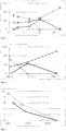
Fig. 3 zeigt eine graphische Darstellung der Abhängigkeit des Wertes der Wärmeleitfähigkeit (Abszisse in der Einheit mW/m*K) eines PU-Schaums gemessen bei 50 °C in Abhängigkeit von der Zusammensetzung des Zellgases (Ordinate in der Einheit Vol %). Die Quadrate repräsentieren Cyclopentan, die Kreise CO2, die Dreiecke HFO. -
Fig. 4 zeigt eine graphische Darstellung der durchschnittlichen Porengrösse(Abszisse in der Einheit µm) eines PU-Schaums in Abhängigkeit von der Zellgaszusammensetzung (Ordinate in der Einheit Vol%). Die Quadrate repräsentieren Cyclopentan, die Kreise CO2, die Dreiecke HFO. -
Fig. 5 zeigt eine graphische Darstellung der Viskosität (Abszisse in der Einheit mP*sec) eines Polyols mit verschiedenen Gehalten (Ordinate in der Einheit Gew %) von Cyclopentan bzw. HFO 1233zd. Die Quadrate repräsentieren Cyclopentan, die Dreiecke HFO. - In einem ersten Aspekt betrifft die Erfindung somit ein Rohrsystem enthaltend eine Wärmedämmung (auch vorisoliertes Rohrsystem oder thermisch gedämmtes Rohrsystem genannt), in welchem besagte Wärmedämmung einen Schaumstoff umfasst, dessen Zellgas Hydrofluorolefine (HFOs) enthält. Solche Rohrsysteme, jedoch ohne das genannte Zellgas, sind an sich bekannt und umfassen thermisch gedämmte Leitungsrohre, Muffen und Abdeckungsvorrichtungen zur Verbindung solcher Leitungsrohre.
- In einer ersten Ausgestaltung betrifft die Erfindung ein thermisch gedämmtes Leitungsrohr (1), umfassend mindestens ein Mediumrohr (4), mindestens eine um das Mediumrohr herum angeordnete Wärmedämmung (3) und mindestens einen um die Wärmedämmung herum angeordneten Aussenmantel (2), dadurch gekennzeichnet, dass besagter Aussenmantel (2) gegebenenfalls eine Barriere (9) aus Kunststoff umfasst, besagtes Mediumrohr (4) als ein flexibles Rohrstück ausgebildet ist und dass besagte Wärmedämmung (3) einen Schaumstoff umfasst, dessen Zellgas die nachstehend definierten Komponenten enthält.
- Dieser Aspekt der Erfindung soll nachstehend näher erläutert werden
Wärmedämmung (3): Die Wärmedämmung umschliesst das Mediumrohr teilweise oder vollständig, bevorzugt vollständig. Als Wärmedämmung sind insbesondere aufgeschäumte Kunststoffe ("Schaumstoffe") geeignet, die in Ihren Zellen ein Zellgas enthalten. Die Wärmedämmung kann entlang ihres Querschnitts homogen sein oder aus mehreren Lagen aufgebaut sein. Typischerweise ist die Wärmedämmung in Leitungsrohren homogen aufgebaut. - Zellgase: Als Zellgase werden die in der Wärmedämmung vorliegenden Gase bezeichnet. Diese sind eine Folge der Herstellung und setzen sich zusammen aus chemischen und physikalischen Treibmitteln, bzw. deren Reaktionsprodukten. Typischerweise werden solche Zellgase während des Schäumprozesses zugegeben, oder sie werden während des Schäumprozesses gebildet.
- Gemäss vorliegender Erfindung ist das Zellgas im Schaumstoff der Wärmedämmung dadurch gekennzeichnet, dass es Hydrofluorolefine (HFOs) enthält. Das Zellgas kann nur aus einem oder aus mehreren HFOs bestehen und ggf. zusätzlich weitere Komponenten enthalten. Erfindungsgemäß enthält das Zellgas 10-100 vol% HFOs, bevorzugt 20-100 vol% HFOs, mehr bevorzugt 30-100 vol% HFOs, besonders bevorzugt 40-100 vol% HFOs, ganz besonders bevorzugt 50-100 vol% HFOs. Entsprechend kann das Zellgas weitere Komponenten enthalten.
- In einer Ausgestaltung enthält das Zellgas 0-50 vol% (Cyclo)-Alkane, bevorzugt 0-45 vol% (Cyclo)-Alkane, mehr bevorzugt 0-40 vol% (Cyclo)-Alkane, besonders bevorzugt 0-35 vol% (Cyclo)-Alkane. Bevorzugt beträgt das Verhältnis HFOs zu (Cyclo)-Alkane mindestens 2.5:1, bevorzugt mindestens 3:1.
In einer weiteren Ausgestaltung enthält das Zellgas zusätzlich oder alternativ bis zu 50 vol% CO2, bevorzug 0-40 vol% CO2, besonders bevorzugt 0-30% CO2.
In einer weiteren Ausgestaltung enthält das Zellgas zusätzlich oder alternativ bis zu bis zu 5 vol% Stickstoff (N2) und/oder Sauerstoff (O2).
Diese weiteren Komponenten können dem Treibmittel zugesetzt werden, wie z.B. die genannten (Cyclo)-alkane; sie können während der Herstellung des Schaumstoffs entstehen, wie z.B. CO2; sie können während des Produktionsprozesses in den Schaumstoff gelangen, wie bspw. Luft, O2, N2. - Es hat sich überraschend gezeigt, dass bereits bei so geringen Anteilen wie bspw. 10 vol% HFO im Zellgas die Eigenschaften von Rohrsystemen, insbesondere von thermisch gedämmten Leitungsrohren, in einer Reihe von Merkmalen verbessern.
Namentlich wurde gefunden, dass die hier beschriebenen Leitungsrohre ein überraschend besseres Isolationsverhalten aufweisen. Ohne sich an eine Theorie gebunden zu fühlen wird davon ausgegangen, dass die verbesserten Isolationseigenschaften nicht nur durch Materialeigenschaften der HFOs (Wärmeleitfähigkeit) begründet sind, sondern auch durch ein verbessertes Aufschäumen, hervorgerufen durch die veränderte Viskosität. - Im Falle von PU-Schaumstoffen und PIR-Schaumstoffen führt die Zugabe von HFO zu einer der beiden Ausgangskomponenten (Isocyanat bzw Polyol) bzw. während der direkten Vermischung im Mischkopf zu einer markanten Viskositätserniedrigung. Ohne sich an eine Theorie gebunden zu fühlen wird davon ausgegangen, dass die verringerte Viskosität die Durchmischung der beiden Komponenten verbessert und dadurch die Ausbildung vergleichsweise kleinerer Zellen begünstigt.
- Um eine Viskositätsverringerung in ähnlicher Grössenordnung mit Cyclopentan als Treibmittel zu erreichen, könnte alternativ auch dessen Gehalt beispielsweise um das 1.86 fache gesteigert werden. Dies wäre der Faktor, um den sich die Molekulargewichte des HFO 1233zd (130.5 g/mol) und von Cyclopentan (70.2 g/mol) unterscheiden, dies hätte aber mehrere nachteilige Konsequenzen:
- a)Zum einen würde während des Schäumprozesses eine doppelte Menge des Treibgases expandieren, was zu unkontrollierbaren Veränderungen der Schaumstruktur führte. Existierende PU-Schäume und die Produktionsanlagen sind für die geringere Menge Cyclopentan optimiert und grosse mengenmässige Veränderungen hinsichtlich des expandierenden Treibmittels hätten umfangreiche Neuentwicklungen zur Folge.
- b) Cyclopentan wirkt als Weichmacher des PU-Schaums. Eine um das 1.86 fach erhöhte Menge führt zu dessen markanter Erweichung. Diese ist zum einen nicht gewünscht, weil der Schaum eine tragende Rolle spielt, d. h. für die mechanische Stabilität des gesamten Verbundes unabdingbar ist. Dies ist zum anderen nicht gewünscht, weil die zunehmende Weichheit des Schaums im Herstellungsprozess dazu führt, dass der gesamte Rohrverbund von der idealen runden Querschnittsgeometrie mehr und mehr abweicht. Somit wurde gefunden, dass der vollständige oder teilweise Ersatz von Cyclopentan durch HFOs die mechanischen Eigenschaften des Schaumstoffs verbessert. Üblicherweise wird dem Ausgangsmaterial Cyclopentan zugesetzt, um dessen Viskosität zu verringern; die Maximalmenge wird jedoch dadurch begrenzt, dass der erzeugte Schaumstoff ausreichende mechanische Festigkeit aufweisen muss. Durch den Ersatz von Cyclopentan durch HFOs können diese widerstrebenden Ziele erreicht werden. Der Einsatz einer vergleichbaren Menge HFO führt zu Ausgansmaterialien mit niedrigerer Viskosität bei gleichbleibender mechanischer Festigkeit des finalen Schaumstoffs. Somit kann bei gleichbleibender Produktqualität die Herstellbarkeit verbessert werden.
- Ferner wurde gefunden, dass die Zugabe des HFO zu einer der Ausgangskomponenten bzw. die direkte Zugabe zu den beiden Ausgangskomponenten im Mischkopf deren Brennbarkeit verringert. Dieser Effekt ist sehr von Vorteil, weil dadurch die sicherheitstechnischen Anforderungen an eine solche Produktionsanlage verringert sind und dadurch die Auslegung einer entsprechenden Produktionsanlage deutlich vereinfacht wird und somit Kosten eingespart werden können, welche andernfalls anfallen wenn mit brennbaren Treibmitteln gearbeitet wird.
- Zusammengefasst kann somit festgestellt werden, dass durch den teilweisen oder vollständigen Ersatz von Cyclopentan (Cp)durch HFOs die bekannten Probleme auf elegante Weise gelöst werden können. Einerseits kann mehr Treibmittel zugegeben werden, was zu einer gewünschten Viskositätsverringerung führt. Gleichzeitig bleibt aber die expandierende Wirkung im Wesentlichen unverändert und es benötigt keine grundlegenden Anpassungen an Rezeptur und Produktionsanlage. Schlussendlich wird durch den Ersatz des brennbaren Cyclopentan durch das unbrennbare HFO der Arbeitsschutz verbessert und die Investitionskosten für eine solche Produktionsanlage verringert.
- Es wurde ferner gefunden, dass hohe Gehalte an (Cyclo) Alkanen, insbesondere Cyclopentan, einen negativen Einfluss auf die Produktqualität haben. Erfahrungsgemäss führt ein zu hoher Gehalt an Cyclopentan im Polyol zu der Bildung von grossen Blasen im Schaum, die dadurch zustande kommen, dass das Treibmittel (insbes. Cyclopentan) durch die Temperatur des sich bildenden PU-Schaums aus dem Schaum ausgetrieben wird.
Bei einem kontinuierlich arbeitenden Produktionsprozess wird der Aussenmantel üblicherweise durch Extrusion aufgebracht und befindet sich zu diesem Zeitpunkt wegen der hohen Temperatur von typischerweise 80 - 250 °C in einem Zustand, in dem er leicht verformt werden kann. Die Blasen werden dann an der Aussenseite des isolierten Rohres sichtbar, weil das austretende Treibmittel den Aussenmantel aufbläht. Dies gilt gleichermassen für isolierte Rohre mit einem gewellten, einem glatten und einem korrugierten Aussenmantel. Das Austreten des Treibmittels wird gefördert durch die Temperatur des aufextrudierten Aussenmantels. Rohre mit solchen Defekten sind als Ausschuss zu betrachten und können nicht mehr der zweckmässigen Bestimmung zugeführt werden. - Die Bildung von Blasen wird verhindert, wenn der Gehalt des Cyclopentans an der Zellgaszusammensetzung des resultierenden isolierenden Schaums 0-50 Vol% beträgt, bevorzugt 0-45 Vol%, besonders bevorzugt 0-40 Vol%, meist bevorzugt 0-35 Vol%.
- Überraschenderweise wurde festgestellt, dass bei der Verwendung von HFO als Treibmittel die erwähnte Blasenbildung nicht eintritt. Dies gilt insbesondere wenn der Gehalt des HFO an der Zellgaszusammensetzung des resultierenden isolierenden Schaums in den vorstehend genannten Grenzen liegt. Das beschriebene Verhalten ist umso überraschender, da die Siedepunkte im Falle des HFO 1233zd 19 °C bzw. im Falle des HFO 1336mzz 33 °C betragen. Dies im Vergleich zu Cyclopentan, dessen Siedepunkt 49 °C beträgt. Aufgrund dieser Siedepunkte ist die Erwartung, dass die Bildung von Blasen bei der Verwendung des niedrig siedenden HFO als Treibmittel ausgeprägter wäre als bei der Verwendung höher siedender (Cyclo)-Alkane, z.B. Cp. Das Gegenteil wurde beobachtet.
- Hydrofluorolefine (HFOs) sind bekannt und kommerziell erhältlich bzw. nach bekannten Methoden herstellbar. Diese eignen sich als Treibgas, insbesondere wegen ihres geringen Treibhauspotentials (Global Warming Potential, GWP) und wegen ihrer Unschädlichkeit gegen die Ozonschicht der Atmosphäre (Ozone Depleting Potential, ODP). Der Begriff umfasst sowohl Verbindungen, die nur Kohlenstoff, Wasserstoff und Fluor umfassen, als auch solche Verbindungen, die zusätzlich Chlor enthalten (auch als HFCO bezeichnet) und jeweils mindestens eine ungesättigte Bindung im Molekül enthalten. HFOs können als Gemisch verschiedener Komponenten oder als reine Komponente vorliegen. HFOs können ferner als isomere Gemische, insbesondere E-/Z-Isomere, oder als isomerenreine Verbindungen vorliegen.
- Im Rahmen der vorliegenden Erfindung besonders geeignete HFOs sind ausgewählt aus der Gruppe umfassend Verbindungen der Formel (I)

- Besonders geeignete HFOs sind R1233zd (z.B. Solstice LBA, Fa. Honeywell) und R1336mzz (z.B. Formacel 1100, Fa. Du-Pont).
- Es hat sich überraschend gezeigt, dass die hier beschriebenen Leitungsrohre ein verbessertes Dämmverhalten aufweisen, wenn die Zellgase der Dämmung zumindest 10 vol%, bevorzugt zumindest 30 vol% besonders bevorzugt mindestens 50 vol% HFO enthalten. Es hat sich ferner gezeigt, dass die Zugabe von derartigen HFOs zu den Ausgangsmaterialien der Schaumstoffdämmung zu einer verbesserten Herstellbarkeit führt.
- (Cyclo)-Alkane sind als Zellgas der Dämmung in thermisch isolierten Rohren bekannt. Erfindungsgemäß ist das besagte Alkan bzw. Cycloalkan ausgewählt aus der Gruppe umfassend Propan, Butane, Pentane, Cyclopentan, Hexane, Cyclohexan. Durch die Kombination von (Cyclo)-Alkan mit HFO kann eine Feinjustierung der Produkteigenschaften erfolgen, und / oder die Herstellbarkeit verbessert werden und / oder eine Kostenreduktion mit vertretbaren Qualitätseinbussen erfolgen. Die genannten (Cyclo)-Alkane können als reine Verbindung oder als Gemische vorliegen; die aliphatischen Alkane können als isomerenreine Verbindungen oder als Isomerengemische vorliegen. Ein besonders geeignetes (Cyclo)-Alkan ist Cyclopentan.
- Kohlendioxid: Falls der Schaumstoff aus PU oder Polyisocyanurat (PIR) gebildet wird, entsteht typischerweise in gewisser Menge CO2, da das Ausgangsmaterial Polyol in technischer Qualität normalerweise eine kleine Menge Wasser enthält. Dieses reagiert dann mit dem Isocyanat zur Carbaminsäure, welche spontan CO2 abspaltet. Der CO2-Gehalt des Zellgases ist somit an die Reinheit der Ausgangsmaterialien geknüpft und liegt typischerweise unter 50 vol.%. Falls die Ausgangsmaterialien wasserfrei sind, bspw. wenn Polyolefine geschäumt werden, so ist der CO2-Gehalt des Zellgases bei 0 vol%. Der CO2-Gehalt des Zellgases kann somit über die Wahl der Ausgangsmaterialien (bzw. deren Reinheit) beeinflusst werden.
- Weitere Zellgase: Produktionsbedingt können aus der Atmosphäre / Umgebungsluft Komponenten in das Zellgas gelangen. Dies sind im Wesentlichen N2 und / oder O2, bspw. Luft. Der Gehalt an diesen Zellgasen liegt typischerweise unter 5 vol.%. Falls die Produktionsanlage speziell eingerichtet ist, so kann der Kontakt mit der Atmosphäre / Umgebungsluft vermieden werden und der Gehalt weiterer Zellgase ist bei 0 vol%.
- Schaumstoff: Die besagte Wärmedämmung (3) umfasst (d.h. enthält oder besteht aus) einen Schaumstoff. Solche Schaumstoffe sind an sich bekannt, besonders geeignet sind Schaumstoffe, welche die Normen DIN EN 253:2015-12 (insbesondere für KMR) und EN15632-1:2009/A1:2014, EN15632-2:2010/A1:2014 und EN15632-3:2010/A1:2014 (insbesondere für PMR) erfüllen. Der Begriff umfasst Hartschäume und Weichschäume. Schaumstoffe können geschlossenzellig oder offenzellig sein, bevorzugt geschlossenzellig, insebsondere wie in der Norm DIN EN 253:2015-12 dargelegt. Erfindungsgemäß werden solche Schaumstoffe ausgewählt aus der Gruppe der Polyurethane (PU), der Polyisocyanurate (PIR), der thermoplastischen Polyester (insbesondere PET), der thermoplastischen Polyolefine (insbesondere PE und PP).
- Es hat sich gezeigt, dass die folgenden Kombinationen aus Schaumstoff und Zellgas besonders vorteilhaft sind.:
- PU enthaltend 50-100 vol% R1233zd und 0-50 vol% Cp;
- PU enthaltend 50-100 vol% R1336mzz und 0-50 vol% Cp;
- PIR enthaltend 50-100 vol% R1233zd und 0-50 vol% Cp;
- PIR enthaltend 50-100 vol% R1336mzz und 0-50 vol% Cp;
- PET enthaltend 50-100 vol% R1233zd und 0-50 vol% Cp;
- PET enthaltend 50-100 vol% R1336mzz und 0-50 vol% Cp;
- PE enthaltend 50-100 vol% R1233zd und 0-50 vol% Cp;
- PE enthaltend 50-100 vol% R1336mzz und 0-50 vol% Cp.
- In einer Ausgestaltung ergänzen sich die genannten Zellgase zu 100 vol%. In einer weiteren Ausgestaltung ergänzen sich diese Zellglase zusammen mit CO2 und Luft zu 100%. In einer weiteren Ausgestaltung ist das Verhältnis von HFO : Cp mindestens 2.5:1.
- Es hat sich ferner gezeigt, dass die folgenden Kombinationen aus Schaumstoff und Zellgas besonders vorteilhaft sind:
- PU enthaltend 50-100 vol% R1233zd und 0-50vol% Cp und 0-50 vol% CO2;
- PU enthaltend 50-100vol% R1336mzz und 0-50 vol% Cp und 0-50 vol% CO2;
- PIR enthaltend 50-100vol% R1233zd und 0-50 vol% Cp und 0-50 vol% CO2;
- PIR enthaltend 50-100vol% R1336mzz und 0-50 vol% Cp und 0-50 vol% CO2
- PU enthaltend 50-100 vol% R1233zd und 0-45vol% Cp und 10-40 vol% CO2;
- PU enthaltend 50-100vol% R1336mzz und 0-45 vol% Cp und 10-40 vol% CO2;
- PIR enthaltend 50-100vol% R1233zd und 0-45 vol% Cp und 10-40 vol% CO2;
- PIR enthaltend 50-100vol% R1336mzz und 0-45 vol% Cp und 10-40 vol% CO2.
- In einer weiteren Ausgestaltung besteht die Wärmedämmung aus den genannten Schaumstoffen und den genannten Zellgasen.
- Barriere (9) : Diffusionsbarrieren sind im Bereich Leitungsrohre / Rohrsysteme an sich bekannt. Sofern eine Barriere vorliegt, ist diese Barriere als Schicht ausgebildet. Es ist bevorzugt, dass mindestens eine Barriere (9) wie nachstehend beschrieben vorliegt. Besonders bevorzugt ist, dass eine Barriere (9) wie nachstehend beschrieben vorliegt. Diese Schicht (9) ermöglicht, dass die Diffusion von Zellgasen aus der Wärmedämmung hinaus und von Gasen ausserhalb des Leitungsrohrs (insbesondere Luft) in die Wärmedämmung hinein reduziert wird. Diese Eigenschaft ist wichtig, um die Isolationsfähigkeit des Leitungsrohrs / Rohsystems über längere Zeit sicher zu stellen.
Diese Schicht ermöglicht in einer vorteilhaften Ausgestaltung ferner, dass die Diffusion von Wasser aus der Wärmedämmung heraus ermöglicht wird. Diese Eigenschaft ist insbesondere wichtig für Leitungsrohre / Rohrsysteme, deren Mediumrohr (4) aus Kunststoff besteht. Wird in derartigen Leitungsrohren / Rohrsystemen ein wässriges Medium transportiert, kann Wasser aus dem Medium durch das Leitungsrohr in die Dämmung gelangen und so die Isolationsfähigkeit vermindern und den Dämmstoff schädigen.
Diese Schicht ermöglicht in einer vorteilhaften Ausgestaltung ferner, eine gewisse Durchlässigkeit für CO2 gegeben ist. Ein besonders geeigneter Wert für die CO2 Durchlässigkeit liegt im Bereich von 0.5 - 100 cm3/m2*Tag*bar. Vorteilhaft ist daher eine Barriere mit selektiven Eigenschaften, insbesondere: (i) Permeabel für Wasser und Wasserdampf, (ii) impermeabel für die Zellgase, welche eine niedrige Wärmeleitfähigkeit aufweisen, (iii) permeabel für die Zellgase, die produktionsbedingt entstehen aber eine relativ hohe intrinsische Wärmeleitfähigkeit aufweisen (bspw. CO2), (iv) impermeabel für die Gase aus der Umgebung, insbesondere Stickstoff und Sauerstoff und Luft. - Es hat sich gezeigt, dass ein Leitungsrohr der eingangs genannten Art, bei dem die Barriere eines oder mehrere der nachstehend genannten Polymere umfasst, die Anforderungen sehr gut erfüllt. Erfindungsgemäss kann die Barriere in einer einzigen Schicht vorliegen oder in mehreren, voneinander getrennten Schichten. Ferner kann die Barriere mittels einer zusätzlichen Schicht an die Dämmung oder den Aussenmantel oder im Aussenmantel angebracht sein ("Haftvermittlerschicht" (8), (10)).
Die Barriere (9) kann als Schicht im Aussenmantel (2) angeordnet sein; dies ist bevorzugt, insbesondere ist diese Ausgestaltung bevorzugt mit zwei an die Barriere (9) angrenzenden Haftvermittlerschichten (8, 10) wie inFig. 2 dargelegt.
Ferner kann die Barriere als Schicht auf der Aussenseite und / oder der Innenseite des Aussenmantels angeordnet sein. Ferner kann die Barriere vom Aussenmantel gebildet werden. Ferner kann die Barriere (9) als Schicht zwischen der Wärmedämmung (3) und dem Aussenmantel (2) angeordnet sein. In dieser Ausgestaltung entfällt typischerweise die Haftvermittlerschicht.
Vorteilhaft weist die Barriereschicht (9) eine Schichtdicke von 0.05 - 0.5 mm, bevorzugt 0.1 - 0.3 mm auf. Falls die Barriere den Aussenmantel bildet, weist die Barriere vorteilhaft eine Schichtdicke von 0.5 - 5 mm auf. Sofern vorhanden, weisen die Haftvermittlerschichten (8, 10) unabhängig voneinander vorteilhaft eine Schichtdicke von 0.02 - 0.2 mm auf. - Bevorzugt umfasst die Barriere ein Co-Polymer des Ethylens mit Kohlenmonoxid oder mit Vinylalkohol.
- In einer vorteilhaften Ausgestaltung umfasst die Barriere ein Polymer, welches Polyketone enthält oder aus Polyketonen besteht. Entsprechend umfasst die Polymerschicht Polyketone und Blends von Polyketonen sowie Laminate enthaltend Polyketone. Polyketone sind an sich bekannte Materialien und charakterisiert durch die Keto-Gruppe (C=O) in der Polymerkette. In dieser Ausgestaltung weist dass das Polymer vorteilhaft zu 50 - 100 Gew.%, bevorzugt zu 80-100 Gew.%, Struktureinheiten Formeln (II) oder der Formel (III) auf.

- o
- für 1 oder 2, bevorzugt 1, steht,
- p
- für 1 oder 2, bevorzugt 1, steht,
- q
- für 1-20 steht und
- r
- für 1-20 steht.
- In einer vorteilhaften Ausgestaltung umfasst die Barriere ein Polymer, welches Ethyl-vinylalkohol enthält oder aus Ethyl-vinylalkohol besteht.
In dieser Ausgestaltung weist dass das Polymer zu 50 - 100 Gew.%, bevorzugt zu 80-100 Gew.%, Struktureinheiten der Formel (IV) auf.
- m für 1-10 steht,
- n für 2-20 steht.
- Die Kombination von Zellgasen aus der Gruppe der Hydroolefine und Barriereschichten gemäss den hier beschriebenen Formeln (II), (III), (IV) führt zu besonders guten, überadditiven Isolationseigenschaften der thermisch isolierten Leitungsrohre. Ein derartiges positives Zusammenwirken dieser Komponenten ist überraschend. Ohne sich an eine Theorie gebunden zu fühlen kann dieser überadditive Effekt auf die Barriereeigenschaften der Materialien gemäss Formeln (II), (III), (IV) zurück geführt werden.
- Mediumrohr (4): Grundsätzlich können alle für thermisch gedämmte Rohre geeignete Mediumrohre verwendet werden. Entsprechend kann das Mediumrohr als Wellrohr, als glattes Rohr oder als Rohr mit einem korrugierten Mantel ausgebildet sein; es ist als ein flexibles Rohrstück ausgebildet.
- Das Mediumrohr kann aus polymerem Werkstoffen oder metallischen Werkstoffen, bevorzugt aus polymeren Werkstoffen bestehen. Solche Materialien sind an sich bekannt und sind kommerziell erhältlich oder nach bekannten Verfahren hergestellt. Die Materialien werden vom Fachmann nach Einsatzzweck, ggf. nach Routineversuchen, ausgewählt.
- In einer Ausgestaltung ist besagtes Mediumrohr (4) ein flexibles Kunststoffrohr, der Kunststoff ausgewählt aus der Gruppe Acrylnitril-Butadien-Styrol (ABS), vernetztes Polyethylen (PEXa, PEXb, PEXc), PE, Polybuten (PB), Polyethylen Raised Temperature (PE-RT), und Polyketon (PK).
- In einer weiteren Ausgestaltung ist besagtes Mediumrohr (4) ein flexibles Kunststoffrohr mit einer äusseren Metallschicht, der Kunststoff ausgewählt aus der Grupp ABS, PEXa, PEXb, PEXc, PE, PB, PE-RT und PK, das Metall ausgewählt aus der Gruppe Aluminium einschliesslich dessen Legierungen. Solche Innenrohre sind auch als Verbundrohre bekannt.
- In einer weiteren Ausgestaltung ist besagtes Mediumrohr (4) ein flexibles Metallrohr, das Metall ausgewählt aus der Gruppe Kupfer einschliesslich dessen Legierungen, Eisen einschliesslich dessen Legierungen (wie z.B nichtrostende Stähle), Aluminium einschliesslich dessen Legierungen.
- In einer weiteren Ausgestaltung des Mediumrohrs (4) kann die bereits erwähnte Barriere aus Kunststoff auf der Aussenseite des Innenrohrs angeordnet sein oder sie kann vom Mediumrohr selber gebildet werden. Eine Barriere auf dem Mediumrohr, oder vom Mediumrohr selber gebildet, verringert die Diffusion von Dampf aus dem Mediumrohr in die Wärmedämmung. Erfindungsgemäss wird eine solche ("zweite") Barriere mit einer weiteren ("ersten") Barriere oberhalb der Wärmedämmung kombiniert.
- Aussenmantel (2): Grundsätzlich können alle für thermisch gedämmte Rohre geeigneten Aussenmäntel verwendet werden. Entsprechend kann der Aussenmantel als Wellrohr oder als solches mit einem korrugierten Mantel ausgebildet sein. Es kann ein starres und gerades Rohrstück, ein starres gebogenes Rohrstück oder ein flexibles Rohrstück sein.
- Der Aussenmantel kann aus polymerem Werkstoffen oder metallischem Werkstoffen, bevorzugt aus polymeren Werkstoffen bestehen. Solche Materialien sind an sich bekannt und sind kommerziell erhältlich oder nach bekannten Verfahren hergestellt. Die Materialien werden vom Fachmann nach Einsatzzweck, ggf. nach Routineversuchen, ausgewählt. Vorteilhaft kommen thermoplastische Polymere, wie kommerzielle PE Typen, zum Einsatz. Geeignet sind PE hoher Dichte (HDPE), PE niedriger Dichte (LDPE), lineares PE niedriger Dichte (LLDPE). Die Schichtdicke des Aussenmantels (2) kann in weiten Bereichen variieren, liegt aber typischerweise bei 0.5 - 20 mm, inkl. der möglicherweise vorliegenden Barriere und Sperrschichten.
- In einer Ausgestaltung der Erfindung enthält der Aussenmantel die hier beschriebene Barriere, wie vorstehend beschrieben. Diese Ausgestaltung ist vorteilhaft, da mittels Coextrusion Mantel und Barriere gleichzeitig und somit kostengünstig erzeugt werden können.
- In einer alternativen Ausgestaltung der Erfindung enthält der Aussenmantel die hier beschriebene Barriere, wie vorstehend beschrieben, nicht. In dieser Ausgestaltung liegt die Barriere als separate Schicht vor. Diese Ausgestaltung ist vorteilhaft, da Mantel und Barriere separat und somit flexibel erstellt werden können.
- In einer vorteilhaften Ausführungsform betrifft die Erfindung ein Leitungsrohr wie hier beschrieben, in welchem besagter Aussenmantel (2) als Wellrohr ausgebildet ist; und besagtes Mediumrohr als ein flexibles Rohrstück ausgebildet ist und insbesondere mindestens ein Mediumrohr auf der Basis von Polyethylen aufweist und eine Wärmedämmung auf der Basis von PU und einen Aussenmnatel auf der Basis von Poylethylen.
- In einer weiteren vorteilhaften Ausführungsform betrifft die Erfindung ein Leitungsrohr wie hier beschrieben, in welchem besagter Aussenmantel (2) als korrugiertes Rohr ausgebildet ist. Vorteilhafterweise werden solche Leitungsrohre mit einem Mediumrohr kombiniert, welches als flexibles Rohrstück ausgebildet ist und insbesondere mindestens ein Mediumrohr auf der Basis von Polyethylen oder vernetztem Polyethylen umfasst. Vorteilhafterweise werden solche Leitungsrohre ferner mit einer Wärmedämmung (3) versehen, die einen Schaumstoff umfasst, dessen Zellgas die vorstehend genannten Zusammensetzung aufweist (wobei das Zellgas besonders bevorzug zu höchstens 35% (Cyclo)Alkane enthält).
- In einem zweiten Aspekt betrifft die Erfindung Verfahren zur Herstellung von thermisch gedämmten Leitungsrohren, wie hier beschrieben. Der Erfindung liegt entsprechend die Aufgabe zu Grunde, verbesserte Verfahren zur Herstellung eines Leitungsrohrs zu schaffen, welches sowohl kontinuierlich als auch diskontinuierlich geführt werden kann.
- Dieser Aspekt der Erfindung soll nachstehend näher erläutert werden.
- Grundsätzlich können die hier beschriebenen thermisch isolierten Vorrichtungen (vgl. erster Aspekt der Erfindung) in Analogie zu den bekannten Verfahren hergestellt werden. Dabei werden die bekannten Treibmittel (blowing agents, bspw. Cyclopentan, CO2) durch die hier beschriebenen HFOs teilweise oder vollständig ersetzt. Entsprechend können an sich bekannte Anlagen für die Herstellung verwendet werden, ggf. nach Anpassung an neue Parameter, wie sie der Fachmann in seiner Routinetätigkeit durchführen kann. Die in den eingangs genannten Dokumenten
EP0897788 undEP2213440 undEP2248648 undWO2008/019791 undEP1355103 undEP2340929 beschriebenen Verfahren werden hiermit durch Referenz aufgenommen. - In einer vorteilhaften Ausführungsform des Verfahrens wird die Wärmedämmung (3) durch Aufschäumen einer Kunststoffzusammensetzung gebildet, welche Polymerkomponenten zur Schaumstoffbildung und HFO als Treibmittel enthält. Erfindungsgemäss kann das HFO entweder einer der Komponenten zudosiert werden und dann verarbeitet werden oder die Ausganskomponenten und das HFO werden gleichzeitig in einer Dosiervorrichtung (bspw. der Mischkopf) kombiniert.
- In einer weiteren vorteilhaften Ausführungsform des Verfahrens umfasst die Kunststoffzusammensetzung zwei flüssige Komponenten, wobei die erste Komponente ein Polyol und HFO enthält und die zweite Komponente Isocyanat enthält. Bei der Isocyanat Komponente handelt es sich bevorzugt um solche auf der Basis von Methylendiisocyanat. Aber auch andere Isocyanate wie beispielsweise solche auf der Basis von Toluol-2,4-diisocyanat oder aliphatischen Isocyanaten können verwendet werden.
- In einer weiteren vorteilhaften Ausführungsform des Verfahrens umfasst die Kunststoffzusammensetzung zwei flüssige Komponenten, wobei die erste Komponente ein Polyol enthält und die zweite Komponente Isocyanat und HFO enthält. Insbesondere solche HFO Komponenten sind bevorzugt, welche eine gute Mischbarkeit mit den beiden flüssigen Komponenten aufweisen und deren Siedepunkt nicht zu niedrig liegt (insbesondere nicht unter 10 °C). Dadurch wird der apparative Aufwand in der Produktion gering; Kühlanlagen müssen nur in geringem Umfang bereitgestellt werden.
- In einer weiteren vorteilhaften Ausführungsform des Verfahrens besteht die Kunststoffzusammensetzung aus einer geschmolzenen Komponente und diese Schmelze wird mit HFO unter Druck kombiniert.
- Variante 1: Sofern das thermisch gedämmte Rohr dieser Erfindung ein oder mehrere flexible(s) Mediumrohr(e) umfasst und der Aussenmantel (13) eine Barriere aus Kunststoff, ist eine Verfahrensvariante vorteilhaft, in welcher
- (a) das mindestens eine Mediumrohr kontinuierlich zugeführt wird und mit einer zu einem Schlauch geformten Kunststofffolie umhüllt wird,
- (b) in den Raum zwischen Mediumrohr und Schlauch eine aufschäumbarer Kunststoffzusammensetzung als Wärmedämmschicht eingebracht wird,
- (c) das Mediumrohr und der Schlauch in ein aus mitlaufenden Formteilen gebildetes Werkzeug eingebracht werden und dieses Werkzeug an dessen Ende verlassen, und danach
- (d) auf die Oberfläche des Schlauches der Aussenmantel extrudiert wird,
- die Barriere zwischen der aufgeschäumten Wärmedämmschicht und der Innenseite des Aussenmantels eingebracht werden, indem der Schlauch aus dem Polymer gebildet wird; oder
- die Barriere durch Coextrusion zusammen mit dem Aussenmantel aufgebracht werden; oder
- die Barriere direkt auf den Schlauch aufgebracht werden; oder
- zunächst eine Schicht des Aussenmantels, gefolgt durch die Barriere und gefolgt durch mindestens eine zweite Schicht des Aussenmantels aufgebracht werden.
- kontinuierlich von einem Vorrat abgezogen werden; oder
- kontinuierlich durch Extrusion hergestellt werden.
- Variante 3: Sofern das thermisch gedämmte Rohr dieser Erfindung eine Wärmedämmung aus einem thermoplastischen Schaum, also bspw. aus PET, PE oder PP enthält, ist eine Verfahrensvariante vorteilhaft, in welcher das HFO direkt in die geschmolzene Polymermatrix eingepresst wird und nachfolgend durch Expansion zum Aufschäumen des verwendeten Thermoplasts führt. Dies kann bspw. dadurch geschehen, dass eine Polymermischung im Extruder aufgeschmolzen wird und in diese Schmelze HFO unter Druck zugeführt wird. Beim Verlassen des Werkzeugs führt das vorhandene Treibmittel zum Aufschäumen.
- In einem dritten Aspekt betrifft die Erfindung neue Verwendungen von HFOs.
- Dieser Aspekt der Erfindung soll nachstehend näher erläutert werden.
- In einer ersten Ausgestaltung betrifft die Erfindung Verwendung von Hydrofluorolefinen als Zellgas der Schaumstoffdämmung in Kunststoffmediumrohrsystemen (PMR).
- Vorteilhaft können HFOs als Zellgas in Schaumstoffdämmungen von Leitungsrohren wie hier (erster Aspekt) beschrieben verwendet werden.
- Die Erfindung wird anhand der nachfolgenden Beispiele näher erläutert; diese sollen die Erfindung in keiner Weise limitieren.
- Von einer Vorratstrommel wurden Mediumrohre mit einem Aussendurchmesser von 63 mm und einer Wanddicke von 5.8 mm bestehend aus PExa kontinuierlich abgewickelt. Kurz vor der Schäumstation wurde dieses Mediumrohr von einer PE-Folie umschlossen, welche ihrerseits von einem Vorrat abgewickelt und über eine Formschulter zugeführt wurde. In die an der oberen Seite noch geöffneten Schlauchfolie wurde die entsprechende Menge eines Gemischs aus einem polymeren Isocyanat auf der Basis von Diphenylmethylendiisocyanat (MDI) mit einem NCO-Gehalt von 31 % und einem Polyol mit einer OH-Zahl von 410 mg KOH/g (bestimmt nach ASTMD4274D) und mit einem Wassergehalt von 0.8%) zugegeben. Die Isocyanat Komponente wurde dabei leicht überstöchiometrisch relativ zu den reaktiven OH-Gruppen eingesetzt. Die beiden Komponenten wurden vor der Zudosierung in einem Hochdruckmischkopf mit einem Druck von 150 bar intensiv durchmischt. In die Polyol Komponente ihrerseits wurde vorgängig die entsprechende Menge HFO / Cyclopentan eingerührt. Unmittelbar nach der Zugabe des Zweikomponenten Gemischs wurde die Schlauchfolie am oberen Ende verschweisst. Der unmittelbar danach entstehende PU-Schaum wurde durch Formbacken in eine zylindrische Geometrie gezwungen und nach dem Aushärten wurde kontinuierlich ein Mantel aus PE aufextrudiert.
- Die erhaltenen Rohre wurden bezüglich der im Schaum enthaltenen Zellgase analysiert. Zu diesem Zweck wurden kleine Proben von etwa 3 cm3 Grösse aus dem Schaum gestanzt und diese in einem geschlossenen System mechanisch zerstört, so dass die Zellgase in die Messappartur gelangen konnten. Die vorhandenen Gase wurden qualitativ und quantitativ in einem Gaschromatographen bestimmt.
- Ausserdem wurde an 3 m langen Rohrstücken der Wert der Wärmeleitfähigkeit bei 50 °C gemäss den Normen DIN EN 253:2015-12 und EN ISO 8497:1996 (λ50-Wert) gemessen. Ferner wurde die Zusammensetzung des Zellgases (gemäss dem Chalmers-Verfahren; beschrieben in Rämnas et al, J. Cellular Plastics, 31, 375-388, 1995) bestimmt; diese Methode wurde auch in den Nachfolgenden Beispielen verwendet. Die Zusammenfassung der Ergebnisse findet sich in der folgenden Tabelle, eine graphische Darstellung ist in
Figur 3 ersichtlich:Zellgas Einheit No1.1 No1.2 No1.3 No1.4 No1.5 CO2* [Vol %] 100 51 34 31 32 Cp [Vol %] 0 46 14 9 0 HFO 1233zd [Vol %] 0 0 49 59 65 O2 + N2 [Vol %] 0 3 3 1 3 λ50-Wert [mW/m*K] 25.8 23.1 21.7 20.2 19.6 * CO2 bildet sich zwangsweise als Nebenprodukt aus den Ausgangskomponenten und wird nicht zudosiert (Chem. Treibmittel). - Die Daten belegen klar den positiven Einfluss von HFO auf die Wärmeleitfähigkeit.
- In einem Becherglas wurde jeweils eine Menge von 380 - 420 g Polyol vorgelegt und die in der Tabelle angegebene Menge Treibmittel eingerührt. Die Viskosität der Lösung wurde bestimmt in einem Rotationsviskosimeter des Typs Viscometer DV I-Prime der Fa Brookfield. Es wurde der Durchschnittswert aus drei Messungen aufgenommen.
- Die Ergebnisse sind in der Tabelle zusammengefasst und in
Fig. 5 graphisch dargestellt.Treibmittel Gehalt an zugegebenem Treibmittel Temperatur Viskosität [mol/100 g Polyol] [K] [mPa*s] Polyol Reines Polyol, ohne Treibmittel 292.8 2005 Cp 0.043 293.2 1245 0.071 293.1 946 HFO 1233zd 0.041 293.0 1151 0.071 293.1 815 - Die Daten belegen klar den positiven Einfluss von HFO auf die Viskosität.
- Gemäss DIN EN 253:2015-12 wurde die durchschnittliche Porengrösse von PU-Schäumen, welche unterschiedliche Zellgase beinhalteten, bestimmt. Es wurde jeweils ein Durchschnitt aus drei Messungen gebildet.
- Die Ergebnisse sind in der Tabelle zusammengefasst und in
Figur 4 graphisch dargestellt:Zellgas Einheit No3.1 No3.2 No3.3 CO2 [Vol %] 100 51 32 Cp [Vol %] 0 46 0 HFO 1233zd [Vol %] 0 0 65 O2 + N2 [Vol %] 0 3 3 Porengrösse [µm] 151.0 138.1 130.6 - Die Daten belegen klar den positiven Einfluss von HFO auf die Zellgrösse.
- Gemäss der Methode nach Pensky-Martens (DIN EN ISO 2719:2003-9) wurden die Flammpunkte der Muster No 1 und No 3 bestimmt. Das Muster No 2 wurde gemäss der Methode nach Abel-Pensky (DIN 51755) vermessen. Es wurde jeweils das gleiche Polyol verwendet wie im Beispiel 1. Die Ergebnisse sind in der Tabelle zusammengefasst.
Komponente Einheit No4.1 No4.2 No4.3 Polyol [g/100 g Polyol] 100 100 100 Cp [g/100 g Polyol] 0 4.8 0 HFO 1233zd [g/100 g Polyol] 0 0 8.9 Flammpunkt normiert auf 1013 mbar [°C] 102.8 < - 21 > 56 - Die Probe No 3 hat einen Flammpunkt, der deutlich höher liegt als die Vergleichsprobe No 2, welche einen äquivamolaren Gehalt an Cyclopentan enthält. Insbesondere ist die Probe No 3 nicht als entzündlich einzustufen gemäss der Verordnung EG 440/2008.
- Allgemein: Entsprechend Beispiel 1 wurden thermisch gedämmte Leitungsrohre mit verschiedenen Zellgaszusammensetzungen hergestellt.
- Beispiel 5.1 (Vergleichsversuch): In die Polyol Komponente wurde mit Hilfe eines Statikmischers eine Menge Cyclopentan (Cp) zudosiert, so dass sich bezogen auf die Polyolmenge ein Gehalt von 7 Gew % ergab. An der Oberfläche des so produzierten Rohres wurden auf einer Länge von 30 cm zwölf Blasen gezählt, welche einen Durchmesser grösser 10 mm aufwiesen und auch ohne weitere Hilfsmittel einfach zu erkennen waren.
- Beispiel 5.2 In das Polyol eine Menge von 2 Gew % Cyclopentan und 11 Gew % HFO 1233zd zudosiert. An der Oberfläche des so produzierten Rohres wurden auf einer produzierten Länge von 400 m keine Blasen festgestellt.
- Beispiel 5.3: In das Polyol eine Menge von 15 Gew % HFO 1233zd zudosiert. An der Oberfläche des so produzierten Rohres wurden auf einer produzierten Länge von 350 m keine Blasen festgestellt.
- Ergebnisse der Beispiele 5.1-5.3: Die so erhaltene Zusammensetzung der Zellgase wurde wie in Beispiel 1 mittels GC bestimmt, das erhaltene Rohr wurde visuell kontrolliert.
Bsp. Zusammensetzung Zellgas Kontrolle 5.1 (Vergleich) 69% Cp 12 Blasen auf 0.3m Länge unbrauchbar 29% CO2 0% HFO 2% H2+ N2 5.2 17% Cp 0 Blasen auf 400m Länge fehlerfrei 27% CO2 55% HFO 1% H2+ N2 5.3 0% Cp 0 Blasen auf 350m Länge fehlerfrei 27% CO2 71% HFO 2% H2+ N2 - Die Daten belegen, dass hohe Mengen Cp zu unbrauchbaren gedämmten Leitungsrohren führen, wohingegen deren teilweiser oder vollständiger Ersatz durch HFO zu fehlerfeien gedämmten Rohren führt.
- Während in der vorliegenden Beschreibung bevorzugte Ausführungen der Erfindung beschrieben sind, ist darauf hinzuweisen, dass die Erfindung nicht auf diese beschränkt ist und in auch anderer Weise innerhalb des Umfangs der folgenden Ansprüche ausgeführt werden kann.
- Abel-Pensky (DIN 51755) vermessen. Es wurde jeweils das gleiche Polyol verwendet wie im Beispiel 1. Die Ergebnisse sind in der Tabelle zusammengefasst.
Komponente Einheit No4.1 No4.2 No4.3 Polyol [g/100 g Polyol] 100 100 100 Cp [g/100 g Polyol] 0 4.8 0 HFO 1233zd [g/100 g Polyol] 0 0 8.9 Flammpunkt normiert auf 1013 mbar [°C] 102.8 < - 21 > 56 - Die Probe No 3 hat einen Flammpunkt, der deutlich höher liegt als die Vergleichsprobe No 2, welche einen äquivamolaren Gehalt an Cyclopentan enthält. Insbesondere ist die Probe No 3 nicht als entzündlich einzustufen gemäss der Verordnung EG 440/2008.
- Allgemein: Entsprechend Beispiel 1 wurden thermisch gedämmte Leitungsrohre mit verschiedenen Zellgaszusammensetzungen hergestellt.
- Beispiel 5.1 (Vergleichsversuch): In die Polyol Komponente wurde mit Hilfe eines Statikmischers eine Menge Cyclopentan (Cp) zudosiert, so dass sich bezogen auf die Polyolmenge ein Gehalt von 7 Gew % ergab. An der Oberfläche des so produzierten Rohres wurden auf einer Länge von 30 cm zwölf Blasen gezählt, welche einen Durchmesser grösser 10 mm aufwiesen und auch ohne weitere Hilfsmittel einfach zu erkennen waren.
- Beispiel 5.2 In das Polyol eine Menge von 2 Gew % Cyclopentan und 11 Gew % HFO 1233zd zudosiert. An der Oberfläche des so produzierten Rohres wurden auf einer produzierten Länge von 400 m keine Blasen festgestellt.
- Beispiel 5.3: In das Polyol eine Menge von 15 Gew % HFO 1233zd zudosiert. An der Oberfläche des so produzierten Rohres wurden auf einer produzierten Länge von 350 m keine Blasen festgestellt.
- Ergebnisse der Beispiele 5.1-5.3: Die so erhaltene Zusammensetzung der Zellgase wurde wie in Beispiel 1 mittels GC bestimmt, das erhaltene Rohr wurde visuell kontrolliert.
Bsp. Zusammensetzung Zellgas Kontrolle 5.1 (Vergleich) 69% Cp 12 Blasen auf 0.3m Länge unbrauchbar 29% CO2 0% HFO 2% H2+ N2 5.2 17% Cp 0 Blasen auf 400m Länge fehlerfrei 27% CO2 55% HFO 1% H2+ N2 5.3 0% Cp 0 Blasen auf 350m Länge fehlerfrei 27% CO2 71% HFO 2% H2+ N2 - Die Daten belegen, dass hohe Mengen Cp zu unbrauchbaren gedämmten Leitungsrohren führen, wohingegen deren teilweiser oder vollständiger Ersatz durch HFO zu fehlerfeien gedämmten Rohren führt.
- Während in der vorliegenden Beschreibung bevorzugte Ausführungen der Erfindung beschrieben sind, ist darauf hinzuweisen, dass die Erfindung nicht auf diese beschränkt ist und in auch anderer Weise innerhalb des Umfangs der folgenden Ansprüche ausgeführt werden kann.
Claims (18)
- Thermisch gedämmtes Leitungsrohr (1), umfassend mindestens ein Mediumrohr (4), mindestens eine um das Mediumrohr herum angeordnete Wärmedämmung (3) und mindestens einen um die Wärmedämmung herum angeordneten Aussenmantel (2), dadurch gekennzeichnet, dass
besagtes Mediumrohr (4) als ein flexibles Rohrstück ausgebildet ist, und
besagter Aussenmantel (2) gegebenenfalls eine Barriere (9) aus Kunststoff umfasst, und
besagte Wärmedämmung (3) einen Schaumstoff umfasst, dessen Zellgas 10-100 vol% Hydrofluorolefine (HFOs) und 0-50 vol% (Cyclo)-Alkane und 0-50 vol% CO2 enthält, und wobei
besagtes HFO ausgewählt ist aus der Gruppe umfassend Verbindungen der Formel (I)
besagtes Alkan ausgewählt ist aus der Gruppe umfassend Propan, Butane, (Cyclo)-Pentane, (Cyclo)-Hexane und wobei
besagte Wärmedämmung (3) einen Schaumstoff, ausgewählt aus der Gruppe der Polyurethane (PU), der Polyisocyanurate (PIR), der thermoplastischen Polyester (PET) und der thermoplastischen Polyolefine, enthält. - Leitungsrohr nach Anspruch 1, dadurch gekennzeichnet, dass besagter Aussenmantel (2) als Wellrohr oder als korrugiertes Rohr ausgebildet ist und besagtes Mediumrohr (4) als ein flexibles Rohrstück ausgebildet ist.
- Leitungsrohr nach einem der Ansprüche 1 oder 2 dadurch gekennzeichnet, dass besagtes Zellgas 10-100 vol% HFOs und 0-50 vol% (Cyclo)-Alkane und 0-50 vol% CO2 enthält und mit der Massgabe, dass das Verhältnis HFOs zu (Cyclo)-alkane mindestens 2.5:1 beträgt.
- Leitungsrohr nach einem der Ansprüche 1, 2 oder 3, dadurch gekennzeichnet, dass besagtes HFO ausgewählt ist aus der Gruppe umfassend Verbindungen der Formel (I) welche für R1233zd, und / oder R1336mzz stehen.
- Leitungsrohr nach Anspruch 1, dadurch gekennzeichnet, dass besagte Wärmedämmung (3) einen Schaumstoff, ausgewählt aus der Gruppe der Polyurethane (PU) enthält.
- Leitungsrohr nach einem der Ansprüche 1 bis 5, dadurch gekennzeichnet, dass besagter Schaumstoff ausgewählt ist aus- PU enthaltend 50-100vol% R1233zd und 0-50vol% Cyclopentan als Zellgas;- PU enthaltend 50-100vol% R1336mzz und 0-50vol% Cyclopentan als Zellgas;- PIR enthaltend 50-100vol% R1233zd und 0-50vol% Cyclopentan als Zellgas;- PIR enthaltend 50-100vol% R1336mzz und 0-50vol% Cyclopentan als Zellgas;- PET enthaltend 50-100vol% R1233zd und 0-50vol% Cyclopentan als Zellgas;- PET enthaltend 50-100vol% R1336mzz und 0-50vol% Cyclopentan als Zellgas;- PE enthaltend 50-100vol% R1233zd und 0-50vol% Cyclopentan als Zellgas; und / oder- PE enthaltend 50-100vol% R1336mzz und 0-50vol% Cyclopentan als Zellgas.
- Leitungsrohr nach einem der Ansprüche 1 bis 6, dadurch gekennzeichnet, dass eine Barriere (9) vorliegt, die als Schicht ausgebildet ist,- welche die Diffusion von Gasen aus der Wärmedämmung hinaus und in die Wärmedämmung hinein reduziert, und- welche die Diffusion von Wasser aus der der Wärmedämmung heraus ermöglicht.
- Leitungsrohr nach einem der Ansprüche 1 bis 7, dadurch gekennzeichnet, dass die Barriere (9)- als Schicht auf der Wärmedämmung; und/oder- als Schicht auf der Innenseite des Aussenmantels; und / oder- als Schicht im Aussenmantel angeordnet ist.
- Leitungsrohr nach einem der Ansprüche 1 bis 8, dadurch gekennzeichnet, dass die Barriere (9)- ein Co-Polymer aus Ethylen und Vinylalkohol oder ein Co-Polymer aus Ethylen und Kohlenmonoxid oder ein Co-Polymer aus Ethylen und Kohlenmonoxid und Propylen umfasst, und- eine Schichtdicke von 0.05-0.5 mm aufweist.
- Leitungsrohr nach Anspruch 9, dadurch gekennzeichnet, dass das Polymer zu 50 - 100 Gew.%, Struktureinheiten der Formel (II) oder (III) oder (IV) enthält,
 m für 1-10 steht,n für 2-20 steht, [mit m/n 30/100 bis 50/100]o für 1 oder 2, bevorzugt 1, steht,p für 1 oder 2, bevorzugt 1, steht,q für 1-20 steht undr für 1-20 steht.
 - Leitungsrohr nach einem der Ansprüche 1 bis 10, dadurch gekennzeichnet, dass besagtes Mediumrohr (4)- ein flexibles Kunststoffrohr ist, der Kunststoff ausgewählt aus der Gruppe ABS, PEXa, PEXb, PEXc, PE, Polybuten (PB), Polyethylen Raised Temperature (PE-RT), und Polyketon (PK); oder- ein flexibles Kunststoffrohr mit einer äusseren Metallschicht ist, der Kunststoff ausgewählt aus der Gruppe ABS, PEXa, PEXb, PEXc, PE, Polybuten (PB), Polyethylen Raised Temperature (PE-RT), und Polyketon (PK), das Metall ausgewählt aus der Gruppe Aluminium; oder- ein flexibles Metallrohr ist, das Metall ausgewählt aus der Gruppe Kupfer einschliesslich dessen Legierungen, Eisen einschliesslich dessen Legierungen, Aluminium einschliesslich dessen Legierungen.
- Leitungsrohr nach einem der Ansprüche 1 bis 11, dadurch gekennzeichnet, dass besagte Wärmedämmung (3) einen geschlossenzelligen Schaumstoff umfasst, dessen Zellgas• zu 10-100 vol% aus Hydrofluorolefinen (HFOs),• zu 0-50 vol% aus (Cyclo)-Alkanen,• zu 0-50 vol% aus CO2, und• zu 0-5 vol% aus Stickstoff und/oder Sauerstoff besteht.
- Verfahren zur Herstellung eines thermisch gedämmten Leitungsrohrs, nach einem der Ansprüche 1 bis 12, dadurch gekennzeichnet, dass
die Wärmedämmung (3) durch Aufschäumen einer Kunststoffzusammensetzung gebildet wird, welche Polymerkomponenten zur Schaumstoffbildung und HFO als Treibmittel enthält. - Verfahren nach Anspruch 13, dadurch gekennzeichnet,- dass die Kunststoffzusammensetzung zwei flüssige Komponenten umfasst, wobei die erste Komponente ein Polyol und HFO enthält und die zweite Komponente Isocyanat enthält; oder- dass die Kunststoffzusammensetzung zwei flüssige Komponenten umfasst, wobei die erste Komponente ein Polyol enthält und die zweite Komponente Isocyanat und HFO enthält; oder- dass die Kunststoffzusammensetzung aus einer geschmolzenen Komponente besteht und diese Schmelze mit HFO unter Druck kombiniert wird.
- Verfahren nach Anspruch 14 oder 13 zur Herstellung eines thermisch gedämmten Leitungsrohrs (1) mit mindestens einem flexiblen Mediumrohr (4), einer Wärmedämmschicht (3) und einem Aussenmantel (2), ggf. mit Barriere (9) aus Kunststoff, wobei(e) das mindestens eine Mediumrohr kontinuierlich zugeführt wird und mit einer zu einem Schlauch geformten Kunststofffolie umhüllt wird,(f) in den Raum zwischen Mediumrohr und Schlauch eine aufschäumbarer Kunststoffzusammensetzung als Wärmedämmschicht eingebracht wird,(g) das Mediumrohr und der Schlauch in ein aus mitlaufenden Formteilen gebildetes Werkzeug eingebracht werden und dieses Werkzeug an dessen Ende verlassen, und danach(h) auf die Oberfläche des Schlauches der Aussenmantel extrudiert wird,dadurch gekennzeichnet, dass die aufschäumbare Kunststoffzusammensetzung die Polymerkomponente(n) zur Schaumstoffbildung und HFO als Treibmittel enthält.
- Verfahren nach Anspruch 15, dadurch gekennzeichnet, dass eine Barriere (9) vorliegt und- dass die Barriere zwischen der aufgeschäumten Wärmedämmschicht und der Innenseite des Aussenmantels eingebracht wird, indem der Schlauch aus dem Polymer gebildet wird; oder- dass die Barriere durch Coextrusion zusammen mit dem Aussenmantel aufgebracht wird; oder- dass die Barriere direkt auf den Schlauch aufgebracht wird; oder- dass zunächst eine Schicht des Aussenmantels, gefolgt durch die Barriere und gefolgt durch mindestens eine zweite Schicht des Aussenmantels aufgebracht wird.
- Verwendung von Hydrofluorolefinen als Zellgas der Schaumstoffdämmung in flexiblen Kunststoffmediumrohrsystemen (PMR),
wobei besagtes Zellgas 10-100 vol% Hydrofluorolefine (HFOs) und 0-50 vol% (Cyclo)-Alkane und 0-50 vol% CO2 enthält, wobei
besagtes HFO ausgewählt ist aus der Gruppe umfassend Verbindungen der Formel (I)
besagtes Alkan ausgewählt ist aus der Gruppe umfassend Propan, Butane, (Cyclo)-Pentane, (Cyclo)-Hexane. - Kunststoffmediumrohrsystem enthaltend eine Wärmedämmung, dadurch gekennzeichnet, dass besagte Wärmedämmung einen Schaumstoff umfasst, dessen Zellgas wie in Anspruch 17 definiert ist.
Priority Applications (6)
| Application Number | Priority Date | Filing Date | Title |
|---|---|---|---|
| HRP20191956TT HRP20191956T1 (hr) | 2016-07-20 | 2017-07-11 | Toplinski izolirani cjevovod radnog medija sa ćelijskim plinom koji sadrži hfo |
| SI201730113T SI3433093T1 (sl) | 2016-07-20 | 2017-07-11 | Toplotno izolirane cevi za medij s celičnim plinom, ki vsebuje HFO |
| RS20191387A RS59542B1 (sr) | 2016-07-20 | 2017-07-11 | Provodne cevi toplotno izolovane ćelijskim gasom koji sadrži hfo |
| PL17742968T PL3433093T3 (pl) | 2016-07-20 | 2017-07-11 | Termicznie izolowane rury do medium z gazem komórkowym zawierającym HFO |
| EP24194964.3A EP4446370B1 (de) | 2016-07-20 | 2017-07-11 | Thermisch gedämmte mediumrohre mit hfo-haltigem zellgas |
| EP19184432.3A EP3584070B1 (de) | 2016-07-20 | 2017-07-11 | Thermisch gedämmte mediumrohre mit hfo haltigem zellgas |
Applications Claiming Priority (2)
| Application Number | Priority Date | Filing Date | Title |
|---|---|---|---|
| CH00937/16A CH712780B1 (de) | 2016-07-20 | 2016-07-20 | Thermisch gedämmte Mediumrohre mit HFO-haltigem Zellgas. |
| PCT/EP2017/067419 WO2018015216A1 (de) | 2016-07-20 | 2017-07-11 | Thermisch gedämmte mediumrohre mit hfo-haltigem zellgas |
Related Child Applications (3)
| Application Number | Title | Priority Date | Filing Date |
|---|---|---|---|
| EP19184432.3A Division-Into EP3584070B1 (de) | 2016-07-20 | 2017-07-11 | Thermisch gedämmte mediumrohre mit hfo haltigem zellgas |
| EP19184432.3A Division EP3584070B1 (de) | 2016-07-20 | 2017-07-11 | Thermisch gedämmte mediumrohre mit hfo haltigem zellgas |
| EP24194964.3A Division EP4446370B1 (de) | 2016-07-20 | 2017-07-11 | Thermisch gedämmte mediumrohre mit hfo-haltigem zellgas |
Publications (2)
| Publication Number | Publication Date |
|---|---|
| EP3433093A1 EP3433093A1 (de) | 2019-01-30 |
| EP3433093B1 true EP3433093B1 (de) | 2019-09-04 |
Family
ID=59388050
Family Applications (3)
| Application Number | Title | Priority Date | Filing Date |
|---|---|---|---|
| EP24194964.3A Active EP4446370B1 (de) | 2016-07-20 | 2017-07-11 | Thermisch gedämmte mediumrohre mit hfo-haltigem zellgas |
| EP17742968.5A Revoked EP3433093B1 (de) | 2016-07-20 | 2017-07-11 | Thermisch gedämmte mediumrohre mit hfo-haltigem zellgas |
| EP19184432.3A Active EP3584070B1 (de) | 2016-07-20 | 2017-07-11 | Thermisch gedämmte mediumrohre mit hfo haltigem zellgas |
Family Applications Before (1)
| Application Number | Title | Priority Date | Filing Date |
|---|---|---|---|
| EP24194964.3A Active EP4446370B1 (de) | 2016-07-20 | 2017-07-11 | Thermisch gedämmte mediumrohre mit hfo-haltigem zellgas |
Family Applications After (1)
| Application Number | Title | Priority Date | Filing Date |
|---|---|---|---|
| EP19184432.3A Active EP3584070B1 (de) | 2016-07-20 | 2017-07-11 | Thermisch gedämmte mediumrohre mit hfo haltigem zellgas |
Country Status (20)
| Country | Link |
|---|---|
| US (3) | US11493163B2 (de) |
| EP (3) | EP4446370B1 (de) |
| JP (1) | JP6941122B2 (de) |
| KR (2) | KR102661361B1 (de) |
| CN (2) | CN114474873A (de) |
| AT (1) | AT18035U3 (de) |
| CA (1) | CA3031243A1 (de) |
| CH (1) | CH712780B1 (de) |
| DE (1) | DE202017007383U1 (de) |
| DK (4) | DK3433093T5 (de) |
| EA (1) | EA201990079A1 (de) |
| ES (1) | ES2751007T3 (de) |
| HR (1) | HRP20191956T1 (de) |
| HU (1) | HUE045779T2 (de) |
| LT (1) | LT3433093T (de) |
| PL (2) | PL3433093T3 (de) |
| RS (1) | RS59542B1 (de) |
| SI (1) | SI3433093T1 (de) |
| UA (1) | UA127697C2 (de) |
| WO (1) | WO2018015216A1 (de) |
Cited By (1)
| Publication number | Priority date | Publication date | Assignee | Title |
|---|---|---|---|---|
| RU236513U1 (ru) * | 2025-03-24 | 2025-08-11 | Общество С Ограниченной Ответственностью "Газпромнефть-Заполярье" | Теплоизолированная обсадная труба с теплоизолирующим материалом из полиизоцианурата |
Families Citing this family (6)
| Publication number | Priority date | Publication date | Assignee | Title |
|---|---|---|---|---|
| FR3085545B1 (fr) * | 2018-09-04 | 2025-12-19 | Exoes | Module electrique comprenant une pluralite de cellules de batteries immergees dans un fluide dielectrique |
| KR102717664B1 (ko) | 2019-02-28 | 2024-10-15 | 빅톨릭 컴패니 | 파이프 조립체 단열 및 방습막 |
| EP3871873A1 (de) * | 2020-02-26 | 2021-09-01 | Brugg Rohr AG Holding | Thermisch gedämmtes rohr |
| KR102479204B1 (ko) * | 2020-12-10 | 2022-12-21 | 성공을만드는 주식회사 | 향상된 내마모성, 슬립성 및 내스케일성을 갖는 폴리케톤 파이프 제조용 수지 조성물 및 이를 이용하여 제조되는 폴리케톤 파이프 |
| CN118043387A (zh) * | 2021-09-28 | 2024-05-14 | 欧文斯科宁知识产权资产有限公司 | 用于在制造聚合物泡沫产品中使用的阻隔涂料组合物 |
| US11753516B2 (en) | 2021-10-08 | 2023-09-12 | Covestro Llc | HFO-containing compositions and methods of producing foams |
Citations (16)
| Publication number | Priority date | Publication date | Assignee | Title |
|---|---|---|---|---|
| EP0897788A1 (de) | 1996-07-23 | 1999-02-24 | BRUGG Rohrsysteme GmbH | Verfahren zur Herstellung eines wärmeisolierten Leitungsrohres |
| EP1355103A1 (de) | 2002-04-05 | 2003-10-22 | Lögstör Rör A/S | Vorisoliertes Rohr |
| EP1471299A1 (de) | 2003-03-08 | 2004-10-27 | BRUGG Rohr AG, Holding | Wärmeisoliertes Leitungsrohr |
| WO2009043351A1 (en) | 2007-10-02 | 2009-04-09 | Logstor A/S | Bendable pre-insulated pipeline assembly |
| EP2213440A1 (de) | 2009-01-29 | 2010-08-04 | Brugg Rohr AG, Holding | Verfahren zur Herstellung eines wärmeisolierten Leitungsrohres |
| US20110124756A1 (en) | 2009-05-21 | 2011-05-26 | Huntsman International Llc | Rigid polyurethane foam and system and method for making the same |
| US20110144216A1 (en) | 2009-12-16 | 2011-06-16 | Honeywell International Inc. | Compositions and uses of cis-1,1,1,4,4,4-hexafluoro-2-butene |
| EP2340929A1 (de) | 2009-12-23 | 2011-07-06 | isoplus Fernwärmetechnik GmbH | Kunststoffmantelrohr und Verfahren zu dessen Herstellung |
| WO2013082963A1 (en) | 2011-12-09 | 2013-06-13 | Honeywell International Inc. | Foams and articles made from foams containing hcfo or hfo blowing agents |
| WO2014012877A1 (de) | 2012-07-17 | 2014-01-23 | Basf Se | Verfahren zur kontinuierlichen herstellung von schäumen in rohren |
| WO2014122278A1 (en) | 2013-02-08 | 2014-08-14 | Logstor A/S | Method for producing an insulated pipe in corrugated casing |
| US20150028247A1 (en) | 2013-07-23 | 2015-01-29 | Sabic Innovative Plastics Ip B.V. | Rigid foam and associated article and method |
| WO2015042300A1 (en) | 2013-09-19 | 2015-03-26 | Dow Global Technologies Llc | Vacuum assisted process to make closed cell rigid polyurethane foams using mixed blowing agents |
| WO2015112849A1 (en) | 2014-01-27 | 2015-07-30 | E. I. Du Pont De Nemours And Company | Cryogenic insulation foam |
| WO2015110404A1 (en) | 2014-01-22 | 2015-07-30 | Huntsman International Llc | Process for making rigid polyurethane or urethane-modified polyisocyanurate foams |
| WO2015129844A1 (ja) | 2014-02-27 | 2015-09-03 | 積水化学工業株式会社 | 配管または機器用耐火性断熱被覆材 |
Family Cites Families (29)
| Publication number | Priority date | Publication date | Assignee | Title |
|---|---|---|---|---|
| DE7927270U1 (de) * | 1979-09-26 | 1979-12-20 | Kabel- Und Metallwerke Gutehoffnungshuette Ag, 3000 Hannover | Leitungsrohr zum transport von erwaermten oder gekuehlten medien |
| DE9310530U1 (de) * | 1993-07-15 | 1993-09-09 | Ke Rohrsysteme und Umwelttechnik GmbH, 30179 Hannover | Wärmeisoliertes Leitungsrohr |
| KR100484042B1 (ko) | 1996-07-23 | 2005-07-18 | 브루그 로드 아게, 홀딩 | 단열도관의제조방법 |
| KR100609254B1 (ko) * | 1999-03-04 | 2006-08-04 | 가부시키가이샤 구라레 | 연료 용기 |
| DE10021523C2 (de) * | 2000-05-03 | 2003-05-28 | Rehau Ag & Co | Rohr |
| JP2002168393A (ja) * | 2000-11-30 | 2002-06-14 | Nichias Corp | 断熱配管用硬質ウレタンフォーム、その製造方法及び断熱配管構造体 |
| WO2004003423A1 (en) * | 2002-06-27 | 2004-01-08 | A/S Star Pipe | Pre-insulated pipe |
| KR20140043830A (ko) | 2005-11-14 | 2014-04-10 | 다우 글로벌 테크놀로지스 엘엘씨 | 향상된 열 전도성을 갖는 강성 폴리우레탄 발포체의 성형 방법 |
| US9000061B2 (en) * | 2006-03-21 | 2015-04-07 | Honeywell International Inc. | Foams and articles made from foams containing 1-chloro-3,3,3-trifluoropropene (HFCO-1233zd) |
| DE102006014235A1 (de) * | 2006-03-28 | 2007-10-04 | Brugg Rohr Ag, Holding | Mantel für wärmeisolierte Leitungsrohre |
| DE202006012463U1 (de) | 2006-08-12 | 2007-12-27 | Rehau Ag + Co. | Abdeckungsvorrichtung |
| ES2560008T3 (es) | 2007-12-19 | 2016-02-17 | E. I. Du Pont De Nemours And Company | Composiciones formadoras de espuma que contienen una mezcla azeotrópica o similar a un azeótropo que contiene cis-1,1,1,4,4,4-hexafluoro-2-buteno y trans-1,2-dicloroetileno y sus usos en la preparación de espumas basadas en poliisocianato |
| ES2365303T3 (es) * | 2008-08-08 | 2011-09-28 | Honeywell International Inc. | Proceso mejorado para fabricar 2-cloro-1,1,1,2-tetrafluoropropano (hcfc-244bb). |
| JP2011530646A (ja) | 2008-08-13 | 2011-12-22 | イー・アイ・デュポン・ドウ・ヌムール・アンド・カンパニー | 2−クロロ−3,3,3−トリフルオロプロペンと炭化水素との混合物を含有する発泡体形成用組成物およびポリイソシアネートベースの発泡体の製造におけるその使用 |
| EP2248648B1 (de) | 2009-05-05 | 2016-03-30 | Brugg Rohr AG, Holding | Verfahren und Vorrichtung zur Herstellung eines wärmeisolierten Leitungsrohrs |
| DE202010018026U1 (de) * | 2009-12-23 | 2013-12-02 | isoplus Fernwärmetechnik GmbH | Kunststoffaußenrohr |
| DE102010015462C5 (de) | 2010-04-16 | 2022-03-31 | isoplus Fernwärmetechnik GmbH | Verfahren zum Verbinden von ummantelten Rohren mit Anbringung einer Diffusionssperrschicht und Kunststoffmantelrohr |
| KR20140105797A (ko) * | 2011-12-02 | 2014-09-02 | 이 아이 듀폰 디 네모아 앤드 캄파니 | Z-1,1,1,4,4,4-헥사플루오로-2-부텐을 함유하는 폼 팽창제 조성물, 및 폴리우레탄 및 폴리아이소시아누레이트 중합체 폼의 제조에 있어서 그의 용도 |
| DE102012112280B4 (de) * | 2012-12-14 | 2014-11-20 | Henco Industries N.V. | Verfahren zum Herstellen eines Isolierverbundrohrs |
| JP2014125516A (ja) * | 2012-12-26 | 2014-07-07 | Kao Corp | 硬質ポリウレタンフォーム製造用ポリオール混合物 |
| AT514898A1 (de) * | 2013-10-14 | 2015-04-15 | Ke Kelit Kunststoffwerk Gmbh | Rohr, insbesondere Fernwärmerohr |
| WO2015092988A1 (ja) * | 2013-12-17 | 2015-06-25 | ニチアス株式会社 | 硬質ウレタンフォーム原液組成物、及び断熱施工方法 |
| DE102013226575B4 (de) * | 2013-12-19 | 2021-06-24 | Evonik Operations Gmbh | Zusammensetzung, geeignet zur Herstellung von Polyurethanschäumen, enthaltend mindestens einen ungesättigten Fluorkohlenwasserstoff oder ungesättigten Fluorkohlenwasserstoff als Treibmittel, Polyurethanschäume, Verfahren zu deren Herstellung und deren Verwendung |
| US20160169575A1 (en) * | 2014-12-12 | 2016-06-16 | Honeywell International Inc. | Abs liners and cooling cabinets containing same |
| CH710709A1 (de) * | 2015-02-11 | 2016-08-15 | Brugg Rohr Ag Holding | Leitungsrohr mit thermischer Dämmung. |
| ES2793850T3 (es) | 2015-07-07 | 2020-11-17 | Evonik Degussa Gmbh | Producción de espuma de poliuretano |
| DE202017007631U1 (de) * | 2016-07-20 | 2023-10-27 | Brugg Rohr Ag Holding | Thermisch gedämmte Mediumrohre mit HFO - haltigem Zellgas |
| JP6657062B2 (ja) * | 2016-12-08 | 2020-03-04 | ニチアス株式会社 | 成形体、成形体形成用組成物および成形体形成用キット |
| JP2021054884A (ja) * | 2019-09-27 | 2021-04-08 | コベストロ、ドイチュラント、アクチエンゲゼルシャフトCovestro Deutschland Ag | ポリイソシアヌレートフォーム形成用組成物及びポリイソシアヌレートフォーム |
-
2016
- 2016-07-20 CH CH00937/16A patent/CH712780B1/de unknown
-
2017
- 2017-07-11 DE DE202017007383.8U patent/DE202017007383U1/de active Active
- 2017-07-11 DK DK17742968.5T patent/DK3433093T5/da active
- 2017-07-11 CN CN202210145366.2A patent/CN114474873A/zh active Pending
- 2017-07-11 LT LTEP17742968.5T patent/LT3433093T/lt unknown
- 2017-07-11 KR KR1020227035735A patent/KR102661361B1/ko active Active
- 2017-07-11 RS RS20191387A patent/RS59542B1/sr unknown
- 2017-07-11 SI SI201730113T patent/SI3433093T1/sl unknown
- 2017-07-11 EP EP24194964.3A patent/EP4446370B1/de active Active
- 2017-07-11 UA UAA201900534A patent/UA127697C2/uk unknown
- 2017-07-11 HR HRP20191956TT patent/HRP20191956T1/hr unknown
- 2017-07-11 EP EP17742968.5A patent/EP3433093B1/de not_active Revoked
- 2017-07-11 EA EA201990079A patent/EA201990079A1/ru unknown
- 2017-07-11 JP JP2018565046A patent/JP6941122B2/ja active Active
- 2017-07-11 CN CN201780035436.6A patent/CN109311260B/zh active Active
- 2017-07-11 KR KR1020197001436A patent/KR102456140B1/ko active Active
- 2017-07-11 WO PCT/EP2017/067419 patent/WO2018015216A1/de not_active Ceased
- 2017-07-11 PL PL17742968T patent/PL3433093T3/pl unknown
- 2017-07-11 HU HUE17742968A patent/HUE045779T2/hu unknown
- 2017-07-11 ES ES17742968T patent/ES2751007T3/es active Active
- 2017-07-11 AT ATGM50108/2023U patent/AT18035U3/de not_active IP Right Cessation
- 2017-07-11 CA CA3031243A patent/CA3031243A1/en active Pending
- 2017-07-11 PL PL19184432.3T patent/PL3584070T3/pl unknown
- 2017-07-11 EP EP19184432.3A patent/EP3584070B1/de active Active
- 2017-07-11 US US16/311,762 patent/US11493163B2/en active Active
-
2020
- 2020-05-27 DK DKBA202000045U patent/DK202000045Z6/da active Search and Examination
- 2020-05-27 DK DKBA202000044U patent/DK202000044Z6/da active IP Right Maintenance
- 2020-05-27 DK DKBA202000043U patent/DK202000043Y3/da active Search and Examination
-
2022
- 2022-11-07 US US18/052,962 patent/US20230083971A1/en not_active Abandoned
-
2023
- 2023-01-31 US US18/162,113 patent/US11879586B2/en active Active
Patent Citations (20)
| Publication number | Priority date | Publication date | Assignee | Title |
|---|---|---|---|---|
| EP0897788A1 (de) | 1996-07-23 | 1999-02-24 | BRUGG Rohrsysteme GmbH | Verfahren zur Herstellung eines wärmeisolierten Leitungsrohres |
| EP1355103A1 (de) | 2002-04-05 | 2003-10-22 | Lögstör Rör A/S | Vorisoliertes Rohr |
| EP1471299A1 (de) | 2003-03-08 | 2004-10-27 | BRUGG Rohr AG, Holding | Wärmeisoliertes Leitungsrohr |
| WO2009043351A1 (en) | 2007-10-02 | 2009-04-09 | Logstor A/S | Bendable pre-insulated pipeline assembly |
| EP2213440A1 (de) | 2009-01-29 | 2010-08-04 | Brugg Rohr AG, Holding | Verfahren zur Herstellung eines wärmeisolierten Leitungsrohres |
| WO2010085906A1 (de) | 2009-01-29 | 2010-08-05 | Brugg Rohr Ag Holding | Verfahren zur herstellung eines wärmeisolierten leitungsrohres |
| US20110124756A1 (en) | 2009-05-21 | 2011-05-26 | Huntsman International Llc | Rigid polyurethane foam and system and method for making the same |
| US20110144216A1 (en) | 2009-12-16 | 2011-06-16 | Honeywell International Inc. | Compositions and uses of cis-1,1,1,4,4,4-hexafluoro-2-butene |
| WO2011084553A2 (en) | 2009-12-16 | 2011-07-14 | Honeywell International Inc. | Compositions and uses of cis-1,1,1,4,4,4-hexafluoro-2-butene |
| EP2340929A1 (de) | 2009-12-23 | 2011-07-06 | isoplus Fernwärmetechnik GmbH | Kunststoffmantelrohr und Verfahren zu dessen Herstellung |
| WO2013082963A1 (en) | 2011-12-09 | 2013-06-13 | Honeywell International Inc. | Foams and articles made from foams containing hcfo or hfo blowing agents |
| WO2014012877A1 (de) | 2012-07-17 | 2014-01-23 | Basf Se | Verfahren zur kontinuierlichen herstellung von schäumen in rohren |
| WO2014122278A1 (en) | 2013-02-08 | 2014-08-14 | Logstor A/S | Method for producing an insulated pipe in corrugated casing |
| EP2953776B1 (de) | 2013-02-08 | 2017-12-27 | Logstor A/S | Verfahren zur herstellung eines isolierten rohrs in gewelltem gehäuse |
| US20150028247A1 (en) | 2013-07-23 | 2015-01-29 | Sabic Innovative Plastics Ip B.V. | Rigid foam and associated article and method |
| WO2015042300A1 (en) | 2013-09-19 | 2015-03-26 | Dow Global Technologies Llc | Vacuum assisted process to make closed cell rigid polyurethane foams using mixed blowing agents |
| WO2015110404A1 (en) | 2014-01-22 | 2015-07-30 | Huntsman International Llc | Process for making rigid polyurethane or urethane-modified polyisocyanurate foams |
| WO2015112849A1 (en) | 2014-01-27 | 2015-07-30 | E. I. Du Pont De Nemours And Company | Cryogenic insulation foam |
| WO2015129844A1 (ja) | 2014-02-27 | 2015-09-03 | 積水化学工業株式会社 | 配管または機器用耐火性断熱被覆材 |
| EP3112739A1 (de) | 2014-02-27 | 2017-01-04 | Sekisui Chemical Co., Ltd. | Feuerbeständiges wärmeisolierendes beschichtungsmaterial für rohre oder anlagen |
Non-Patent Citations (3)
| Title |
|---|
| "Permeability Properties of Plastics and Elastomers - A Guide to Packaging and Barrier Materials", A VOLUME IN PLASTICS DESIGN LIBRARY, 2002, pages 1 - 56, XP055683285 |
| ANONYMOUS: "Brugsanvisning (91/155/EEC) EVAL™ RESIN", EVAL EUROPE, 17 November 2004 (2004-11-17), pages 1 - 6, XP055709592 |
| FERNWÄRMETECHNIK FLEXIBLE ROHRSYSTEME |
Cited By (1)
| Publication number | Priority date | Publication date | Assignee | Title |
|---|---|---|---|---|
| RU236513U1 (ru) * | 2025-03-24 | 2025-08-11 | Общество С Ограниченной Ответственностью "Газпромнефть-Заполярье" | Теплоизолированная обсадная труба с теплоизолирующим материалом из полиизоцианурата |
Also Published As
Similar Documents
| Publication | Publication Date | Title |
|---|---|---|
| EP3433093B1 (de) | Thermisch gedämmte mediumrohre mit hfo-haltigem zellgas | |
| EP2668036B1 (de) | Verfahren zur herstellung einer mehrschichtigen kunststofffolie | |
| DE69502510T2 (de) | Grenzschicht zur verwendung in kühlmöbeln | |
| EP0960723B1 (de) | Verbundelement enthaltend Polyisocyanat-Polyadditionsprodukte | |
| DE69923842T2 (de) | Schaumstoff- und folien-schaumstofflaminate die lineares polyethylen mit geringer dichte benutzen | |
| DE10343902A1 (de) | Verbundelement, enthaltend einen Polyurethanhaftvermittler | |
| EP2786059A1 (de) | Verfahren zur herstellung von gedämmten mantelrohren im kontinuierlichen herstellungsprozess | |
| EP3256770B1 (de) | Leitungsrohr mit thermischer dämmung | |
| DE102010011966A1 (de) | Kunststoffschaumplatten aus Polystyrol | |
| DE69838429T2 (de) | Verfahren zur herstellung einer aufschäumbaren polyolefinharzverbundfolie und verbundschaum | |
| DE202017007631U1 (de) | Thermisch gedämmte Mediumrohre mit HFO - haltigem Zellgas | |
| DE102011056194A1 (de) | Verfahren zum Herstellen eines Kunststoffhohlprofils mit wenigstens einer mit einem Schaumkörper versehenen Hohlkammer sowie ein Extrusionswerkzeug dafür | |
| EP2466185A1 (de) | Kunststoffverbundrohr, seine Verwendung und Verfahren zu seiner Herstellung | |
| WO2010106189A1 (de) | Verbundelemente mit haftvermittlerschicht | |
| AT17135U2 (de) | Thermisch gedämmte Mediumrohre mit HFO-haltigem Zellgas | |
| EP3630481A1 (de) | Verfahrung zur herstellung von gedämmten rohren | |
| EP3387052B1 (de) | Barriereschichten | |
| EP1595904A2 (de) | Gedämmtes Rohr, enthaltend mit Ameisensäure hergestelltes Polyurethan | |
| EP3554790B1 (de) | Verfahren zur herstellung eines schaumfolienlaminats, die hierbei eingesetzte kunststoffmischung, das schaumfolienlaminat sowie dessen verwendung | |
| EA046942B1 (ru) | Теплоизолированные внутренние трубы с заполняющим ячейки газом, содержащим гидрофторолефины |
Legal Events
| Date | Code | Title | Description |
|---|---|---|---|
| REG | Reference to a national code |
Ref country code: DE Ref legal event code: R138 Ref document number: 202017007383 Country of ref document: DE Free format text: GERMAN DOCUMENT NUMBER IS 502017002225 |
|
| STAA | Information on the status of an ep patent application or granted ep patent |
Free format text: STATUS: UNKNOWN |
|
| STAA | Information on the status of an ep patent application or granted ep patent |
Free format text: STATUS: THE INTERNATIONAL PUBLICATION HAS BEEN MADE |
|
| PUAI | Public reference made under article 153(3) epc to a published international application that has entered the european phase |
Free format text: ORIGINAL CODE: 0009012 |
|
| STAA | Information on the status of an ep patent application or granted ep patent |
Free format text: STATUS: REQUEST FOR EXAMINATION WAS MADE |
|
| 17P | Request for examination filed |
Effective date: 20181025 |
|
| AK | Designated contracting states |
Kind code of ref document: A1 Designated state(s): AL AT BE BG CH CY CZ DE DK EE ES FI FR GB GR HR HU IE IS IT LI LT LU LV MC MK MT NL NO PL PT RO RS SE SI SK SM TR |
|
| AX | Request for extension of the european patent |
Extension state: BA ME |
|
| GRAP | Despatch of communication of intention to grant a patent |
Free format text: ORIGINAL CODE: EPIDOSNIGR1 |
|
| STAA | Information on the status of an ep patent application or granted ep patent |
Free format text: STATUS: GRANT OF PATENT IS INTENDED |
|
| RIC1 | Information provided on ipc code assigned before grant |
Ipc: F16L 59/14 20060101ALI20190312BHEP Ipc: B32B 15/04 20060101ALI20190312BHEP Ipc: B32B 27/06 20060101ALI20190312BHEP Ipc: B32B 1/08 20060101AFI20190312BHEP Ipc: C08J 9/14 20060101ALI20190312BHEP Ipc: F16L 59/02 20060101ALI20190312BHEP Ipc: B32B 5/20 20060101ALI20190312BHEP Ipc: B32B 27/30 20060101ALI20190312BHEP Ipc: B32B 27/08 20060101ALI20190312BHEP Ipc: B32B 5/18 20060101ALI20190312BHEP Ipc: C08J 9/12 20060101ALI20190312BHEP |
|
| INTG | Intention to grant announced |
Effective date: 20190327 |
|
| GRAS | Grant fee paid |
Free format text: ORIGINAL CODE: EPIDOSNIGR3 |
|
| GRAA | (expected) grant |
Free format text: ORIGINAL CODE: 0009210 |
|
| STAA | Information on the status of an ep patent application or granted ep patent |
Free format text: STATUS: THE PATENT HAS BEEN GRANTED |
|
| DAV | Request for validation of the european patent (deleted) | ||
| DAX | Request for extension of the european patent (deleted) | ||
| AK | Designated contracting states |
Kind code of ref document: B1 Designated state(s): AL AT BE BG CH CY CZ DE DK EE ES FI FR GB GR HR HU IE IS IT LI LT LU LV MC MK MT NL NO PL PT RO RS SE SI SK SM TR |
|
| REG | Reference to a national code |
Ref country code: GB Ref legal event code: FG4D Free format text: NOT ENGLISH |
|
| REG | Reference to a national code |
Ref country code: CH Ref legal event code: NV Representative=s name: E. BLUM AND CO. AG PATENT- UND MARKENANWAELTE , CH Ref country code: CH Ref legal event code: EP |
|
| REG | Reference to a national code |
Ref country code: AT Ref legal event code: REF Ref document number: 1174793 Country of ref document: AT Kind code of ref document: T Effective date: 20190915 |
|
| REG | Reference to a national code |
Ref country code: DE Ref legal event code: R096 Ref document number: 502017002225 Country of ref document: DE Ref country code: IE Ref legal event code: FG4D Free format text: LANGUAGE OF EP DOCUMENT: GERMAN |
|
| REG | Reference to a national code |
Ref country code: RO Ref legal event code: EPE |
|
| REG | Reference to a national code |
Ref country code: DK Ref legal event code: T3 Effective date: 20191030 |
|
| REG | Reference to a national code |
Ref country code: SE Ref legal event code: TRGR |
|
| REG | Reference to a national code |
Ref country code: NL Ref legal event code: FP |
|
| REG | Reference to a national code |
Ref country code: EE Ref legal event code: FG4A Ref document number: E018255 Country of ref document: EE Effective date: 20191031 |
|
| REG | Reference to a national code |
Ref country code: NO Ref legal event code: T2 Effective date: 20190904 |
|
| REG | Reference to a national code |
Ref country code: SK Ref legal event code: T3 Ref document number: E 32490 Country of ref document: SK |
|
| REG | Reference to a national code |
Ref country code: HR Ref legal event code: T1PR Ref document number: P20191956 Country of ref document: HR |
|
| REG | Reference to a national code |
Ref country code: HU Ref legal event code: AG4A Ref document number: E045779 Country of ref document: HU |
|
| PG25 | Lapsed in a contracting state [announced via postgrant information from national office to epo] |
Ref country code: AL Free format text: LAPSE BECAUSE OF FAILURE TO SUBMIT A TRANSLATION OF THE DESCRIPTION OR TO PAY THE FEE WITHIN THE PRESCRIBED TIME-LIMIT Effective date: 20190904 Ref country code: GR Free format text: LAPSE BECAUSE OF FAILURE TO SUBMIT A TRANSLATION OF THE DESCRIPTION OR TO PAY THE FEE WITHIN THE PRESCRIBED TIME-LIMIT Effective date: 20191205 |
|
| REG | Reference to a national code |
Ref country code: DE Ref legal event code: R026 Ref document number: 502017002225 Country of ref document: DE |
|
| PLBI | Opposition filed |
Free format text: ORIGINAL CODE: 0009260 |
|
| REG | Reference to a national code |
Ref country code: ES Ref legal event code: FG2A Ref document number: 2751007 Country of ref document: ES Kind code of ref document: T3 Effective date: 20200330 |
|
| REG | Reference to a national code |
Ref country code: FI Ref legal event code: MDE Opponent name: LOGSTOR A/S Ref country code: FI Ref legal event code: MDE Opponent name: ISOPLUS FERNWA RMETECHNIK GESELLSCHAFT M.B.H. Ref country code: FI Ref legal event code: MDE Opponent name: SPENGLER, ROBERT Ref country code: FI Ref legal event code: MDE Opponent name: BASF SE |
|
| 26 | Opposition filed |
Opponent name: LOGSTOR A/S Effective date: 20200306 |
|
| PG25 | Lapsed in a contracting state [announced via postgrant information from national office to epo] |
Ref country code: PT Free format text: LAPSE BECAUSE OF FAILURE TO SUBMIT A TRANSLATION OF THE DESCRIPTION OR TO PAY THE FEE WITHIN THE PRESCRIBED TIME-LIMIT Effective date: 20200106 |
|
| PG25 | Lapsed in a contracting state [announced via postgrant information from national office to epo] |
Ref country code: SM Free format text: LAPSE BECAUSE OF FAILURE TO SUBMIT A TRANSLATION OF THE DESCRIPTION OR TO PAY THE FEE WITHIN THE PRESCRIBED TIME-LIMIT Effective date: 20190904 |
|
| PLBI | Opposition filed |
Free format text: ORIGINAL CODE: 0009260 |
|
| REG | Reference to a national code |
Ref country code: FI Ref legal event code: MDE Opponent name: LOGSTOR A/S Ref country code: FI Ref legal event code: MDE Opponent name: ISOPLUS FERNWA RMETECHNIK GESELLSCHAFT M.B.H. Ref country code: FI Ref legal event code: MDE Opponent name: BASF SE Ref country code: FI Ref legal event code: MDE Opponent name: SPENGLER, ROBERT |
|
| 26 | Opposition filed |
Opponent name: BASF SE Effective date: 20200529 Opponent name: ISOPLUS FERNWAERMETECHNIK GESELLSCHAFT M.B.H. Effective date: 20200603 Opponent name: SPENGLER, ROBERT Effective date: 20200530 |
|
| PLAX | Notice of opposition and request to file observation + time limit sent |
Free format text: ORIGINAL CODE: EPIDOSNOBS2 |
|
| REG | Reference to a national code |
Ref country code: HR Ref legal event code: ODRP Ref document number: P20191956 Country of ref document: HR Payment date: 20200624 Year of fee payment: 4 |
|
| REG | Reference to a national code |
Ref country code: DK Ref legal event code: T5 Effective date: 20200911 |
|
| PLAF | Information modified related to communication of a notice of opposition and request to file observations + time limit |
Free format text: ORIGINAL CODE: EPIDOSCOBS2 |
|
| PLBB | Reply of patent proprietor to notice(s) of opposition received |
Free format text: ORIGINAL CODE: EPIDOSNOBS3 |
|
| PG25 | Lapsed in a contracting state [announced via postgrant information from national office to epo] |
Ref country code: MC Free format text: LAPSE BECAUSE OF FAILURE TO SUBMIT A TRANSLATION OF THE DESCRIPTION OR TO PAY THE FEE WITHIN THE PRESCRIBED TIME-LIMIT Effective date: 20190904 |
|
| REG | Reference to a national code |
Ref country code: HR Ref legal event code: ODRP Ref document number: P20191956 Country of ref document: HR Payment date: 20210623 Year of fee payment: 5 |
|
| PLAB | Opposition data, opponent's data or that of the opponent's representative modified |
Free format text: ORIGINAL CODE: 0009299OPPO |
|
| R26 | Opposition filed (corrected) |
Opponent name: LOGSTOR A/S Effective date: 20200306 |
|
| RDAF | Communication despatched that patent is revoked |
Free format text: ORIGINAL CODE: EPIDOSNREV1 |
|
| PG25 | Lapsed in a contracting state [announced via postgrant information from national office to epo] |
Ref country code: MT Free format text: LAPSE BECAUSE OF FAILURE TO SUBMIT A TRANSLATION OF THE DESCRIPTION OR TO PAY THE FEE WITHIN THE PRESCRIBED TIME-LIMIT Effective date: 20190904 Ref country code: CY Free format text: LAPSE BECAUSE OF FAILURE TO SUBMIT A TRANSLATION OF THE DESCRIPTION OR TO PAY THE FEE WITHIN THE PRESCRIBED TIME-LIMIT Effective date: 20190904 |
|
| APBM | Appeal reference recorded |
Free format text: ORIGINAL CODE: EPIDOSNREFNO |
|
| APBP | Date of receipt of notice of appeal recorded |
Free format text: ORIGINAL CODE: EPIDOSNNOA2O |
|
| APAH | Appeal reference modified |
Free format text: ORIGINAL CODE: EPIDOSCREFNO |
|
| PG25 | Lapsed in a contracting state [announced via postgrant information from national office to epo] |
Ref country code: MK Free format text: LAPSE BECAUSE OF FAILURE TO SUBMIT A TRANSLATION OF THE DESCRIPTION OR TO PAY THE FEE WITHIN THE PRESCRIBED TIME-LIMIT Effective date: 20190904 |
|
| APBQ | Date of receipt of statement of grounds of appeal recorded |
Free format text: ORIGINAL CODE: EPIDOSNNOA3O |
|
| REG | Reference to a national code |
Ref country code: HR Ref legal event code: ODRP Ref document number: P20191956 Country of ref document: HR Payment date: 20220701 Year of fee payment: 6 |
|
| PGFP | Annual fee paid to national office [announced via postgrant information from national office to epo] |
Ref country code: TR Payment date: 20220705 Year of fee payment: 6 Ref country code: BG Payment date: 20220729 Year of fee payment: 6 |
|
| P01 | Opt-out of the competence of the unified patent court (upc) registered |
Effective date: 20230328 |
|
| APAH | Appeal reference modified |
Free format text: ORIGINAL CODE: EPIDOSCREFNO |
|
| REG | Reference to a national code |
Ref country code: HR Ref legal event code: ODRP Ref document number: P20191956 Country of ref document: HR Payment date: 20230628 Year of fee payment: 7 |
|
| PG25 | Lapsed in a contracting state [announced via postgrant information from national office to epo] |
Ref country code: BG Free format text: LAPSE BECAUSE OF NON-PAYMENT OF DUE FEES Effective date: 20240131 |
|
| PGFP | Annual fee paid to national office [announced via postgrant information from national office to epo] |
Ref country code: RS Payment date: 20240621 Year of fee payment: 8 Ref country code: HR Payment date: 20240627 Year of fee payment: 8 |
|
| REG | Reference to a national code |
Ref country code: HR Ref legal event code: ODRP Ref document number: P20191956 Country of ref document: HR Payment date: 20240627 Year of fee payment: 8 |
|
| PGFP | Annual fee paid to national office [announced via postgrant information from national office to epo] |
Ref country code: CZ Payment date: 20240625 Year of fee payment: 8 |
|
| PGFP | Annual fee paid to national office [announced via postgrant information from national office to epo] |
Ref country code: SK Payment date: 20240625 Year of fee payment: 8 |
|
| PGFP | Annual fee paid to national office [announced via postgrant information from national office to epo] |
Ref country code: PL Payment date: 20240624 Year of fee payment: 8 |
|
| PGFP | Annual fee paid to national office [announced via postgrant information from national office to epo] |
Ref country code: LU Payment date: 20240723 Year of fee payment: 8 |
|
| PGFP | Annual fee paid to national office [announced via postgrant information from national office to epo] |
Ref country code: NL Payment date: 20240726 Year of fee payment: 8 |
|
| PGFP | Annual fee paid to national office [announced via postgrant information from national office to epo] |
Ref country code: IS Payment date: 20240703 Year of fee payment: 8 |
|
| PGFP | Annual fee paid to national office [announced via postgrant information from national office to epo] |
Ref country code: DE Payment date: 20240724 Year of fee payment: 8 Ref country code: LT Payment date: 20240628 Year of fee payment: 8 Ref country code: FI Payment date: 20240724 Year of fee payment: 8 Ref country code: IE Payment date: 20240719 Year of fee payment: 8 |
|
| PGFP | Annual fee paid to national office [announced via postgrant information from national office to epo] |
Ref country code: DK Payment date: 20240723 Year of fee payment: 8 |
|
| PGFP | Annual fee paid to national office [announced via postgrant information from national office to epo] |
Ref country code: GB Payment date: 20240723 Year of fee payment: 8 |
|
| PGFP | Annual fee paid to national office [announced via postgrant information from national office to epo] |
Ref country code: BE Payment date: 20240724 Year of fee payment: 8 |
|
| PGFP | Annual fee paid to national office [announced via postgrant information from national office to epo] |
Ref country code: FR Payment date: 20240724 Year of fee payment: 8 |
|
| PGFP | Annual fee paid to national office [announced via postgrant information from national office to epo] |
Ref country code: ES Payment date: 20240801 Year of fee payment: 8 Ref country code: CH Payment date: 20240801 Year of fee payment: 8 |
|
| PGFP | Annual fee paid to national office [announced via postgrant information from national office to epo] |
Ref country code: EE Payment date: 20240725 Year of fee payment: 8 |
|
| PGFP | Annual fee paid to national office [announced via postgrant information from national office to epo] |
Ref country code: AT Payment date: 20240723 Year of fee payment: 8 |
|
| PGFP | Annual fee paid to national office [announced via postgrant information from national office to epo] |
Ref country code: SI Payment date: 20240627 Year of fee payment: 8 Ref country code: HU Payment date: 20240703 Year of fee payment: 8 |
|
| PGFP | Annual fee paid to national office [announced via postgrant information from national office to epo] |
Ref country code: LV Payment date: 20240724 Year of fee payment: 8 |
|
| PGFP | Annual fee paid to national office [announced via postgrant information from national office to epo] |
Ref country code: RO Payment date: 20240701 Year of fee payment: 8 Ref country code: NO Payment date: 20240719 Year of fee payment: 8 Ref country code: IT Payment date: 20240729 Year of fee payment: 8 |
|
| PLAB | Opposition data, opponent's data or that of the opponent's representative modified |
Free format text: ORIGINAL CODE: 0009299OPPO |
|
| R26 | Opposition filed (corrected) |
Opponent name: BASF SE Effective date: 20200529 |
|
| REG | Reference to a national code |
Ref country code: DE Ref legal event code: R103 Ref document number: 502017002225 Country of ref document: DE Ref country code: DE Ref legal event code: R064 Ref document number: 502017002225 Country of ref document: DE |
|
| APBU | Appeal procedure closed |
Free format text: ORIGINAL CODE: EPIDOSNNOA9O |
|
| RDAG | Patent revoked |
Free format text: ORIGINAL CODE: 0009271 |
|
| STAA | Information on the status of an ep patent application or granted ep patent |
Free format text: STATUS: PATENT REVOKED |
|
| REG | Reference to a national code |
Ref country code: CH Ref legal event code: PL |
|
| REG | Reference to a national code |
Ref country code: LT Ref legal event code: MM9A Effective date: 20370711 |
|
| REG | Reference to a national code |
Ref country code: SK Ref legal event code: MC4A Ref document number: E 32490 Country of ref document: SK Effective date: 20250115 |
|
| 27W | Patent revoked |
Effective date: 20250115 |
|
| GBPR | Gb: patent revoked under art. 102 of the ep convention designating the uk as contracting state |
Effective date: 20250115 |
|
| REG | Reference to a national code |
Ref country code: HR Ref legal event code: PNEV Ref document number: P20191956 Country of ref document: HR |
|
| PGFP | Annual fee paid to national office [announced via postgrant information from national office to epo] |
Ref country code: SE Payment date: 20250304 Year of fee payment: 9 |
|
| PG25 | Lapsed in a contracting state [announced via postgrant information from national office to epo] |
Ref country code: FR Free format text: LAPSE BECAUSE OF NON-PAYMENT OF DUE FEES Effective date: 20250115 |
|
| REG | Reference to a national code |
Ref country code: EE Ref legal event code: MF4A Ref document number: E018255 Country of ref document: EE Effective date: 20250225 Ref country code: AT Ref legal event code: MA03 Ref document number: 1174793 Country of ref document: AT Kind code of ref document: T Effective date: 20250115 |
|
| PG25 | Lapsed in a contracting state [announced via postgrant information from national office to epo] |
Ref country code: RS Free format text: THE PATENT HAS BEEN ANNULLED BY A DECISION OF A NATIONAL AUTHORITY; INVALID AB INITIO Effective date: 20170711 |
|
| PG25 | Lapsed in a contracting state [announced via postgrant information from national office to epo] |
Ref country code: HR Free format text: LAPSE BECAUSE OF NON-PAYMENT OF DUE FEES Effective date: 20250711 |
|
| REG | Reference to a national code |
Ref country code: SE Ref legal event code: ECNC |